
 Open Access Article
 This Open Access Article is licensed under a Creative Commons Attribution-Non Commercial 3.0 Unported Licence
Non-purified commercial multiwalled carbon nanotubes supported on electrospun polyacrylonitrile@polypyrrole nanofibers as photocatalysts for water decontamination†
Gabriele Capilli‡
 a,
Damian Rodríguez Sartorib,
Monica C. Gonzalezb,
Enzo Laurentia,
Claudio Mineroa and
Paola Calza*a
a,
Damian Rodríguez Sartorib,
Monica C. Gonzalezb,
Enzo Laurentia,
Claudio Mineroa and
Paola Calza*a
aDipartimento di Chimica, Università degli Studi di Torino, Via Pietro Giuria 5/7, 10125 Torino, Italy. E-mail: paola.calza@unito.it
bInstituto de Investigaciones Fisicoquímicas Teoricas y Aplicadas (INIFTA), CCT-La Plata-CONICET, Universidad Nacional de La Plata, Diagonal 113 y 64, La Plata, Argentina
First published on 8th March 2021
Abstract
We present a photoactive composite material for water decontamination consisting of non-purified commercial multiwalled carbon nanotubes (CNT(NP)s) supported on an electrospun polymeric mat made of core–sheath polyacrylonitrile–polypyrrole nanofibers. This is the first system that specifically exploits the superior photocatalytic activity of CNT(NP)s compared with the purified carbon nanotubes usually employed. A CNT(NP) still contains the catalytic metal oxide nanoparticles (NPs) used for its synthesis, embedded in the nanotube structure. Under UV-visible irradiation, these NPs generate highly reactive ˙OH radicals capable of degrading the organic molecules adsorbed on the nanotube. Photocatalytic tests on the composite material show that CNT(NP)s act mostly as a source of photogenerated charge carriers. The adsorption of target substrates occurs preferentially onto the polypyrrole sheath, which shuttles the reactive carriers from CNT(NP)s to the substrates. In addition, UV-visible irradiation of semiconducting polypyrrole generates radical species that directly react with the adsorbed substrates. All synthetic procedures reported are scalable and sustainable. This mechanically resistant and flexible composite overcomes one of the weakest aspects of water treatments that employ suspended nanocatalysts, namely the expensive and poorly scalable recovery of the catalyst through nanofiltration. All these features are required for large-scale photocatalytic treatments of polluted water.
Introduction
Since the discovery of carbon nanotubes (CNTs), their large-scale production has increased exponentially. Due to their intrinsic properties like thermal stability,1 electrical conductivity,2 and mechanical properties,3 CNTs offer a wide range of applications in basic chemistry research and commercial products such as electronics-batteries,4,5 high tech materials-composites,6 coatings,7 and medical formulations.8CNT are synthesized through different techniques including arc-discharge, laser-ablation, and chemical vapour deposition (CVD). Among them, CVD is the most efficient route9 as it is less expensive and more scalable, as the synthesis happens at ambient pressure, and versatile, as the precursors and catalysts can be solid, liquid, or gaseous.10 It also allows higher yields and purity, and superior control on the growing structure.11–14 Different companies are currently producing CNTs on a large scale via CVD.
In the CVD process, a carbon source undergoes catalytic thermal decomposition, at high temperatures and under anoxic conditions (H2, Ar atmosphere).10,14 The catalytic powder is supported on a flat surface of quartz, silicon, or alumina.9 It usually consists of iron and cobalt nanoparticles (NPs), which are essential to growing nanotubes with high yield.9 During the growth, the NPs are crushed and dispersed and remain embedded inside the developing nanotube network.11,15,16 CNTs are often purified from these metal impurities before use. The most common purification and functionalization methods involve wet processing with strong acids, to dissolve the NPs, and subsequent washing.2,17–20
Purified, non-functionalized carbon nanotubes are unable to produce reactive species under UVA irradiation, while the opposite is observed after some functionalization treatments.21–23 The surface functional groups and defect sites are preferred reactive positions because of the heavy deformation.10,20 They are mostly pentagon–heptagon pair defects, such as an azulene unit instead of a naphthalene one in the graphitic structure,17 lattice defects (i.e. dangling bonds), present typically at the end caps, Y-junctions, and kinks.10
Non purified carbon nanotubes (CNT(NP)s) are expected to exhibit a higher photoactivity as the entrapped NPs interact with UV-Vis light and generate charge carriers.24,25 These photoinduced charges delocalize on the nanotube surface, because of its high electrical conductivity, and can react either with water or oxygen to form reactive oxygen species (ROS) with high oxidative potential, i.e. ˙OH (E0 = 2.3 V).20,26–28
Currently, many studies on advanced degradation of water pollutants employ photocatalytic nanomaterials that generate ROS under UV-Vis light, because they are effective without any further addition of chemicals.29,30 However, one of the main issues related to their use as powders is their recovery, at the end of the treatment. The separation of suspended NPs is not scalable for water remediation applications nowadays.30,31
Immobilizing the NPs on solid supports resolves the NP recovery problem. Following this strategy, we previously designed and fabricated two combined systems where we supported photoactive ZnO NPs, cerium-doped ZnO NPs, and ZnO nanocrystals on polymeric mats of electrospun nanofibers.30,32
In this work, we immobilize CNT(NP)s on a mat of electrospun polyacrylonitrile (PAN) nanofibers coated with a conducting polypyrrole (PPY) sheath, as depicted in Fig. 1. This novel combined system will be later referred to as PAN@PPY–CNT(NP).
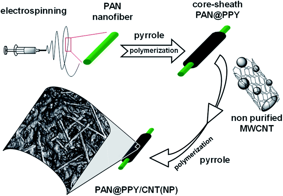 | ||
| Fig. 1 Preparation steps of the composite material PAN@PPY–CNT(NP). | ||
PAN fabric is an ideal membrane support due to its high tensile strength, flexibility, and its resistance to degradation at high temperatures and in the acidic conditions needed for the polymerization of the pyrrole sheath.32 Highly oxidized (doped) PPY used for the sheath is known as an electrical conductor and an efficient hole shuttle33,34 in a wide pH range, given its low response to acid/base dedoping with pH change.35 Among other commonly used conducting polymers, PPY is the best compromise between the cost of production and stability in the working conditions, i.e. UV-Vis irradiation and temperature ≤ 50 °C.32
The interaction between PPY and CNT(NP) on the surface is expected to generate a synergistic effect36,37 in the removal efficiency as the PPY sheath offers an additional surface area for the adsorption of substrates and delocalizes/collects the reactive charge carriers photogenerated in the nanotube. On the other hand, the high surface area and conductivity of CNTs have been reported to increase the redox properties of PPY.36
Experimental
Chemicals and materials
PAN (MW 50![[thin space (1/6-em)]](https://www.rsc.org/images/entities/char_2009.gif) 000–70000 Da, 99%) was purchased from Sarchem Laboratories Inc., New Jersey. Pyrrole (98%), ammonium peroxydisulfate (APS), 4-dodecylbenzene sulfonic acid (DBSA) 99%, HCl 12 M, Rhodamine B (RB), Methyl Orange (MO), and naphthalene were purchased from Sigma Aldrich, 5,5-dimethyl-1-pyrroline-N-oxide (DMPO) from Enzo Life Sciences Inc., New York. Dimethylformamide (DMF) was supplied by Fisher Scientific, H3PO4 (85%) by Carlo Erba, CH3CN (Chromasolv for HPLC, purity ≥ 99.9%) by Honeywell. All the chemicals were used without further purification. Water was purified with a Milli-Q plus apparatus (TOC = 2 ppb, conductivity 18.2 MΩ cm). The commercial multiwalled carbon nanotubes employed were Nanocyl™ NC7000 industrial grade, purchased from Nanocyl S.A., Belgium. Their reported features were: 18 outer mean diameter 9.5 nm, average length 1.5 μm, specific surface area 475 m2 g−1, amorphous carbon pyrolytically deposited on the outer layer, C purity 90%, and metal oxides content 10% (1% transition metals). Reported impurities, determined by inductively coupled plasma mass spectrometry (ICP-MS), were: Al (5.9 wt%), Fe (0.5 wt%), and Co (0.2 wt%). This material was used without any further purification and is referred to in this article as CNT(NP), where NP stands for NanoParticles or Non-Purified.
000–70000 Da, 99%) was purchased from Sarchem Laboratories Inc., New Jersey. Pyrrole (98%), ammonium peroxydisulfate (APS), 4-dodecylbenzene sulfonic acid (DBSA) 99%, HCl 12 M, Rhodamine B (RB), Methyl Orange (MO), and naphthalene were purchased from Sigma Aldrich, 5,5-dimethyl-1-pyrroline-N-oxide (DMPO) from Enzo Life Sciences Inc., New York. Dimethylformamide (DMF) was supplied by Fisher Scientific, H3PO4 (85%) by Carlo Erba, CH3CN (Chromasolv for HPLC, purity ≥ 99.9%) by Honeywell. All the chemicals were used without further purification. Water was purified with a Milli-Q plus apparatus (TOC = 2 ppb, conductivity 18.2 MΩ cm). The commercial multiwalled carbon nanotubes employed were Nanocyl™ NC7000 industrial grade, purchased from Nanocyl S.A., Belgium. Their reported features were: 18 outer mean diameter 9.5 nm, average length 1.5 μm, specific surface area 475 m2 g−1, amorphous carbon pyrolytically deposited on the outer layer, C purity 90%, and metal oxides content 10% (1% transition metals). Reported impurities, determined by inductively coupled plasma mass spectrometry (ICP-MS), were: Al (5.9 wt%), Fe (0.5 wt%), and Co (0.2 wt%). This material was used without any further purification and is referred to in this article as CNT(NP), where NP stands for NanoParticles or Non-Purified.
Synthetic steps
After APS addition, the solution was kept at 4 °C for 90 min, until it became dark green. Then, it was added drop by drop on the PAN mats, which were lying horizontally on a hydrophobic support. The mats were impregnated with an average of 0.12 ml cm−2 and allowed to dry naturally. The impregnation step was repeated 3 times, after 4 and 7 hours, keeping fixed the temperature at 4 °C during the whole process. In the end, dark green mats were obtained. These PAN nanofibers covered with a homogeneous PPY conducting sheath will be later referred to as PAN@PPY mat.
Synthesis of control materials
The contribution of the different components to the combined material PAN@PPY–CNT(NP), in terms of mechanical resistance and removal efficiency, was evaluated with materials produced by skipping at least one of the preparation steps, as described in Table 1.| Name | Preparation | Description and scope |
|---|---|---|
| PAN@PPY–CNT(NP) | PAN@PPY mat, covered with the CNT(NP) suspension and finally with the pyrrole polymerizing solution | Complete system |
| PAN@PPY | PAN nanofibers just coated with PPY | Reference material to indirectly investigate the CNT(NP) contribution to the removal efficiency of the complete system |
| PAN–CNTcold | PAN mat just covered with the CNT(NP) suspension and then dried at 4 °C for 2 cycles (without PPY) | Reference material to indirectly investigate the PPY photoactivity and the role of PPY as entrapping/binding agent for the CNT(NP)s |
| PAN–CNT(NP) | PAN mat just covered with the CNT(NP) suspension and then dried at 100 °C for 1 h, for 2 cycles | Same as PAN–CNTcold, but with a higher drying temperature to promote the attachment of CNT(NP)s on PAN |
| PAN@PPY–(CNT) | PAN@PPY mat, covered with the CNT(NP) suspension for 2 cycles. No final coverage with PPY was applied | Reference material to investigate the effect of the final PPY layer on the mechanical stability of the CNT(NP) layer |
| PAN@CNT-PPY | PAN mat first covered with the CNT(NP) suspension, for 2 cycles, then with the pyrrole polymerizing solution (no initial coverage with PPY) | Reference material to indirectly investigate the role of the initial PPY functionalization of the PAN surface for the subsequent CNT(NP) layer attachment |
| PAN@PPY–CNT | Same as PAN@PPY–CNT(NP), but with HCl-purified CNTs | Reference material to indirectly investigate the photocatalytic effect of the metal oxide NPs in the CNT(NP)s |
Material characterization
High-resolution transmission electron microscopy (HRTEM) was carried out on a JEOL JEM 3010UHR (300 kV) TEM fitted with a single crystal LaB6 filament. The CNT(NP) sample was prepared from a 10 ppm aqueous suspension dry-deposited on Cu “holey” carbon grids (200 mesh). Fourier-transform infrared (FT-IR) spectra were obtained with a Bruker IFS28 spectrophotometer equipped with a Globar source and a DTGS detector, working at 128 scans with 4 cm−1 resolution in the 4000–400 cm−1 range. The sample was prepared by pressing a ground mixture of 1% CNT(NP)s with 99% dry KBr. Scanning Electron Microscopy (SEM) was carried out with a FEI Inspect F50 field emission SEM microscope. The samples were coated with a 4 nm Pt layer (LEICA EM ACE600 sputtering machine).The surface composition of the materials was characterized by X-ray Photoelectron Spectroscopy (XPS) on a Thermo Scientific Kα spectrometer, using Al Kα radiation (1486 eV) and an X-ray spot size of 400 μm. To prevent surface charging during the measurement, the samples were hit with a flood gun shooting low-energy electrons (14 eV). Survey scans were acquired with a pass energy of 200 eV and 1.0 eV resolution; these parameters changed to 50 eV and 0.1 eV, respectively, for high-resolution scans. The curve fitting analysis was performed through Avantage Software (ver. 4.60) using Gaussian–Voigt curve functions, the background was subtracted by the Smart method. The reported XPS results are the average of data collected on 3 different spots on 2 samples for each material.
Electron Paramagnetic Resonance (EPR) was employed to study the photogeneration of reactive ˙OH using DMPO as a trapping agent. EPR spectra were recorded at room temperature with a Bruker ESR 300E X-band spectrometer. The acquisition parameters were as follows: frequency 9.78 GHz, microwave power 5 mW, center field 3470 G, sweep width 80 G, receiver gain 1 × 10⁵, modulation amplitude 0.41 G, conversion time 40.96 ms. The materials were immersed in 5 ml of pure water and irradiated for 60 min in the same conditions chosen for the removal efficiency measurements (see below). Then, 10 μl of spin trap were added, keeping the mat under illumination for an additional 10 min. After irradiation, an aliquot of the solution was withdrawn in a capillary quartz tube and the EPR spectrum was immediately acquired.24,38
In order to investigate the stability of the various functionalized fibers, the amount of carbon released in 10 ml of water from 2 cm2 of the mat was measured using a total organic carbon analyzer (Shimadzu TOC model 5000). Before TOC analysis, the mats were exposed to the same irradiation conditions chosen for the removal efficiency measurements, for different increments of time (0 min to 120 min).
The tensile properties of the PAN@PPY–CNT(NP) composite were determined through a uniaxial tensile test, performed on a computer-controlled mechanical testing machine (Ernest F. Fullam, Inc.) equipped with a 25 lb load cell. The samples were loaded at a rate of 0.01 mm s−1 until failure. The specimens were prepared by cutting the fibrous mats into rectangles with 30 mm × 8 mm size.
The tensile strain was calculated as the change in length divided by the initial length of the sample (i.e. 30 mm), the maximum elongation (elongation at break) was measured at the point of sample failure. The tensile stress was calculated as the recorded load divided by the sample cross-sectional area. To calculate the cross section, the mat thickness was measured by a screw micrometer. The ultimate tensile strength was measured as the stress at the point of the first sample failure. Young's modulus corresponded to the slope of the initial, linear portion of the stress–strain curve. The reported values are averages calculated from tensile stress–strain curves for n = 3 samples for each mat.
Removal efficiency of model contaminants
The substrates tested were RB (10−5 M), MO (10−5 M), naphthalene (5 ppm). The substrate evolution measurements were carried out on 5 ml aqueous solutions containing the target molecule and one of the various functionalized mats (2 cm2, 6 mg), contained in plugged cylindrical Pyrex cells (4.0 cm diameter and 2.5 cm height, cut-off at 295 nm). The tests were carried out under irradiation using a sunlight simulator device (SolarBox, CO.FO.ME.GRA, Milan), equipped with a 550 W xenon lamp (integrated irradiance in the cell: 30 ± 1 W m−2 in the 340–400 nm range, 128 ± 6 W m−2 in the 400–520 nm range). The lamp emission spectrum (reported in Fig. S1†) and incident photon flux were recorded with a calibrated spectrum radiometer (Ocean Optics SD2000 CCD spectrophotometer) equipped with optic fiber and a CC-3-UV-T cosine corrector. Before irradiation, the suspensions were left in the dark for 2 hours, to achieve the adsorption–desorption equilibrium between the substrates and the materials. A small volume of solution was withdrawn regularly, from 0 min to 120 min, to determine the evolution profile of the adsorption isotherm. During irradiation, the solutions were not stirred. After irradiation, the solutions were filtered through a 0.45 μm hydrophilic PTFE membrane (Millipore Millex-LCR) and analyzed. The RB and MO adsorption and degradation kinetics were recorded with a Varian CARY 100 UV-Vis spectrophotometer. The naphthalene adsorption and degradation kinetics were monitored by HPLC-UV (YL9300 HPLC System) equipped with a Lichrospher R100 RP-18 (5 μm) column. The injection volume was 50 μl, and the elution was carried out at 1 ml min−1 in isocratic mode with aqueous H3PO4 (4.2 mM):CH3CN 65:35 (retention time: 9.5 min). After completing one removal cycle, the mats were withdrawn from the solution, rinsed with abundant water, and used to perform a subsequent cycle. The removal efficiency was estimated fitting the time evolution of the substrate with a mono-exponential decay law C = C0exp(−kt). The first order constant k obtained was taken as a relative measure of the removal efficiency. C0 corresponded to the concentration of free substrate at the beginning of irradiation, i.e. the concentration detected after adsorption on the catalyst for 2 hours in the dark.
Results and discussion
Characterization of CNT(NP)
The characterization of the CNT(NP)s used in this work is described elsewhere in the literature.18,24 In Fig. 2, the TEM micrographs of the as-received material indicate that it consists of ropes and yarns of entangled nanotubes, agglomerated in larger disordered structures with sizes ranging from microns to millimeters (panel a).18,24 HRTEM pictures in panels (b) and (c) show in detail single disentangled carbon nanotubes and confirm the presence of both an amorphous carbon layer on the nanotube surface (white squares in panel b) and amorphous metal oxide NPs (white circle in panel c). The NPs are residues of the catalyst used for the CNTs synthesis and appear attached both to the surface and within the nanotube structure.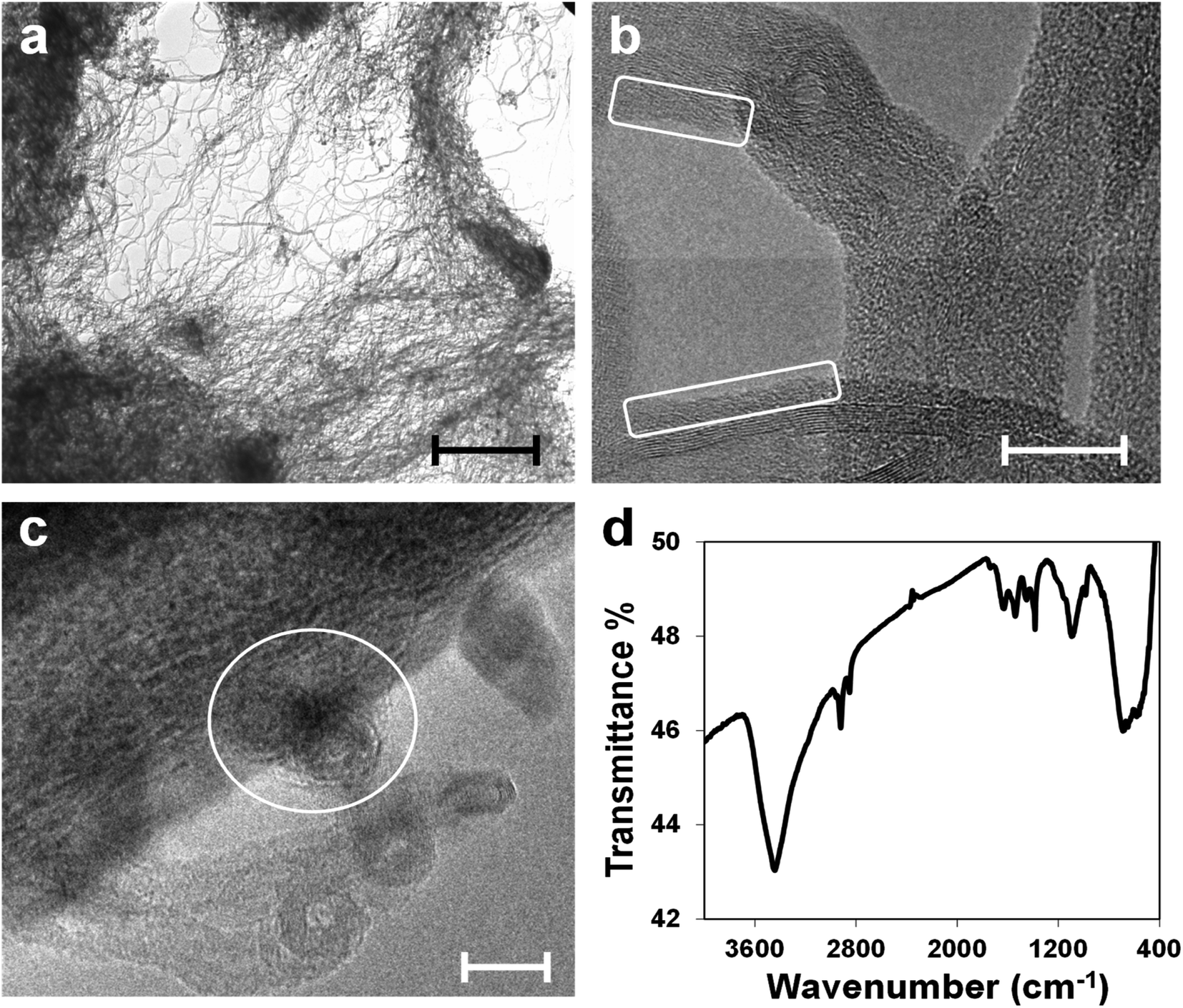 | ||
| Fig. 2 (a) TEM micrograph of pristine CNT(NP)s, scale bar: 1 μm. (b and c) HRTEM micrographs of pristine CNT(NP)s which show the amorphous carbon layer on the CNT(NP) surface (white squares) and metallic NPs embedded in the CNT(NP) structure (white circle), scale bars: 10 nm. (d) FT-IR spectrum of pristine CNT(NP)s. | ||
NP composition has been already determined and roughly quantified through X-ray photoelectron spectroscopy (XPS), energy-dispersive X-ray spectroscopy (EDS), and X-ray diffraction (XRD) on the residues of the thermogravimetric analysis (TGA).24 The NPs located on the surface consist almost entirely of aluminum oxide, used as the catalyst support,12,39 and smaller amounts of iron oxide, cobalt oxide, and silicon oxide. They are removed through treatments with concentrated acids.24
IR spectroscopy performed on the CNT(NP)s (Fig. 2, panel d) reveals the presence of oxidized carbon, generated during the nanotube synthesis, as well as the entrapped metal oxide NPs. The characteristic band at 3440 cm−1 corresponds to the O–H stretching vibration due to nanotube surface groups. The small peak at 1707 cm−1 (C![[double bond, length as m-dash]](https://www.rsc.org/images/entities/char_e001.gif) O stretching), together with the sharp and intense peak at 1385 cm−1 (O–H bending) and the band centered at 1095 cm−1 (C–O stretching), suggest the presence of surface carboxylic groups. The wide band, which ranges from 830 to 460 cm−1 is ascribed to the metal–oxygen vibration modes of aluminum oxide, iron oxide, and cobalt oxide. Al–O absorption displays a characteristic broad band that starts at around 900 cm−1 and dominates the fingerprint region. Bands at 690–670 cm−1 and 580–560 cm−1 may be assigned to Fe–O and Co–O vibrations.40–42
O stretching), together with the sharp and intense peak at 1385 cm−1 (O–H bending) and the band centered at 1095 cm−1 (C–O stretching), suggest the presence of surface carboxylic groups. The wide band, which ranges from 830 to 460 cm−1 is ascribed to the metal–oxygen vibration modes of aluminum oxide, iron oxide, and cobalt oxide. Al–O absorption displays a characteristic broad band that starts at around 900 cm−1 and dominates the fingerprint region. Bands at 690–670 cm−1 and 580–560 cm−1 may be assigned to Fe–O and Co–O vibrations.40–42
Functionalization of PAN nanofibers with PPY and CNT(NP)
PPY forms by chemical oxidative polymerization of pyrrole monomer in the presence of APS, a strong oxidant.43 The oxidative reaction generates a heavy positive doping on the pyrrole rings of the PPY chains. The DBS negative counterions firmly interact with the positive nitrogen centers of the PPY, preserving the excess of positive charge, i.e. maintaining PPY in its doped state.44SEM enables investigation of the microscopic texture and the structural evolution of the PAN@PPY nanofibers, before and after the functionalization with CNT(NP)s. Fig. 3a and S2† show a magnification of the dark grey PAN@PPY mat reported in the inset. The nanofiber surface is rough, due to the PPY sheath. Some bigger PPY domains appear where two or more fibers are in contact. Fig. 3b illustrates how the final thin layer of PPY, described above, effectively encloses the CNT(NP)s on the surface of the PAN@PPY fibers.
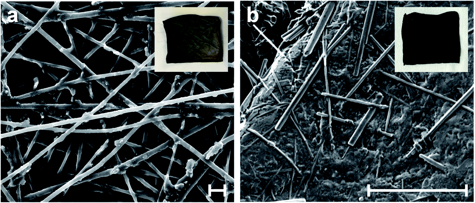 | ||
| Fig. 3 SEM micrographs of (a) PAN@PPY nanofibers, and (b) CNT(NP)s entrapped on PAN@PPY surface (PAN@PPY–CNT(NP) material). Insets report the pictures of the corresponding mats. Scale bars: 5 μm. | ||
We immersed the several control materials described above in water and manually shook them to estimate their mechanical resistance in the photocatalytic conditions. The PAN–CNT(NP) mat exhibits excellent mechanical stability when immersed in water, as it does not swell and CNT(NP)s do not detach from the fibers. PAN–CNTcold is not mechanically stable in water as it suddenly swells and most nanotubes detach from the fibers. This material was not tested further for its removal efficiency towards model contaminants.
PAN@PPY–(CNT) results mechanically stable in water (neither swelling nor folding occurs), but a large part of nanotubes detach from the fibers soon after immersion. Conversely, the PAN@CNT–PPY mat quickly swells in contact with water. Both these control materials were not chosen for subsequent tests due to their low mechanical features. Overall, these results prove that both the first and the final PPY layers are necessary to ensure the desired stability and mechanical properties.
We investigated the chemical composition of the mat surface through XPS. XPS is a suitable technique for non-microporous carbons like CNTs and nanofibers; currently, it is the most required technique to evaluate carbon surface chemistry.45 The wide-scan spectra are shown in Fig. S3† and the mean elemental distribution of the surveys are summarized in Table 2. As expected, the PAN@PPY nanofibers are mostly composed of C and N. The remarkable abundance of O and the small amount of S arise from the sulfonic group of the DBS anions, which are preferentially located on the surface and shield the N of the PPY rings almost stoichiometrically. Adsorption on PPY must be affected by the bulky negative heads and the long (dodecyl) apolar tails of DBS. Positively charged and/or hydrophobic substrates are expected to be favored over negatively charged ones.
| Sample | Atomic% | |||
|---|---|---|---|---|
| C 1s | N 1s | O 1s | S 2p | |
| PAN@PPY | 72 ± 4 | 10 ± 1 | 14 ± 3 | 4 ± 1 |
| PAN@PPY–CNT(NP) | 76 ± 4 | 8 ± 1 | 13 ± 2 | 3 ± 1 |
| PAN@PPY–CNT(NP) (richer in CNTs) | 90 ± 3 | 3 ± 1 | 6 ± 2 | 1 ± 0.5 |
Fig. S4† shows the high-resolution C 1s, N 1s, O 1s, and S 2p spectra, together with the components obtained from curve fitting, their binding energy, chemical assignments, and their discussion. The PPY surface appears composed at most of aromatic sp2 C and N moieties. The heavy oxidation has generated a high density of bipolarons, localized on the N atoms (i.e. N+, in 1/3 of the pyrrole rings). Superficial C–OH and CO are negligible in the prepared PPY. All the values measured are in close agreement with XPS analysis on PPY prepared via oxidative polymerization with APS.46
The surface of the PAN@PPY–CNT(NP) composite is richer in carbon, which spans from 75 to 90% depending on the local amount of entrapped nanotubes. Areas poorer in CNTs show the same elemental composition of PAN@PPY, because of the superficial thin PPY layer deposited during the last step of the PAN@PPY–CNT(NP) preparation. Areas richer in CNTs show an absolute predominance of carbon and small amounts of N, S, and O. Oxygen is detected in higher amounts; according to its high-resolution spectrum, it is present predominantly in the form of hydroxyl groups (see Fig. S4 and related discussion in the ESI†).
Production of ˙OH under irradiation
Photogenerated ˙OH radicals were detected by EPR using DMPO as a radical trap. The mats were tested after each preparation step, including PAN@PPY supporting CNTs after acid washing. The EPR spectra of pristine CNT(NP)s and CNT(NP)s after their treatment in concentrated HCl were taken as control experiments (Fig. S5†). Fig. 4 reveals that the coverage of PAN@PPY with CNT(NP)s leads to an increase of photoproduced ˙OH radicals. On the other hand, CNTs treated with HCl do not generate ˙OH. The mats functionalized with CNTHCl show a negligible photoproduction of ˙OH even compared to that of PAN@PPY. This evidence proves the central role of the Co, Fe and Al NPs24 in the photocatalytic activity of the CNT(NP)s studied, which disappears when the HCl treatment removes the metal traces from the exposed surfaces of the nanotube.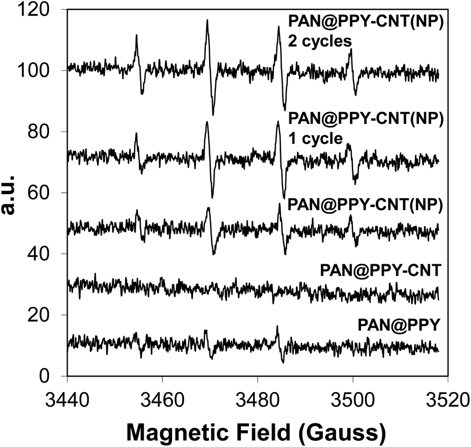 | ||
| Fig. 4 EPR spectra of PAN@PPY, PAN@PPY–CNTHCl, and PAN@PPY–CNT(NP) mats. PAN@PPY–CNT(NP) are tested right after the synthesis, after the 1st cycle of experiments on RB removal, and after the 2nd cycle. | ||
EPR measurements in Fig. 4 also demonstrate that the ˙OH photogeneration by the PAN@PPY–CNT(NP) mat does not decrease after repeated photodegradation cycles, in contrast to what is usually reported for many photocatalysts. Surprisingly, it slightly increases after the first cycle. This behavior is in agreement with the increased H2O2 photoproduction observed in the presence of CNT(NP)s which have previously been exposed to UVA light.24
UV-Vis irradiation seems to improve the photocatalytic properties of CNT(NP)s, possibly by inducing a reduction of the oxygen-containing groups on the nanotube surface,24 without deactivating or removing the residual metal oxide NPs.
Measurements of removal efficiency
The removal efficiencies of PAN–CNT(NP), PAN@PPY, and PAN@PPY–CNT(NP) were tested towards different target molecules such as RB, MO, and naphthalene. All the experiments have been carried out in static conditions, i.e. without stirring. Each material underwent preliminary adsorption tests in the dark. In all cases, the substrates and the mats reached the adsorption–desorption equilibrium within one hour (Fig. S6†).MO does not adsorb on the functionalized fibers, so its photodegradation is negligible. Since MO is an anionic derivative of the benzenesulfonic acid, some Coulomb repulsion most likely establishes between MO and the mat. Conversely, the uncharged naphthalene and RB, a neutral species above pH 4, partially adsorb on the PAN@PPY and PAN@PPY–CNT(NP) fibers and are then photodegraded. This indicates that the mat is most probably negatively charged at the pH of the test (around neutrality, as no pH adjustment was done). The pHpzc of hybrid materials can change considerably with their composition due to the local (charge) equilibration at their interfaces. This effect is expected to be larger with materials with large electron mobility, such as the composites reported here.47
As shown in Fig. S6,† the adsorption capacity of PAN@PPY–CNT(NP) mats is 40 ± 10% in the case of RB and 35 ± 10% in the case of naphthalene, in each removal cycle. The adsorption capacity of the PAN@PPY mats is close to the one of PAN@PPY–CNT(NP), specifically 5–10% lower for both substrates. This demonstrates a major role of the PPY layer in the substrate adsorption on PAN@PPY–CNT(NP). According to the literature, the chemical polymerization of PPY in the presence of CNTs induces the formation of aggregates that deposit on the embedded nanotubes,36 altering their adsorption properties. The adsorption capacity of CNT(NP)s in PAN@PPY–CNT(NP) is reasonably low because they are mostly immersed in the PPY matrix, as clearly displayed in Fig. 3b. The CNT(NP) adsorption ability appears greatly reduced also in the PAN–CNT(NP) mat, in consequence of the interactions between the active sites of CNT(NP)s with the surface groups of the PAN support, promoted by the thermal treatment performed during the PAN–CNT(NP) preparation.
Fig. 5 shows the removal efficiency of the different mats tested for RB, together with the substrate direct photolysis. The direct photolysis contribution, caused by the dye absorption in the emission range of the excitation lamp, is not negligible in the case of RB. This effect is responsible for no more than 20% of the RB abatement. PAN–CNT(NP) exhibits a low removal efficiency toward both RB and naphthalene (see also Fig. S7†), close to the direct photolysis contribution. This result is quite unexpected given the high amount of photogenerated ˙OH detected by EPR (Fig. S5a†).
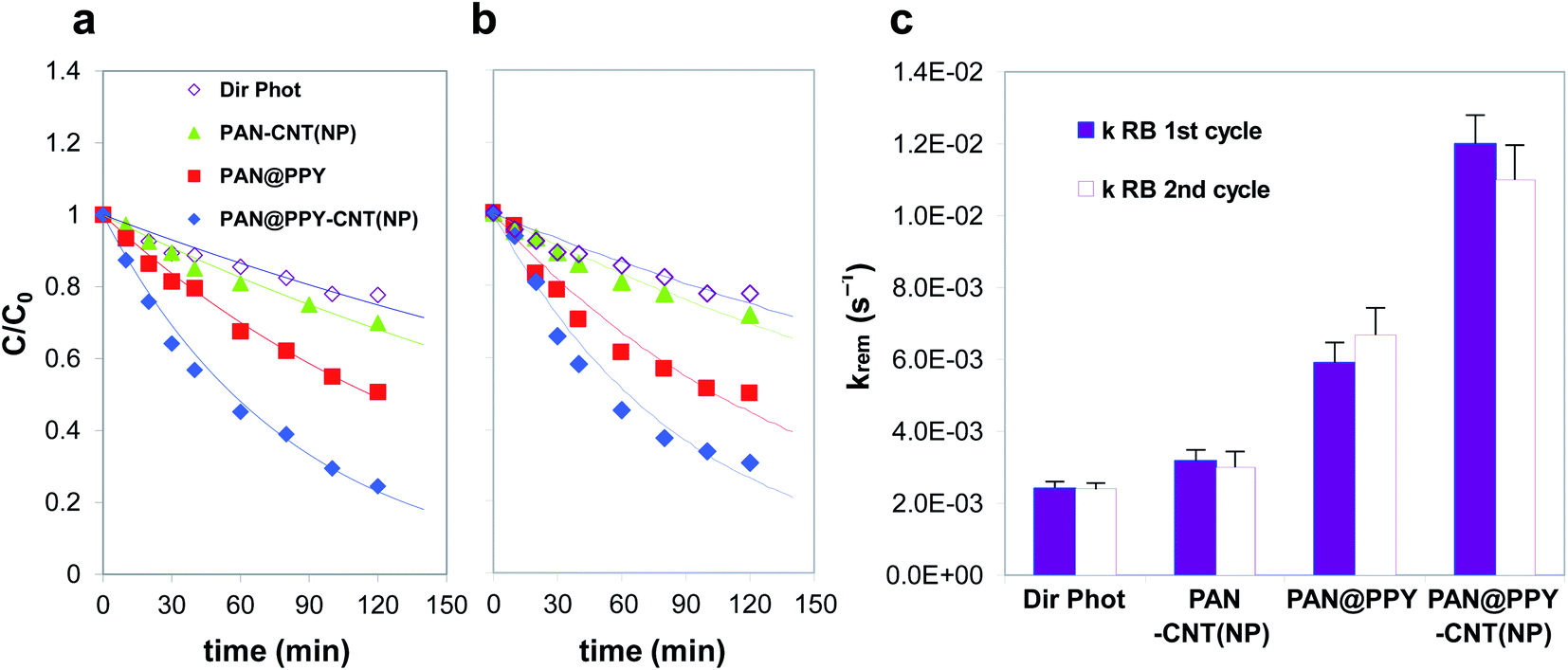 | ||
| Fig. 5 (a) First and (b) second removal cycles of RB (10−5 M) in the presence of PAN–CNT(NP) (▲), PAN@PPY (■), and PAN@PPY–CNT(NP) (◆) mats under Solarbox irradiation. The direct photolysis of the target substrate (◇) is also reported. (c) First-order kinetic constants calculated from the time evolution of the substrate concentration shown in panels (a) and (b). | ||
PAN@PPY removes both RB and naphthalene (see also Fig. S7†) even if EPR detects a little photoproduction of ˙OH (Fig. 4). The small bandgap of heavily doped PPY is not able to generate such reactive species. Another mechanism not detected by EPR with DMPO, such as the direct transfer of h+, is most probably responsible for the degradation of the RB and naphthalene molecules adsorbed on the PPY sheath.32–34
It is worth mentioning that the ROS concentration in the proximity of the irradiated system could be some orders of magnitude higher than the value measured via EPR in the bulk aqueous phase, using a trapping substrate.28,48
Since these short-lifetime reactive species are produced and scavenged close to the nanotube surface,49,50 they influence the CNT(NP) and PPY–CNT(NP) surface chemistry much more than what is expected from their bulk concentrations. When the substrate does not adsorb on the mat (e.g. MO), the reactive species generated on the CNT(NP) during irradiation are preferentially scavenged by the nanotube itself or by the polymeric support (PAN or PPY).49,50 As the CNT(NP)s are in close contact with the fibers, the reaction with the support is extremely favoured compared to that with the dissolved substrates. Conversely, when the target molecule is adsorbed it can effectively compete for the reaction with the photoinduced reactive species.
The comparison of the photodegradation kinetic constants for naphthalene (Fig. S7†) reveals that the presence of CNT(NP)s onto the PAN@PPY nanofibers does not improve their performance. As already mentioned above and previously demonstrated by our group,32 this indicates that the naphthalene removal is mostly determined by a mechanism involving another reactive species at the PPY interface, i.e. h+. On the contrary, CNT(NP)s enhance the RB photodegradation, as the PAN@PPY–CNT(NP) removal efficiency is higher than the sum of the two individual components PAN@PPY and PAN–CNT(NP).
In agreement with EPR results, the PAN@PPY–CNT mat does not show any superior photodegradation ability towards RB, compared to bare PAN@PPY. This evidence again confirms that the metal oxide NPs are responsible for the photo-redox properties of the CNT(NP)s used, as also shown in our previous report.24
The photocatalytic efficiency of PAN@PPY–CNT(NP) for the RB abatement is comparable or superior to other similar materials reported in the literature, based on photoactive composites that involve carbon nanotubes or carbon-metal photocatalytic hybrids supported on polymeric membranes.51,52 However, these performances are lower if compared with composites based on benchmark photocatalytic materials, such as TiO2.53 Though, the significant advantage of our material toward these is its recycling for subsequent photodegradation cycles without the need of (not scalable) nanofiltration steps in between.
The photodegradation efficiency of each sample during the second removal cycle (Fig. S7b†) is close to the one measured during the first cycle, proving their stability in the operating conditions. As an exception, naphthalene's photodegradation in the presence of both the PAN@PPY and PAN@PPY–CNT(NP) mats reaches a plateau during the first removal cycle (see Fig. S7†). Washing the fibers restores their photocatalytic activity that, however, appears lower than in the first cycle. These results imply that PAN@PPY and PAN@PPY–CNT(NP) partially oxidize naphthalene instead of mineralizing it completely to CO2 and H2O. Some of the naphthalene degradation products remain adsorbed on the mats and progressively saturate all the catalytic sites on PPY. The washing step removes a great part of these compounds except for the ones irreversibly adsorbed on the most active PPY sites. This explains both the loss of removal efficiency between the first and subsequent cycles, and the constant removal efficiency measured during the subsequent cycles.
According to previous reports,24,49 UVA irradiation of a CNT(NP) aqueous suspension generates e−–h+ excitons in the nanotubes, which evolve in separated-charge transient states. These transient states mostly consist of holes, localized on the metal oxide NPs, and CNT radical anions. Charge recombination is the main competitive decay process in CNTs washed with concentrated HCl. The reaction of CNT radical anions with oxygen yields O2˙− and then H2O2.24 The holes on the NPs are scavenged by amorphous carbon on the nanotube surface or by the substrates adsorbed on the nanotube.10,20,24,28
In our combined system, the entrapped CNT(NP)s seem to act mostly as a source of charge carriers, while the adsorption of target substrates occurs preferentially onto the PPY sheath as many of the free sites on the nanotube are engaged in interactions with PPY.36,37 Under visible light, the PPY chains also convert into a separated-charge excited state which induces a charge separation at the interface with CNT(NP)s.37 The p-conjugated structure of PPY acts as an efficient electron donor (fast injection of the photoexcited e− from PPY into the nanotube), as well as an efficient shuttle of the holes photogenerated in the NPs of the interfaced nanotube.33,34 The reactive holes from the oxide NPs are then collected and delocalized on PPY where they directly oxidize the adsorbed substrates or form ˙OH radicals. The PPY sheath may also partially act as a charge scavenger, with consequent dedoping or partial degradation of the PPY chains.
In addition to the mechanical support, the photoactive PPY mat plays a major role in increasing the removal efficiency of the combined system, as the heterojunction formed at the PPY–CNT(NP) interface inhibits the recombination of the electrons and holes generated under irradiation.32
Stability under irradiation
The amount of organic carbon released by the mats under UV-Vis irradiation is used to further evaluate fiber stability. TOC analysis reveals that the mats release carbon species just within the first 15–30 min (see Table S1†). The carbon released from the PAN–CNT(NP) mats is close to the limit of detection (the TOC values are analogous to that of Milli-Q water). PAN@PPY mats release 0.21 mg cm−2 of carbon, which is comparable to the value of 0.16 mg cm−2 measured with PAN@PPY–CNT(NP). Considering that, approximately 0.04 mg CNT(NP) are adsorbed per cm2 mat (see Experimental section) and that any release by CNT(NP) after irradiation is expected to be negligible as no C release is observed for PAN–CNT(NP) with the irradiation time (see Table S1†), it is suggested that the organic carbon released by the mat is due to the PPY coating. These observations are in line with the observed stability of the EPR signals and the photocatalytic efficiency over multiple irradiation cycles, strongly supporting that CNT(NP) and the amorphous carbon released during irradiation remain attached to the mat. Otherwise, a decrease of the catalytic efficiency would have been observed.The nanotubes in the PAN–CNT(NP) mats result partially covered with a layer of PPY which, as discussed above, improves remarkably their stabilization on the mat. This PPY layer also helps to prevent the release of amorphous carbon and metallic particles, the photoactive components of CNT(NP). This is confirmed by the stability of the EPR signals and photocatalytic efficiency over multiple irradiation cycles.
Through tensile tests, we also assessed the mechanical properties of the PAN@PPY–CNT(NP) mats before and after 1 week of continuous irradiation in the photocatalytic conditions described above in the section ‘Removal efficiency of model contaminants’ (the equivalent of 84 photodegradation cycles of 2 hours represented in Fig. 5). Typical tensile stress–strain curves are shown in Fig. 6. The responses are almost linear in the early loading stage, then they display a marked plastic behavior, without any sudden fracture. We used the tensile curves to determine the tensile modulus, elongation at break, and tensile strength for the PAN@PPY–CNT(NP) membranes, which are listed in Table S2.†
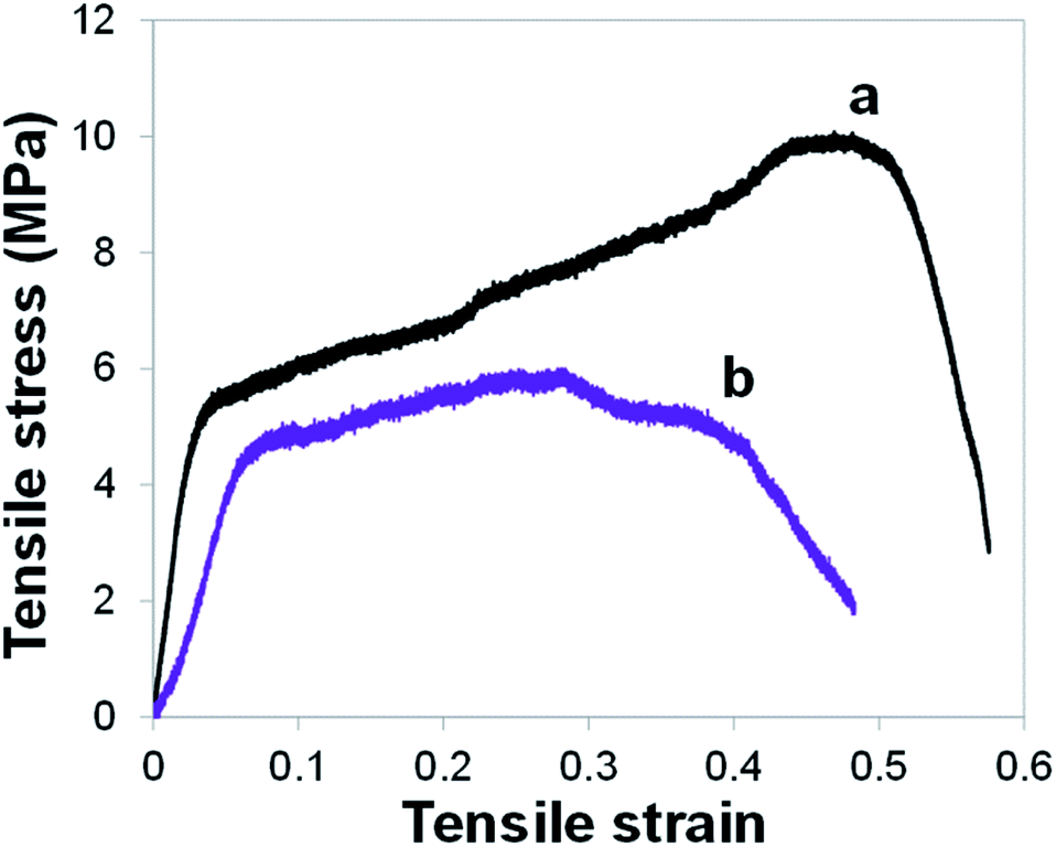 | ||
| Fig. 6 Tensile stress–strain curves for PAN@PPY–CNT(NP) mat before irradiation (a) and after 1 week of continuous irradiation in the conditions chosen for the photocatalytic tests (b). | ||
After 1 week irradiation, the sample ultimate tensile strength as well as their average tensile modulus drop respectively to the 60% and 50% of their original mean values (i.e. ∼10 and ∼200 MPa). Also, the elongation at failure decreases from 50% to 30%, on average. The results indicate that the prolonged photocatalytic activity partially compromises the mechanical properties of the PAN@PPY–CNT(NP) membranes, which however can withstand several more photocatalytic cycles. Therefore, the PAN nanofabric core appears suitable as a mechanical support for photocatalytic applications.
Conclusions
We synthesized a photocatalyst for the abatement of water contaminants under UV-Vis irradiation, based on commercially available CNT(NP)s supported on conducting, core–sheath PAN@PPY nanofibers. Compared to the two separate components PAN@PPY and CNT(NP)s (actually PAN–CNT(NP)), the combined system PAN@PPY–CNT(NP) shows a synergistic increase in the efficiency of RB removal. However, the presence of CNT(NP)s is not beneficial for the removal of naphthalene. All the materials tested retain their catalytic activity during subsequent cycles. We also confirmed that the metal oxide NPs embedded in CNT(NP)s play a key role in their photocatalytic properties and in that of PAN@PPY–CNT(NP), i.e. they are the source of charge carriers and then ˙OH radicals under UV-Vis irradiation. In agreement with the recent research on graphene,54 an impure, less refined carbon-based material like CNT(NP) appears more functional (and inexpensive) to several practical applications than an ideal CNT. The PPY support increases the photodegradation efficiency of PAN@PPY–CNT(NP) thanks to its intrinsic photoactivity and electrical conductivity. The PPY sheath adsorbs most of the substrate, shuttles the reacting holes from the CNT(NP) to the adsorbed substrates, and directly photodegrades the adsorbed substrates through a mechanism that does not involve ˙OH radicals. New supported hybrid materials for photocatalytic applications can be designed based on these features. As an example, CNT(NP)s can be supported on different conducting or semiconducting materials able to enhance even more CNT(NP)'s catalytic activity, i.e. conductive carbon nanofibers. PAN@PPY–CNT(NP) is fabricated through a facile and scalable synthetic procedure, which includes PAN electrospinning and the oxidizing polymerization of PPY. The highly doped PPY sheath forms in water under ambient conditions, as opposed to other conducting polymers, which usually require organic solvents and an inert atmosphere.55 It also exhibits high thermal and mechanical stability under irradiation, with the negligible release of degradation compounds in solution. Finally, the photocatalyst in the form of a flexible mat allows the immediate reuse after washing, avoiding the recovery through any non-scalable filtration of the treated water. All these features make PAN@PPY–CNT(NP) a promising candidate for future photocatalytic applications on a large scale, which include decontamination of water containing emerging persistent pollutants.Conflicts of interest
There are no conflicts of interest to declare.Acknowledgements
We gratefully acknowledge the support from the Marie Curie International Research Staff Exchange Scheme Fellowship (MAT4TREAT, proposal no. 645551) within the Horizon 2020 European Community Framework Programme, as well as local funding of the University of Torino.Notes and references
- M. K. Samani, N. Khosravian, G. C. K. Chen, M. Shakerzadeh, D. Baillargeat and B. K. Tay, Int. J. Therm. Sci., 2012, 62, 40 CrossRef CAS.
- Y. Ando, X. Zhao, H. Shimoyama, G. Sakai and K. Kaneto, Int. J. Inorg. Mater., 1999, 1, 77 CrossRef CAS.
- K. S. Ibrahim, Carbon Lett., 2013, 14, 131 CrossRef.
- L. F. Shen, C. Z. Yuan, H. J. Luo, X. G. Zhang, K. Xu and F. Zhang, J. Mater. Chem., 2011, 21, 761 RSC.
- Y. Cao, S. Cong, X. Cao, F. Q. Wu, Q. Z. Liu, M. R. Amer and C. W. Zhou, Top. Curr. Chem., 2017, 375, 75 CrossRef PubMed.
- J. N. Coleman, U. Khan, W. J. Blau and Y. K. Gun'ko, Carbon, 2006, 44, 1624 CrossRef CAS.
- I. O'Connor, S. De, J. N. Coleman and Y. K. Gun'ko, Carbon, 2009, 47, 1983 CrossRef.
- D. Movia, E. Del Canto and S. Giordani, J. Phys. Chem. C, 2010, 114, 18407 CrossRef CAS.
- C. H. See and A. T. Harris, Ind. Eng. Chem. Res., 2007, 46, 997 CrossRef CAS.
- D. Bom, R. Andrews, D. Jacques, J. Anthony, B. L. Chen, M. S. Meier and J. P. Selegue, Nano Lett., 2002, 2, 615 CrossRef CAS.
- M. Kumar and Y. Ando, J. Nanosci. Nanotechnol., 2010, 10, 3739 CrossRef CAS PubMed.
- A. Magrez, J. W. Seo, R. Smajda, M. Mionić and L. Forró, Materials, 2010, 3, 4871 CrossRef CAS PubMed.
- J. Prasek, J. Drbohlavova, J. Chomoucka, J. Hubalek, O. Jasek, V. Adam and R. Kizek, J. Mater. Chem., 2011, 21, 15872 RSC.
- R. Andrews, D. Jacques, A. M. Rao, F. Derbyshire, D. Qian, X. Fan, E. C. Dickey and J. Chen, Chem. Phys. Lett., 1999, 303, 467 CrossRef CAS.
- A. Yasuda, N. Kawase, F. Banhart, W. Mizutani, T. Shimizu and H. Tokumoto, J. Phys. Chem. B, 2002, 106, 1849 CrossRef CAS.
- G. Atthipalli, H. Wang and J. L. Gray, Appl. Surf. Sci., 2013, 273, 515 CrossRef CAS.
- S. B. Sinnott and R. Andrews, Crit. Rev. Solid State Sci., 2001, 26, 145 CrossRef CAS.
- C. M. White, R. Banks, I. Hamerton and J. F. Watts, Prog. Org. Coat., 2016, 90, 44 CrossRef CAS.
- Y. Feng, H. Zhang, Y. Hou, T. P. McNicholas, D. Yuan, S. Yang, L. Ding, W. Feng and J. Liu, ACS Nano, 2008, 2, 1634 CrossRef CAS PubMed.
- W. Li, Y. Bai, Y. Zhang, M. Sun, R. Cheng, X. Xu, Y. Chen and Y. Mo, Synth. Met., 2005, 155, 509 CrossRef CAS.
- C. Y. Chen and C. T. Jafvert, Carbon, 2011, 49, 5099 CrossRef CAS.
- Y. S. Hwang, X. Qu and Q. Li, Carbon, 2013, 55, 81 CrossRef CAS.
- A. Joshi, S. Punyani, S. S. Bale, H. Yang, T. Borca-Tasciuc and R. S. Kane, Nat. Nanotechnol., 2007, 3, 41 CrossRef PubMed.
- D. R. Sartori, M. L. Dell'Arciprete, G. Magnacca, P. Calza, E. Laurenti and M. C. Gonzalez, Carbon, 2018, 138, 161 CrossRef.
- B. Sljukic, C. E. Banks and R. G. Compton, Nano Lett., 2006, 6, 1556 CrossRef CAS PubMed.
- G. V. Buxton, C. L. Greenstock, W. P. Helman and A. B. Ross, J. Phys. Chem. Ref. Data, 1988, 17, 513 CrossRef CAS.
- N. T. Alvarez, C. Kittrell, H. K. Schmidt, R. H. Hauge, P. S. Engel and J. M. Tour, J. Am. Chem. Soc., 2008, 130, 14227 CrossRef CAS PubMed.
- X. L. Qu, P. J. J. Alvarez and Q. L. Li, Environ. Sci. Technol., 2013, 47, 14080 CrossRef CAS PubMed.
- M. Minella, D. Fabbri, P. Calza and C. Minero, Curr. Opin. Green Sustain. Chem., 2017, 6, 11 CrossRef.
- M. Sarro, N. P. Gule, E. Laurenti, R. Gamberini, M. C. Paganini, P. E. Mallon and P. Calza, Chem. Eng. J., 2018, 334, 2530 CrossRef CAS.
- S. Tul Muntha, A. Kausar and M. Siddiq, Polym.-Plast. Technol. Eng., 2016, 56, 841 CrossRef.
- G. Capilli, P. Calza, C. Minero and M. Cerruti, J. Mater. Chem. A, 2019, 7, 26429 RSC.
- F. A. Harraz, A. A. Ismail, S. A. Al-Sayari and A. Al-Hajry, J. Photochem. Photobiol., A, 2015, 299, 18 CrossRef CAS.
- Z. Zhang, W. Wang and E. Gao, J. Mater. Sci., 2014, 49, 7325 CrossRef CAS.
- Y. Q. Shen and M. X. Wan, Synth. Met., 1998, 96, 127 CrossRef CAS.
- M. Hughes, G. Z. Chen, M. S. P. Shaffer, D. J. Fray and A. H. Windle, Chem. Mater., 2002, 14, 1610 CrossRef CAS.
- C. F. Zhou, S. Kumar, C. D. Doyle and J. M. Tour, Chem. Mater., 2005, 17, 1997 CrossRef CAS.
- I. Roppolo, A. Chiappone, S. Porro, M. Castellino and E. Laurenti, New J. Chem., 2015, 39, 2966 RSC.
- A. Dupuis, Prog. Mater. Sci., 2005, 50, 929 CrossRef CAS.
- K. Nakamoto, Infrared and Raman spectra of inorganic and coordination compounds, John Wiley & Sons, Hoboken, 2009 Search PubMed.
- A. May-Pat, F. Aviles, P. Toro, M. Yazdani-Pedram and J. V. Cauich-Rodriguez, eXPRESS Polym. Lett., 2012, 6, 96 CrossRef CAS.
- D. Devadatha and R. Raveendran, J. Mater. Sci. Eng., 2013, 3(S11) Search PubMed.
- K. C. Khulbe, R. S. Mann and C. P. Khulbe, J. Polym. Sci., Part A: Polym. Chem., 1982, 20, 1089 CAS.
- Y. Q. Shen and M. X. Wan, Synth. Met., 1998, 96, 127 CrossRef CAS.
- C. O. Ania, P. A. Armstrong, T. J. Bandosz, F. Beguin, A. P. Carvalho, A. Celzard, E. Frackowiak, M. A. Gilarranz, K. László, J. Matos and M. F. R. Pereira, Carbon, 2020, 164, 69 CrossRef CAS.
- J. Tabačiarová, M. Mičušík, P. Fedorko and M. Omastová, Polym. Degrad. Stab., 2015, 120, 392 CrossRef.
- J. Kaur and R. Kant, J. Phys. Chem. C, 2017, 121, 13059 CrossRef CAS.
- D. E. Latch and K. McNeill, Science, 2006, 311, 1743 CrossRef CAS PubMed.
- D. M. Guldi, M. Marcaccio, D. Paolucci, F. Paolucci, N. Tagmatarchis, D. Tasis, E. Vazquez and M. Prato, Angew. Chem., Int. Ed., 2003, 42, 4206 CrossRef CAS PubMed.
- M. Alvaro, P. Atienzar, J. L. Bourdelande and H. Garcia, Chem. Phys. Lett., 2004, 384, 119 CrossRef CAS.
- Y. Yan, H. Sun, P. Yao, S.-Z. Kang and J. Mu, Appl. Surf. Sci., 2011, 257, 3620 CrossRef CAS.
- M. M. Mahlambi, O. T. Mahlangu, G. D. Vilakati and B. B. Mamba, Ind. Eng. Chem. Res., 2014, 53, 5709 CrossRef CAS.
- Y. Huang, D. Chen, X. Hu, Y. Qian and D. Li, Nanomaterials, 2018, 8, 431 CrossRef PubMed.
- L. Wang, Z. Sofer and M. Pumera, ACS Nano, 2020, 14, 21 CrossRef CAS PubMed.
- N. Toshima and S. Hara, Prog. Polym. Sci., 1995, 20, 155 CrossRef CAS.
Footnotes |
| † Electronic supplementary information (ESI) available. See DOI: 10.1039/d0ra10930d |
| ‡ Present address: Department of Materials Engineering, McGill University, Montreal, QC H3A 0C5, Canada. |
| This journal is © The Royal Society of Chemistry 2021 |