
 Open Access Article
 This Open Access Article is licensed under a Creative Commons Attribution-Non Commercial 3.0 Unported Licence
In situ exfoliation and modification of graphite foil in supercapacitor devices: a facile strategy to fabricate high-performance supercapacitors†
Byungkwon Jang ,
Han Kim,
Si-Woo Park,
Minseob Lim,
Jimin Lee,
Gwang-Myeong Go and
Yong-Ho Choa*
,
Han Kim,
Si-Woo Park,
Minseob Lim,
Jimin Lee,
Gwang-Myeong Go and
Yong-Ho Choa*
Department of Materials Science and Chemical Engineering, Hanyang University, Ansan 15588, South Korea. E-mail: choa15@hanyang.ac.kr
First published on 20th January 2021
Abstract
Graphite foils (GFs) are emerging as a new class of electrodes in supercapacitors (SCs) based on their light weight, and high electrical conductivity, although the surface area remains low. A novel method of, in situ electrochemical exfoliation and modification of GF in the assembled SCs, showed high energy density and power density of the SC devices.
Since electric energy is easily converted into other types of energy, considerable efforts have been devoted to developing electric energy storage devices.1 Such devices have been used not only in most electronics but also in transportation, power tools, medical devices, communication, and power supplies.2–5 Among them, supercapacitors as a candidate for high-performance energy storage devices have drawn attention due to their high power density, ultrafast charging, and discharging capability, as well as excellent electrochemical stability.4–6
Carbon-based materials such as activated carbon, have been widely studied for supercapacitors.7–9 However, they cannot be used in a free-standing form and are commonly mixed with a binder and coated onto a metal-based current collector, increasing the weight and volume of supercapacitor devices.7,8 Freestanding carbon structures without current collectors, such as graphite foils, are emerging as a new class of electrodes in supercapacitor devices because of their light weight, high electrical conductivity, high flexibility, and easy processability.9–11 But the specific capacitance of graphite foil is low due to its small surface area.12
The electrochemical exfoliation method could increase the surface area of graphite foil.13 In an electrolyte solution to which excessive potential is applied, ions are intercalated and converted to various gas species between the graphite layers. The graphite layer peels off, and the surface area is increased. Some studies have used electrochemically exfoliated graphite flakes or graphite foil in the reactor, but the process is complex and difficult to apply to devices in an intact form.14,15
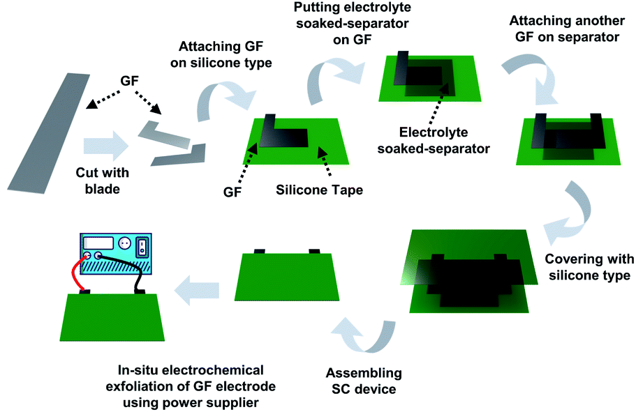 | ||
| Fig. 1 Schematic illustration of in situ exfoliation of graphite foil and deposition of MnO2 in an assembled supercapacitor device. | ||
In this study, a facile method to increase the surface area of the graphite foil electrode by in situ electro-chemically exfoliating graphite foil after assembling the supercapacitor device composed of electrode and electrolyte-soaked membrane. This simple method increases the specific capacitance and energy density of the supercapacitor device. An asymmetric supercapacitor device was fabricated simply via addition of metal salt to the electrolyte. Amorphous MnO2 nanoparticles were deposited onto the graphite foil electrode according to the above electrochemical exfoliation procedure. As a result, we produced an effective electrochemical supercapacitor with high energy and power density.
A supercapacitor device was fabricated using graphite foil, and an overvoltage was applied to the fabricated device to exfoliate the graphite electrode in situ (Fig. 1).9,14 In detail, as-made graphite foil was cut into the desired shape using a blade. The cut electrode was attached to silicone tape, and 1 M potassium nitrate (KNO3)-soaked cellulose paper was placed on top. After replacing the electrode, the supercapacitor device was assembled using silicone tape. The silicone tape was stripped off to a size of 2 mm by 2 mm to vent the gases produced in the assembled device. Using a power supply, a voltage was applied to a GF electrode in a step-wise sequence at 3.0 V for 30 minutes, 4.0 V for 10 minutes, and 5.0 V for 5 minutes (the first anodic exfoliation). After that, the same voltage sequence was applied to another GF electrode (the second anodic exfoliation). This method fabricates a symmetric device composed of an exfoliated graphite foil (EGF) anode and an EGF cathode. To manufacture a hybrid-type device composed of an EGF anode and manganese(IV) oxide (MnO2)-deposited-exfoliated graphite foil (MEGF) cathode, the above process was repeated using a mixture of 1 M KNO3 and 10 mM manganese acetate (Mn(OAc)2) as the electrolyte instead of KNO3. The Mn salt is converted to MnO2 by anodic oxidation on the electrode.9,16
The electrochemically exfoliated GF devices containing KNO3 electrolyte or KNO3 with Mn(OAc)2 electrolyte were disassembled to analyze the characteristics of the electrode.
The mass of EGF and MEGF electrodes were 18 mg cm−2 and 25 mg cm−2, respectively. The scanning electron microscopy (SEM) images show that the smooth surface of the GF electrode (Fig. 2a) became rough even after electrochemical exfoliation in the assembled device (Fig. 2b). In the electrolyte containing Mn salt, spherical particles were shown on the second anodic exfoliated graphite surface (Fig. 2c) but not in the first anodic exfoliated graphite electrode. At the first anodic exfoliation of GF, MnO2 spherical particles were grown on the exfoliated graphite surface. After that, MnO2 spherical particles were also grown on another exfoliated graphite electrode surface during the second anodic exfoliation of GF. However, MnO2 particles formed in the first anodic exfoliation step were dissolved into the electrolyte solution by cathodic reduction from insoluble Mn4+ oxide to soluble Mn2+ salt17 during the second anodic exfoliation step.
 | ||
| Fig. 2 FE-SEM images of (a) GF, (b) EGF, and (c) MEGF. (d) XPS spectra of C 1s of GF, EGF, and MEGF. (e) XPS spectra of Mn 2p of MEGF. (f) XRD patterns of GF, EGF, and MEGF. | ||
The X-ray photoelectron spectroscopy (XPS) (Fig. 2d) shows the GF electrode consists of almost all sp2-type carbon from the peak of binding energy at 284.6 eV. For the XPS spectrum of the EGF electrode, a peak of C–O binding energy at 286.4 eV is observed with a sp2-carbon peak of binding energy at 284.6 eV, which indicates that the EGF electrode was oxidized by electrochemical exfoliation.18 The XPS spectrum of the MEGF electrode shows similar results that of the EGF in the peak position of the C 1s of the XPS spectrum and of peaks at 641.9 eV and 653.7 eV corresponding to Mn 2p3/2 binding energy and Mn 2p1/2 binding energy, respectively19 (Fig. 2e). These results show that Mn-containing spherical particles were grown on the EGF surface.
The X-ray diffraction (XRD) pattern (Fig. 2f) of the GF electrode shows a distinct sharp peak at 2θ = 26.5° with a d-spacing that corresponds to 3.36 Å and at 2θ = 54.6° for the GF, close to that of the graphite (002) and (004) peaks.14 For the EGF and MEGF electrodes, the XRD peaks corresponding to the graphite (002) and (004) broadens, and the peak at 2θ = 12.2° with d-spacing of ca. 7.25 Å is similar to that of graphene oxide (001).14 These results suggest that graphite was exfoliated and oxidized through electrochemical exfoliation in the assembled device. Also, the MEGF electrode has the XRD peaks at 2θ = 36.8° and 65.8°, correspond to that of the amorphous phase of MnO2 (006) and (110) peaks, respectively, (Fig. 2f inset) demonstrating that MnO2 particles were successfully deposited on the EGF electrode.20
A three-electrode experiment was conducted to evaluate the electrochemical properties of the fabricated electrode. The three-electrode configuration was composed of the prepared electrodes connected to a Pt wire as working electrode, a porous Pt plate as a counter electrode, and Ag/AgCl as a reference electrode in a 1 M KNO3 electrolyte solution.
When cyclic voltammetry (CV) curves of the electrodes were measured at a potential ranging from −0.8 to +0.2 V (vs. Ag/AgCl)21 and a scan rate of 10 mV s−1, the GF and EGF electrodes show areal capacitance of 44.4 mF cm−2 and 756 mF cm−2, respectively22 (Fig. 3a). With Brunauer–Emmett–Teller (BET) analysis, the surface area increased from 17.1 m2 g−1 for the GF electrode to 33.5 m2 g−1 for the EGF electrode. These results confirm that the areal capacitance of the GF was about 17 times improved by the simple in situ electrochemical exfoliation method. The CV curves of the MEGF electrode were measured at a potential ranging from +0.2 to +1.2 V (vs. Ag/AgCl)21 and a scan rate of 10 mV s−1 and show an areal capacitance of 563 mF cm−2, which suggest that the in situ electrochemical exfoliation method was effective to increase the areal capacitance of GF in the Mn-containing electrolyte solution (Fig. 3b). Even as the scan speed is increased from 10 mV s−1 to 100 mV s−1, both the EGF and the MEGF electrodes show stable operation in the general potential window range without any significant original shape distortion. The galvanostatic charge–discharge (GCD) curves of the EGF and the MEGF electrodes were produced to further study the electrochemical properties at various current densities.
 | ||
| Fig. 3 CV curves of (a) the EGF and (b) MEGF in three-electrode system at various scan rates. GCD curves of (c) EGF and (d) MEGF at various current densities. (e) Areal capacitance of the electrodes at different current densities. (f) EIS analysis of the electrodes. | ||
In the EGF electrode, GCD curves show a linear form that results from the electric double layer capacitor (EDLC) type behavior9 (Fig. 3c). The GCD curves of the MEGF electrode show a non-linear shape of pseudocapacitive behavior that resulted from the surface-confined faradaic reaction of the active materials (Fig. 3d).19 Due to the increased surface area and pseudocapacitive contribution, the areal capacitance of the EGF and MEGF electrodes calculated from the GCD curve was 223 mF cm−2 and 98.9 mF cm−2, respectively, at a current density of 5 mA cm−2. Even at a high current density of 50 mA cm−2, the areal capacitances of EGF and MEGF electrodes were 112 mF cm−2 and 32.6 mF cm−2, respectively (Fig. 3e).
Electrochemical impedance spectroscopy (EIS) of the GF, EGF, and MEGF electrodes was conducted in the frequency range from 1 MHz to 0.01 Hz with an alternating current (AC) perturbation of 10 mV (Fig. 3f). At high frequencies, the GF, EGF, and MEGF electrodes equivalent series resistance (ESR) of 1.22 Ω, 1.54 Ω, and 3.16 Ω, respectively, and undetectable charge transfer resistance (Rct).23 These results are due to the low resistance of the conductive GF electrode and compact adhesion between the GF electrode and exfoliated graphite or MnO2 particles. At low frequencies, the EGF and MEGF electrodes show capacitive behavior that appeared as a vertical increase in the imaginary parts of impedance, generally indicating ideal capacitance compared with the GF electrode.24 These results show that the GF electrode had better capacitive behavior after electrochemical exfoliation in KNO3 or Mn salt-added KNO3 electrolyte.
Based on the results of the three-electrode experiment, the performance of the device manufactured in situ was measured. When cyclic voltammetry (CV) curves of the electrodes were measured at a voltage ranging from 0 to +1.0 V and a scan rate of 10 mV s−1, the GF//GF device shows areal capacitance of 35.6 mF cm−2; after electrochemical exfoliation, the EGF//EGF device shows areal capacitance of 604 mF cm−2 (Fig. 4a). These results confirm that the areal capacitance of the GF//GF device was about 17 times improved by the simple in situ electrochemical exfoliation method. The CV curves of the EGF//MEGF electrode were measured at a wider voltage window to +2.0 V because the operating voltage window is determined by the sum of work function difference and surface polarization of positive and negative electrodes.21 The CV curves of the EGF//MEGF device were measured at a voltage ranging from 0 to +2.0 V and a scan rate of 10 mV s−1 and show areal capacitance of 535 mF cm−2 (Fig. 4b and c). Both the EGF//EGF device and EGF//MEGF device show stable operation without significant original shape distortion when the scan speed was increased from 10 mV s−1 to 100 mV s−1. In the EGF//EGF device, GCD curves are linear (Fig. 4d); those of the EGF//MEGF device are non-linear (Fig. 4e). The areal capacitance of the EGF//EGF and EGF//MEGF devices calculated from the GCD curve were 355 mF cm−2 and 405 mF cm−2, respectively, at a current density of 2 mA cm−2. Even at a high current density of 20 mA cm−2, the areal capacitances of the EGF//EGF and EGF//MEGF devices were 169 mF cm−2 and 94.6 mF cm−2, respectively (Fig. 4f). Even after in situ exfoliation and modification of GF in the devices, these characteristics were highly improved for use as supercapacitor devices.
 | ||
| Fig. 4 CV curves of (a) the EGF//EGF and (b) EGF//MEGF device with scan rates. (c) CV curves of the EGF//MEGF device with various cell voltages. GCD curves of (d) EGF//EGF device and (e) EGF//MEGF device at various current densities. (f) Areal capacitance of the EGF//EGF and EGF//MEGF device at different current densities. | ||
The EIS of the EGF//EGF device and EGF//MEGF device was examined in the same condition as that of the electrodes. At high frequencies, the GF//GF device, EGF//EGF device, and EGF//MEGF device show ESR of 3.56 Ω, 5.54 Ω, and 8.17 Ω, respectively, and the Rct of undetectable value, 1.43 Ω, and 3.85 Ω, respectively (Fig. 5a). Compared to the electrodes, these values are slightly increased due to the rigid cellulose separator that could not conformally contact the separator and electrodes. However, at low frequencies, the EGF//EGF device and EGF//MEGF device showed a vertical increase in the imaginary parts of impedance, which generally indicates ideal capacitive behavior.24
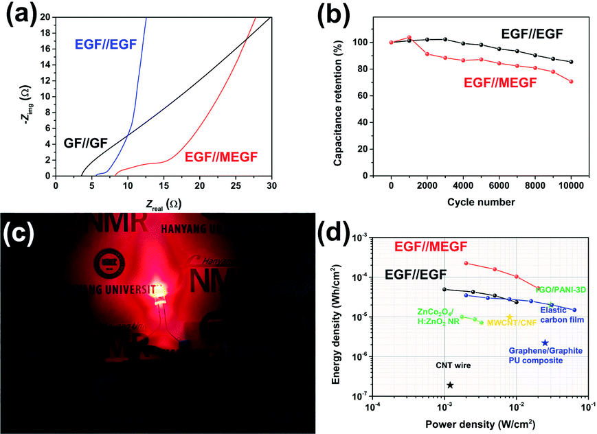 | ||
| Fig. 5 (a) EIS analysis of the devices. (b) Long-term cycling test of the devices with a current density of 50 mA cm−2. (c) Digital photograph of the EGF//MEGF device lightning red LED. (d) Ragone plot of the EGF//EGF and EGF//MEGF device compared to various supercapacitor devices. | ||
Long-term charge and discharge tests were conducted to explore the electrochemical stabilities of the device with a current density of 50 mA cm−2 for 10![[thin space (1/6-em)]](https://www.rsc.org/images/entities/char_2009.gif) 000 cycles (Fig. 5b). The areal capacitance of the EGF//EGF device and EGF//MEGF device retained 85% and 71% of the initial value, respectively, indicating good electrochemical stability.
000 cycles (Fig. 5b). The areal capacitance of the EGF//EGF device and EGF//MEGF device retained 85% and 71% of the initial value, respectively, indicating good electrochemical stability.
The in situ electrochemical exfoliation and modification method is applied simply to practical energy storage devices. To demonstrate the application, the EGF//MEGF device was used as a power source of a red-light emitting diode (LED). After charging at applying 2.0 V for 10 minutes, the device was connected to the 1.8 V red LED and successfully showed red-light illumination (Fig. 5c). Notably, a single hybrid-type supercapacitor could operate the red LED, which showed that our device obtains sufficient operating voltage and energy capacity.
After calculating of the power density and energy density of each device from GCD curves,22 these results were plotted on a Ragone plot and used to compare the energy density and power density of our devices with those of other supercapacitors25–30 (Fig. 5d). At a current density of 2 mA cm−2, the energy density of the EGF//EGF device was 49 μW h cm−2 with a power density of 1.0 mW cm−2. At current density was increased to 20 mA cm−2, energy density decreased to 24 μW h cm−2, while power density increased to 10 mW cm−2. In the EGF//MEGF device, the energy density was 0.23 mW h cm−2 with a power density of 2.0 mW cm−2. As current density was increased to 20 mA cm−2, energy density decreased to 53 μW h cm−2 while power density increased to 20 mW cm−2. At a low current density, the EGF//MEGF device has a higher energy density than the EGF//EGF device. Because pseudo-active materials, for example, MnO2 in the EGF//MEGF device offer supplementary pseudocapacitance based on the electrochemical redox reaction to carbon-like-materials, for example, graphite in the EGF//EGF device.31,32 However, the energy density of the EGF//MEGF device is more attenuated than that of the EGF//EGF device at a high current density up to 20 mA cm−2. From the EIS plot of devices (Fig. 5a), the EGF//EGF device showed lower ESR, and Rct than the EGF//MEGF device, indicating the more efficient solution diffusion and electron transfer in the EGF//EGF device than EGF//MEGF device. Besides, the slope of the EGF//EGF device is steeper than that of the EGF//MEGF device, revealing the more superior ion-transport rate of electrolyte-ions in the EGF//EGF device than the EGF//MEGF device.33
Nevertheless, the energy and power density of our devices were higher than those of many other supercapacitors, attributed to the reduced resistance, high areal capacitance, and extended operating voltage of our devices.
Therefore, the simple fabrication method, in situ electrochemically exfoliated and modified GF in the assembled device, produced supercapacitor devices that exhibited superior performance and substantial promise for energy storage applications.
Conclusions
In summary, we simply fabricated high-performance supercapacitor devices using in situ electrochemical exfoliation and modification of GF in assembled devices. The areal capacitance of the EGF//EGF and EGF//MEGF device reached 355 mF cm−2 and 405 mF cm−2, respectively, at a current density of 2 mA cm−2. As current density increased to 20 mA cm−2, the areal capacitance retained 47.6% for the EGF//EGF device and 23.4% for the EGF//MEGF device, respectively, of these initial values. With small resistance and high areal capacitance, the EGF//EGF device shows high energy and power density of 24–49 μW h cm−2 and 1.0–10 mW cm−2, respectively. In addition, such a wide operating voltage resulted in the remarkable energy density and power density of 53 μW h cm−2 to 0.23 mW h cm−2 and 2.0 to 20 mW cm−2, respectively, for the EGF//MEGF device. The energy density and power density were better than those of many supercapacitor devices. Also, long-term charge and discharge tests revealed excellent electrochemical stabilities. The method, in situ electrochemically exfoliated and modified GF in the assembled device, shows substantial promise to simply fabricate supercapacitor devices that which exhibit superior performance for energy storage applications. These results can be attributed to the microstructure and electrochemistry of the materials in the electronic devices prepared by the in situ electrochemical reaction.Conflicts of interest
There are no conflicts to declare.Acknowledgements
This research was supported by Nano Material Technology Development Program through the National Research Foundation of Korea (NRF) funded by the Ministry of Science, ICT and Future Planning (No. 2016M3A7B4900044). This work was supported by the National Research Foundation of Korea (NRF) grant funded by the Korea government (MSIT) (No. 2015R1A5A1037548). In addition, this work was supported by the Technology Innovation Program (20004041, Isotropic 15W composite Thermal Interface Material development for EV ECU unit using Boron nitride application) funded By the Ministry of Trade, Industry& Energy (MOTIE, Korea).Notes and references
- F. R. McLarnon and E. J. Cairns, Annu. Rev. Energy, 1989, 14, 241–271 CrossRef
.
- P. Baudry, S. Lascaud, H. Majastre and D. Bloch, J. Power Sources, 1997, 68, 432–435 CrossRef CAS
- Y. Li and H. Dai, Chem. Soc. Rev., 2014, 43, 5257–5275 RSC
- M. Winter and R. J. Brodd, Chem. Rev., 2004, 104, 4245–4270 CrossRef CAS
- A. S. Aricò, P. Bruce, B. Scrosati, J.-M. Tarascon and W. van Schalkwijk, Nat. Mater., 2005, 4, 366–377 CrossRef
- P. Simon and Y. Gogotsi, Nat. Mater., 2008, 7, 845–854 CrossRef CAS
- Y. Gogotsi and P. Simon, Science, 2011, 334, 917–918 CrossRef CAS
- M. D. Stollera and R. S. Ruoff, Energy Environ. Sci., 2010, 3, 1294–1301 RSC
- Y. Song, T.-Y. Liu, G.-L. Xu, D.-Y. Feng, B. Yao, T.-Y. Kou, X.-X. Liu and Y. Li, J. Mater. Chem. A, 2016, 4, 7683–7688 RSC
- S. Akbulut, M. Yilmaz, S. Raina, S.-H. Hsu and W. P. Kang, J. Appl. Electrochem., 2017, 47, 1035–1044 CrossRef CAS
- M. Arvania, J. Keskinena, D. Lupoa and M. Honkanen, J. Energy Storage, 2020, 29, 101384 CrossRef
- O. N. Shornikova, E. V. Kogan, N. E. Sorokina and V. V. Avdeev, Russ. J. Phys. Chem. A, 2009, 83, 1022–1025 CrossRef CAS
- J. M. Munuera, J. I. Paredes, M. Enterría, A. Pagán, S. Villar-Rodil, M. F. R. Pereira, J. I. Martins, J. L. Figueiredo, J. L. Cenis, A. Martínez-Alonso and J. M. D. Tascón, ACS Appl. Mater. Interfaces, 2017, 9, 24085–24099 CrossRef CAS
- J. Cao, P. He, M. A. Mohammed, X. Zhao, R. J. Young, B. Derby, I. A. Kinloch and R. A. W. Dryfe, J. Am. Chem. Soc., 2017, 139, 17446–17456 CrossRef CAS
- Y. Zhang, Y. Xu, J. Zhu, L. Li, X. Du and X. Sun, Carbon, 2018, 127, 392–403 CrossRef CAS
- Y. Saito, M. Meguro, M. Ashizawa, K. Waki, R. Yuksel, H. E. Unaland and H. Matsumoto, RSC Adv., 2017, 7, 12351–12358 RSC
- V. Mathew, B. Sambandam, S. Kim, S. Kim, S. Park, S. Lee, M. H. Alfaruqi, V. Soundharrajan, S. Islam, D. Y. Putro, J.-Y. Hwang, Y.-K. Sun and J. Kim, ACS Energy Lett., 2020, 5, 2376–2400 CrossRef CAS
- L. Dong, Z. Chen, X. Zhao, J. Ma, S. Lin, M. Li, Y. Bao, L. Chu, K. Leng, H. Lu and K. P. Loh, Nat. Commun., 2018, 9, 76 CrossRef
- J. Noh, C.-M. Yoon, Y. K. Kim and J. Jang, Carbon, 2017, 116, 470–478 CrossRef CAS
- B. J. Kang, J.-B. Joo, J. K. Lee and W. Choi, J. Electroanal.
Chem., 2014, 728, 34–40 CrossRef CAS
- Y. Shao, M. F. El-Kady, J. Sun, Y. Li, Q. Zhang, M. Zhu, H. Wang, B. Dunn and R. B. Kaner, Chem. Rev., 2018, 118, 9233–9280 CrossRef CAS
- J. Yan, Z. Fan, W. Sun, G. Ning, T. Wei, Q. Zhang, R. Zhang, L. Zhi and F. Wei, Adv. Funct. Mater., 2012, 22, 2632–2641 CrossRef CAS
- B.-A. Mei, O. Munteshari, J. Lau, B. Dunn and L. Pilon, J. Phys. Chem., 2018, 122, 194–206 CrossRef CAS
- J.-G. Wang, Y. Yang, Z.-H. Huang and F. Kang, J. Power Sources, 2013, 224, 86–92 CrossRef CAS
- V. T. Le, H. Kim, A. Ghosh, J. Kim, J. Chang, Q. A. Vu, D. T. Pham, J.-H. Lee, S.-W. Kim and Y. H. Lee, ACS Nano, 2013, 7, 5940–5947 CrossRef CAS
- N. Hu, L. Zhang, C. Yang, J. Zhao, Z. Yang, H. Wei, H. Liao, Z. Feng, A. Fisher, Y. Zhang and Z. J. Xu, Sci. Rep., 2016, 6, 19777 CrossRef CAS
- B. D. Boruah, A. Maji and A. Misra, Nanoscale, 2017, 9, 9411–9420 RSC
- L. Manjakkal, W. T. Navaraj, C. G. Núñez and R. Dahiya, Adv. Sci., 2019, 6, 1802251 CrossRef
- M. K. Jha, K. Hata and C. Subramaniam, ACS Appl. Mater. Interfaces, 2019, 11, 18285–18294 CrossRef CAS
- P. Huang, C. Lethien, S. Pinaud, K. Brousse, R. Laloo, V. Turq, M. Respaud, A. Demortière, B. Daffos, P. L. Taberna, B. Chaudret, Y. Gogotsi and P. Simon, Science, 2016, 351, 691–695 CrossRef CAS
- Y. Wang, Y. Song and Y. Xia, Chem. Soc. Rev., 2016, 45, 5925–5950 RSC
- L. Miao, Z. Song, D. Zhu, L. Li, L. Gan and M. Liu, Mater. Adv., 2020, 1, 945–966 RSC
- L. Miao, H. Duan, D. Zhu, Y. Lv, L. Gan, L. Li and M. Liu, J. Mater. Chem. A, 2021 10.1039/D0TA09985F
Footnote |
| † Electronic supplementary information (ESI) available. See DOI: 10.1039/d0ra10533c |
| This journal is © The Royal Society of Chemistry 2021 |