
 Open Access Article
 This Open Access Article is licensed under a Creative Commons Attribution-Non Commercial 3.0 Unported Licence
Improving the performance of quantum-dot light-emitting diodes via an organic–inorganic hybrid hole injection layer†
Jae Seung Shinab,
Tae Yeon Kimab,
Su Been Heoab,
Jong-Am Hongc,
Yongsup Park cd and
Seong Jun Kang*ab
cd and
Seong Jun Kang*ab
aDepartment of Advanced Materials Engineering for Information and Electronics, Kyung Hee University, Yongin 17104, Republic of Korea. E-mail: junkang@khu.ac.kr; Tel: +82-31-201-3324
bIntegrated Education Program for Frontier Materials (BK21 Four), Kyung Hee University, Yongin 17104, Republic of Korea
cDepartment of Physics and Research Institute for Basic Sciences, Kyung Hee University, Seoul 02447, Republic of Korea
dDepartment of Information Display, Kyung Hee University, Seoul 02447, Republic of Korea
First published on 21st January 2021
Abstract
Poly(3,4-ethylenedioxythiophene):poly(styrene-sulfonate) (PEDOT:PSS) is a commonly used material for the hole injection layer (HIL) in quantum-dot light-emitting diodes (QLEDs). In this work, we improved the performance of the QLED by using an organic–inorganic hybrid HIL. The hybrid HIL was prepared by mixing PEDOT:PSS with vanadium oxide (V2O5), which is a transition-metal oxide (TMO). The hole injection properties of PEDOT:PSS were improved according to the amount of V2O5 mixed into the PEDOT:PSS. The maximum luminance and current efficiency were 36![[thin space (1/6-em)]](https://www.rsc.org/images/entities/char_2009.gif) 198 cd m−2 and 13.9 cd A−1, respectively, when the ratio of PEDOT:PSS and V2O5 was 10:1. Moreover, the operating lifetime exceeded 300 h, which is 10 times longer than the lifetime of the device with only PEDOT:PSS HIL. The improvement was analyzed using ultraviolet and X-ray photoelectron spectroscopy. We found that the density of state (DOS) of PEDOT:PSS near the Fermi energy level was increased by mixing V2O5. Therefore, the increase of DOS improved the hole injection and the performance of QLEDs. The result shows that the hybrid HIL can improve the performance and the stability of QLEDs.
198 cd m−2 and 13.9 cd A−1, respectively, when the ratio of PEDOT:PSS and V2O5 was 10:1. Moreover, the operating lifetime exceeded 300 h, which is 10 times longer than the lifetime of the device with only PEDOT:PSS HIL. The improvement was analyzed using ultraviolet and X-ray photoelectron spectroscopy. We found that the density of state (DOS) of PEDOT:PSS near the Fermi energy level was increased by mixing V2O5. Therefore, the increase of DOS improved the hole injection and the performance of QLEDs. The result shows that the hybrid HIL can improve the performance and the stability of QLEDs.
1. Introduction
Quantum-dots (QDs) have unique electrical and optical properties. This makes them attractive for optoelectronics such as light-emitting diodes (LEDs), photodetectors, and solar cells.1–3 Due to the quantum confinement effect, QDs have a size-dependent emission wavelength, narrow emission spectrum and high quantum yields (QY).4,5 Additionally, quantum-dot light-emitting diodes (QLEDs), including these QD emitters, enable a low-cost fabrication and exhibit a narrower emission spectrum and higher color purity than organic light-emitting diodes.6,7 Therefore, QLEDs have been intensively studied as a candidate for next-generation displays.8Meanwhile, poly(3,4-ethylenedioxythiophene):poly(styrene-sulfonate) (PEDOT:PSS) is a commonly used material for hole injection layers (HILs). PEDOT:PSS has high work function and high transparency, so it is suitable for use as a HIL for light-emitting diodes.9–11 However, PEDOT:PSS has drawbacks as well. Most notably, its corrosive, acidic and hygroscopic properties can severely limit device performance.12,13 To overcome these drawbacks in the field of optoelectronics such as LEDs and photovoltaics, bilayer PEDOT:PSS14,15 and transition-metal oxide doped PEDOT:PSS16–19 have been used in the device. Transition-metal oxides, such as nickel oxide (NiO), molybdenum oxide (MoO3), tungsten oxide (WO3), copper oxide (CuO), and vanadium oxide (V2O5), are inorganic materials that can be used in various optoelectronics due to their high stability to heat, hydrogen, and oxygen.20,21 Therefore, organic–inorganic hybrid HIL could be used to improve QLEDs with a high stability.
In this work, we have studied organic–inorganic hybrid HIL by mixing V2O5 into the PEDOT:PSS to improve the performance of QLEDs. The advantages of introducing hybrid HIL are that it can be easily fabricated with a single layer while improving the disadvantages of the organic layer. The injection efficiency of V2O5 mixed PEDOT:PSS HIL was better than PEDOT:PSS only HIL. Therefore, the performance of QLEDs was improved. Moreover, the stability of the device was improved due to the inorganic mixture of V2O5. Ultraviolet and X-ray photoelectron spectroscopy (UPS & XPS) were used to find the origin of the improvement. Therefore, we suggest an organic–inorganic hybrid HIL for the high-performance QLEDs.
2. Experimental
2.1 Materials
The PEDOT:PSS (CLEVIOS™ P VP AI4083) was purchased from Heraeus. Vanadium(V) triisopropoxide oxide (96%) was purchased from Alfa Aesar. The structural formulas of the PEDOT:PSS and vanadium(V) triisopropoxide oxide are shown in Fig. S1.† Poly[(9,9-dioctylfluorenyl-2,7-diyl)-co-(4,4′-(4-sec-butylphenyl)diphenylamine)] (TFB) was purchased from Lumtec. Green QD with the chemical composition of CdSe/ZnS was obtained from UNIAM, while ZnO (N-10) was purchased from Avantama (Switzerland). All commercial materials were used in the state in which they were received.2.2 Preparation of V2O5 mixed PEDOT:PSS solution
Vanadium(V) triisopropoxide oxide (96%) was first dissolved in isopropyl alcohol and then a drop of deionized water (DI water) was added for hydrolysis to prepare a 1 wt% concentration V2O5 solution. The volume ratios of PEDOT:PSS and V2O5 were 20:1, 10:1, and 5:1 and stirred for 12 h. Prior to use, the solution was filtered using 0.45 μm hydrophilic filter to remove unwanted particles.
2.3 QLED fabrication
Patterned indium-tin-oxide (ITO) glass substrates were first cleaned sequentially with DI water, acetone and isopropyl alcohol in an ultra-sonicator for 15 min. After cleaning, the substrates were treated with ultraviolet-ozone for 15 min to increase the hydrophilicity and work function of the ITO surface. The V2O5 was then mixed into PEDOT:PSS films and spin-coated onto the ITO at 4000 rpm for 30 s, and then annealed at 150 °C for 15 min. TFB film was spin-coated onto the HIL at 3000 rpm for 30 s, followed by annealing at 180 °C for 30 min. The green QDs film was spin-coated onto the hole transport layer (HTL) at 1500 rpm for 60 s, followed by annealing at 60 °C for 10 min. The ZnO film was spin-coated onto the emitting layer (EML) at 2000 rpm for 60 s, followed by annealing at 60 °C for 10 min. The entire procedure was carried out under ambient condition. Finally, 130 nm-thick layer of aluminum (Al) was deposited using thermal evaporator.2.4 Characterization
UPS and XPS spectra were obtained using photoelectron spectrometer (KRATOS AXIS NOVA) with ultraviolet (He I) and X-ray (Al Kα) light sources. The transmittance spectra were taken by an UV-vis spectrophotometer (JASCO, V-570). The current–voltage–luminance (I–V–L) characteristics and electroluminescence (EL) spectra QLEDs were measured using the I–V–L measurement system (M6100, McScience) coupled with a Keithley 2400 source meter and Konica Minolta CS-2000 spectroradiometer.3. Results and discussion
The UPS valence band spectra of bare ITO, ITO/PEDOT:PSS, ITO/PEDOT:PSS:V2O5 (10:1), ITO/PEDOT:PSS/TFB and ITO/PEDOT:PSS:V2O5 (10:1)/TFB are summarized in Fig. 1(a). The left side of Fig. 1(a) is the secondary electron cutoff (SEC) region, and the right side is the valence region. The work function of ITO was measured as 4.44 eV. The highest occupied molecular orbital (HOMO) level of TFB on PEDOT:PSS was located at 0.86 eV below the Fermi energy level (EF). Meanwhile, the HOMO level of TFB on V2O5 mixed PEDOT:PSS was located at 0.88 eV below EF. Therefore, the hole injection barrier heights are similar in both cases of TFB on PEDOT:PSS and TFB on V2O5 mixed PEDOT:PSS. However, the density of state (DOS) near the EF of PEDOT:PSS and V2O5 mixed PEDOT:PSS are different. The spectrum area near the EF represents the number of DOS at the valence region. As shown in the inset of Fig. 1(a), the spectrum area increased 33% when V2O5 has been mixed into the PEDOT:PSS. Therefore, we can assume that the charge transport of V2O5 mixed PEDOT:PSS increases compared to the PEDOT:PSS due to the increase of DOS, which is originated from the V2O5. Fig. 1(b) and (c) shows the interfacial energy level diagrams of ITO/PEDOT:PSS/TFB and ITO/PEDOT:PSS:V2O5 (10:1)/TFB. The band gap of the TFB film was calculated using Tauc's plot from the UV-vis transmission spectra, as shown in Fig. S2.†
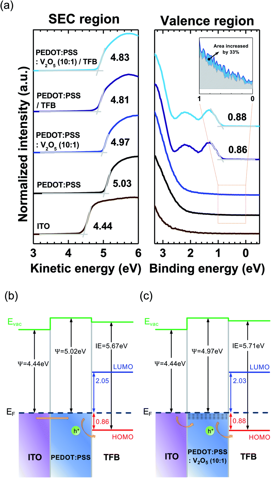 | ||
| Fig. 1 (Color online) (a) UPS spectra of ITO, ITO/HILs and ITO/HILs/TFB measured near the SEC (left) and EF region (right). The inset represents the area under the UPS spectra near the EF of PEDOT:PSS (gray) and PEDOT:PSS:V2O5 (10:1) (blue). Interfacial energy level diagram of (b) ITO/PEDOT:PSS/TFB and (c) ITO/PEDOT:PSS:V2O5 (10:1)/TFB. | ||
Fig. 2 shows the XPS spectrum of the V 2p core level of PEDOT:PSS:V2O5 (10:1) film. The V 2p3/2 core level can be separated into V5+ (516.93 eV) and V4+ (515.41 eV) oxidation states by Lorentzian–Gaussian fitting.22 The dominant V5+ state corresponds to vanadium pentoxide (V2O5), while the V4+ state represents vanadium dioxide (VO2).23,24 The V4+ oxidation state was formed by reducing the V2O5 layer via exposure to air.22 The peak intensity of the V4+ state in PEDOT:PSS:V2O5 (10:1) is small due to the small amount of VO2, which is contained in the V2O5 mixed PEDOT:PSS HIL. The V4+ oxidation state indicates a state close to EF, which leads the improvement of the hole injection characteristics.
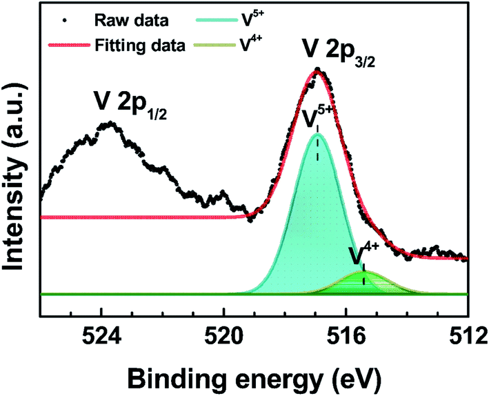 | ||
| Fig. 2 (Color online) Measured XPS spectrum of the V 2p core level of the PEDOT:PSS:V2O5 film. | ||
The hole only devices (HODs, ITO/HIL/TFB/Al) were fabricated and evaluated to observe the hole injection and transport behavior of HIL with various concentrations of V2O5 into PEDOT:PSS, as shown in Fig. 3(a). The thickness change was not large with the increase of the V2O5 mixing ratio. The thickness of the pristine PEDOT:PSS and V2O5 mixed PEDOT:PSS layer is about 35–37 nm.19 Electron only device (EOD, ITO/ZnO/Al) was also fabricated to evaluate the electron injection and transport behavior. The current density of V2O5 mixed PEDOT:PSS HIL showed higher current density value than that of PEDOT:PSS HIL, as we can expected from the interfacial electronic structure of Fig. 1(b) and (c). Among the various concentration of V2O5 into the PEDOT:PSS, PEDOT:PSS:V2O5 (10:1) film shows the highest current density. Therefore, the charge balance between PEDOT:PSS:V2O5 (10:1) HIL and ZnO ETL would be best. The transmittance of the PEDOT:PSS and V2O5 mixed PEDOT:PSS have been measured as shown in Fig. 3(b). All films were prepared onto the glass substrate. The transmittance of PEDOT:PSS is slightly increased according to mix the V2O5 into the PEDOT:PSS. The transmittance was over 98.3% in the 530 to 540 nm region, as shown in the inset of Fig. 3(b).
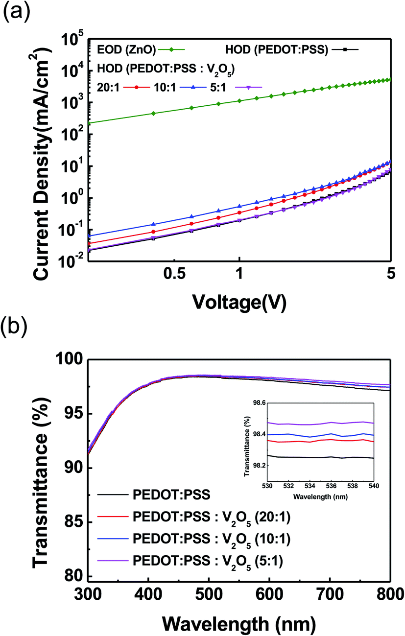 | ||
| Fig. 3 (Color online) (a) Current density–voltage (J–V) characteristics of the HODs (ITO/HIL/TFB/Al) and EOD (ITO/ZnO/Al). (b) Transmittance of different HIL films on glass substrate. The inset shows the transmittance in the range of 530 to 540 nm. | ||
Fig. 4 shows the light emitting performance of QLEDs with PEDOT:PSS HIL and V2O5 mixed PEDOT:PSS HIL. Fig. 4(a) shows the luminance–voltage characteristics of QLEDs. All QLEDs with a PEDOT:PSS:V2O5 HIL show a lower turn-on voltage than the QLED with PEDOT:PSS HIL. The device with PEDOT:PSS:V2O5 (10:1) showed the highest luminance of 36198 cd m−2. Fig. 4(b) shows the current density–voltage characteristics of QLEDs. A schematic diagram of the QLEDs is shown in the inset of Fig. 4(b). The current density of the devices with V2O5 mixed PEDOT:PSS HIL was lower than that of the device with PEDOT:PSS HIL, which owes to a reduction in the leakage current of the devices. The measured performance data of the devices are summarized in detail in Table 1.
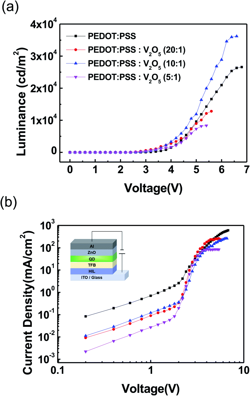 | ||
| Fig. 4 (Color online) (a) Luminance–voltage (L–V) curves of the QLED devices. (b) J–V characteristics of the QLED devices with different HIL. The inset shows the schematic diagram of QLED device. | ||
| Devices with different HIL | Vturn-on (V) (@1 cd m−2) | Lmax (cd m−2) | CEmax (cd A−1) | EQEmax (%) | T50 (h) (L0 = 100 cd m−2) | CIE 1931 (x, y) |
|---|---|---|---|---|---|---|
| PEDOT:PSS | 2.33 | 26577 |
4.6 | 1.06 | 23.9 | (0.241, 0.726) |
| PEDOT:PSS:V2O5 (20:1 v/v) |
2.06 | 12813 |
5.4 | 1.19 | — | (0.233, 0.732) |
| PEDOT:PSS:V2O5 (10:1 v/v) |
2.25 | 36198 |
13.9 | 3.18 | 301.2 | (0.231, 0.733) |
| PEDOT:PSS:V2O5 (5:1 v/v) |
2.07 | 8342 | 9.9 | 2.28 | — | (0.232, 0.733) |
Current efficiency–luminance characteristics of the QLED devices are shown in Fig. 5(a). The current efficiency of the QLEDs with PEDOT:PSS:V2O5 (10:1) HIL was measured as 13.9 cd A−1, which was significantly improved compared to the current efficiency of the device with PEDOT:PSS HIL. The improvement of the current efficiency was due to the reduction of the leakage current. Fig. 5(b) shows the EL spectra at the maximum luminance of the QLEDs. The inset shows an image of the QLEDs with PEDOT:PSS:V2O5 (10:1) HIL. The peak wavelength of QLEDs appeared at 536 nm, and the full width at half maximum (FWHM) of the QLEDs with PEDOT:PSS:V2O5 HIL was measured as ∼32 nm.
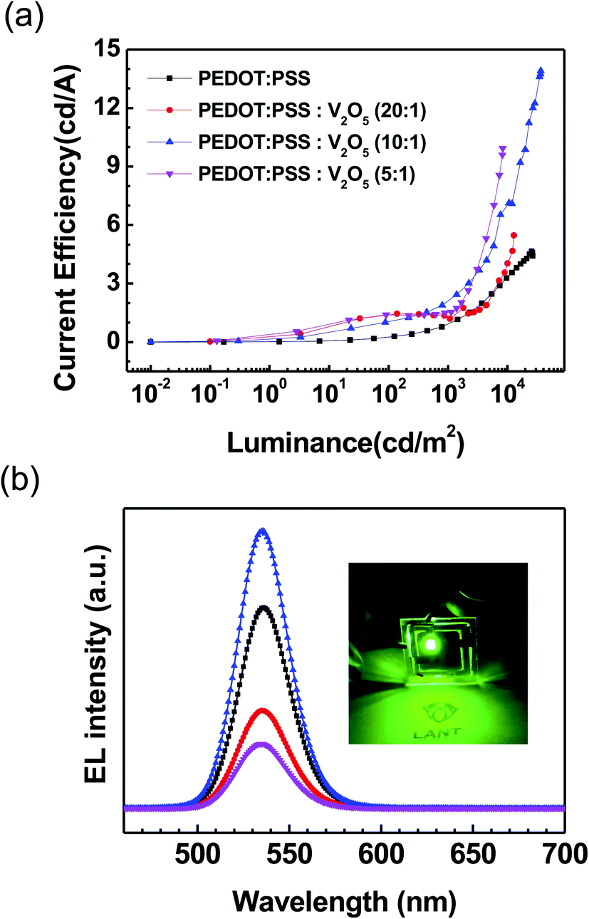 | ||
| Fig. 5 (Color online) (a) Current efficiency–luminance characteristics and (b) EL spectra of QLED devices at each maximum luminance. The inset shows an image of the device operating. | ||
Fig. 6(a) shows the lifetime measurement of the QLEDs. The measurement was conducted in a consistent current mode, and it was carried out under ambient conditions, which are room temperature, and relative humidity over ∼60%. All QLEDs were encapsulated with commercially-available epoxy resin and cover glass. The half-lifetime (T50) of the QLEDs with PEDOT:PSS HIL was measured as 0.86 h at an initial luminance (L0) of 917 cd m−2. QLEDs with PEDOT:PSS:V2O5 (10:1) HIL had a higher L0 of 1157 cd m−2, and the T50 was measured to be 7.65 h. The T50 can be extrapolated for initial luminance of 100 cd m−2 with following relation:25
| (L0)n × T50 = constant (n = 1.5), |
:1) HIL are extrapolated to be 23.9 and 301.2 h, respectively. The mixture of inorganic V2O5 significantly increased the lifetime of the devices. In addition, to characterize the emission color from the fabricated QLEDs, we plotted the Commission International de l'Eclairage (CIE) 1931 coordinate system as shown in Fig. 6(b). The CIE (x, y) coordinates were compared at the maximum luminance, and the QLED with PEDOT:PSS was measured as (0.241, 0.726), and the QLED with PEDOT:PSS:V2O5 (10:1) was measured as (0.231, 0.733). As shown in the inset of Fig. 5(b), high purity green color can be obtained due to the narrower FWHM.26,27
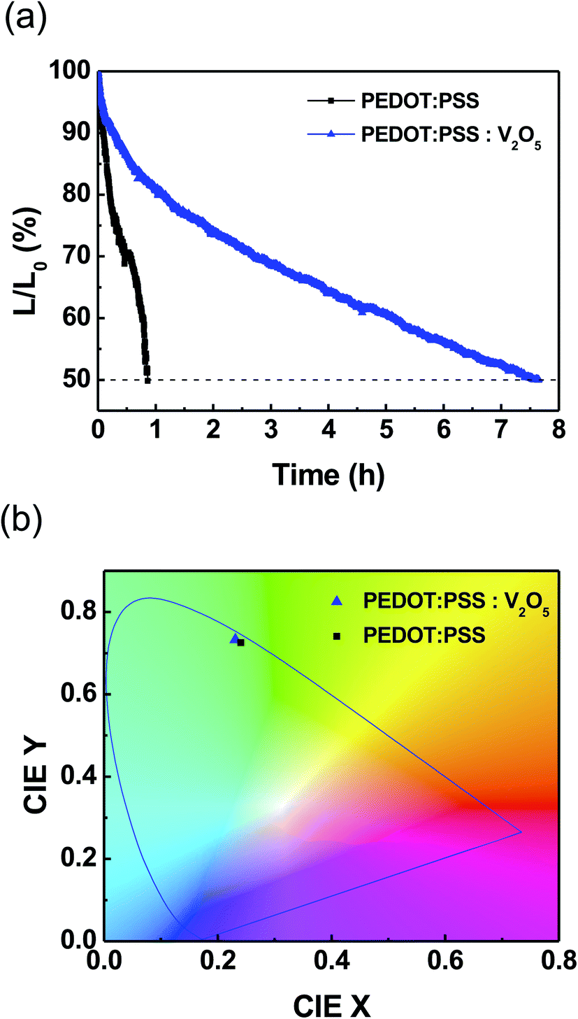 | ||
| Fig. 6 (Color online) (a) Operational lifetime and (b) CIE 1931 coordinate of QLED devices with PEDOT:PSS and PEDOT:PSS:V2O5 (10:1). | ||
4. Conclusions
In this study, we demonstrated QLEDs with V2O5 mixed PEDOT:PSS (10:1) HIL that is more efficient and more stable than a QLED with a PEDOT:PSS HIL. The hole injection property of PEDOT:PSS was improved according to mix V2O5 into PEDOT:PSS. Therefore, the maximum luminance and current efficiency of the QLEDs with V2O5 mixed PEDOT:PSS (10:1) HIL were 36198 cd m−2 and 13.9 cd A−1, respectively. Moreover, the operating lifetime exceeded 300 h, which is 10 times longer than the lifetime of the device with only PEDOT:PSS HIL. The improvement was analyzed using ultraviolet and X-ray photoelectron spectroscopy. We found that the density of state (DOS) of PEDOT:PSS near the Fermi energy level was increased by mixing V2O5. Therefore, the increase of DOS improved the hole injection and the performance of QLEDs. Our results suggest that TMO mixed PEDOT:PSS is an alternative to organic HIL for efficient and stable QLEDs.
Conflicts of interest
There are no conflicts to declare.Acknowledgements
This work was supported by a research project grant from the National Research Foundation of Korea (2020R1A6A1A03048004).References
- H. Shen, Q. Gao, Y. Zhang, Y. Lin, Q. Lin, Z. Li, L. Chen, Z. Zeng, X. Li, Y. Jia, S. Wang, Z. Du, L. S. Li and Z. Zhang, Nat. Photonics, 2019, 13, 192–197 CrossRef CAS.
- Y. Wei, Z. Ren, A. Zhang, P. Mao, H. Li, X. Zhong, W. Li, S. Yang and J. Wang, Adv. Funct. Mater., 2018, 28, 1706690 CrossRef.
- Z. Pan, H. Rao, I. Mora-Seró, J. Bisquert and X. Zhong, Chem. Soc. Rev., 2018, 47, 7659–7702 RSC.
- J. M. Pietryga, Y. S. Park, J. Lim, A. F. Fidler, W. K. Bae, S. Brovelli and V. I. Klimov, Chem. Rev., 2016, 116, 10513–10622 CrossRef CAS.
- B. O. Dabbousi, J. Rodriguez-Viejo, F. V. Mikulec, J. R. Heine, H. Mattoussi, R. Ober, K. F. Jensen and M. G. Bawendi, J. Phys. Chem. B, 1997, 101, 9463–9475 CrossRef CAS.
- V. Wood and V. Bulović, Nano Rev, 2010, 1, 5202 CrossRef.
- G. J. Supran, Y. Shirasaki, K. W. Song, J. M. Caruge, P. T. Kazlas, S. Coe-Sullivan, T. L. Andrew, M. G. Bawendi and V. Bulović, MRS Bull., 2013, 38, 703–711 CrossRef.
- M. K. Choi, J. Yang, T. Hyeon and D. H. Kim, npj Flexible Electron., 2018, 2(10), 1–14 Search PubMed.
- W. H. Kim, A. J. Mäkinen, N. Nikolov, R. Shashidhar, H. Kim and Z. H. Kafafi, Appl. Phys. Lett., 2002, 80, 3844–3846 CrossRef CAS.
- S. Kirchmeyer and K. Reuter, J. Mater. Chem., 2005, 15, 2077 RSC.
- J. Ouyang, C. W. Chu, F. C. Chen, Q. Xu and Y. Yang, Adv. Funct. Mater., 2005, 15, 203–208 CrossRef CAS.
- M. M. de Kok, M. Buechel, S. I. E. Vulto, P. van de Weijer, E. A. Meulenkamp, S. H. P. M. de Winter, A. J. G. Mank, H. J. M. Vorstenbosch, C. H. L. Weijtens and V. van Elsbergen, Phys. Status Solidi, 2004, 201, 1342–1359 CrossRef CAS.
- H. Seo, J. Lee, S. B. Heo, M. Kim, Y. Yi, S. J. Kang and H. Kim, Phys. Status Solidi, 2019, 216, 1900004 CrossRef.
- S. Shin, J. Kim, Y. H. Kim and S. I. Kim, Curr. Appl. Phys., 2013, 13, S144–S147 CrossRef.
- J. H. Yu, S. B. Heo, M. Kim, Y. Yi and S. J. Kang, Thin Solid Films, 2019, 687, 137444 CrossRef CAS.
- Y. Zhu, H. Hu, Y. Liu, X. Zheng, S. Ju, W. Lin, T. Guo and F. Li, IEEE Electron Device Lett., 2019, 40, 1147–1150 CAS.
- M. P. Zhuo, F. Liang, Y. L. Shi, Y. Hu, R. B. Wang, W. F. Chen, X. D. Wang and L. S. Liao, J. Mater. Chem. C, 2017, 5, 12343–12348 RSC.
- S. J. Lee, H. Pil Kim, A. R. bin Mohd Yusoff and J. Jang, Sol. Energy Mater. Sol. Cells, 2014, 120, 238–243 CrossRef CAS.
- J. Kim, A. Kanwat, H. M. Kim and J. Jang, Phys. Status Solidi, 2014, 212, 640–645 CrossRef.
- J. You, L. Meng, T. B. Song, T. F. Guo, Y. Yang, W. H. Chang, Z. Hong, H. Chen, H. Zhou, Q. Chen, Y. Liu, N. De Marco and Y. Yang, Nat. Nanotechnol., 2015, 11, 75–81 CrossRef.
- S. B. Heo, M. Kim, J. H. Yu, Y. Yi and S. J. Kang, Curr. Appl. Phys., 2019, 19, 657–662 CrossRef.
- J. Meyer, K. Zilberberg, T. Riedl and A. Kahn, J. Appl. Phys., 2011, 110, 033710 CrossRef.
- G. Silversmit, D. Depla, H. Poelman, G. B. Marin and R. De Gryse, J. Electron Spectros. Relat., 2004, 135, 167–175 CrossRef CAS.
- C. J. Lim, M. G. Park, M. S. Kim, J. H. Han, S. Cho, M. H. Cho, Y. Yi, H. Lee and S. W. Cho, Molecules, 2018, 23, 449 CrossRef.
- P. Wellmann, M. Hofmann, O. Zeika, A. Werner, J. Birnstock, R. Meerheim, G. He, K. Walzer, M. Pfeiffer and K. Leo, J. Soc. Inf. Disp., 2005, 13, 393 CrossRef CAS.
- R. Zhu, Z. Luo, H. Chen, Y. Dong and S. T. Wu, Opt. Express, 2015, 23, 23680 CrossRef CAS.
- J. R. Manders, L. Qian, A. Titov, J. Hyvonen, J. Tokarz-Scott, K. P. Acharya, Y. Yang, W. Cao, Y. Zheng, J. Xue and P. H. Holloway, J. Soc. Inf. Disp., 2015, 23, 523–528 CrossRef CAS.
Footnote |
| † Electronic supplementary information (ESI) available. See DOI: 10.1039/d0ra10422a |
| This journal is © The Royal Society of Chemistry 2021 |