 Open Access Article
Hierarchical Ni–Co–Mn hydroxide hollow architectures as high-performance electrodes for electrochemical energy storage†
Chengzhen Wei *ab,
Cheng Chenga,
Kaimin Wanga,
Xiaochong Lia,
Hecong Xiaoa and
Qiaofei Yaoa
aHenan Province Key Laboratory of New Opto-Electronic Functional Materials, College of Chemistry and Chemical Engineering, Anyang Normal University, Anyang 455000, P. R. China. E-mail: chengzhenweichem@126.com
bShandong Key Laboratory of Biochemical Analysis, College of Chemistry and Molecular Engineering, Qingdao University of Science and Technology, Qingdao 266042, P. R. China
First published on 23rd April 2021
Abstract
In this study, hierarchical Ni–Co–Mn hydroxide hollow architectures were successfully achieved via an etching process. We first performed the synthesis of NiCoMn-glycerate solid spheres via a solvothermal route, and then NiCoMn-glycerate as the template was etched to convert into hierarchical Ni–Co–Mn hydroxide hollow architectures in the mixed solvents of water and 1-methyl-2-pyrrolidone. Hollow architectures and high surface area enabled Ni–Co–Mn hydroxide to manifest a specific capacitance of 1626 F g−1 at 3.0 A g−1, and it remained as large as 1380 F g−1 even at 3.0 A g−1. The Ni–Co–Mn hydroxide electrodes also displayed notable cycle performance with a decline of 1.6% over 5000 cycles at 12 A g−1. Moreover, an asymmetric supercapacitor assembled with this electrode exhibited an energy density of 44.4 W h kg−1 at 1650 W kg−1 and 28.5 W h kg−1 at 12![[thin space (1/6-em)]](https://www.rsc.org/images/entities/char_2009.gif) 374 W kg−1. These attractive results demonstrate that hierarchical Ni–Co–Mn hydroxide hollow architectures have broad application prospects in supercapacitors.
374 W kg−1. These attractive results demonstrate that hierarchical Ni–Co–Mn hydroxide hollow architectures have broad application prospects in supercapacitors.
1. Introduction
Supercapacitors as special energy storage devices are commonly grouped into electrical double-layer capacitors (EDLCs) and pseudocapacitors.1 EDLCs store electrical charge derived from ions (electrostatic force) between electrode and electrolyte interfaces,2 whereas pseudocapacitors build up electrical charge through the electrode surface faradaic reactions.3 Of note, pseudocapacitors achieve high specific capacitances or energy density compared with EDLCs. Therefore, many endeavors have been concentrated on pseudocapacitors.It is demonstrated that hollow structures enable electrodes to markedly promote electrochemical activity for pseudocapacitors. Hollow interiors not only improve the electrode/electrolyte contact interface, but also strengthen the structural stability for long-life cycle, thus significantly improving the performance of electrodes.4–6 In recent years, numerous electrode materials have been explored for pseudocapacitors, among which transition metal hydroxide materials are considered to be powerful electrodes owing to their large specific capacitance, good electrochemical activity as well as low cost.7–9 In particular, ternary Ni–Co–Mn hydroxides have attracted considerable momentum, which show controllable chemical compositions and multiple redox states, and are thus regarded as admirable electrode materials for pseudocapacitors. For example, a seed-assisted route was explored for the preparation of Ni–Co–Mn hydroxide nanoflakes, delivering a large specific capacity of 1043.1 μA h cm−2 at 5.2 mg cm−2.10 Chen et al. developed a hydrothermal method to prepare amorphous Ni–Co–Mn hydroxide, which achieved a high specific capacity of 749 C g−1.11 Alternatively, a hydrothermal strategy reported by Fisher et al. was the synthesis of Ni–Co–Mn hydroxide nanoneedles, which manifested a specific capacity of 1400 F g−1.12 These advances illustrate that Ni–Co–Mn hydroxide is the powerful electrode material for pseudocapacitors. Although substantial progress has been achieved using Ni–Co–Mn hydroxides, research on hollow structured Ni–Co–Mn hydroxides with expected electrochemical performance is rarely reported.
In this study, we report an effective etching strategy to prepare hierarchical Ni–Co–Mn hydroxide hollow architectures. As plotted in Scheme 1, NiCoMn-glycerate spheres are first achieved in glycerol/isopropanol via a solvothermal method. Then, NiCoMn-glycerate spheres as templates are chemically etched to form hierarchical Ni–Co–Mn hydroxide hollow architectures in 1-methyl-2-pyrrolidone (NMP)/H2O. When employed as electrode materials for electrochemical capacitors, the obtained Ni–Co–Mn hydroxide exhibits a specific capacitance of 1626 F g−1 at 3.0 A g−1 and notable cycle performance. An asymmetric supercapacitor (ASC) device assembled with these Ni–Co–Mn hydroxide hollow architectures delivered an energy density of 44.4 W h kg−1 versus specific power is 1650 W kg−1. The energy density still maintains 28.5 W h kg−1 even at 12![[thin space (1/6-em)]](https://www.rsc.org/images/entities/char_2009.gif) 374 W kg−1.
374 W kg−1.
2. Experimental
2.1 Preparation of NiCoMn-glycerate spheres
Typically, 0.25 mmol of Ni(NO3)2·6H2O (72.7 mg), 0.25 mmol of Co(NO3)2·6H2O (72.7 mg) and 0.25 mmol of Mn(NO3)2·4H2O (62.7 mg) were dissolved into a glycerol (16 mL)/isopropanol (80 mL) mixed solvent under stirring. The transparent pink solution was placed in a Teflon-lined autoclave and kept at 180 °C for 6 h. After cooling, the resulting NiCoMn-glycerate spheres were obtained via centrifugation, washed with ethanol for six times and dried at 60 °C for 12 h.2.2 Preparation of hierarchical Ni–Co–Mn hydroxide hollow architectures
Typically, NiCoMn-glycerate spheres (100 mg) were dispersed into a NMP (15 mL)/H2O (5 mL) mixed solvent under stirring. The homogeneous mixed solution was placed in a Teflon-lined autoclave and maintained at 160 °C for 6 h. After cooling, the final hierarchical Ni–Co–Mn hydroxide hollow architectures were achieved.2.3 Materials characterizations
The microstructures of the as-synthesized samples were observed under 5.0 kV via scanning electron microscopy (SEM; Hitachi, SU8010) and transmission electron microscopy under 200 kV (TEM; Tecnai, G2F30). The chemical composition and elemental valence states of the samples were characterized using an X-ray diffractometer (XRD; Rigaku, Ultima-III) with Cu Kα radiation (λ = 1.5406 Å) and X-ray photoelectron spectroscopy (XPS; Thermo, ESCA-Lab-250-XL). The nitrogen sorption test was performed on a Micrometrics ASAP-2020 analysis meter at liquid N2 temperature.2.4 Electrochemical measurements
The electrochemical tests were performed on a CHI 660D workstation using a three-electrode and two-electrode systems, respectively. The electrolyte utilized in all electrochemical tests was a 3.0 M KOH solution.For the three-electrode tests, a Pt foil was used as the counter electrode and the reference electrode is a Hg/HgO electrode (saturated KCl solution). The working electrode was fabricated through a conventional slurry coating route. Hierarchical Ni–Co–Mn hydroxide hollow architectures, acetylene black and polyvinylidene fluoride (85![[thin space (1/6-em)]](https://www.rsc.org/images/entities/char_2009.gif) :
:![[thin space (1/6-em)]](https://www.rsc.org/images/entities/char_2009.gif) 10
10![[thin space (1/6-em)]](https://www.rsc.org/images/entities/char_2009.gif) :
:![[thin space (1/6-em)]](https://www.rsc.org/images/entities/char_2009.gif) 5 wt%) were mixed in isopropanol to form a homogeneous black slurry, which was then dropped on around 1.0 cm × 1.0 cm nickel foams. After drying, the nickel foam-coated slurry was pressed at 10 MPa for electrochemical tests.
5 wt%) were mixed in isopropanol to form a homogeneous black slurry, which was then dropped on around 1.0 cm × 1.0 cm nickel foams. After drying, the nickel foam-coated slurry was pressed at 10 MPa for electrochemical tests.
For the two-electrode tests, an ASC device was built with the hierarchical Ni–Co–Mn hydroxide hollow architecture anode-activated carbon (AC) cathode, respectively. The anode and cathode fabrication method is in line with the above working electrode. In the built ASC device, the optimum mass ratio between the anode and cathode is acquired via the eqn (1):
 | (1) |
3. Results and discussion
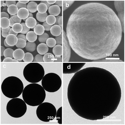
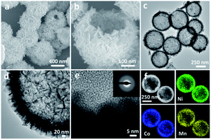
The NiCoMn-glycerate precursors were first prepared in the glycerol/isopropanol mixed solvent via a simple solvothermal approach. A diffraction peak at about 12° appeared in the XRD pattern Fig. S1,† which is a feature of metal alkoxides. As shown in Fig. 1a and b, the NiCoMn-glycerate precursors show spherical structures with about 500 nm in size. From the TEM image (Fig. 1c and d), it is evident that the NiCoMn-glycerate spheres possess solid structures and smooth surfaces, proving that metal glycerate can be easily etched in water to release metal ions.13,14 Since the NMP solvent is alkaline, NiCoMn-glycerate can be etched in NMP/H2O to convert into Ni–Co–Mn hydroxide. The corresponding XRD analysis (Fig. S2†) shows the diffraction peaks are indexed to β-Ni(OH)2 (JCPDS 14-0117). Note that the crystalline structure of Co(OH)2 and Mn(OH)2 is similar to that of Ni(OH)2.15,16 This illustrates that the replacement of some Ni2+ by Co2+ and Mn2+ does not change the β-Ni(OH)2 crystal structure in Ni–Co–Mn hydroxide.17,18 As elucidated in SEM image Fig. 2a, the achieved Ni–Co–Mn hydroxide well inherit the morphology of NiCoMn-glycerate precursors. After careful observation, it was found that Ni–Co–Mn hydroxide is composed of a hierarchical structure and assembled with crossed nanosheets. It is clear that the hollow interior of Ni–Co–Mn hydroxide can be clearly seen from an individual broken sphere (Fig. 2b). The detailed hollow interior of Ni–Co–Mn hydroxide was further observed by TEM. As shown in Fig. 2c, the structured interiors can be directly proved by the distinct contrast between the shell and inner cavities. Fig. 2d exhibits the margin of hierarchical Ni–Co–Mn hydroxide hollow spheres, it reveals that the hierarchical shell is around 50 nm in thickness, and the dark strips confirm the ultrathin feature of the assembled nanosheet subunits. As illustrated in the HRTEM image Fig. 2e, no lattice fringes can be observed. The SAED pattern (inset Fig. 2e) with broad and diffused rings is in conformity with the HRTEM result, further demonstrating the low crystalline phase of Ni–Co–Mn hydroxide. As depicted in elemental mapping images Fig. 2f, Ni, Co and Mn elements are homogeneously distributed within the hierarchical Ni–Co–Mn hydroxide hollow architectures.To illustrate the formation process of hierarchical Ni–Co–Mn hydroxide hollow architectures, the intermediates achieved at different durations were analyzed via TEM. As shown in Fig. 3a–d, the characterization results illustrate that the hierarchical Ni–Co–Mn hydroxide hollow architectures stem from NiCoMn-glycerate spheres. After reaction for 0.5 h, the surface of NiCoMn-glycerate spheres was first etched by H2O, resulting in some nanosheets closely adhering the surface of NiCoMn-glycerate spheres (Fig. 3a). After further reaction for 1.5 h, NiCoMn-glycerate spheres continue to be etched by H2O. A clear void space between the shell and core is observed, generating a yolk–shell structure (Fig. 3b). Increasing the reaction time to 2.5 h, the size of the yolk gradually becomes smaller (Fig. 3c). Extending the reaction duration to 4.0 h, the yolk is almost consumed. Finally, the NiCoMn-glycerate spheres as templates evolve into expected hierarchical Ni–Co–Mn hydroxide hollow architectures (Fig. 3d).
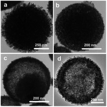 | ||
| Fig. 3 TEM images of intermediates achieved under different reaction times: (a) 0.5 h, (b) 1.5 h, (c) 2.5 h and (d) 4.0 h. | ||
To further clarify the chemical states of Ni–Co–Mn hydroxide, an XPS test was carried out and the corresponding results are plotted in Fig. S3a–c.† Both the Ni 2p and Co 2p spectra possess two sets of doublets. The Ni 2p spectrum (Fig. S3a†) exhibits two peaks at 856.3 eV (Ni 2p3/2) and 873.9 eV (Ni 2p1/2), which can be indexed to Ni2+ species.19,20 In the Co 2p spectrum (Fig. S3b†), the binding energies at 781.6 eV (Co 2p3/2) and 797.4 eV (Co 2p1/2) are assigned to Co2+ species.21,22 As shown in Fig. S3c,† the peaks at 643.1 eV and 654.4 eV correspond to Mn 2p3/2 and Mn 2p1/2.23 Based on these XPS analysis results, it is reasonable to conclude that Ni, Co and Mn elements are mostly divalent within the Ni–Co–Mn hydroxide. Therefore, NiCoMn-glycerate precursors as the template are successfully converted into Ni–Co–Mn hydroxide in the NMP/H2O mixed solvent.
Considering the Ni–Co–Mn hydroxide structural features, the nitrogen sorption test was thus performed applied to explore its specific surface area and porosity. The nitrogen sorption isotherms (Fig. 4) present classic type IV profile and H4 hysteresis loop, representing the existence of mesopore structures in the hierarchical Ni–Co–Mn hydroxide hollow architectures. Impressively, the BET surface area of Ni–Co–Mn hydroxide is determined to be 212.10 m2 g−1, and the pore volume can reach up to 0.9646 cm3 g−1. The average pore size is measured to be around 18.08 nm (inset in Fig. 4). It is traditionally considered that electrode materials with large surface area and pore volume not only facilitate the ion/electron transmission but also enlarge the electrolyte/electrode contact area. Therefore, hierarchical Ni–Co–Mn hydroxide hollow architectures as electrode materials are favorable for electrochemical energy storage.24–26
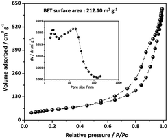 | ||
| Fig. 4 N2 sorption isotherms of hierarchical Ni–Co–Mn hydroxide hollow architectures (inset: pore size distribution curve). | ||
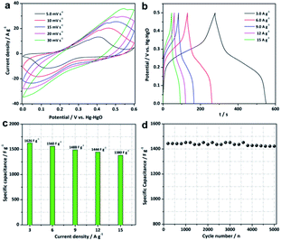
Hierarchical Ni–Co–Mn hydroxide spheres with hollow architectures, high surface area and mesopore channels are ideal alternatives for electrochemical energy storage. Thus, the electrochemical performance of Ni–Co–Mn hydroxide was evaluated in the 3.0 M KOH electrolyte using three-electrode cells. As expected, striking electrochemical performance can be achieved, as shown in Fig. 5. The cyclic voltammetry (CV) profiles from 5 to 30 mV s−1 present noticeable redox peaks (Fig. 5a), which confirm the typical pseudocapacitive features of Ni–Co–Mn hydroxide. The redox peaks are originated from the electrochemical reactions between M–O/M–O–OH (M: Ni, Co and Mn) and OH−, as represented by the following faradic redox reactions (2)–(6):11,27,28
| Ni(OH)2 + OH− ↔ NiOOH + H2O + e− | (2) |
| Co(OH)2 + OH− ↔ CoOOH + H2O + e− | (3) |
| Mn(OH)2 + OH− ↔ MnOOH + H2O + e− | (4) |
| CoOOH + OH− ↔ CoO2 + H2O + e− | (5) |
| MnOOH + OH− ↔ MnO2 + H2O + e− | (6) |
The representative all galvanostatic charge–discharge (GCD) profiles in Fig. 5b with sloped potential plateaus are in accordance with CV profiles, further proving the pseudocapacitive features of the Ni–Co–Mn hydroxide electrode. According to the GCD profiles, the specific capacitance (C, F g−1) of Ni–Co–Mn hydroxide can be achieved by the eqn (7):
 | (7) |
The specific capacitance of the Ni–Co–Mn hydroxide electrode vs. current density is plotted in Fig. 5c. Encouragingly, the hierarchical Ni–Co–Mn hydroxide hollow architecture electrode delivers specific capacitances of 1626, 1560, 1488 and 1444 F g−1 at 3.0, 6.0, 9.0 and 12 A g−1, respectively. It is remarkable that this electrode shows outstanding rate capability. Even at 15 A g−1, the specific capacitance can reach to 1380 F g−1, which is approximate 84.8% of that at 3.0 A g−1. Furthermore, the cycle stability of the Ni–Co–Mn hydroxide electrode was also evaluated. As plotted in Fig. 5d, the Ni–Co–Mn hydroxide electrode retains 98.4% of its original value after 5000 cycles at 12 A g−1. Moreover, the Ni–Co–Mn hydroxide with hierarchical hollow architectures can also be observed over 5000 cycles (Fig. S4†), further demonstrating the hierarchical Ni–Co–Mn hydroxide hollow architectures are desired electrode materials for supercapacitors. Over all, the energy storage performance of hierarchical Ni–Co–Mn hydroxide hollow architectures is superior to those of metal hydroxide electrode materials (Table S1†), such as Ni(OH)2,29,30 Co(OH)2,31 Ni–Co hydroxides/graphene,32 Ni–Co hydroxides,33 Ni–Mn hydroxides,34 Mn–Co hydroxides35 and Ni–Zn hydroxides.36
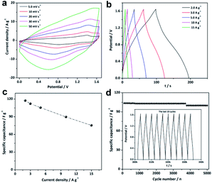
Hierarchical Ni–Co–Mn hydroxide hollow architectures as electrode materials demonstrate remarkable performance in conventional three-electrode. In this context, the Ni–Co–Mn hydroxide//AC ASC device was thus built to evaluate its practical application. As shown in Fig. 6a, the CV profiles ranging from 5.0 to 50 mV s−1 simultaneously combine the electric double-layer capacitive and pseudocapacitance features, indicating typical ASC behaviors. Moreover, all the CV profiles practically have homologous appearances, which demonstrates that the fabricated ASC device delivers notable reversibility and rate capability.37 The GCD profiles shown in Fig. 6b display a symmetrical under different current densities, representing the superior rate capability and electrochemical reversibility of the ASC device.38 The specific capacitance vs. current density profile of the ASC device are plotted in Fig. 6c. It can be seen that the ASC device demonstrates a specific capacitance of 117.45 F g−1 at 2.0 A g−1, and it still maintains 75.45 F g−1 at 15 A g−1. Around 64.2% of the specific capacitance is maintained when the current densities increase from 2.0 to 15 A g−1. Furthermore, the ASC device shows remarkably stable cycle performance. As shown in Fig. 6d, the specific capacitance decays about 3.6% over consecutive 5000 cycles at 5.0 A g−1. The last 10 GCD profiles have hardly changed (inset of Fig. 6d), further illustrating the outstanding cycles of the ASC device.
The Ragone plot (Fig. 7) shows two important parameters of the ASC device, including energy density (W h kg−1) and power density (W kg−1). The energy and power densities of the Ni–Co–Mn hydroxide//AC ASC device are calculated by the eqn (8) and (9):
 | (8) |
 | (9) |
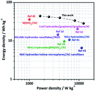 | ||
| Fig. 7 Ragone plot of the Ni–Co–Mn hydroxide//AC ASC: energy density vs. power density (other metal hydroxide assembled ASC devices are listed for comparison). | ||
As observed in Fig. 7, an energy density of 44.4 W h kg−1 is achieved at 2.0 A g−1, and the corresponding power density is 1650 W kg−1. Noticeably, the ASC device could still exhibit an energy density of 28.5 W h kg−1 when the power density is as high as 12![[thin space (1/6-em)]](https://www.rsc.org/images/entities/char_2009.gif) 374 W kg−1. In all, the electrochemical performance of the Ni–Co–Mn hydroxide//AC ASC device is better than other metal hydroxide electrode material-assembled ASC devices such as MnCo hydroxides@Ni(OH)2 (9.8 W h kg−1 to 5020.5 W kg−1),39 β-Ni(OH)2 nanosheets (36.2 W h kg−1 to 1000 W kg−1),40 α-Ni–Co hydroxide spheres (10.7 W h kg−1 to 6400 W kg−1),41 Co–Al hydroxide nanosheets (20.4 W h kg−1 to 9300 W kg−1),42 Ni–Co–Mn hydroxide nanoflakes (14.58 W h kg−1 to 3750 W kg−1) and Ni–Al hydroxide hollow spheres (6.6 W h kg−1 to 11
374 W kg−1. In all, the electrochemical performance of the Ni–Co–Mn hydroxide//AC ASC device is better than other metal hydroxide electrode material-assembled ASC devices such as MnCo hydroxides@Ni(OH)2 (9.8 W h kg−1 to 5020.5 W kg−1),39 β-Ni(OH)2 nanosheets (36.2 W h kg−1 to 1000 W kg−1),40 α-Ni–Co hydroxide spheres (10.7 W h kg−1 to 6400 W kg−1),41 Co–Al hydroxide nanosheets (20.4 W h kg−1 to 9300 W kg−1),42 Ni–Co–Mn hydroxide nanoflakes (14.58 W h kg−1 to 3750 W kg−1) and Ni–Al hydroxide hollow spheres (6.6 W h kg−1 to 11![[thin space (1/6-em)]](https://www.rsc.org/images/entities/char_2009.gif) 250 W kg−1).10,43
250 W kg−1).10,43
Hierarchical Ni–Co–Mn hydroxide hollow architectures as electrode materials exhibit desirable performance in supercapacitors. The reason can be vividly illustrated in Scheme 2: (I) hierarchical Ni–Co–Mn hydroxide with high surface area and porous not only increases its contact area with the KOH electrolyte, but also provides enough ions/electrons transmission channels;44 (II) such hollow architectures can availably endure huge volume expansion associated with continuous charge/discharge cycling, which can effectively promote the cycling stability;45 (III) the nanosheets as built subunits can shorten ion/electron diffusion distance within the electrode materials.46 Moreover, the Ni–Co–Mn hydroxide is a typical layered structure, which is favorable for ion/electron diffusion into electrode materials.47 Thus, hierarchical Ni–Co–Mn hydroxide hollow architectures show excellent performance in energy storage.
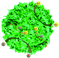 | ||
| Scheme 2 Schematic of the hierarchical Ni–Co–Mn hydroxide hollow architectures as electrode materials for high-performance supercapacitors. | ||
4. Conclusions
In summary, we present a simple etching route for the preparation of hierarchical Ni–Co–Mn hydroxide hollow architectures. The resultant hierarchical Ni–Co–Mn hydroxide hollow architectures show a large specific capacitance of 1626 F g−1 at 3.0 A g−1, remarkable rate performance and outstanding cycles performance with 98.4% capacitance retention over 5000 cycles. Furthermore, these Ni–Co–Mn hydroxide hollow architectures are employed as positive electrode to assemble an ASC device, which delivers an energy density of 44.4 W h kg−1 at a power density of 1650 W kg−1. When the power density is as high as 12![[thin space (1/6-em)]](https://www.rsc.org/images/entities/char_2009.gif) 374 W kg−1, it can retain 28.5 W h kg−1. These attractive results suggest that the hierarchical Ni–Co–Mn hydroxide hollow architectures as electrode materials have a broad application prospect in supercapacitors.
374 W kg−1, it can retain 28.5 W h kg−1. These attractive results suggest that the hierarchical Ni–Co–Mn hydroxide hollow architectures as electrode materials have a broad application prospect in supercapacitors.
Conflicts of interest
There are no conflicts to declare.Acknowledgements
This work was funded by the Henan Science and Technology (162300410003), Anyang Science and Technology, Cultivation project of Anyang Normal University (AYNUKP-2018-B17) and the Opening Research Foundations of Department of Chemistry Qingdao University of Science and Technology (QUSTHX201924).Notes and references
- L. L. Liu, Z. Q. Niu and J. Chen, Chem. Soc. Rev., 2016, 45, 4340 RSC.
- R. R. Salunkhe, Y. V. Kaneti, J. Kim, J. H. Kim and Y. Yamauchi, Acc. Chem. Res., 2016, 49, 2796 CrossRef CAS PubMed.
- J. F. Sun, C. Wu, X. F. Sun, H. Hu, C. Y. Zhi, L. R. Hou and C. Z. Yuan, J. Mater. Chem. A, 2017, 5, 9443 RSC.
- L. Liu, L. Y. Zhang, W. You and J. G. Yu, Small, 2018, 14, 1702407 CrossRef PubMed.
- X. Z. Song, F. F. Sun, Y. L. Meng, Z. W. Wang, Q. F. Su and Z. Q. Tan, New J. Chem., 2019, 43, 3601 RSC.
- Y. M. Chen, Z. Li and X. W. Lou, Angew. Chem., Int. Ed., 2015, 127, 10667 CrossRef.
- Y. Fu, J. M. Song, Y. Q. Zhu and C. B. Cao, J. Power Sources, 2014, 262, 344 CrossRef CAS.
- X. W. Hu, S. Liu, C. H. Li, J. H. Huang, J. X. Lu, P. Xu, J. Liu and X. Z. You, Nanoscale, 2016, 8, 11797 RSC.
- T. Dong, X. Zhang, M. Li, P. Wang and P. Yang, Inorg. Chem. Front., 2018, 5, 3033 RSC.
- S. R. Yang, C. Wu, J. J. Cai, Y. Zhu, H. T. Zhang, Y. Lu and K. L. Zhang, J. Mater. Chem. A, 2017, 5, 16776 RSC.
- H. C. Chen, Y. L. Qin, H. J. Cao, X. X. Song, C. H. Huang, H. B. Feng and X. S. Zhao, Energy Storage Mater, 2019, 17, 194 CrossRef.
- G. P. Xiong, G. P. Xiong, P. G. He, L. Liu, T. F. Chen and T. S. Fisher, J. Mater. Chem. A, 2015, 3, 22940 RSC.
- J. Pan, F. Wang, L. L. Zhang, S. Y. Song and H. J. Zhang, Inorg. Chem. Front., 2019, 6, 220 RSC.
- L. Yu, B. Y. Xia, X. Wang and X. W. Lou, Adv. Mater., 2016, 28, 92 CrossRef CAS PubMed.
- X. L. Wang, J. Q. Zhang, S. B. Yang, H. Y. Yan, X. D. Hong, W. Dong, Y. Liu, B. Y. Zhang and Z. Wen, Electrochim. Acta, 2019, 295, 1 CrossRef CAS.
- H. Chen, L. F. Hu, M. Chen, Y. Yan and L. M. Wu, Adv. Funct. Mater., 2014, 24, 934 CrossRef CAS.
- Q. B. Zhang, B. T. Zhao, J. X. Wang, C. Qu, H. B. Sun, K. L. Zhang and M. L. Liu, Nano Energy, 2016, 28, 475 CrossRef.
- C. H. Huang, X. X. Song, Y. L. Qin, B. H. Xu and H. C. Chen, J. Mater. Chem. A, 2018, 6, 21047 RSC.
- Y. Wang, S. L. Gai, N. Niu, F. He and P. P. Yang, J. Mater. Chem. A, 2013, 1, 9083 RSC.
- T. Wang, S. L. Zhang, X. B. Yan, M. Q. Lyu, L. Z. Wang, J. Bell and H. X. Wang, ACS Appl. Mater. Interfaces, 2017, 9, 15510 CrossRef CAS PubMed.
- G. Yilmaz, K. M. Yam, C. Zhang, H. J. Fan and G. W. Ho, Adv. Mater., 2017, 29, 1606814 CrossRef PubMed.
- Y. J. Yang, Q. X. Ma, L. Han and K. Tao, Inorg. Chem. Front., 2019, 6, 1398 RSC.
- J. H. Lin, H. N. Jia, H. Y. Liang, S. L. Chen, Y. F. Cai, J. L. Qi, C. Q. Qu, J. Cao, W. D. Fei and J. C. Feng, Chem. Eng. J., 2018, 336, 562 CrossRef CAS.
- K. K. Lee, W. S. Chin and C. H. Sow, J. Mater. Chem. A, 2014, 2, 17212 RSC.
- D. W. Li, X. X. Zhao, R. B. Yu, B. Wang, H. Wang and D. Wang, Inorg. Chem. Front., 2018, 5, 535 RSC.
- J. Y. Wang, H. J. Tang, H. Ren, R. B. Yu, J. Qi, D. Mao, H. J. Zhao and D. Wang, Adv. Sci., 2014, 1, 1400011 CrossRef PubMed.
- Y. Z. Su, K. Xiao, N. Li, Z. Q. Liu and S. Z. Qiao, J. Mater. Chem. A, 2014, 2, 13845 RSC.
- H. Chen, L. F. Hu, Y. Yan, R. C. Che, M. Chen and L. M. Wu, Adv. Energy Mater., 2013, 3, 1636 CrossRef CAS.
- Y. Wang, S. L. Gai, C. X. Li, F. He, M. L. Zhang, Y. D. Yan and P. P. Yang, Electrochim. Acta, 2013, 90, 673 CrossRef CAS.
- Q. Li, C. X. Lu, D. J. Xiao, H. F. Zhang, C. M. Chen, L. J. Xie, Y. D. Liu, S. X. Yuan, Q. Q. Kong, K. Zheng and J. Q. Yin, ChemElectroChem, 2018, 5, 1279 CrossRef CAS.
- H. B. Li, M. H. Yu, X. H. Lu, P. Liu, Y. Liang, J. Xiao, Y. X. Tong and G. W. Yang, ACS Appl. Mater. Interfaces, 2014, 6, 745 CrossRef CAS PubMed.
- Y. Bai, W. Q. Wang, R. R. Wang, J. Sun and L. Gao, J. Mater. Chem. A, 2015, 3, 12530 RSC.
- Z. Jiang, Z. P. Li, Z. H. Qin, H. Y. Sun, X. L. Jiao and D. R. Chen, Nanoscale, 2013, 5, 11770 RSC.
- X. L. Guo, X. Y. Liu, X. D. Hao, S. J. Zhu, F. Dong, Z. Q. Wen and Y. X. Zhang, Electrochim. Acta, 2016, 194, 179 CrossRef CAS.
- N. S. Wu, J. X. Lou, T. Liu, J. G. Yu and S. W. Cao, Appl. Surf. Sci., 2017, 413, 35 CrossRef CAS.
- X. B. Wang, J. J. Hu, W. D. Liu, G. Y. Wang, J. An and J. S. Lian, J. Mater. Chem. A, 2015, 3, 23333 RSC.
- A. Mohammadi, S. E. Moosavifard, A. G. Tabrizi, M. Abdi and G. Karimi, ACS Appl. Energy Mater., 2019, 2, 627 CrossRef CAS.
- L. F. Shen, L. Yu, H. B. Wu, X. Y. Yu, X. G. Zhang and X. W. Lou, Nat. Commun., 2015, 6, 6694 CrossRef CAS.
- S. D. Liu, S. C. Lee, U. Patil, I. Shackery, S. Kang, K. Zhang, J. H. Park, K. Y. Chung and S. C. Jun, J. Mater. Chem. A, 2017, 5, 1043 RSC.
- J. C. Huang, P. P. Xu, D. X. Cao, X. B. Zhou, S. N. Yang, Y. J. Li and G. L. Wang, J. Power Sources, 2014, 246, 371 CrossRef CAS.
- J. Li, M. Wei, W. Chu and N. Wang, Chem. Eng. J., 2017, 316, 277 CrossRef CAS.
- X. L. Wu, L. L. Jiang, C. L. Long, T. Wei and Z. J. Fan, Adv. Funct. Mater., 2015, 25, 1648 CrossRef CAS.
- W. C. Wang, N. Zhang, Z. Y. Shi, Z. R. Ye, Q. Y. Gao, M. J. Zhi and Z. L. Hong, Chem. Eng. J., 2018, 338, 55 CrossRef CAS.
- T. F. Yi, L. Y. Qiu, J. Mei, S. Y. Qi, P. Cui, S. H. Luo, Y. R. Zhu, Y. Xie and Y. B. He, Sci. Bull., 2020, 65, 546 CrossRef CAS.
- K. B. Xu, J. M. Yang and J. Q. Hu, J. Colloid Interface Sci., 2018, 511, 456 CrossRef CAS PubMed.
- J. M. Cao, L. Li, Y. L. Xi, J. Z. Li, X. X. Pan, D. Chen and W. Han, Sustainable Energy Fuels, 2018, 2, 1350 RSC.
- C. H. Wang, X. Zhang, Z. T. Xu, X. Z. Sun and Y. W. Ma, ACS Appl. Mater. Interfaces, 2015, 7, 19601 CrossRef CAS PubMed.
Footnote |
| † Electronic supplementary information (ESI) available. See DOI: 10.1039/d0ra10377b |
| This journal is © The Royal Society of Chemistry 2021 |


