
 Open Access Article
 This Open Access Article is licensed under a Creative Commons Attribution-Non Commercial 3.0 Unported Licence
High efficiency blue light-emitting devices based on quantum dots with core-shell structure design and surface modification
Bin Zhao *ab,
Lixuan Chenb,
Wenyong Liuc,
Longjia Wuc,
Zizhe Luc and
Weiran Cao*bc
*ab,
Lixuan Chenb,
Wenyong Liuc,
Longjia Wuc,
Zizhe Luc and
Weiran Cao*bc
aSchool of Electronic and Information Engineering, South China University of Technology, Tianhe District, Guangzhou 510641, China. E-mail: csotzhaobin@tcl.com
bShenzhen China Star Optoelectronics Semiconductor Display Technology Co., LTd, Guangming District, Shenzhen 518132, China. E-mail: caowr@tcl.com
cTCL Research, 1001 Zhongshan Park Road, Nanshan District, Shenzhen 518067, China
First published on 14th April 2021
Abstract
Blue quantum dot (QD) light emitting diode (QLED) developments are far lagging behind the red and green ones as it becomes difficult to balance charge injection and photo stability than the latter. Here, we introduced a combination of a low band energy shell with better surfactants, which largely meet both abovementioned requirements. Our simulation pinpoints that it is the exposed Se on the QD surface, which causes non-radiative relaxations. By adding tributyl phosphine (TBP), which is a good ligand to Se, we recover photoluminescence quantum yield (PLQY) from less than 8.0% up to above 85.0%. The corresponding external quantum efficiency (EQE) of QLEDs increases from 3.1% to 10.1%. This demonstrates that the low bandgap shell with effective surfactant passivation is a promising strategy to enhance QLED performance.
Introduction
Electrically driven light emission of quantum dot light emitting diodes (QLEDs) has attracted considerable interest in recent years due to its promising potentials as a novel display technology.1–3 It benefits from the merits of foldability, wide color gamut and low manufacturing cost due to its flexible structure, narrow full width at half maximum of quantum dots (QDs), and ink-jet printing process, respectively.6 Therefore, QLEDs foresee a bright future among the competitive innovative display technologies.By combining efforts of QD synthetic optimizations and device fabrication improvements during last two decades, the QLED performance gradually enhanced.1,7,8 During the last few years, with increasing involvement from major display manufacturers, QLED embraced an accelerated development, largely for the red and green ones.2,3 Blue QLEDs, on the other hand, have far lagged behind mainly due to the synergetic effects of the poor charge injection balance and high applied voltage.9 While we are preparing this manuscript, Samsung reports ZnSexTe1−x-based blue quantum dots with the assistance of the ZnCl2 surface treatment that achieved high external quantum efficiency (EQE) and extensive operational stability.10 ZnCl2 is used to passivate the anionic dangling bonds on the surface in order to mitigate surface non-radiative traps and also facilitate the charge injection.
With the state-of-art device structure using ZnO nanoparticles as electron transfer layer (ETL) and TFB as hole transfer layer (HTL), energy levels for both electron and hole injections are fixed. In order to balance the charge transfer, one way is to insert a charge block layer. Although it can effectively improve device EQE and operation stability, an additional thin electron blocking layer suffers from reproducibility issues due to the poor control of the film uniformity and thickness.1 Another way is to manipulate the energy levels of QD core shell structures so as to accommodate the alignment offsets from ETL and HTL. Cao et al. utilized a narrow bandgap ZnSe shell to effectively mitigate the hole injection barrier of red QDs.3 With this approach, it reports an EQE of 15.1% and the T95 device operation lifetime of more than 2300 h with an initial brightness of 1000 cd m−2, the longest up to date. Besides red, ZnSe shell has also been successfully utilized in previous studies to facilitate carrier injections for blue QLEDs, further demonstrating its generality.4,5 Inspired by this shell design, here, we tackle the blue QLED charge problem using a similar approach with necessary surface modifications in order to preserve the photostability.
In previous studies, very often ZnS is used as the outer shell to strongly confine excitonic wavefunctions in blue cores aiming at maintaining high photo stability.11 However, the large bandgap of the shell impedes both electron and hole from passing into the core, hence compromising device performance. On the other hand, the tentative use of ZnSe as the shell favors the charge injection, but severely deteriorates QD photoluminescence due to the weak confinement. One way to solve this issue is to eliminate surface traps with selectively picked surfactants.6
Here, we demonstrate the use of both oleic acid (OA) and alkyl phosphine to passivate cations and anions on the surface, respectively. Blue-colored Cd0.1Zn0.9Se/ZnSe core shells can not only preserve high photoluminescence but also achieve excellent EQE. The pristine OA surfactants mainly passivate dangling bonds on zinc. By addition of alkyl phosphine post synthesis, it can effectively bind on the hole trap-intending selenium and therefore improve photoluminescence from less than 8.0% up to above 85.0%. Furthermore, the corresponding EQE of electrical-excited device increased from 3.1% up to 10.1%. It provides a new insight that the low bandgap shell with pinpointing surfactant passivation is an effective strategy to enhance the performance QLED.
Results and discussions
The Cd0.1Zn0.9Se/ZnSe core shells are synthesized following a three-step process. First, ZnSe nuclei is formed by the swift injection of Se into a redundant Zn ion solution, then Cd ions are continuously added to form the Cd0.1Zn0.9Se/ZnSe core before it is completed with the further slow addition of Se to form a ZnSe shell. TEM shows the size of QDs is approximately 6–7 nm with roughly spherical morphology and excellent crystallinity (Fig. 1b). Uniformly alloyed core and smooth interface between the core and shell are guaranteed using both high annealing temperature and sufficiently long cooking duration (Fig. 1a left). Both theoretical12 and experimental13 evidence demonstrate that smoothly connected energy levels in QDs can both mitigate Auger recombination and facilitate charge injections (Fig. 1a right). Our synthetic strategy is designed to exclusively accommodate this requirement. The protective ZnS layer is intentionally eliminated in this case to ease both electron and hole injections.3 Unsurprisingly, as a result of it, the QDs suffer from decrease in the photoluminescence quantum yield (PLQY) after purification (Fig. 1c blue curve and 1d blue spot). After standard three time washings, the PLQY drops to below 8.0%. This can be elucidated by the unavoidable wavefunction extensions to the surface. Our calculation shows that the dangling bonds of Se on the QD surface tend to be hole traps, which in turn create non-radiative relaxation channels. The as-synthesized QDs exhibit decent photoluminescence due to the usage of both oleic acid and trioctyl phosphine (TOP) during synthesis, with former binding to Zn ions and latter to Se. However, after purification, the free ligands were cleaned away as well as the weakly bound surfactants such as TOP, leaving Se exposed. To solve this issue, we reintroduced phosphine ligands during the post purification process to enhance PLQY. Phosphines including TOP and tributyl phosphine (TBP) are good ligands to Se, which are routinely used as precursors in the QD synthesis.14 By adding a trace amount of phosphine into the QD solution, the PLQY quickly bounced back to 64.0% and with further optimization of the phosphine amount, it can reach above 85.0% (Fig. 1c red curve and 1d red spot). Also, this little amount of ligand can boost photoluminescence but not enough to significantly affect the electrical property of the following light emitting devices, therefore perfectly solving the trap problem. The emission peak is at 465.8 nm with the full width at half maximum (FWHM) of ∼21 nm, which is the same as that of the pristine QDs.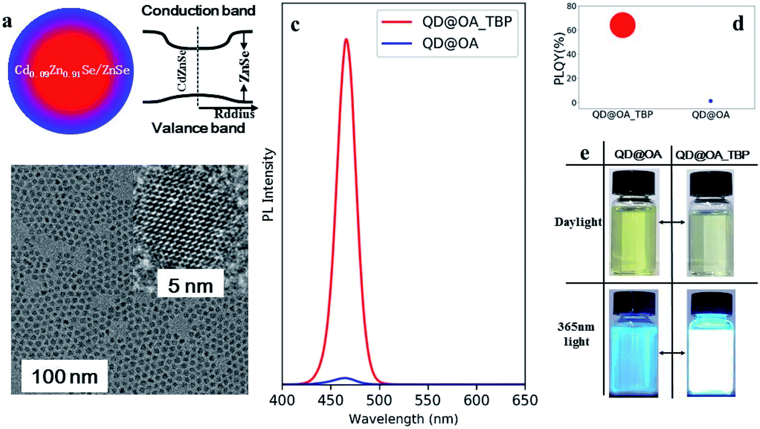 | ||
| Fig. 1 Colloidal quantum dots. (a) The schemes of Cd0.1Zn0.9Se/ZnSe core shells and its energy levels. (b) TEM images with HRTEM in the inset, the QD are roughly spherical and size is around 6–7 nm. (c) Luminescence peaks comparison between oleic acid (OA) and tributyl phosphine (TBP) (red curve) and OA only (blue curve). (d) The PLQY of OA_TBP and OA only capped QDs, the sizes of the spots are proportionate to their PLQY values. (e) The images of QD@OA and QD@OA_TBP under daylight and blue light excitations. | ||
In a typical synthesis, Zn(Ac)2 (12 mmol), oleic acid (20 ml) and ODE (10 ml) are filled into a 50 ml three-necked round bottom flask. The mixture is stirred and heated to 100 °C before purging with N2 for around 30 min to dissolve the salt and remove acetic acid. After it totally dissolves, the solution becomes either clear or slightly yellowish in color. Then, after the solution is heated up to 300 °C, the TOPSe solution (3.6 ml with a concentration of 0.67 M) is swiftly injected. 40 s later, Cd(OA)2 (1.5 ml with a concentration of 0.2 M) is continuously injected at a rate of 75 μl min−1 for 20 min. After the addition, the solution is heated for another 40 min for annealing. It is then followed by the slow addition of TOPSe (1.34 ml with a concentration of 0.67 M) at a rate of 45 μl min−1 for 30 min. After the addition, the solution is naturally cooled to room temperature and subjected to washing process.
Due to the high surface to volume ratio of quantum dots, the trap states caused by the dangling bonds of surface atoms cannot be ignored. These mid-gap states can act as non-radiative recombination centers.15,16 To demonstrate from a theoretical perspective, we performed simulations via density functional theory (DFT). The surface of quantum dots was simulated to understand the trap states caused by the dangling bonds of the surface atoms. According to our quantum dot structure, the (100) wurtzite ZnSe is used as the surface model. The density of states (DOS) of passivated and un-passivated surfaces is compared. As shown in Fig. 2, without passivation, a significant amount of defect states are presented within the bandgap. These defect states contribute to the Auger recombination, thus decreasing the quantum efficiency. After passivating the Zn and Se dangling bonds on the surface, 84% of the defect states in the mid-gap disappear as shown by the red line in Fig. 2. Therefore, choosing the appropriate ligand to passivate the QD surface is critical.
 | ||
| Fig. 2 The DOS of the (100) ZnSe surface with and without ligand passivation. The figure is reprinted from ref. 6. | ||
In previous studies, different ligands have been used to passivate the surface of QDs in order to achieve a better device efficiency.6,17–19 In our case, we demonstrate that the OA and alkyl phosphine are complementary with each other to bind both Zn and Se on the QD surface. In particular, alkyl phosphine forms a coordination bond with Se and is regularly used as the Se precursor for the metal chalcogenide QD synthesis. To demonstrate this claim, phosphine ligands are introduced into the purified blue QD solution, and the PLQY of the colloidal quantum dots before and after adding the ligands is investigated. As shown in Fig. 3a, as the phosphine ligand concentration increases, the PLQY of the Cd0.1Zn0.9Se/ZnSe@OA blue QDs is significantly improved due to the effective passivation of phosphine ligands on under-coordinated Se anion sites,20,21 corresponding well with the simulation results above, showing the major trap states of the Cd0.1Zn0.9Se/ZnSe@OA blue QDs are the Se anion defect sites. Moreover, phosphine ligands with the alkyl chain of different length affect the PLQY recovery. With TOP that has three octyl branches, the PLQY of the QDs rise to ∼74% at the optimal TOP ligand's quantity, while TBP that has three butyl branches increase the PLQY of the blue QDs to almost 90% under the same condition. The smaller molecular size of the TBP ligands and the corresponding higher surface ligand coverage on the blue QDs is the reason to cause this difference and lead to a better surface passivation. Moreover, other types of ligands with different function groups, such as pristine oleic acid (OA) and octanethiol (OT), had also been tested with the Cd0.1Zn0.9Se/ZnSe blue QDs, and the optimal PLQY of the blue QDs after surface passivation with each type of ligands has been summarized in Fig. 3b. It can be seen that the surface ligands with carboxylate or thiol functional groups do not recover the PLQY of the Cd0.1Zn0.9Se/ZnSe@OA blue QDs as effective as alkyl phosphines. It is well known that the carboxylate and thiol ligands prefer surface cation sites passivation, but only have limited effect on anions.22,23 Therefore, the surface ligands with the carboxylate group or thiol groups do not effectively passivate with the Se defect sites, and the major trap states of the Cd0.1Zn0.9Se/ZnSe@OA blue QDs as shown in the simulation results, resulting in an unsatisfied PLQY recovery of the blue QDs.
 | ||
| Fig. 3 The effect of phosphine ligands on PLQY of the Cd0.1Zn0.9Se/ZnSe@OA blue QDs. (a) Cd0.1Zn0.9Se/ZnSe@OA blue QD PLQY after adding TOP or TBP with different concentrations of phosphine ligands, respectively. The inset photograph taken under illumination at 365 nm, from left to right: before and after adding TBP ligands into the purified blue QDs. (b) The optimal photoluminescence quantum yield of the Cd0.1Zn0.9Se/ZnSe@OA blue QDs after surface passivation with different coordination groups of surface ligands. | ||
To illustrate the influence of ligands on the device performance,23 the blue QLED devices (Cd0.1Zn0.9Se/ZnSe@OA and Cd0.1Zn0.9Se/ZnSe@OA_TBP devices) were prepared. The QLED device configuration is as follows: glass/ITO (50 nm)/poly(3,4-ethylenedioxythiophene) polystyrene sulfonate (PEDOT: PSS 35 nm)/poly(9,9-dioctylfluorene)-co-(N-(4-butylphenyl)diphenylamine) (TFB 25 nm)/QDs (20 nm)/ZnO (35 nm)/Al (100 nm) (Fig. 4a). For the organic–inorganic hybrid QLED devices, all functional layers were spin-coated except the anode and cathode.24 A glass substrate with patterned 50 nm indium tin oxide (ITO, sheet resistance is about 50 Ω □−1) anode were cleaned by ultrasonic treatment in a tergitol/deionized (DI)-water solution, DI-water, and isopropanol, respectively, followed by treatment with under ultraviolet (UV)–ozone for 15 min. A PEDOT: PSS layer as the hole injection layer (HIL) was spin-coated onto the pre-cleaned ITO substrates at 5000 rpm and then baked at 150 °C under air condition. TFB dispersed in chlorobenzene was spin-coated at 2000 rpm and annealed at 150 °C under a N2 atmosphere. After that, one QD and ZnO nanoparticle layer were sequentially deposited from the octane and ethanol solution in the glove-box, respectively, via the spin-coating method and annealed in the same environment at 80 °C. The Al cathode was thermally deposited in a vacuum chamber under the chamber pressure less than 10−6 torr through a shadow mask to obtain active areas of 2 × 2 mm2. Finally, the blue QLED devices were encapsulated using a UV-epoxy resin and a cover glass in the N2 atmosphere. A digital source meter (Keithley 2400) was used to operate the devices and measure the J–V characteristics. Electroluminescence spectra were recorded using an Ocean Optics USB 2000+ spectrometer. Light intensities of devices were measured with a Keithley 6485 Picoammeter together with a calibrated silicon detector (Edmund). EQEs were calculated from the luminance, current density, and EL spectra with the assumption of the Lambertian emission pattern of all devices.25,26
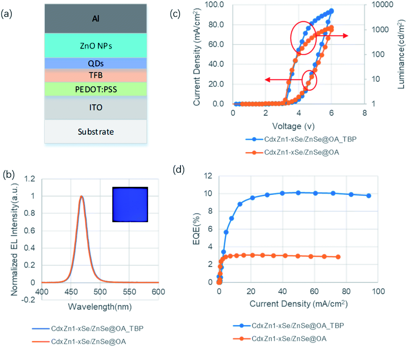 | ||
| Fig. 4 Device structure and performance of the blue device: (a) bottom emission device structure, (b) normalized EL spectrum of QD@OA and QD@OA_TBP, respectively, (c) he current density and luminance of QLEDs, and (d) EQE vs. current density. | ||
The normalized electroluminescence (EL) spectra of the devices based on Cd0.1Zn0.9Se/ZnSe@OA and Cd0.1Zn0.9Se/ZnSe@OA_TBP are shown in Fig. 4b. To simplify the nomination, hereafter the former is named as QD@OA and the latter is QD@OA_TBP. Both QLED devices exhibited the same narrow EL emission at a peak wavelength of 469 nm with a FWHM of 21 nm. While FWHM is preserved, the EL peak position redshifted 3.2 nm compared to that in the solution. This is mainly due to the increasing exciton wavefunction communications of QD after they are closed packed on the solid film. Pure blue emission is observed in the inserted photograph of QLED fabricated using QD@OA_TBP. Fig. 4c shows the current density (J)–voltage (V)–luminance (L) characteristics of QD@OA and QD@OA_TBP devices. Both devices show the same turn-on voltage (VT) of 3.2 V defined as the required operation voltage for achieving the luminance of 1 cd m−2. The J–V–L characteristics are not that much different at a low J region (<4 V). However, the luminance of the QD@OA_TBP device increases rapidly at the >4 V region. The QD@OA_TBP device shows about four times higher luminance (2322 cd m−2) than that of the QD@OA device (590 cd m−2). The external quantum efficiency (ηEQE) of the QD@OA and QD@OA_TBP devices are exhibited in Fig. 4d. The latter shows the maximum ηEQE value of 10.1%, which is about 3.3-fold higher than that of the former device. Similarly, high EQE was also reported in the literature via functional layer modifications.4,5 To note, all the device fabrication processes are kept the same, and the only difference is to add trace amounts of TBP into the QD solution for the QD@OA_TBP device. Compared to the OA only case which favours Zn, TBP complements the passivation of Se, which further mitigates the non-radiative relaxation centers. Besides, in contrast to TOP, which has large steric hindrance and high boiling point, the TBP molecule is small and volatile, which indicates a more effective passivation of QD and easy removal for the excessive ones during the QD film preparation process, both of which are beneficial for the device characteristic improvement.
Conclusions
In summary, the present study demonstrates the blue QLEDs with high EQE and low threshold voltage. This is achieved through the synergistic effects of tuning the energy level of QD to match adjacent functional layers and effective ligand passivation to largely eliminate non-radiative traps on the surface. In particular, we introduce TBP to QD as additional surfactants, which complement the original OA to bind on the dangling bonds of Se on the surface. Compared to other long chain alkyl phosphines, TBP has the merits of low steric hindrance and high volatility, which favor more passivation to surface Se sites and ease for nonbinding ones to remove during device fabrication. TBP-modified QDs witness the PLQY recovery from less than 8.0% up to above 85.0%, and compared to the pristine QD@OA, the EQE of QD@OA_TBP devices has 3.3-fold enhancement from 3.1% to 10.1% with a threshold voltage as low as 3.2 V. This demonstrates that a low bandgap shell design with effective surfactant passivation is a promising strategy to enhance the performance of QLED.Experimental details
Procedures for the blue QD preparations
Cd(OA)2 (0.2 M) is prepared by reacting CdO 1.0 mmol with OA 1 ml and ODE 4.0 ml at 250 °C. The solution is bubbled with N2 at 80 °C for 20 min before cooling down.
(1) Cd0.1Zn0.9Se core preparation. Zn(ac)2 (5.0 mmol), OA (5 ml) and ODE (20 ml) are added into a 100 ml round bottom three-neck flask. The mixture is bubbled with N2 at 130 °C for 1 h before heating up to 310 °C. When the temperature is stable, the TOPSe (0.8 ml) and DPP (0.3 ml) mixture is swiftly injected into the solution, triggering the burst of ZnSe nuclei. The temperature drops down to 300 °C and the solution continues to cook for 50 s before Cd(OA)2 (0.4 ml) is rapidly injected into the solution. The Zn0.9Cd0.1Se core is furthermore cooked for 1 h at 300 °C.
(2) Cd0.1Zn0.9Se/ZnSe shell coating. With the hot solution in section 1 at 300 °C, TOPSe (0.5 ml) is slowly added for 13 min 20 s at constant rate using a syringe pump. With the excess Zn(OA)2 in the solution, the ZnSe shell is gradually formed during this process. Then, the solution is cooled down to room temperature and subjected to cleaning by going through 3 times of precipitation with ethanol and dissolution with octane cycle. Then, the QD is stored in an octane solution for the following use.
QD solution PLQY measurement
Blue QD solution PLQY is measured via the integrated sphere method using Edinburgh Instruments FS5 SC-30. The instrument includes an FS5 fluorescence plus SC-30 integrated sphere module. The procedures to perform the measurements are following:The instrument is first to be turned on and warmed up for 30 min before the operation. Next step is to set the excitation and emission wavelengths both at 465 nm, and tune the both bandwidths to make sure signal rate reaching 1 × 10⁶ cps. The third is to set the emission range from 400 up to 650 nm with the step of 0.2 nm, dwell time of 0.2 s and the number of scan of 1. Also, the excitation wavelength was set at 360 nm. For the fourth step, the cuvette with the octane solvent was put into the center of the integrated sphere and the spectrum was recorded as the control. Then, the cuvette with the octane solution of QD with absorptance at the excitation wavelength around between 0.1 and 0.15 is to replace the previous control cuvette and perform the same scan. By subtracting the later with former, PLQY can be obtained.
Device characterizations
The device testing system is composed of a high-precision digital source meter, high-performance optical spectrometer and optical fiber (inner diameter 50 μm), device testing probe and data acquisition system. The J–V characteristics of quantum dot devices were measured under ambient condition using a digital source meter (Keithley 2400) measuring the sweeping voltages and currents. The maximum voltage was set up 6 V and the voltage variable step was set up 0.2 V during measuring. Simultaneously, light intensities were measured on a Keithley 6485 Picoammeter together and a calibrated silicon detector (Edmund). Luminance was calibrated using a photometer (Spectra Scan PR655) with the assumption of the Lambertian emission pattern of all devices. Electroluminescence spectra were recorded using a high performance Ocean Optics USB 2000+ spectrometer.Conflicts of interest
There are no conflicts to declare.References
- X. Dai, Z. Zhang, Y. Jin, Y. Niu, H. Cao, X. Liang, L. Chen, J. Wang and X. Peng, Solution-processed, high-performance light-emitting diodes based on quantum dots, Nature, 2014, 515, 96–99 CrossRef CAS PubMed.
- W. Yu-Ho, O. Cho, T. Kim, D. Chung, T. Kim, H. Chung, H. Jang, J. Lee, D. Kim and E. Jang, Highly efficient and stable InP/ZnSe/ZnS quantum dot light-emitting diodes, Nature, 2019, 575, 634–638 CrossRef PubMed.
- W. Cao, C. Xiang, Y. Yang, Q. Chen, L. Chen, X. Yang and L. Qian, Highly stable QLEDs with improved hole injection via quantum dot structure tailoring, Nat. Commun., 2018, 9, 2608 CrossRef PubMed.
- L. Wang, T. Chen, Q. Lin, H. Shen, A. Wang, H. Wang, C. Li and L. Li, Org. Electron., 2016, 37, 280 CrossRef.
- T. Zhang, X. Zhang, P. Yang, J. Bai, C. Chang, X. Jin, F. Zhao, Y. Huang and F. Li, J. Nanomater., 2019, 9257018 CAS.
- C. Xiang, L. Wu, Z. Lu, M. Li, Y. Wen, Y. Yang, W. Liu, T. Zhang, W. Cao, S. Tsang, B. Shan, X. Yan and L. Qian, High efficiency and stability of ink-jet printed quantum dot light emitting diodes, Nat. Commun., 2020, 11, 1646 CrossRef PubMed.
- V. Colvin, M. Schlamp and A. Alivisatos, Light-Emitting-Diodes Made from Cadmium Selenide Nanocrystals and a Semiconducting Polymer, Nature, 1994, 370, 354–357 CrossRef CAS.
- Y. Shirasaki, G. Supran, M. Bawendi and V. Bulovic, Emergence of Colloidal Quantum-Dot Light-Emitting Technologies, Nat. Photonics, 2013, 7, 13–23 CrossRef CAS.
- D. Li, T. Zhang, C. Chang, X. Jin, Z. Huang, B. Xu and Q. Li, Blue quantum dot light-emitting diodes with high luminance by improving the charge transfer balance, Chem. Commun., 2019, 1–4 Search PubMed.
- T. Kim, K. Kim, S. Kim, S. Choi, H. Jang, H. Seo, J. Lee, D. Chung and E. Jang, Efficient and stable blue quantum dot light-emitting diode, Nature, 2020, 586, 385 CrossRef CAS PubMed.
- H. Shen, W. Cao, N. T. Shewmon, C. Yang, S. Li and J. Xue, High-Efficiency, Low Turn-on Voltage Blue-Violet Quantum-Dot-Based Light-Emitting Diodes, Nano Lett., 2015, 15, 1211–1216 CrossRef CAS PubMed.
- R. Vaxenburg, A. Rodina, E. Lifshitz and L. Efros, Biexciton Auger recombination in CdSe/CdS core/shell semiconductor nanocrystals, Nano Lett., 2016, 16, 2503–2511 CrossRef CAS PubMed.
- J. Lim, Y. Park, K. Wu, H. Yun and V. Klimov, Droop-Free Colloidal Quantum Dot Light Emitting Diodes, Nano Lett., 2018, 18, 6645–6653 CrossRef CAS PubMed.
- C. B. Murray, D. J. Norris and M. G. Bawendi, Synthesis and characterization of nearly monodisperse CdE (E = sulfur, selenium, tellurium) semiconductor nanocrystallites, J. Am. Chem. Soc., 1993, 115(19), 8706–8715 CrossRef CAS.
- J. Tang, et al., Colloidal-quantum-dot photovoltaics using atomic-ligand passivation, Nat. Mater., 2011, 10, 765–771 CrossRef CAS PubMed.
- A. H. Ip, et al., Hybrid passivated colloidal quantum dot solids, Nat. Nanotechnol., 2012, 7, 577–582 CrossRef CAS PubMed.
- B. H. Kang, et al., Efficient exciton generation in atomic passivated CdSe/ZnS quantum dots light-emitting devices, Sci. Rep., 2016, 6, 34659 CrossRef CAS PubMed.
- X. Li, et al., Bright colloidal quantum dot light-emitting diodes enabled by efficient chlorination, Nat. Photonics, 2018, 12, 159–164 CrossRef CAS.
- H. Shen, et al., High-efficiency, low turn-on voltage blue-violet quantum-dot-based light-emitting diodes, Nano Lett., 2015, 15, 1211–1216 CrossRef CAS PubMed.
- M. A. Boles, D. Ling, T. Hyeon and D. V. Talapin, The surface science of nanocrystals, Nat. Mater., 2016, 15, 141–153 CrossRef CAS PubMed.
- M. Green, The nature of quantum dot capping layers, J. Mater. Chem., 2010, 20, 5797–5809 RSC.
- J. Owen, The coordination chemistry of nanocrystal surfaces, Science, 2015, 347, 615–616 CrossRef CAS PubMed.
- C. D. Pu, X. L. Dai, Y. Z. Jin and X. G. Peng, Electrochemically-stable ligands bridge the photoluminescence-electroluminescence gap of quantum dots, Nat. Commun., 2020, 11, 937–946 CrossRef CAS PubMed.
- C. Ippen, T. Greco, C. J. Han and A. Wedel, ZnSe/ZnS quantum dots as emitting material in blue QD-LEDs with narrow emission peak and wavelength tunability, Org. Electron., 2014, 15(1), 126–131 CrossRef CAS.
- S. R. Forrest, D. D. C. Bradley and M. E. Thompson, Measuring the efficiency of organic light-emitting devices, Adv. Mater., 2003, 15, 1043–1048 CrossRef CAS.
- S. Okamoto, K. Tanaka, Y. Izumi, H. Adachi, T. Yamaji and T. Suzuki, Simple Measurement of Quantum Efficiency in Organic Electroluminescent Devices, Jpn. J. Appl. Phys., 2001, 2(40), L783–L784 CrossRef.
| This journal is © The Royal Society of Chemistry 2021 |