
 Open Access Article
 This Open Access Article is licensed under a Creative Commons Attribution-Non Commercial 3.0 Unported Licence
Enhancing the efficiency of the hydrogen evolution reaction utilising Fe3P bulk modified screen-printed electrodes via the application of a magnetic field†
Jack. P. Hughesab,
Samuel Rowley-Neale *ab and
Craig Banks*ab
*ab and
Craig Banks*ab
aFaculty of Science and Engineering, Manchester Metropolitan University, Chester Street, Manchester M1 5GD, UK. E-mail: c.banks@mmu.ac.uk; Fax: +44 (0)1612476831; Tel: +44 (0)1612471196
bManchester Fuel Cell Innovation Centre, Manchester Metropolitan University, Chester Street, Manchester M1 5GD, UK. E-mail: S.Rowley-Neale@mmu.ac.uk
First published on 18th February 2021
Abstract
We report the fabrication and optimisation of Fe3P bulk modified screen-printed electrochemical platforms (SPEs) for the hydrogen evolution reaction (HER) within acidic media. We optimise the achievable current density towards the HER of the Fe3P SPEs by utilising ball-milled Fe3P variants and increasing the mass percentage of Fe3P incorporated into the SPEs. Additionally, the synergy of the application of a variable weak (constant) external magnetic field (330 mT to 40 mT) beneficially augments the current density output by 56%. This paper not only highlights the benefits of physical catalyst optimisation but also demonstrates a methodology to further enhance the cathodic efficiency of the HER with the facile application of a weak (constant) magnetic field.
Introduction
Electricity produced from renewable sources such as wind turbines, solar PV and tidal power can be converted to chemical energy in the form of green hydrogen gas.1,2 The energy density of green hydrogen gas (140 MJ kg−1) is greater than fossil fuels such as: coal (24 MJ kg−1), natural gas (55 MJ kg−1) and petrol (44 MJ kg−1) making it a promising alternative energy source.3 Green hydrogen is generated within an electrolyser and has no direct carbon by-products, whereas ‘grey’ hydrogen is produced in processes such as natural gas reformation and coal or biomass gasification where the by-products are CO2 and CO.4,5 The cathodic reaction within a proton exchange membrane (PEM) electrolyser is the hydrogen evolution reaction (HER; 2H+ + 2e− → H2), where protons are electrochemically reduced to hydrogen gas formed at the surface of a suitable cathode.6,7Platinum (Pt) based cathodic materials are commonly required within commercial electrolysers to carry out efficient water splitting, given that they are highly active and stable catalysts for electrolytic applications.8 However, the application of Pt based materials within electrolysers is limited by their high cost and low abundance,9–11 therefore research is directed towards discovering active and stable non-precious metals (NPM) cathodic catalysts.12–15 Transition metal phosphides (TMPs) are regarded as promising cathodic catalysts, composed of active transition metals such as Ni,16–18 Co19–21 and Fe22–24 which are stabilized when alloyed with phosphides.16 An interesting study by Schipper et al.25 reported on the effects of phase transition of FeP, Fe2P and Fe3P films electrodeposited on the surface of fluorine doped tin oxide (FTO). An increase in ferric content within the phases led to increased activity towards the HER, resulting in low HER overpotentials of 116, 83, 49 and 8 mV (vs. RHE) for FeP, Fe2P, Fe3P and Pt, respectively. The films exhibited high achievable current densities, in excess of −100 mA cm−2 and promising stability within acidic conditions during chronoamperometric measurements at −120 mV (vs. RHE) for 20 hours. Iron phosphides contain exposed stepped surfaces of 3-fold Fe and Fe–Fe bridge sites that are thought to exhibit affinity for H+ ions.26 FeP is mainly composed of Fe–P sites (which result in weak adsorption), where up to six P atoms are covalently bonded to an FeIII centre in an orthorhombic crystal system.27 Fe2P consists of a combination of tetrahedral FeI and pyramidal FeII sites, each site arranged in a hexagonal crystal system where there are a maximum of four Fe–P interactions per Fe atom.28,29 Within the iron phosphides, Fe3P contains the weakest covalent bonds, but the strongest ionic interactions, metallicity and contains the largest number of Fe–Fe interactions.30 This is a result of Fe3P consisting of FeI centres arranged in a tetragonal crystal system where the increase in ferric content leads to a maximum of three Fe–P covalent bonds and an increase in favourable Fe–Fe interactions.31 Clearly, Fe3P is a very interesting material to study towards the HER.
In addition to material optimisation, as reported above for iron phosphides, another interesting approach to increase the cathodic efficiency of electrolysis is by using an external magnetic field.32,33 This is due to Lorentz force induced convection via magnetohydrodynamic (MHD) and micro-MHD effects,34 in which the former results in diffusion layer thinning, improving the mass and charge transfer of H+ and e− ions. In the latter, a perpendicular magnetic field can induce flow patterns at very small scales, close to the electrode surface (i.e. within the diffusion layer), which is impossible through mechanical agitation and regulates bubble removal at the electrode surface in the clockwise or anticlockwise direction, leading to the reduction of ohmic loss, and the increased availability of active sites.34–37 Elias et al.32 have studied the effect of a magnetic field on the HER by applying magnetic flux densities (B) between 0.1–0.4 T to enhance HER efficiency in Ni–W alloy electrodes. It was found that the HER onset potential of −1.35 V (vs. SCE) for the Ni–W electrode when B = 0, was reduced to −1.01 V (vs. SCE) when B = 0.4 T. Additionally, there was an increase in current density from −0.70 to ca. −0.82 A cm−2 at B = 0.1 T and B = 0.4 T, respectively. Ferromagnetic materials such as Fe, Ni and Co38 are highly affected by an applied magnetic field and amplify the Lorentz effect, whereas materials such as Pt (paramagnetic) and graphite (diamagnetic) are largely unaffected.39 This is due to the Zeeman effect where the distortion of electron orbitals within magnetic materials in the presence of a magnetic field leads to decreased energy barriers and enhanced electron transfer.40 Fe3P is a robust ferromagnetic material, hence exhibits magnetic properties that are required to enhance HER efficiency within water electrolysis.41
The assessment criteria of a NPM cathodic catalysts' suitability for use in PEM electrolysis is dependent upon a number of critical factors; proficient HER catalysis, high achievable current density and stability in acidic media. Another important factor, often forgotten, is the ability to translate research outputs to industry – mass-printable screen-printed electrodes can help this transition. Consequently, in this paper, we report the incorporation of Fe3P variants into SPEs and optimise their performance as HER catalysis in acidic conditions; the effect of applying a weak magnetic field is also explored and found to provide beneficial outputs to the HER.
Experimental section
Chemicals
All chemicals used were of analytical grade from Sigma Aldrich and were without need of any further purification. The Fe3P powder (product code: 691593; Sigma Aldrich, UK) and Fe2P powder (product code: 691658; Sigma Aldrich, UK) utilised were of 99.5% purity (trace metals basis, −40 mesh avg. part. size). These are referred to in the text with a subscript “raw” to indicate that they were used, raw, without any treatment.The Fe3P powder was wet ball milled in a Retsch PM 100 planetary ball mill over the following time intervals: 5, 10, 20 and 50 h in a 50 mL zirconium oxide (ZrO2) grinding jar (Retsch, Germany). Ball milling was carried out with 2 mm yttrium stabilized zirconia beads (Retsch, Germany) at 150 rpm, where 2 g Fe3P was placed in 30 mL methanol to form a milling slurry. The 2 mm diameter of the zirconia beads and milling speed have been previously shown to result in the finest powder dispersion.42 Electrochemical measurements were performed in 0.5 M H2SO4, which was of the highest possible purity from Sigma Aldrich (99.999%, double distilled for trace metal analysis).
Electrochemical measurements
The electrolyte (0.5 M H2SO4) was made using deionized water (resistivity 18.2 MΩ cm), which was degassed with high purity nitrogen before electrochemical measurements. It is common within research conducting HER experiments to remove any trace of oxygen, to prevent the onset of the competing ORR. An Autolab Compact™ (Switzerland) potentiostat was used to carry out electrochemical measurements. A three-electrode system was used to take measurements with modified and bare graphitic screen printed electrodes (SPEs) with a working area diameter of 3.1 mm used as working electrodes, with a carbon counter and a saturated calomel electrode (SCE) reference. The neodymium ring magnets (30 × 10 × 10 I.D. mm, magnetic field strength: 0.44 T, First4Magnets, product code: F3010DM-1) used for electrochemical measurements were placed in incremental distances from the electrode surface, highlighted in the ESI Table T1.† The screen-printing process used to produce the Fe2P and Fe3P SPEs utilised within this study is explained within the ESI† and is also described in more depth in previous studies.11,43–45 Herein, the potential is referenced to the reversible hydrogen electrode (RHE) utilising the following equation, as is common within the literature:46–48 ERHE = ESCE + 0.059pH + 0.242 V (at 25 °C).Physicochemical characterisation of the raw and ball milled Fe3P powders
It was important to assess the particle size and distribution of the raw Fe3P powder using Scanning Electron Microscopy (SEM) and Energy Dispersive X-ray (EDX) elemental mapping to compare against the (wet) ball-milled variants. In the ESI, Fig. S1(A1)† shows an SEM image of the raw Fe3P powder, where the average particle size is ca. 400 μm. SEM images in Fig. S1(A2–5)† depict the reduction in particle size of the ball milled Fe3P powders. The average particle size of the 5, 10 and 20 h ball-milled Fe3P powders is >10 μm, whereas the Fe3P powder ball milled for 50 h is <1 μm. After 20 h of ball milling, a cold welding process has likely occurred and the Fe3P particles have aggregated changing the microscopic structure from crystalline to amorphous, which is also shown in the EDX elemental mapping images in Fig. S1(B1–5)†. The corresponding EDX elemental analysis is exhibited in ESI Table T2,† showing elemental compositions of carbon, oxygen, iron and phosphorous. The initial ratio of Fe![[thin space (1/6-em)]](https://www.rsc.org/images/entities/char_2009.gif) :P is shown to be 8:1, which could be a result of the non-uniform distribution due to the (relatively) large average particle size. The Fe:P ratio is steadily reduced as the ball-milling duration increases, where a ratio of 5:1 is observed at 50 h. The percentage composition of oxygen within the Fe3P powders increases with ball milling duration, where raw Fe3P contains 3.5% and 50 h ball milled Fe3P contains 11.5% oxygen. It is expected that ball-milling in an air atmosphere, as employed here, will lead to an increase in oxygen concentration and the ball milled Fe3P powders will likely be covered with a thin oxide layer. The thin oxide layer is thought to make the powder particles brittle, therefore resulting in a finer dispersion when the amorphous powder is agitated.49 The presence of carbon within the raw and ball milled Fe3P powders is a result of the wet milling process in the presence of methanol.
:P is shown to be 8:1, which could be a result of the non-uniform distribution due to the (relatively) large average particle size. The Fe:P ratio is steadily reduced as the ball-milling duration increases, where a ratio of 5:1 is observed at 50 h. The percentage composition of oxygen within the Fe3P powders increases with ball milling duration, where raw Fe3P contains 3.5% and 50 h ball milled Fe3P contains 11.5% oxygen. It is expected that ball-milling in an air atmosphere, as employed here, will lead to an increase in oxygen concentration and the ball milled Fe3P powders will likely be covered with a thin oxide layer. The thin oxide layer is thought to make the powder particles brittle, therefore resulting in a finer dispersion when the amorphous powder is agitated.49 The presence of carbon within the raw and ball milled Fe3P powders is a result of the wet milling process in the presence of methanol.
X-ray Diffraction (XRD) analysis can be used more accurately to assess the crystallinity of the raw and ball milled Fe3P powders. Fig. S2(A)† exhibits the characteristic diffraction peaks of raw Fe3P at 2θ = 35.9°, 40.5°, 41.2°, 42.2°, 43.1°, 44.6°, 45.4°, 46.0°, 47.5°, 49.9°, 51.3°, 52.0°, 53.1° and 54.5°, which are indexed towards the following single crystal faces of Fe3P, respectively; (301), (321), (330), (112), (420), (141), (400), (222), (110), (530), (620), (541), (422) and (212).50,51 Fig. S2(B–E)† exhibit XRD spectra of the ball milled variants of Fe3P powder in the time intervals 5, 10, 20 and 50 h, respectively. The spectra become increasingly convoluted, hence show a reduction in the crystallinity of Fe3P as the ball-milling time increases. The following single crystal faces within the milled powders are detected; (301), (330), (420), (141), (222), (530), (541) and (212). This suggests a transformation from crystalline to amorphous, as observed above.
Raman Spectroscopy was used to further characterise the raw and ball milled Fe3P powders. Fig. S3(A)† shows the Raman spectrum for raw Fe3P, exhibiting characteristic vibrational bands at ca. 655 and 1339 cm−1, which correspond to the Fe–O (Ag1) symmetric stretching mode and first order carbon (D) band.52 The Fe–O and carbon vibrational bands are likely present as a result of the methanol milling within the presence of air. The Raman spectra of the 5, 10, 20 and 50 h ball milled Fe3P powders are shown in Fig. S3(B)–(E)†, respectively. Additional characteristic vibrational bands are present within the spectra for each of the milled Fe3P variants at ca. 214, 391 and 488 cm−1 corresponding to Fe–O symmetric stretching modes. Vibrational bands at 291 and 523 cm−1 within the milled Fe3P samples indicate Fe–O asymmetric bending modes (Tg2).52
X-ray Photoelectron Spectroscopy (XPS) was used to assess the surface elemental composition of the raw and ball milled Fe3P powders. The XPS profiles of Fe 2p3/2, Fe 2p1/2 and P 2p shown in Fig. S4† are consistent with the findings in literature.53–55 The Fe spectra in Fig.S4(A1–5)† correspond to Fe3+ as they exhibit well-defined satellite peaks that are approximately 8 eV from the centre of the main Fe 2p3/2 peak at 710 eV. The Fe 2p1/2 bands at ca. 720 and 725 eV correspond to Fe2+ (Fe–O) and Fe3+ (Fe–P), respectively.56 The P 2p spectra in Fig. S4(B1–5)† exhibit peaks at 128.6 and 129.9 eV, which correspond to 2p3/2 and 2p1/2, respectively, where the peak at 129.9 eV is a result of Fe–P bonding within Fe3P.54 The peak at 133.0 eV corresponds to P5+, indicating P–O bonding in FePO4, which is also suggested in the Fe 2p spectra through the presence of Fe3+.57,58 The XPS findings are consistent with the Raman spectroscopy, where partial surface oxidation is suggested. The above physicochemical characterisation techniques have confirmed the presence of crystalline and amorphous Fe3P within the raw and ball-milled samples.
Results and discussion
Exploring Fe2P and Fe3P bulk modified screen-printed electrodes (SPEs) towards the hydrogen evolution reaction (HER)
The HER activity of Fe2P and Fe3P bulk modified SPEs, fabricated as described in detail in the Experimental section, were first evaluated within acid media (0.5 M H2SO4). Fig. 1(A) shows linear sweep voltammetry (LSV) obtained for the different % Fe2P SPERaw variants (5, 10, 20 and 40%), which have been benchmarked against a bare SPE (no Fe2P) and a polycrystalline Pt electrode. Note that the subscript “Raw” is given to these, as the untreated raw powder, is utilised. The polycrystalline Pt electrode, as expected, exhibits optimal HER activity with an onset of −0.01 V (vs. RHE). HER onset potential values of −0.53, −0.21, −0.20, −0.19 and −0.17 V (vs. RHE) are exhibited by the bare SPE, 5% Fe2P SPERaw, 10% Fe2P SPERaw, 20% Fe2P SPERaw and 40% Fe2P SPERaw, respectively (NB: the HER onset potential is defined as the point at which the observed current deviates from the background current by −25 μA cm−2).59 The most electronegative HER onset potential is displayed by the bare SPE, where the graphitic carbon layer is solely responsible for the observed HER catalysis; this response is as expected and observed previously. The closest HER onset potential to the Pt electrode is obtained using the 40% Fe2P SPERaw, which possesses the highest loading of the Fe2P catalyst, therefore the highest number of electroactive sites. The polycrystalline Pt electrode also exhibits the optimal achievable current density, requiring −0.06 V (vs. RHE) to reach −10 mA cm−2. None of the Fe2P SPEs reached the −10 mA cm−2 current density standard, marked as a dashed line in Fig. 1.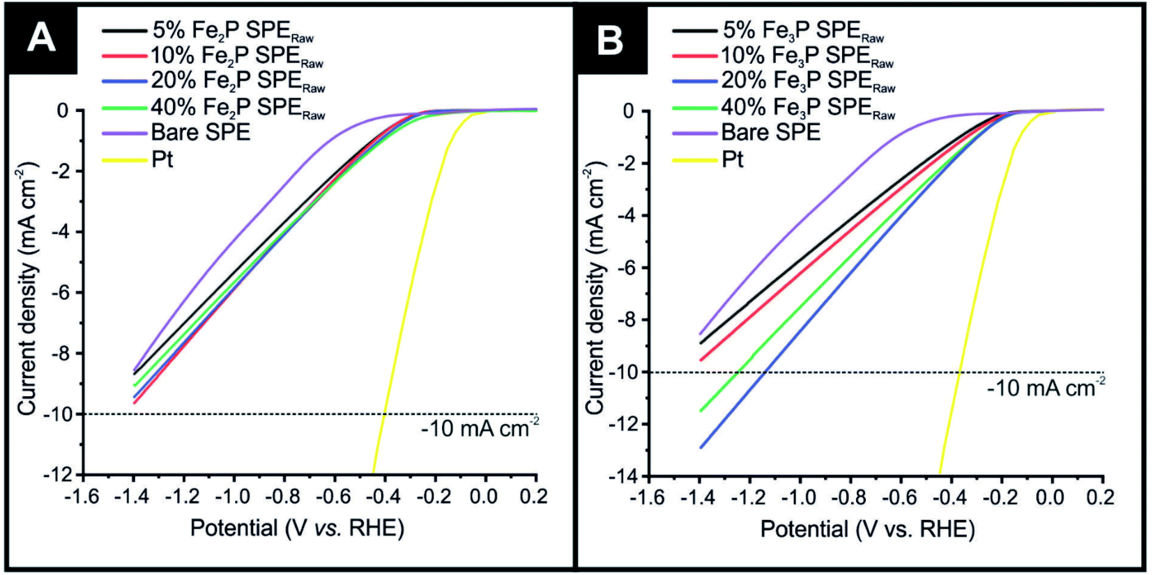 | ||
| Fig. 1 (A) Linear sweep voltammetry (LSV) exhibiting the onset potential of the HER, in the potential range +0.2 to −1.4 V (vs. RHE) for the Fe2P SPEs produced from raw powder: Fe2P SPE5%, Fe2P SPE10%, Fe2P SPE20%, Fe2P SPE40%, bare/unmodified SPE and polycrystalline Pt. (B) And for the Fe3P SPEs produced from raw powder: Fe3P SPE5%, Fe3P SPE10%, Fe3P SPE20%, Fe3P SPE40% bare/unmodified SPE and polycrystalline Pt. Scan rate: 25 mV s−1 (vs. RHE) in 0.5 M H2SO4. | ||
Fig. 1(B) also shows LSV obtained for the 5% Fe3P SPERaw, 10% Fe3P SPERaw, 20% Fe3P SPERaw and 40% Fe3P SPERaw, again, benchmarked against a bare SPE and a polycrystalline Pt electrode. HER onset potential values of −0.53, −0.14, −0.13, −0.11 and −0.11 V (vs. RHE) were exhibited by the bare SPE, 5% Fe3P SPERaw, 10% Fe3P SPERaw, 20% Fe3P SPERaw and 40% Fe3P SPERaw, respectively. The least electronegative HER onset potential was exhibited by the 20 and 40% Fe3P SPERaw due to the higher loading of Fe3P catalyst within SPEs. A higher achievable current density is observed within the Fe3P SPEs compared to the Fe2P SPEs, where the 20% Fe3P SPERaw and 40% Fe3P SPERaw required −1.13 and −1.24 V (vs. RHE) to reach −10 mA cm−2. This is likely due to the increase in ferric content, where a greater number of Fe–Fe bridge sites result in a faster heterogeneous electron transfer (HET) rate.25 It is evident that a 20% incorporation of Fe3P within SPEs is the optimal mass loading with no significant improvement with 40%, and in fact, is worse than the 20% incorporation, which is likely due to partial blockage of active sites at the electrode surface and reduced conductive electronic pathways within the graphite electrode.6,11,43 Note that further loadings of the Fe3P result in difficulties in screen-printing due to the change in rheology and represents the limit; this has seen multiple times for materials incorporated into bulk SPEs by our group. Given that the 20% Fe3P SPERaw is the nearest in HER activity to the optimal Pt electrode, this mass loading of Fe3P only was taken forward for further exploration towards the HER.
Next, ball-milling was utilised to try and tune/improve the HER kinetics of the Fe3P further, which is facilitated by reducing the average particle size and increasing porosity; such an approach has been previously reported for other materials.60–62 Consequently, raw Fe3P powder was ball milled over various time intervals (5, 10, 20 and 50 h) and the resultant powders incorporated into the bulk of bespoke SPEs and benchmarked against the HER within acidic media. Note that a full physicochemical characterization was performed on the raw and ball milled Fe3P powders utilized, as it is the focus of HER exploration within this paper (see Experimental section and ESI†), but not performed on the Fe2P powders.
Fig. 2 shows LSVs obtained for the Fe3P SPE5 h, Fe3P SPE10 h, Fe3P SPE20 h and Fe3P SPE50 h, benchmarked against a bare SPE and a polycrystalline Pt electrode. HER onset potential values of −0.53, −0.12, −0.11, −0.11 and −0.12 V (vs. RHE) are exhibited by the bare SPE, Fe3P SPE5 h, Fe3P SPE10 h, Fe3P SPE20 h and Fe3P SPE50 h, respectively. The applied potentials of: −1.04, −0.91, −0.84 and −1.14 V (vs. RHE) were required to reach −10 mA cm−2 for the Fe3P SPE5 h, Fe3P SPE10 h, Fe3P SPE20 h and Fe3P SPE50 h, respectively. The HER onset potentials displayed by the ball milled Fe3P SPEs show that the HER kinetics of each SPE have remained stable as a result of increased ball milling time. The applied potential required to reach −10 mA cm−2 for all Fe3P electrodes was greatly reduced with milling time, excluding the Fe3P SPE50 h BM, which has marginally increased. It is evident that there is an optimal duration of ball milling, where a 25.7% reduction in applied potential to reach −10 mA cm−2 is exhibited by the Fe3P SPE20 h BM compared to the un-milled variant. This is due to increasing ball-milling time leading to an increase in specific surface area and a decrease in crystal size and micropore diameter of the Fe3P powder. Note, that as the micropore diameter is reduced, porosity is increased with respect to increased micropore ratio. It is likely that the micropore diameter (nm) decreases up to 20 h of ball milling, then begins to plateau or increase moving towards 50 h. This is because there is an increase in the maximum distribution of nanoparticles (Pmax) after which porosity is reduced as a result of cluster formation.63 The Fe3P powder ball milled for 20 h possesses the greatest porosity and therefore the higher ratio of Fe–Fe bridge sites to Fe–P sites. The Fe3P SPE5 h, Fe3P SPE10 h, Fe3P SPE20 h and Fe3P SPE50 h exhibit specific activities of 0.296, 0.297, 0.314 and 0.306 A cm−2, respectively, hence displaying the optimal ball milling time of 20 h. Tafel analysis was used in a qualitative manner, in order assess whether there was an alteration in the HER reaction mechanism as the ball milling time increased. Tafel analysis extrapolated from the faradaic regions of the LSV's presented in Fig. 2 with values of 118.1, 88.5, 101.4, 95.6 and 96.4 mV dec−1 are exhibited by the bare SPE, Fe3P SPE5 h, Fe3P SPE10 h, Fe3P SPE20 h and Fe3P SPE50 h, respectively. This suggests that there is no change in the rate limiting HER step, which closely matches that expected for the Volmer step/mechanism. Last, the current literature has been surveyed with respect to transition metal phosphides (TMPs), as shown in the ESI (ESI Table T3†) where all other approaches have utilised drop-casting. It is evident that the our Fe3P bulk modified SPEs perform comparably with previous TMPs with our approach potentially offering a greater transition from academia to industry based upon that fact that these Fe3P SPEs can offer mass production and scales of economy.
 | ||
| Fig. 2 Linear sweep voltammetry (LSV) exhibiting the onset potential of the HER, in the potential range +0.2 to −1.4 V (vs. RHE) for the 20% Fe3P SPEs produced from ball milled (BM) powder: Fe3P SPE5 h BM, Fe3P SPE10 h BM, Fe3P SPE20 h BM, Fe3P SPE50 h BM, bare/unmodified SPE and polycrystalline Pt. Scan rate: 25 mV s−1 (vs. RHE) in 0.5 M H2SO4. | ||
Electrochemical performance of the Fe3P SPEs towards the HER under a weak (constant) magnetic field
The optimised Fe3P SPEs were next explored towards the HER under the effect of a weak (constant) magnetic field applied perpendicular (B−). As shown in Fig. 3, the 20% Fe3P SPERaw displayed the following potential values to reach −10 mA cm−2 of −1.13, −1.07, −1.09, −1.11 and −1.13 (vs. RHE) which correspond to the B values of: 0 (magnet off), 0.29, 0.33, 0.15 and 0.04 T, respectively. The potential values for the 20% Fe3P SPE20 h BM to reach −10 mA cm−2 of −0.84, −0.77, −0.74, −0.82 and −0.84 V (vs. RHE) correspond to the B values listed above. It is evident that applying a larger magnetic flux density beneficially alters the HER catalysis exhibited by the 20% Fe3P SPERaw where a 56% improvement, compared to the bare SPE, is observed at the maximum flux density (B).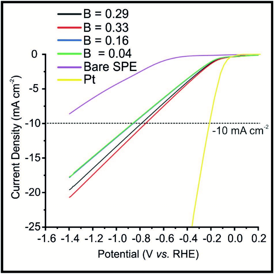 | ||
| Fig. 3 Linear sweep voltammetry (LSV) exhibiting the onset potential of the HER under an applied magnetic field, in the potential range +0.2 to −1.4 V (vs. RHE) for the Fe3P SPE20 h BM at the following magnetic flux densities: 0.29, 0.33, 0.16 and 0.04 T. Scan rate: 25 mV s−1 (vs. RHE) in 0.5 M H2SO4. | ||
The increase in HER activity can be visually observed, via being held at a potential of −0.50 (vs. RHE) in the ESI (see Video S1†), using the Fe3P SPE20 h BM. It is evident that hydrogen bubbles are produced at a faster rate upon the surface of the Fe3P SPE20 BM, as the magnetic flux density is increased, when the magnet is brought closer to the electrode surface. A suitable way to demonstrate this increased rate of hydrogen gas output is calculating the hydrogen turnover frequency (ToF) with and without the effect of magnetic field. ToF calculations, shown in the ESI,† for the Fe3P SPE20 h with and without a magnetic field, exhibit values of 2.72 × 10⁻⁷, 5.61 × 10⁻⁷, 5.67 × 10⁻⁷, 4.17 × 10⁻⁷ and 3.30 × 10⁻⁷ H2 per s per active site, corresponding to the following values of B: 0, 0.29, 0.33, 0.15 and 0.04 T respectively; this suggests that applying a magnetic field enhances the kinetics of the HER.
Commercial PEM electrolysis requires the use of cathodic catalysts that exhibit long-term stability and current retention in acidic conditions. Therefore, chronoamperometry, shown in ESI (Fig. S5†), was carried out using the Fe3P SPE20 h BM at −0.50 V (vs. RHE) for a duration of 24 h in 0.5 M H2SO4, in the presence of a magnetic field (B = 0.33 T). It is clear that the Fe3P SPE20 h BM retains nearly 100% of its current density at 2.98 mA cm−2 for 24 h, in exception to a drop in current density at 15 h to ca. 2 mA cm−2 until 20 h, where the current density returns to 2.98 mA cm−2.
Last, the reason for the increase of 56% and the improvement of the ToF under the application of a weak (constant) magnetic field needs to be surmised. It is important to ascertain whether the observed response (beneficial signal output with regards to a greater achievable HER curreny density) is due to the application of the magnetic field improving the electron transfer/heterogeneous rate kinetics between the electrode surface and the proton, or other factors. It is likely that the following factors contribute: (1) ferromagnetic materials, such as Fe3P utilised here, exhibit increased electron transfer efficiency due to higher energy electrons (as a result of the external magnetic field) within the conductive graphitic substrate transferring to the Fe3P active sites at a faster rate; (2) Fe3P possesses greatest porosity and larger surface area, after 20 h ball milling, therefore a higher number of distributed Fe–Fe bridge active sites where high energy electrons will have an increased number of electronic pathways to active sites; (3) the application of the magnetic field may also attributed to the Lorentz force, which induces convection via magnetohydrodynamic [MHD] and micro-MHD effects, resulting in diffusion layer thinning and removal of hydrogen gas bubbles from the electrode surface, increasing the availability of active sites on the electrode surface and increasing the ToF. Since hydrogen gas is diamagnetic, the direct effect of the magnetic field is likely to be relatively negligible. Thus, based on the observations herein, it is likely that the effect of the magnetic field improving the hydrogen evolution reaction is not kinetic/charge transfer in nature but rather that of mass-transport. This is a truly interesting field worthy of further insight.
Conclusions
To summarise, we have demonstrated the proficient activity of Fe3P SPE's towards the HER in an acidic electrolyte where the Fe3P material was incorporated into bulk modified SPEs. Ball-milling of the raw Fe3P powder prior to incorporation into the SPEs was utilised as a means to tune the HER kinetics of the Fe3P SPEs, by reducing average particle size. An external magnetic field was utilised to further optimise the HER activity exhibited by the ball-milled Fe3P SPEs, where a weak magnetic flux density resulted in a beneficial increase of 56%. The Fe3P SPE20 h BM exhibited excellent stability over the course of a 20 h chronoamperometric measurement at −0.50 V (vs. RHE) under a magnetic field (0.33 T), retaining 100% of its current density. The proficient HER activity and long term stability of the ball milled Fe3P SPEs in acidic conditions, under weak magnetic control, represents the first instance of SPEs utilised within a magnetic field, where applying a weak magnetic field reduces the requirement for costly magnetic components. This work opens up an entire field of unexplored research and demonstrates an advancement in the field of PEM electrolysis, helping transition this work closer to industrial uptake as the Fe3P bulk modified SPEs can be mass-produced and have scales of economy.Conflicts of interest
The authors declare no competing financial interest.Acknowledgements
This study is funded by Innovate UK (Reference: 11607) in cooperation with the European Marine Energy Centre (EMEC). Funding is also from the Engineering and Physical Sciences Research Council (Reference: EP/P007767/1 and EP/N0011877/1). The Manchester Fuel Cell Innovation Centre is funded by the European Regional Development Fund.References
- S. E. Hosseini and M. A. Wahid, Renewable Sustainable Energy Rev., 2016, 57, 850–866 CrossRef CAS.
- I. Dincer and C. Acar, Int. J. Hydrogen Energy, 2015, 40(34), 11094–11111 CrossRef CAS.
- World Nuclear Association, Heat Values of Various Fuels, https://www.world-nuclear.org/information-library/facts-and-figures/heat-values-of-various-fuels.aspx, accessed 16/01/2020 Search PubMed.
- F. Isorna, F. Segura and J. A. Marquez, Green hydrogen production methods. A review of solar-driven water splitting techniques, 2018 Search PubMed.
- T. R. Ayodele and J. L. Munda, Int. J. Hydrogen Energy, 2019, 44(33), 17669–17687 CrossRef CAS.
- J. P. Hughes, F. D. Blanco, C. E. Banks and S. J. Rowley-Neale, RSC Adv., 2019, 9(43), 25003–25011 RSC.
- P. S. Adarakatti, M. Mahanthappa, J. P. Hughes, S. J. Rowley-Neale, G. C. Smith, S. Ashoka and C. E. Banks, Int. J. Hydrogen Energy, 2019, 44(31), 16069–16078 CrossRef CAS.
- M. Karuppannan, Y. Kim, S. Gok, E. Lee, J. Y. Hwang, J.-H. Jang, Y.-H. Cho, T. Lim, Y.-E. Sung and O. J. Kwon, Energy Environ. Sci., 2019, 12(9), 2820–2829 RSC.
- S. J. Rowley-Neale, D. A. C. Brownson, G. C. Smith, D. A. G. Sawtell, P. Kelly and C. E. Banks, Nanoscale, 2015, 7(43), 18152–18168 RSC.
- S. Rowley-Neale, M. Ratova, L. Fugita, G. Smith, A. Gaffar, J. Kulczyk-Malecka, P. Kelly and C. Banks, ACS Omega, 2018, 3(7), 7235–7242 CrossRef CAS.
- S. J. Rowley-Neale, C. W. Foster, G. C. Smith, D. A. C. Brownson and C. E. Banks, Sustainable Energy Fuels, 2017, 1(1), 74–83 RSC.
- G. Hu, J. Li, P. Liu, X. Zhu, X. W. Li, R. N. Ali and B. Xiang, Appl. Surf. Sci., 2019, 463, 275–282 CrossRef CAS.
- J. Hao, W. Yang, Z. Zhang and J. Tang, Nanoscale, 2015, 7(25), 11055–11062 RSC.
- B.-W. Ahn, T.-Y. Kim, S.-H. Kim, Y.-I. Song and S.-J. Suh, Appl. Surf. Sci., 2018, 432, 183–189 CrossRef CAS.
- A. Sumboja, T. An, H. Y. Goh, M. Lübke, D. P. Howard, Y. Xu, A. D. Handoko, Y. Zong and Z. Liu, ACS Appl. Mater. Interfaces, 2018, 10(18), 15673–15680 CrossRef CAS.
- A. R. J. Kucernak and V. N. N. Sundaram, J. Mater. Chem. A, 2014, 2(41), 17435–17445 RSC.
- J.-S. Moon, J.-H. Jang, E.-G. Kim, Y.-H. Chung, S. J. Yoo and Y.-K. Lee, J. Catal., 2015, 326, 92–99 CrossRef CAS.
- B. You, N. Jiang, M. Sheng, M. W. Bhushan and Y. Sun, ACS Catal., 2016, 6(2), 714–721 CrossRef CAS.
- F. Du, Y. Zhang, H. He, T. Li, G. Wen, Y. Zhou and Z. Zou, J. Power Sources, 2019, 431, 182–188 CrossRef CAS.
- Z. Zhu, Y. Yang, Y. Guan, J. Xue and L. Cui, J. Mater. Chem. A, 2016, 4(40), 15536–15545 RSC.
- Y. Li, S. Niu, D. Rakov, Y. Wang, M. Cabán-Acevedo, S. Zheng, B. Song and P. Xu, Nanoscale, 2018, 10(15), 7291–7297 RSC.
- F. Wang, X. Yang, B. Dong, X. Yu, H. Xue and L. Feng, Electrochem. Commun., 2018, 92, 33–38 CrossRef CAS.
- H. Du, S. Gu, R. Liu and C. M. Li, Int. J. Hydrogen Energy, 2015, 40(41), 14272–14278 CrossRef CAS.
- Z. Gao, Q. Gao, Z. Liu, C. Zhang, X. Zhang, X. Liu, R. Wang and N. Li, RSC Adv., 2016, 6(115), 114430–114435 RSC.
- D. E. Schipper, Z. Zhao, H. Thirumalai, A. P. Leitner, S. L. Donaldson, A. Kumar, F. Qin, Z. Wang, L. C. Grabow, J. Bao and K. H. Whitmire, Chem. Mater., 2018, 30(10), 3588–3598 CrossRef CAS.
- D. E. Schipper, Z. Zhao, H. Thirumalai, A. P. Leitner, S. L. Donaldson, A. Kumar, F. Qin, Z. Wang, L. C. Grabow, J. Bao and K. H. Whitmire, Chem. Mater., 2018, 30(10), 3588–3598 CrossRef CAS.
- K. Persson, Materials Data on FeP (SG:62) by Materials Project, Energy, U. S. D. o., Ed., 2015 Search PubMed.
- E. Kha, S. Bhat, S.-C. Lee and S. Bhattacharjee, Cu-substituted Fe2P: An emerging candidates for magnetic RAM application. 2019 Search PubMed.
- K. Persson, Materials Data on Fe2P (SG:189) by Materials Project, Energy, U. S. D. o., Ed., 2016 Search PubMed.
- J. Wu, X. Y. Chong, R. Zhou, Y. H. Jiang and J. Feng, RSC Adv., 2015, 5(100), 81943–81956 RSC.
- K. Persson, Materials Data on Fe3P (SG:82) by Materials Project, Energy, U. S. D. o., Ed., 2016 Search PubMed.
- L. Elias and H. A. Chitharanjan, Electrocatalysis, 2017, 8(4), 375–382 CrossRef CAS.
- F. A. Garcés-Pineda, M. Blasco-Ahicart, D. Nieto-Castro, N. López and J. R. Galán-Mascarós, Nat. Energy, 2019, 4(6), 519–525 CrossRef.
- V. Gatard, J. Deseure and M. Chatenet, Curr. Opin. Electrochem., 2020, 23, 96–105 CrossRef CAS.
- Y. Li, L. Zhang, J. Peng, W. Zhang and K. Peng, J. Power Sources, 2019, 433, 226704 CrossRef CAS.
- M. Sheikholeslami and D. D. Ganji in External Magnetic Field Effects on Hydrothermal Treatment of Nanofluid, ed. M. Sheikholeslami and D. D. Ganji, William Andrew Publishing, 2016, pp. 1–47 Search PubMed.
- N. Leventis and X. Gao, Anal. Chem., 2001, 73(16), 3981–3992 CrossRef CAS.
- M. D. Kuz'min and M. Richter in Encyclopedia of Materials: Science and Technology, ed. K. H. J. Buschow, R. W. Cahn, M. C. Flemings, B. Ilschner, E. J. Kramer, S. Mahajan and P. Veyssière, Elsevier, Oxford, 2007, pp. 1–7 Search PubMed.
- M.-Y. Lin, L.-W. Hourng and C.-W. Kuo, Int. J. Hydrogen Energy, 2012, 37(2), 1311–1320 CrossRef CAS.
- Z. Zeng, T. Zhang, Y. Liu, W. Zhang, Z. Yin, Z. Ji and J. Wei, ChemSusChem, 2018, 11(3), 580–588 CrossRef CAS.
- E. J. Lisher, C. Wilkinson, T. Ericsson, L. Haggstrom, L. Lundgren and R. Wappling, J. Phys. C: Solid State Phys., 1974, 7(7), 1344–1352 CrossRef CAS.
- H. Shin, S. Lee, H. S. Jung and J.-B. Kim, Ceram. Int., 2013, 39(8), 8963–8968 CrossRef CAS.
- S. J. Rowley-Neale, D. A. C. Brownson, G. C. Smith, D. A. G. Sawtell, P. J. Kelly and C. E. Banks, Nanoscale, 2015, 7(43), 18152–18168 RSC.
- S. J. Rowley-Neale, G. C. Smith and C. E. Banks, ACS Appl. Mater. Interfaces, 2017, 9(27), 22539–22548 CrossRef CAS.
- A. G.-M. Ferrari, C. W. Foster, P. J. Kelly, D. A. C. Brownson and C. E. Banks, Biosensors, 2018, 8(2), 53 CrossRef CAS.
- K. Li, C. Zhang, X. Li, Y. Du, P. Yang and M. Zhu, Catal. Today, 2018, 335, 173–179 CrossRef.
- C. Wang, W. D. Wu, Y. Wang, D. Xu and F. Yan, New J. Chem., 2017, 41(15), 7392–7399 RSC.
- X. Wang, W. Xiao, J. Zhang, Z. Wang and X. Jin, Electrochem. Commun., 2019, 102, 52–56 CrossRef CAS.
- B. Madavali, J.-H. Lee, J. K. Lee, K. Y. Cho, S. Challapalli and S.-J. Hong, Powder Technol., 2014, 256, 251–256 CrossRef CAS.
- E. Lisher, C. Wilkinson, T. Ericsson, L. Haggstrom, L. Lundgren and R. Wappling, J. Phys. C: Solid State Phys., 2001, 7, 1344 CrossRef.
- X. Lai, F. Zhu, Y. Liu, W. Bi, J. Zhao, E. E. Alp, M. Y. Hu, D. Zhang, S. Tkachev, M. H. Manghnani, V. B. Prakapenka and B. Chen, Earth Planet. Sci. Lett., 2020, 531, 115974 CrossRef CAS.
- C. Pirim, M. A. Pasek, D. A. Sokolov, A. N. Sidorov, R. D. Gann and T. M. Orlando, Geochim. Cosmochim. Acta, 2014, 140, 259–274 CrossRef CAS.
- Y. Wang, L. Zhang, H. Li, Y. Wang, L. Jiao, H. Yuan, L. Chen, H. Tang and X. Yang, J. Power Sources, 2014, 253, 360–365 CrossRef CAS.
- C. Y. Son, I. H. Kwak, Y. R. Lim and J. Park, Chem. Commun., 2016, 52(13), 2819–2822 RSC.
- T. Plachy, E. Kutalkova, M. Sedlacik, A. Vesel, M. Masar and I. Kuritka, J. Ind. Eng. Chem., 2018, 66, 362–369 CrossRef CAS.
- F.-X. Ma, C.-Y. Xu, F. Lyu, B. Song, S.-C. Sun, Y. Y. Li, J. Lu and L. Zhen, Adv. Sci., 2019, 6(3), 1801490 CrossRef.
- G. Cho, H. Kim, Y. S. Park, Y.-K. Hong and D.-Y. Ha, Int. J. Hydrogen Energy, 2018, 43(24), 11326–11334 CrossRef CAS.
- S. Yao, V. Forstner, P. W. Menezes, C. Panda, S. Mebs, E. M. Zolnhofer, M. E. Miehlich, T. Szilvási, N. A. Kumar, M. Haumann, K. Meyer, H. Grützmacher and M. Driess, Chem. Sci., 2018, 9(45), 8590–8597 RSC.
- J. Scremin, I. V. J. d. Santos, J. P. Hughes, A. G.-M. Ferrari, E. Valderrama, W. Zheng, X. Zhong, X. Zhao, E. J. R. Sartori, R. D. Crapnell, S. J. Rowley-Neale and C. E. Banks, Nanoscale, 2020,(12), 18214–18224 RSC.
- M. Ma, K. Chen, J. Jiang, X. Yang, H. Wang, H. Shao, J. Liu and L. Ouyang, Inorg. Chem. Front., 2020, 7(4), 918–929 RSC.
- L.-F. Zhang, X. Ke, G. Ou, H. Wei, L.-N. Wang and H. Wu, Sci. China Mater., 2017, 60(9), 849–856 CrossRef CAS.
- X. Liu, Y. Guo, W. Zhan and T. Jin, Catalysts, 2019, 9, 240 CrossRef.
- T. T. Bui, X. Q. Le, D. P. To and V. T. Nguyen, Adv. Nat. Sci.: Nanosci. Nanotechnol., 2013, 4(4), 045003 Search PubMed.
Footnote |
| † Electronic supplementary information (ESI) available. See DOI: 10.1039/d0ra10150h |
| This journal is © The Royal Society of Chemistry 2021 |