DOI:
10.1039/D0RA09620B
(Paper)
RSC Adv., 2021,
11, 7466-7478
Fabrication and characterization of 3D printable nanocellulose-based hydrogels for tissue engineering†
Received
12th November 2020
, Accepted 2nd February 2021
First published on 15th February 2021
Abstract
Cellulose nanocrystal (CNC)-based hydrogels are considered attractive biomaterials for tissue engineering due to their excellent physicochemical properties. Hydrogels of alginate and gelatin were prepared with or without CNCs and printed using a CELLINK® BIOX 3D bio-printer. The 3D-printed scaffolds were characterized by Fourier transform infrared (FTIR) spectroscopy, Raman spectroscopy, transmission electron microscopy (TEM), and scanning electron microscopy (SEM). Improved mechanical strength was observed in the composite scaffolds compared to the pure polymer scaffolds. Fabricated scaffolds exhibited superior swelling potential; this property is profoundly affected by the CNC content of hydrogels. Biocompatibility of the fabricated scaffolds was monitored in the presence of human bone marrow-derived mesenchymal stem cells (hBMSCs) using the WST-1 assay. Notably, better cell viability was observed in the composite scaffolds than in the control, indicating improved biocompatibility of composites. Cells were healthy and adhered appropriately to the surface of the scaffolds. Mineralization potential of the prepared scaffolds was evaluated by the alizarin red S (ARS) staining technique in the presence of hBMSCs after 7 and 14 days of treatment. Enhanced mineral deposition was observed in the composite scaffolds compared to the control, indicating superior composite mineralization potential. Upregulation of osteogenic-associated genes was observed in the scaffold-treated groups relative to the control, showing superior scaffold osteogenic potential. These results demonstrate that 3D-printed scaffolds are potential candidates for bone tissue engineering applications.
1. Introduction
Reconstruction of injured bone is one of the most significant challenges in medical science.1,2 Allografts and autografts are applied to treat injured bone. However, this process has some drawbacks. Bone tissue engineering is considered a promising alternative technique and is being explored as a replacement for conventional therapies. Naturally derived polymers such as collagen, silk fibroin, glucan, cellulose, alginate, gelatin, chitosan, and hyaluronic acid have been extensively used as biomaterials for tissue engineering.2–6 Hydrogels based on naturally derived biomaterials can be used for biomedical applications,7–9 and their properties resemble the native extracellular matrix (ECM) that provides appropriate support for enhanced cellular activity.10 Alginate and gelatin are considered attractive materials for tissue regeneration due to their excellent biocompatibility and favorable chemical structure.2,4,11,12 Alginate is a block copolymer containing β-D-mannuronic acid and α-L-glucuronic acid units, and it is easily cross-linked with divalent cations.12,13 However, alginate-based hydrogels exhibit low viscosity, which restricts their applications in 3D printing.14,15 Alginate has low cellular activity, and therefore it must be blended with other biocompatible polymers such as gelatin to make 3D printable bio-ink for tissue engineering. Gelatin is derived from collagen, and gelatin-incorporated alginate matrix exhibits superior cellular activity. Alginate/gelatin-based hydrogels have attracted significant interest in tissue engineering because of their superior physicochemical properties and enhanced bioactivity.4,16 In conventional hydrogel scaffolds, a lack of controlled inner structure and morphology characterizes their 3D space. A 3D printing approach can generate scaffolds with precise structure and morphology, and printing cultured cells with the materials provides a fascinating pathway that can be applied as tissue-engineered constructs for different applications.17
Different nanomaterials such as metals and their oxides, carbon nanotubes (CNTs), graphene, zeolite, and nanocellulose are often utilized to improve the properties of pure polymers.18–20 Cellulose is one of the most abundant natural polymers on Earth, occurring in the cell walls of plants and in some bacteria. It has an amorphous, crystalline structure. Nanocellulose is considered a promising material in tissue engineering owing to its unique physicochemical properties.21 The acid hydrolysis of cellulose generates highly crystalline nanomaterials known as cellulose nanocrystals (CNCs).4,21–24 Rice husk, bamboo, potato tuber, sugar beet, wheat straw, cotton, wood, bacteria, and algae are frequently used to obtain CNCs by acidic hydrolysis.25–27 An enhancement in the gelation of alginate–gelatin hydrogel occurs in the presence of CNCs through the increased interaction.4,16,28 Improved mechanical strength has been noted in CNC-based composites compared to pure polymers.23 For 3D printing, CNC-based bio-inks have the advantage of a higher solid content due to their lower aspect ratio relative to cellulose nanofibrils (CNFs), as well as an easier surface functionalization.29
In this work, alginate/gelatin/CNC hydrogels were prepared through the physical cross-linking process as a 3D printable bio-ink for tissue engineering. Interaction between the components was analyzed by FTIR spectroscopy. The mechanical strength of the printed scaffolds was evaluated using a universal tensile machine (UTM). Biocompatibility of the scaffolds was determined by the WST-1 assay in human bone-marrow-derived mesenchymal stem cells (hBMSCs). Enhanced mineral deposition occurred in the composite scaffolds compared to the control, indicating better composite mineralization potential. Thus, printed scaffolds can be explored for stem cell differentiation in tissue engineering. The applicability of alginate-based hydrogels has been previously reported. The advantages of the developed material were its stability without cross-linking agents and its improved osteogenic potential.
2. Experimental section
2.1. Materials
The cotton pulps-derived CNCs (10–20 nm width and 50–400 nm length) were received from Cellulose Laboratories, Canada. Sodium alginate and gelatin were purchased from Sigma-Aldrich (purity ≥ 98%). All chemicals were used without further purification. The CELLINK® BIOX 3D bio-printer was purchased from CELLINK Corporation, Sweden.
2.2. Hydrogel preparation
The hydrogels were prepared as previously described somewhere else with some modifications.16 The Alg–Gel hydrogels were prepared by blending the calculated amounts of sodium alginate (2% w/v) and gelatin (3% w/v) in an aqueous condition. For this, the aqueous solution of sodium alginate was prepared and stirred at 70 °C for 30 min. The solution was cooled to 45 °C, and the addition of the required amounts of gelatin was accomplished in the solution with continuous mechanical stirring for 30 min. The Alg–Gel–CNCs hydrogels were fabricated similarly by adding different amounts of CNCs (1, 2, and 4%) into the blend solution. The prepared samples were kept in a refrigerator at 4 °C for 12 h to initiate gelation. The hydrogel compositions are given in Table 1. The pure polymer and composite scaffolds were denoted by Alg–Gel, and Alg–Gel-x, respectively. Where x is the percentage weight of CNCs in the polymer matrix.
Table 1 The details of the chemical compositions of the fabricated hydrogels
| Composition |
Alginate% (w/v) |
Gelatin% (w/v) |
CNCs% (w/w) |
| Alg–Gel |
2 |
3 |
0 |
| Alg–Gel-0.5 |
2 |
3 |
0.5 |
| Alg–Gel-1 |
2 |
3 |
1 |
| Alg–Gel-2 |
2 |
3 |
2 |
| Alg–Gel-4 |
2 |
3 |
4 |
2.3. Printing of hydrogel
The prepared hydrogels were filled into plastic printing cartridges (CELLINK Corporation, Sweden). The printing was performed with CELLINK BIO-X (CELLINK Corporation, Sweden). The Solidworks software (http://www.solidworks.com, Dassault Biosystems, France) was utilized to design the printing structure. The pre-designed structures with four perpendicular layers were printed, and the printing parameters are given in Table 2. A few seconds to minutes led to gel curing. The printed scaffolds were freeze-dried and kept in a vacuum desiccator for further experiments.
Table 2 The parameters used in the 3D printing of the different hydrogels
| Condition |
Alg–Gel |
Alg–Gel-0.5 |
Alg–Gel-1 |
Alg–Gel-2 |
Alg–Gel-4 |
| Cartridge needle (G) (mm) |
27 G (0.2) |
27 G (0.2) |
27 G (0.2) |
27 G (0.2) |
27 G (0.2) |
| Printing pressure (kPa) |
80 |
100 |
400 |
600 |
600 |
| Printing speed (mm s−1) |
8 |
8 |
8 |
8 |
8 |
| Printing temperature (°C) |
30 |
30 |
30 |
30 |
30 |
| Print bed temperature (°C) |
6 |
6 |
6 |
6 |
6 |
2.4. Morphological and composition analysis
The surface morphologies of the fabricated scaffolds were examined by scanning electron microscopy (SEM) (S-4800, Hitachi, Tokyo, Japan). For this, the scaffolds were sputter-coated with platinum for 250 s at 15 mA, and morphologies were captured with an accelerating voltage of 5.0 kV cm−1. The interaction between Alg–Gel with CNCs was monitored with the FTIR spectroscopy (Perkin Elmer, UK) in the transmitted mode in the wavenumber range of 500–4000 cm−1 at a resolution of 4 cm−1. The solid printed scaffolds were taken for the FTIR measurement. Raman spectra of the developed scaffolds were recorded on Horiba Jobin Yvon using laser light of wavelength 532 nm.
2.5. Mechanical strength
The mechanical strength of the printed scaffolds was evaluated using a universal tensile machine (UTM) (MCT-1150, Japan) in the elongation mode with the elongation rate of 10 mm min−1. All experiments were performed in triplicate (n = 3).
2.6. Rheological analysis
The rheological analysis of the developed hydrogels and the 3D-printed scaffolds was performed with an ARES-G2 rheometer (TA Instruments, New Castle, Delaware, USA), with a 6 mm parallel plate at different temperatures (25, 30, and 35 °C). The developed materials were characterized by flow and temperature sweep.
2.7. Swelling test
The swelling efficiency of the printed scaffolds was determined in distilled water and phosphate-buffered saline (PBS) solution at room temperature after different periods of soaking. For this, a predetermined weight of the dry scaffolds was dipped into water and removed after a fixed time period. The excess water from the surface of the scaffolds was removed with tissue paper, and the weight of hydrated scaffolds was taken. The samples were again immersed in water, and the process was repeated for the desired periods. The swelling efficiency was calculated with the following equation,
where, Wdry and Wwet are the weight of the printed scaffolds under dry and hydrated conditions, respectively. The swelling efficiency of the 3D-printed scaffolds in PBS solution was evaluated in a similar method to water.
2.8. Cell culture
The hBMSCs were received from the Korean Cell Line Bank (KCLB) (Seoul National University), Republic of Korea. The cells were cultured as previously reported somewhere else.23 In brief, the cells were cultured in Dulbecco's Modified Eagle Medium (DMEM; Welgene Inc., Republic of Korea) having 10% fetal bovine serum (FBS) (Welgene Inc., Republic of Korea), and 1% antibiotic (Anti–Anti; 100×, Gibco-BRL, USA) at 37 °C in a humidified atmosphere containing 5% CO2 (Steri-Cycle 370 Incubator; Thermo-Fischer Scientific, USA). The old media were replaced with fresh media after three days. At ∼70–80% of confluency, the cells were detached, counted, and passaged with 1 mL of 0.25% trypsin–ethylenediaminetetraacetic acid (EDTA) (Gibco, USA) solution. Passage three were used for the primary cell culture.
2.9. Cell viability
The biocompatibility of the printed scaffolds was evaluated by WST-1 assay technique in the presence of hBMSCs after different periods of treatment. The cells (1 × 10⁴) were placed in a 96-well plate and incubated in the 5% CO2 environment at 37 °C for 1, 3, and 5 days. After the treatment, the cells were washed with PBS and treated with WST-1 reagent. The WST-1 treated cells were further incubated for 2 h, and the concentrations of the formed formazan were assessed by a spectrophotometer (Infinite® M Nano 200 Pro; TECAN, Switzerland) at 450 nm of absorbance. All measurements were performed in triplicate (n = 3), and data are presented at mean ODs ± standard deviations. Statistical significance was considered at *p < 0.05. The samples were sterilized by the UV light treatment.
2.10. Cell morphology
The cell morphologies were examined by fluorescence microscopy (DMi8 Series, Leica Microsystems, Germany) after 5 days of treatment. The cells (2 × 10⁴) were cultured in the 35 × 15 mm dish for the required periods, followed by PBS washing. The cells were fixed using 4% paraformaldehyde (PFA) (Sigma-Aldrich, USA). The fixed cells were washed with PBS and permeabilized through 0.1% Triton-X 100 for 10 min, followed by blocking with 1% bovine serum albumin (BSA) (Sigma-Aldrich, USA) for 60 min. After this, the cells were stained with 200 μL of Alexa Fluor 488-conjugated phalloidin (F-Actin Probe; Invitrogen, Thermo-Fischer Scientific, USA) for 20 min, and the nucleus was counterstained by 4′,6-diamino-2-phenylindole dihydrochloride (DAPI) (Sigma-Aldrich, USA) for 5 min. The excess stains were removed by washing with PBS, followed by mounting with 1 drop of Prolong® Antifade (Invitrogen, Thermo-Fischer Scientific, USA), and images were captured using an inverted fluorescence microscope. The fluorescence intensity was measured with Leica Microsystems Suite X software (Leica Microsystems, Germany).
2.11. Mineralization study
The mineralization potential of the printed scaffolds was evaluated with the alizarin red-S (ARS) staining technique in the presence of hBMSCs after 7 and 14 days of treatment, as previously reported somewhere else.30 In brief, the cells (4 × 10⁶) were placed into the cultured media and incubated for the desired periods. The media without any scaffolds were considered as control. The old media were replaced with fresh media after three days. After incubation, the treated cells were washed with PBS and fixed by 70% ethanol solution for 15 min at room temperature. The fixed cells were treated with 40 mM ARS (pH 4.2, Sigma-Aldrich, USA) solution for 10 min. The excess stain was removed by washing with distilled water. The nodule formation was examined by an optical microscope (Zeiss Optical Microscope, Germany). The quantitative values of the mineralized nodule were measured by taking an absorbance with a spectrophotometer at 562 nm after de-staining the cultured media with 500 μL of de-staining solution (pH 7.0) having 10% of cetylpyridinium chloride (Sigma-Aldrich, USA) and 10 nM of sodium phosphate (Sigma-Aldrich, USA). All measurements were performed in triplicate (n = 3), and data are presented at mean ODs ± standard deviations. Statistical significance was considered at *p < 0.05.
2.12. Alkaline phosphatase activity
For ALP staining, the cells (4 × 10⁴) were incubated with Alg–Gel-1 scaffolds in a 24-well plate for 14 days. Cultured media without scaffold were considered as controls. After that, the plate was washed with PBS and fixed with 10% paraformaldehyde solution for 30 s. The fixed cells were incubated with 0.1% Triton X-100 for 5 min and stained with Leukocyte Alkaline Phosphatase Kit (Sigma-Aldrich, USA) as per manufacturer's instructions. The stain cells were washed with water, and images of ALP positive cells were capture by a light microscope. The ALP activity was quantified by measuring the intensity of positive cells with ImageJ software (ImageJ v1.8, NIH, Bethesda, USA).
2.13. Gene expression analysis
The expression of the osteogenic associated gene markers in hBMSCs was evaluated by the real-time polymerase chain reaction (qPCR) technique after 7 and 14 days of incubation as earlier reported.31 For this, the cells (4 × 10⁴) were cultured with or without scaffolds for the desired periods. The RNA was extracted by TRIzol® reagent (Thermo-Fischer Scientific, USA) as per the manufacturer's guidelines. The purity and concentrations of the extracted RNA were monitored by a spectrophotometer (Infinite® M Nano 200 Pro; TECAN, Switzerland). The cDNA was synthesized using the extracted RNA with reverse transcriptase (Superscript II RTase; Invitrogen, Gaithersburg, MD) and SYBR Green Master Mix (Bio-Rad, USA). The Bio-Rad Real-Time PCR (CFX96™ Maestro Real-Time System, Bio-Rad, USA) was utilized to quantify the mRNA expression. All experiments were performed in triplicate and normalized with housekeeping gene beta-actin (β-actin). The primer sets used here are listed in Table 3.
Table 3 List of the primer sets were used herea
| Genes |
GenBank accession no. |
Sequences (5′ to 3′) |
| HPRT, hypoxanthine guanine phosphoribosyl transferase; Runx2, runt-related transcription factor x2; ALP, alkaline phosphatase; BSP, bone sialoprotein; OPN, osteopontin. |
| HPRT |
NM_000194 |
GGCTATAAGTTCTTTGCTGACCTG CCACAGGGACTAGAACACCTGCTA |
| Runx2 |
NM_001146038 |
CGCACGACAACCGCACCAT CAGCACGGAGCACAGGAAGTT |
| ALP |
NM_007431 |
CCAACTCTTTTGTGCCAGAGA GGCTACATTGGTGTTGAGCTTTT |
| BSP |
L09555 |
AACTTTTATGTCCCCCGTTGA TGGACTGGAAACCGTTTCAGA |
| OPN |
J04765 |
TGAAACGAGTCAGCTGGATG TGAAATTCATGGCTGTGGAA |
2.14. Statistical analysis
Statistical analysis was performed with one-way ANOVA to determine the significant difference between different groups using Origin Pro 9.0 software (Origin Pro v9.0, USA). Data were shown as mean ± standard deviations. All experiments were accomplished in triplicate (n = 3), and statistical significance was considered as *p < 0.05.
3. Results and discussion
3.1. Interaction and morphological analysis
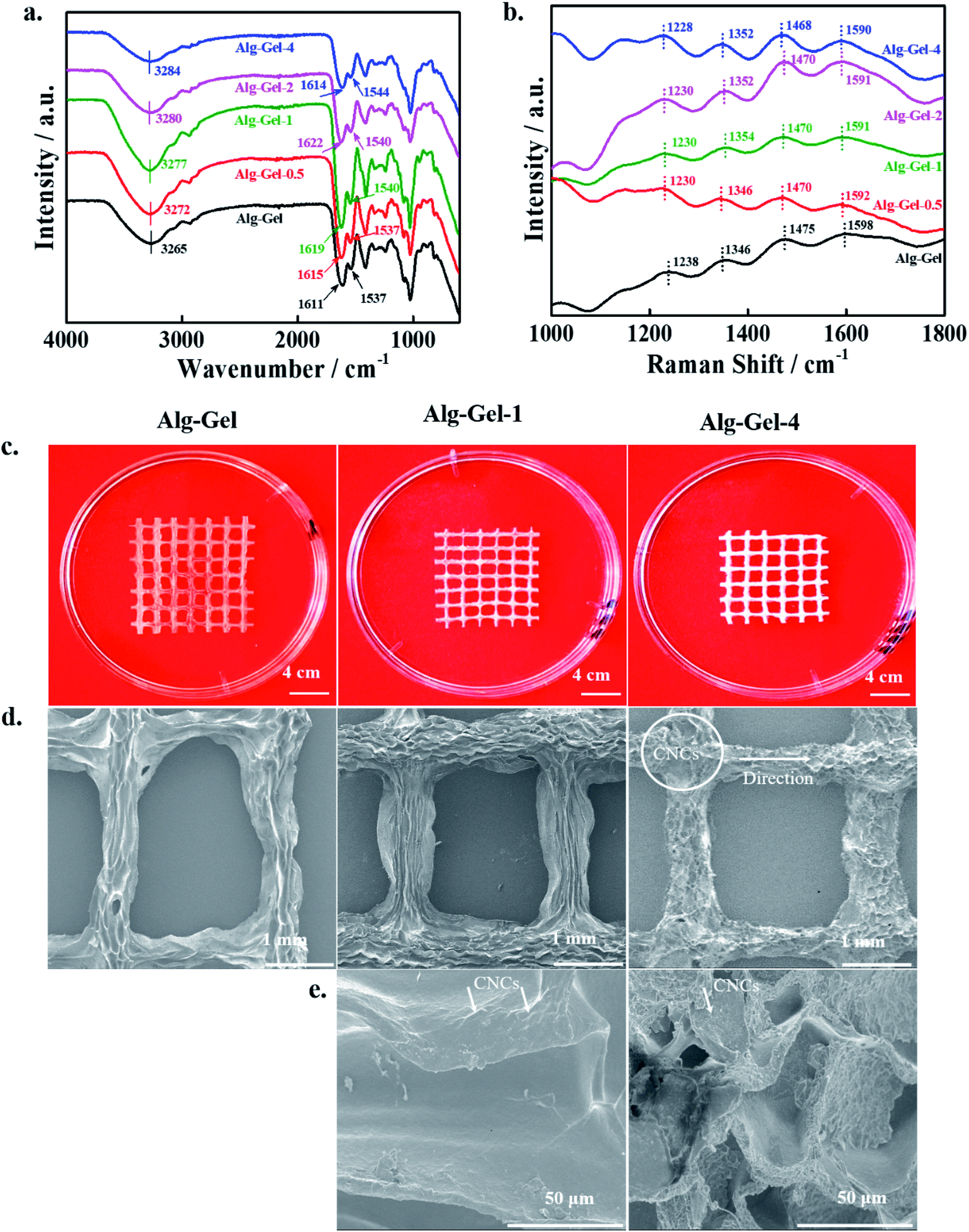
A schematic illustration of the preparation of the hydrogels is shown in Fig. 1a. We examined gelation in the hydrogel in the reverse mode of the reaction vial. Photographs of the reaction vials before and after gelation are shown in Fig. 1b. No motion was observed in the solution after 12 h of incubation at 4 °C, indicating complete gelation. The different parts of the 3D printing machine with printed scaffolds are shown in Fig. 1c. The interaction between the Alg–Gel matrix and CNCs was monitored by FTIR spectroscopy, and the spectra are presented in Fig. 2a. The appearance of the broad FTIR absorption peak in the Alg–Gel at 3265 cm−1 suggests the presence of intermolecular hydrogen-bonded hydroxyl (–OH) and amino (–NH2) groups in the matrix, which shifted towards a higher wavenumber in the composite hydrogels.32,33 This shift (3265 → 3284 cm−1) is due to the strong interaction between the polymer matrix and the incorporated CNCs. The FTIR absorption peak at 1611 cm−1 indicates the presence of carbonyl (![[double bond splayed left]](https://www.rsc.org/images/entities/char_e009.gif) C
C![[double bond, length as m-dash]](https://www.rsc.org/images/entities/char_e001.gif) O) groups in the Alg–Gel. This peak was further shifted towards higher wavenumbers in the composite hydrogels. This can be attributed to increased interaction between the polymer matrix and CNCs. The absorption peak at 1537 cm−1 shows the C–N stretching vibration mode of amide groups, in which absorption is shifted in the high wavenumber region in the composite hydrogel compared to the pure polymer hydrogel. Based on FTIR results, we assumed that hydrogen bonding was the major interaction between the polymer matrix and incorporated CNCs. Raman spectra of the 3D-printed scaffolds are shown in Fig. 2b. The Raman spectrum was also done for qualitative examination to assess how the components interacted in the composite. The Raman spectrum of polymer (Alg–Gel) scaffolds can be separated into two sections: the vibrations of the polymer backbone (<1300 cm−1) and carboxylate groups' ≥1300 cm−1. A significant Raman shift (1598 → 1590) was observed in the composite scaffolds compared to the polymer scaffold. The interaction of CNCs with the functional groups (prominently in the COO− groups) of the polymer chains is responsible for this peak shifting in the composite scaffolds. A Raman shift in the alginate polymer's carboxylate groups has also been previously reported due to the components' interaction.34,35 Significant Raman shift of the polymer backbone was also observed in the composite scaffolds, showing that the developed hydrogels are highly interactive.
O) groups in the Alg–Gel. This peak was further shifted towards higher wavenumbers in the composite hydrogels. This can be attributed to increased interaction between the polymer matrix and CNCs. The absorption peak at 1537 cm−1 shows the C–N stretching vibration mode of amide groups, in which absorption is shifted in the high wavenumber region in the composite hydrogel compared to the pure polymer hydrogel. Based on FTIR results, we assumed that hydrogen bonding was the major interaction between the polymer matrix and incorporated CNCs. Raman spectra of the 3D-printed scaffolds are shown in Fig. 2b. The Raman spectrum was also done for qualitative examination to assess how the components interacted in the composite. The Raman spectrum of polymer (Alg–Gel) scaffolds can be separated into two sections: the vibrations of the polymer backbone (<1300 cm−1) and carboxylate groups' ≥1300 cm−1. A significant Raman shift (1598 → 1590) was observed in the composite scaffolds compared to the polymer scaffold. The interaction of CNCs with the functional groups (prominently in the COO− groups) of the polymer chains is responsible for this peak shifting in the composite scaffolds. A Raman shift in the alginate polymer's carboxylate groups has also been previously reported due to the components' interaction.34,35 Significant Raman shift of the polymer backbone was also observed in the composite scaffolds, showing that the developed hydrogels are highly interactive.
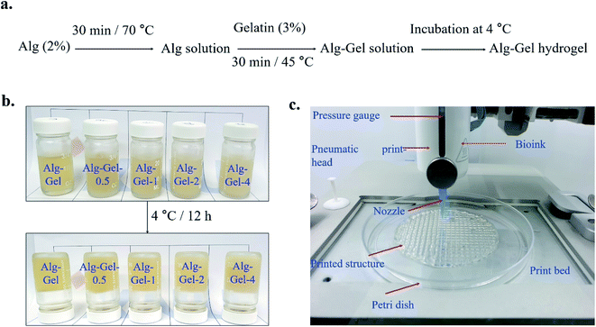 |
| | Fig. 1 (a) Schematic presentation for the fabrication of hydrogels, (b) the fabricated hydrogels before and after the incubation at 4 °C for 12 h, and (c) demonstration of the different parts of the printing machine with 3D-printed construct. | |
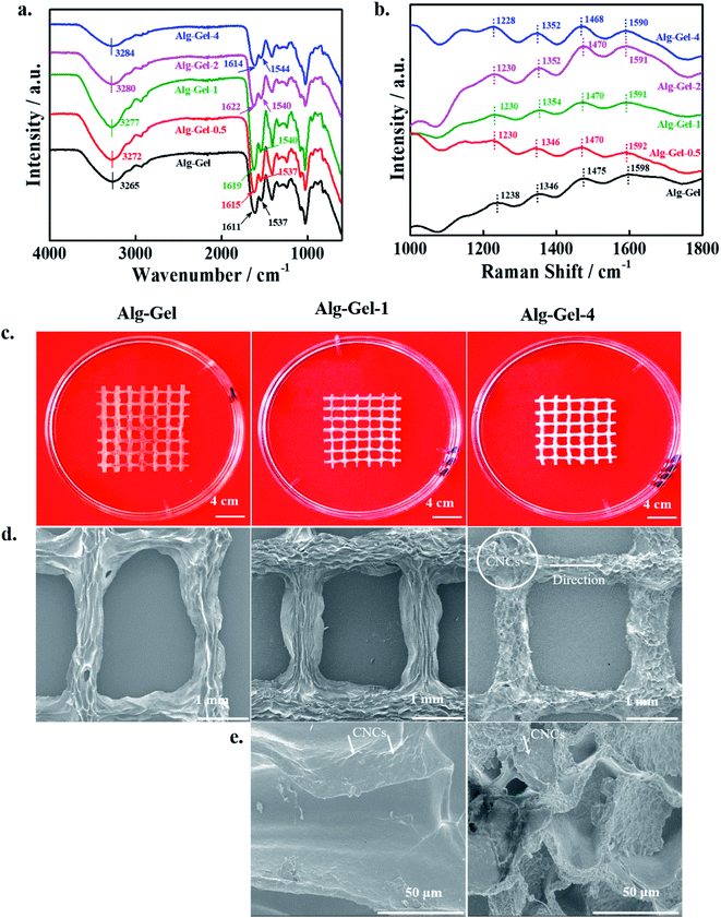 |
| | Fig. 2 Spectroscopic characterizations of the printed scaffolds, (a) the FTIR spectra, (b) Raman spectra of the 3D-printed pure polymer and its indicated composite scaffolds, (c) the photographs of the 3D-printed scaffolds under dry conditions, (d) SEM morphologies of the corresponding printed scaffolds, and (e) SEM morphologies of composite scaffolds at higher magnification at the junction of the scaffolds. | |
Freeze-dried images of the indicated 3D-printed scaffolds are shown in Fig. 2c. No significant collapse in the printed scaffolds' cell wall occurred in the dry condition, indicating that freeze-dried scaffolds have retained their morphology. Top-view SEM images of the freeze-dried 3D-printed scaffold surfaces are shown in Fig. 2d. The bridge and junction regions were easily identified in the printed scaffolds. The printing direction and layered morphology can be observed in the bridge region of the printed scaffolds. The composite scaffolds exhibited a rough surface morphology compared to the pure polymer scaffold; this roughness is believed to be a favorable structure for improved cellular activity by enhancing the diffusion rates of nutrients and other metabolic products in and out of the scaffolds. Magnified SEM morphologies of the corresponding composite scaffolds at the junction are shown in Fig. 2e. The CNC network can be observed in the printed scaffolds, which are embedded in the polymer matrix, indicating the effective dispersion of CNCs. Magnified SEM image indicates that the developed scaffolds were highly porous (∼85%) with a varying pore size of ∼20–42 μm. The orientation of nanomaterials has significant effects on cellular activity. Optical microscopy images of the saturated, swelled scaffolds are shown in ESI Fig. 1.† The fabricated scaffolds maintained their printed structure in the swelling condition, and the composite scaffolds exhibited a rougher morphology compared to the pure polymer scaffolds.
3.2. Mechanical strength
The mechanical strength of the 3D-printed scaffolds was evaluated by a UTM in the tensile mode, and the obtained stress–strain curves are shown in Fig. 3a. The mechanical strength of the materials provides important information associated with their utility ranges. Improved mechanical strength was observed in the composite scaffolds compared to the pure polymer scaffold, indicating the positive effects of incorporated CNCs. The mechanical behavior of the scaffolds is strongly affected by their physicochemical properties, dispersion of the incorporated nanomaterials, and interactions with the polymer matrix.36 An enhancement in the modulus values (obtained from the slope of the curve's initial linear region) was observed in the composite scaffolds relative to the pure polymer scaffold. Composite scaffolds exhibited higher toughness values (calculated from the area of the curve) compared to pure polymer scaffolds. The quantitative values of the modulus and toughness of the printed scaffolds are shown in Fig. 3b. The higher modulus value of the composite scaffolds is due to the greater interaction between the Alg–Gel matrix and CNCs, which facilitates the effective load transfer from the polymer matrix to the CNCs during measurement.37 The modulus values increased with increasing CNC content in the Alg–Gel matrix, indicating better interfacial interaction. The yield point was 0.18, 0.25, 0.47, 3.33, and 4.32 MPa for Alg–Gel, Alg–Gel-0.5, Alg–Gel-1, Alg–Gel-2, and Alg–Gel-4, respectively. It is believed that formation of an interconnected network structure occurred by ionic interaction of carboxylate (–COONa) groups of sodium alginate and amino (–NH2) groups of gelatin, restricting motion of the polymer chains. Furthermore, the addition of CNCs facilitated the formation of a more interconnected network structure due to their superior physicochemical properties. Formation of a greater interconnected network structure is expected to enhance the mechanical strength of the composite scaffolds.38 The orientation of CNCs in the Alg–Gel matrix towards the applied force is responsible for the enhanced toughness values, which restricts the crack propagation process during measurement. Incorporation of CNCs demonstrated positive effects of the mechanical strength of the printed scaffolds. It is possible to tune the mechanical properties of the printed scaffolds by incorporating an appropriate amount of CNCs into the polymer matrix.
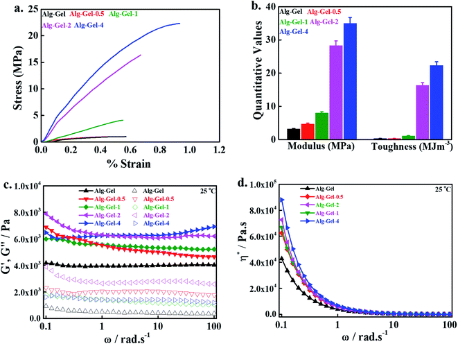 |
| | Fig. 3 Evaluation of the mechanical strength of the 3D-printed scaffolds, (a) stress–strain curve of the printed scaffolds (tensile mode), (b) the quantitative values of the modulus (MPa) and toughness (MJ m−3) of the printed scaffolds, (c) storage (G′, solid lines) and loss modulus (G′′, without lines) of the saturated swelled 3D-printed scaffolds, and (d) corresponding complex viscosity (η*) of the saturated swelled 3D-printed scaffolds at 25 °C. | |
The mechanical strength of the swelled scaffolds was evaluated using a rotational rheometer in the angular frequency (ω) range of 0.1–100 rad s−1 at 25 °C. Changes in the storage modulus (G′) and loss modulus (G′′) are given in Fig. 3c. An enhancement in G′ was observed in the composite scaffolds compared to the pure polymer scaffold throughout the measurement range, and composite scaffolds having 4% CNCs exhibited a greater G′ value in the higher region of ω than other scaffolds, indicating the positive influence of incorporated CNCs on the mechanical strength of the printed scaffolds. This enhancement in the mechanical strength of the composite scaffolds is attributed to the formation of a more interconnected polymeric network structure, which restricts the motion of the polymer chains, and consequently increases G′ values in the composite scaffolds relative to the pure polymer scaffolds.39 Nearly four-fold enhancement in G′ values occurred in the composite scaffolds compared to the pure polymer scaffolds. An enhancement in G′′ was also seen in the composite scaffolds compared to the pure polymer scaffold throughout the measurement range, and this value was further enhanced by increasing the amount of CNCs. However, G′′ values were less than the G′ values throughout the measurement range, showing the elasticity of the prepared hydrogel. Enhancement in the G′, G′′ values was also demonstrated earlier in CNC-based composite scaffolds relative to pure polymer scaffolds due to formation of a highly interconnected polymeric network structure in the composites.40 The viscosity complex (η*) value of the printed scaffolds within the measured ω ranges is given in Fig. 3d. The composite scaffolds exhibited greater η* values compared to pure polymer scaffolds in the lower regions of ω, and this property was further improved by increasing the amount of CNCs in the polymer matrix, indicating the shear thickening potential of the prepared hydrogel. A decrease in the η* values was noted in the higher region of measured ω, suggesting the shear-thinning potential of the prepared hydrogel. Shear thickening and thinning are essential properties for the printing of hydrogels.
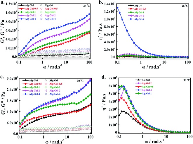
Additionally, we measured the mechanical strength of the developed hydrogels at different temperatures (25 and 30 °C) in the angular frequency (ω) ranges of 0.1–100 with a rotational rheometer; the changes in the G′, G′′ values at 25 °C are shown in Fig. 4a, and the corresponding η* values are shown in Fig. 4b. The developed hydrogels exhibited similar changing patterns of G′, G′′ and η* to the printed scaffolds, as mentioned above. However, the magnitudes of G′, G′′ and η* were higher in the hydrogels compared to the corresponding printed structures, showing more elasticity due to the interconnected polymeric network structure. Changes in the G′, G′′ values of the developed hydrogels in the measured ω regions at 30 °C are shown in Fig. 4c, and the corresponding η* changes are shown in Fig. 4d. Changes in G′, G′′ and η* patterns of the hydrogels at 30 °C were similar to those at 25 °C. However, their magnitudes were higher at 30 °C than at 25 °C. This might be due to the relaxation and motion of the polymer chains at a higher temperature, which facilitated a more cross-linked structure and increased the elasticity of the hydrogel. Improvement in the storage modulus of alginate/nanocellulose hydrogels was also previously reported with increasing temperatures.41 Changes in G′, G′′ and η* patterns of the hydrogels were also evaluated at 35 °C; these results are given in ESI Fig. 2.† Changes in G′, G′′ and η* were similar to the changes at 30 °C, indicating the formation of cross-linked polymeric network structures within the developed hydrogels.
 |
| | Fig. 4 Evaluation of the mechanical strength of the prepared hydrogels at different temperatures, (a) storage (G′, solid lines) and loss modulus (G′′, without lines), (b) corresponding complex viscosity (η*) of the hydrogels at 25 °C, (c) storage (G′, solid lines) and loss modulus (G′′, without lines), and (d) corresponding complex viscosity (η*) of the hydrogels at 30 °C. | |
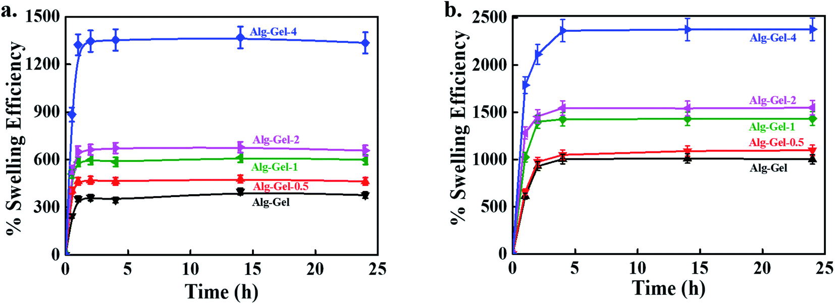
3.3. Swelling efficiency
The swelling potential of 3D-printed scaffolds was evaluated in distilled water at room temperature, and the results are shown in Fig. 5a. Swelling and mechanical stability are important features of scaffolds that determine their possible tissue engineering applications. The composite scaffolds exhibited better swelling efficiency than the pure polymer scaffolds, indicating the positive effects of CNCs on swelling behavior. Amorphous zones, availability of hydroxyl groups, crosslinking density, and crystallinity play crucial roles in swelling. The high swelling efficiency of the composite scaffolds is attributed to the presence of hydrophilic CNCs in the polymer matrix, which act as connecting agents between polymer chains, and consequently enhance their strength by effective stress transfer to absorb and maintain more water in their structure than in that of the pure polymer scaffold.42 The swelling efficiency of the 3D-printed scaffolds was also measured in PBS solution at room temperature, and the results are given in Fig. 5b. The swelling behavior of 3D-printed scaffolds in PBS was similar to that observed in aqueous medium. However, the swelling efficiency of the 3D-printed scaffolds was higher in the PBS solution than in the water medium. The printed scaffolds retained their structure in the PBS solution. These data indicate that it is possible to tune the scaffolds' swelling efficiency by incorporating a suitable amount of CNCs into the polymer matrix for the desired applications. However, no further enhancement in the swelling efficiency was observed in any scaffolds after 2 h of soaking, indicating that they had reached their equilibrium swelling state.
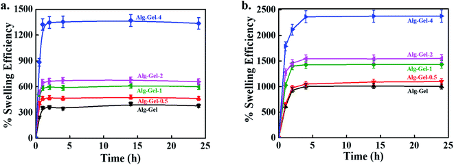 |
| | Fig. 5 The swelling potential of the 3D-printed scaffolds in, (a) water, and (b) PBS conditions at room temperature at indicated periods. | |
3.4. Biocompatibility and cell morphology
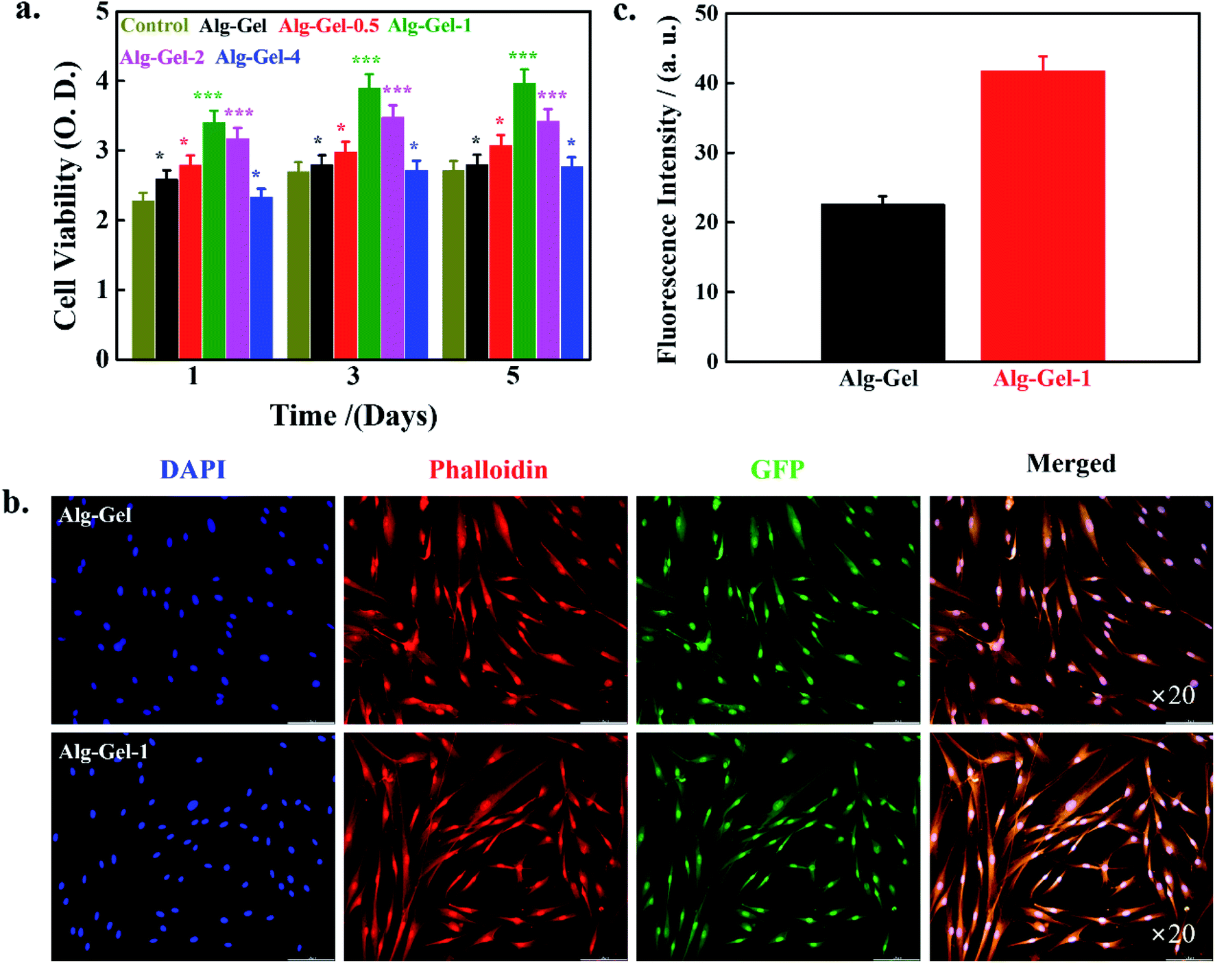
Biocompatibility is an important criterion for the materials, given their possible application as implants in tissue engineering and regenerative medicine.43 The biocompatibility of 3D-printed scaffolds was evaluated by WST-1 assay in the presence of hBMSCs after 1, 3, and 5 days of incubation, and the results are shown in Fig. 6a. Media without any scaffolds were used as controls. Notably, better cell viability occurred in the presence of the printed scaffold compared to the control, indicating biocompatibility. Moreover, the composite scaffolds demonstrated enhanced cell viability compared to the pure polymer scaffolds, indicating favorable effects of the incorporated CNCs. Cell viability is profoundly affected by the content of CNCs in the Alg–Gel matrix. Improved cell viability has occurred in the composite scaffold media compared to the pure polymer scaffold due to favorable topographical properties. It is well known that cell viability is strongly affected by topographical properties such as roughness, surface chemistry, and texture. Composite scaffolds showed a rougher surface morphology than the pure polymer scaffold; this roughness facilitated cellular activity by improving the exchange of nutrients and metabolic products. An enhancement in the cell proliferation of Saos2 cells was observed in wood-based CNFs incorporated with Alg–Gel scaffolds.16 Cell viability results of hBMSCs in the presence of different concentrations of CNCs (0.5, 1, 2, and 4%) at the indicated time points are given in ESI Fig. 3.† Media without CNC treatment were used as controls. Enhanced cell viability occurred in the presence of CNCs compared to the control, indicating CNC biocompatibility. Cell viability was significantly affected by CNC concentrations in the cultured media, and 1% CNCs showed greater cell viability than others, indicating that 1% CNCs is an optimum concentration for enhanced cellular activity. This decrease in cell viability at higher CNC levels may be attributed to the stiffness of the material and surface charge. Hosseinidoust et al. evaluated the effects of CNCs on the viability of different cell lines. They observed that cell viability was profoundly influenced by the surface charge of CNCs.44 Moreover, cell viability was further increased with increased culture time, indicating improved biocompatibility.
 |
| | Fig. 6 Evaluation of the biocompatibility of the 3D-printed scaffolds, (a) cell viability data of hBMSCs in the presence of the indicated scaffolds after different periods of treatment, (b) fluorescence microscopic images of hBMSCs, and (c) fluorescence intensity of hBMSCs in the presence of the indicated scaffolds after 5 days of treatment. | |
The morphology of hBMSCs in the presence of the indicated scaffolds after 5 days of treatment was examined using a fluorescence microscope, and morphologies are shown in Fig. 6b. Media with pure polymer scaffolds were considered as controls. Here, we used 1% CNC-incorporated composite scaffolds as the experimental groups because of their improved cell viability. The cells were healthy and adequately adhered to the scaffolds, exhibiting an elongated, flattened morphology and spreading across the entire surface of the scaffolds. Fluorescence intensity values are shown in Fig. 6c. The 1% CNC-incorporated scaffolds displayed greater values compared to the pure polymer scaffolds. Higher fluorescence intensity of hBMSCs in the presence of 1% CNC-incorporated scaffolds indicates better cellular activity.
3.5. Mineralization study
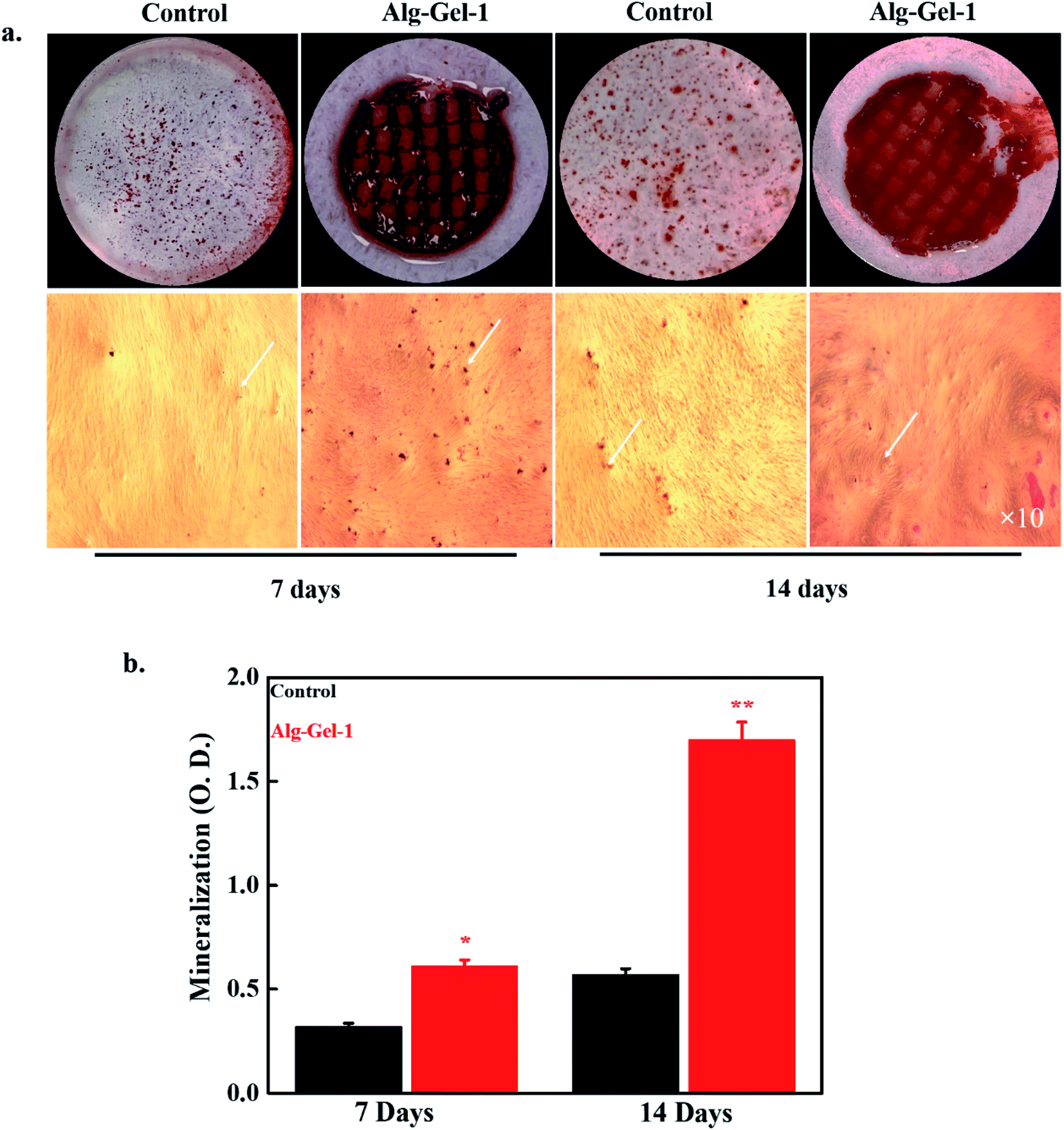
The mineralization potential of the 3D-printed scaffolds was evaluated by the ARS staining process in the presence of hBMSCs after 7 and 14 days of treatment. Images of the formed minerals are shown in Fig. 7a. Cultured media without any scaffolds were chosen as controls. Here, we used 1% CNC-incorporated composite scaffolds as the experimental groups because of their superior cellular activity. Composite scaffolds exhibited an intense red color compared to the control, indicating enhanced mineralization potential. Differentiation of stem cells into bone cells is the primary criterion for tissue engineering applications. Bone regeneration is a complicated biological process, with expression of various osteogenic-related gene markers occurring during differentiation.45 The quantitative values of the formed mineral in the presence of fabricated scaffolds or control after 7 and 14 days of treatment are shown in Fig. 7b. The 1% CNC-incorporated composite scaffolds exhibited greater mineralization potential than the control after 7 days of treatment, which further increased after 14 days of treatment, showing improved composite mineralization efficiency. For bone tissue repair and regeneration applications, the scaffolds should adequately adhere to the implanted tissue and facilitate mineralization. The mineralization potential of the scaffolds is profoundly affected by their surface topography, availability of active functional groups, and interaction with tissue.46 The mineralization potential of CNCs was also evaluated by the ARS technique in the presence of hBMSCs after 7 and 14 days of treatment; images of the formed minerals are shown in ESI Fig. 4.† Media without CNCs were used as controls. A more intense color was observed in the CNC-treated media than in the control, indicating improved CNC mineralization potential. Among these CNC concentrations (0.5, 1, 2, and 4%), 1% CNCs exhibited a more intense color, suggesting that 1% is the optimum concentration for enhanced mineralization. The availability of active hydroxyl (–OH) groups and the rough surface morphology of the composite scaffolds facilitated the enhanced cellular activity and consequently improved mineralization compared to the control. This finding indicates that the fabricated scaffolds could be used as a biomaterial in bone tissue engineering.
 |
| | Fig. 7 Evaluation of the mineralization potential of the 3D-printed scaffold in the presence of hBMSCs, (a) the mineralized nodule formation by the alizarin red-S staining process along with corresponding optical images for nodule formation after indicated periods of treatment (arrow indicates the formed nodules), and (b) the quantitative values of the formed mineral. The media without any samples were considered as control. | |
3.6. ALP activity and gene expression
Alkaline phosphatase (ALP) is one of the most important osteogenic gene markers and is expressed during early osteogenesis. ALP expression in hBMSCs in the presence of the fabricated scaffolds after 7 and 14 days of treatment is shown in Fig. 8a. Here, we chose 1% CNC-incorporated composite scaffold as an experimental material because of its better mineralization potential. Untreated media were used as controls. Notably, better ALP activity was observed in Alg–Gel-1 treated media compared to the control, showing osteogenic potential in the treatment group. Improved ALP activity was previously reported in wood-based CNFs and bioactive glass-modified gelatin–alginate printed scaffolds.16 Quantitative values of ALP are shown in Fig. 8b. Various genes such as runt-related transcription factor (Runx2), ALP, bone sialoprotein (BSP), and osteopontin (OPN) are expressed during osteogenesis. The expression of these gene markers in hBMSCs in the presence of the fabricated scaffolds was measured by qPCR after 7 and 14 days of treatment, and the results are shown in Fig. 8c. Enhanced expression of these genes was observed in the scaffold-treated media relative to the control. Runx2 is considered an early gene marker in osteogenesis, and osteoblast differentiation does not occur without Runx2. Runx2 expression was higher in the scaffold-treated media than in the control. Upregulation of the OPN gene occurred in the scaffolds treated with media compared to control, suggesting the scaffolds' osteogenic potential. These results indicate that Alg–Gel-1 scaffolds have the potential to stimulate osteogenic differentiation by elevating the expression of differentiation-specific gene markers.45
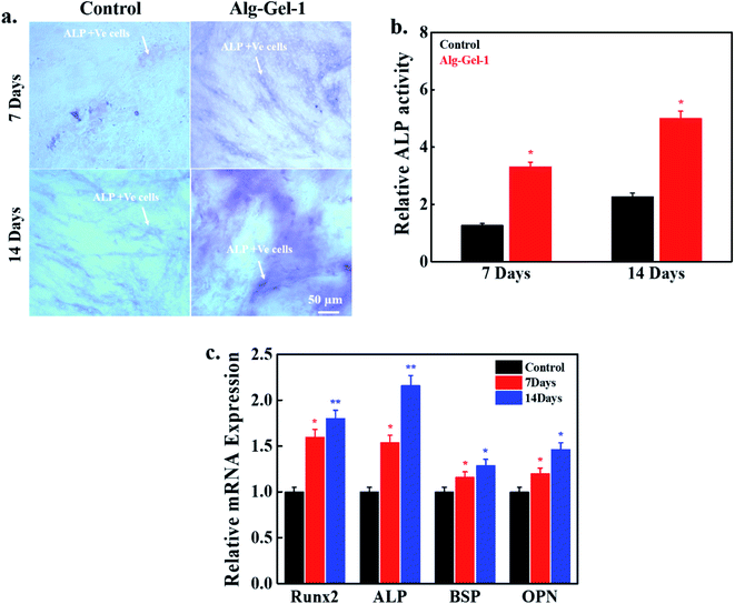 |
| | Fig. 8 Evaluation of the alkaline phosphatase (ALP) activity and osteogenic genes expression potential in BMSCs with or without Alg–Gel-1 scaffolds, (a) the photographs of the ALP stained plates (white arrows indicate the presence of ALP +ve cells), (b) the corresponding quantitative values of ALP activity at indicated time intervals with or without scaffolds, and (c) osteogenic genes expression potential of the printed Alg–Gel-1 composite scaffolds at indicated time intervals. The media without any scaffolds were taken as control. | |
4. Conclusions
In this study, we fabricated and characterized a 3D-printable cellulose nanocrystals-based hydrogel for tissue engineering applications. The interaction between the polymer matrix and incorporated CNCs was monitored by FTIR spectroscopy. A greater interaction was observed between the polymer chains and CNCs than in controls. No significant change in the cell morphology was observed for the printed scaffolds after freeze-drying. Composite scaffolds exhibited a rough surface morphology compared to pure polymer scaffolds. Notably, better cell viability was observed in hBMSCs in the presence of the composite scaffolds. Moreover, cellular activity was profoundly affected by CNC content in the prepared hydrogels. The cells showed an elongated and flattened morphology, and the fluorescence intensity was higher in the composite scaffolds-treated media than in the control. Furthermore, enhanced mineralization was observed in the presence of the composite scaffolds-treated media compared to the control, indicating better composite mineralization potential. Enhanced expression of osteogenic related genes occurred in the scaffold-treated media compared to the control, showing improved osteogenic potential in the presence of scaffolds. Based on these results, we conclude that the fabricated composite scaffold is an attractive biomaterial for tissue engineering applications, especially bone tissue. However, more detailed experiments are needed to explore the potential of the prepared biomaterial for tissue engineering.
Conflicts of interest
There are no conflicts to declare.
Acknowledgements
This research was supported by the ‘Basic Research Program’ through the ‘National Research Foundation of Korea (NRF)’ funded by the ‘Ministry of Education’ (NRF-2018R1A6A1A03025582) and the ‘National Research Foundation of Korea’ (NRF-2019R1D1A3A03103828).
References
- Y. Xia, F. Mei, Y. Duan, Y. Gao, Z. Xiong, T. Zhang and H. Zhang, J. Biomed. Mater. Res., Part A, 2012, 100, 1044–1050 CrossRef.
- S. Pina, J. M. Oliveira and R. L. Reis, Adv. Mater., 2015, 27, 1143–1169 CrossRef CAS.
- B. Guo and P. X. Ma, Biomacromolecules, 2018, 19, 1764–1782 CrossRef CAS.
- K. Wang, K. Nune and R. Misra, Acta Biomater., 2016, 36, 143–151 CrossRef CAS.
- A. M. Martins, C. M. Alves, F. K. Kasper, A. G. Mikos and R. L. Reis, J. Mater. Chem., 2010, 20, 1638–1645 RSC.
- B. Lei, B. Guo, K. J. Rambhia and P. X. Ma, Front. Med., 2019, 13, 189–201 CrossRef.
- J. A. Rowley, G. Madlambayan and D. J. Mooney, Biomaterials, 1999, 20, 45–53 CrossRef CAS.
- C. Azuma, K. Yasuda, Y. Tanabe, H. Taniguro, F. Kanaya, A. Nakayama, Y. M. Chen, J. P. Gong and Y. Osada, J. Biomed. Mater. Res., Part A, 2007, 81, 373–380 CrossRef.
- S. Van Vlierberghe, P. Dubruel and E. Schacht, Biomacromolecules, 2011, 12, 1387–1408 CrossRef CAS.
- K. Yue, G. Trujillo-de Santiago, M. M. Alvarez, A. Tamayol, N. Annabi and A. Khademhosseini, Biomaterials, 2015, 73, 254–271 CrossRef CAS.
- M. E. Klontzas, H. Drissi and A. Mantalaris, Alginates, IntechOpen, 2019, DOI:10.5772/intechopen.88020.
- U. Rottensteiner, B. Sarker, D. Heusinger, D. Dafinova, S. Rath, J. Beier, U. Kneser, R. Horch, R. Detsch and A. Boccaccini, Materials, 2014, 7, 1957–1974 CrossRef CAS.
- K. Y. Lee and D. J. Mooney, Prog. Polym. Sci., 2012, 37, 106–126 CrossRef CAS.
- G. D. Nicodemus and S. J. Bryant, Tissue Eng., Part B, 2008, 14, 149–165 CrossRef CAS.
- K. C. Kolan, J. A. Semon, B. Bromet, D. E. Day and M. C. Leu, Int. J. Bioprint., 2019, 5, 204 Search PubMed.
- M. Ojansivu, A. Rashad, A. Ahlinder, J. Massera, A. Mishra, K. Syverud, A. Finne-Wistrand, S. Miettinen and K. Mustafa, Biofabrication, 2019, 11, 035010 CrossRef CAS.
- T. A. Mir and M. Nakamura, Tissue Eng., Part B, 2017, 23, 245–256 CrossRef.
- M. Arbatti, X. Shan and Z. Y. Cheng, Adv. Mater., 2007, 19, 1369–1372 CrossRef CAS.
- S. Saint, J. G. Elmore, S. D. Sullivan, S. S. Emerson and T. D. Koepsell, Am. J. Med., 1998, 105, 236–241 CrossRef CAS.
- X. Wang, Y. Hu, L. Song, H. Yang, W. Xing and H. Lu, J. Mater. Chem., 2011, 21, 4222 RSC.
- D. K. Patel, S. D. Dutta and K.-T. Lim, RSC Adv., 2019, 9, 19143–19162 RSC.
- S. D. Dutta, D. K. Patel and K.-T. Lim, J. Biol. Eng., 2019, 13, 55 Search PubMed.
- S. D. Dutta, D. K. Patel, Y.-R. Seo, C.-W. Park, S.-H. Lee, J.-W. Kim, J. Kim, H. Seonwoo and K.-T. Lim, J. Nanomater., 2019, 2019, 1–11 Search PubMed.
- N. Lin and A. Dufresne, Eur. Polym. J., 2014, 59, 302–325 CrossRef CAS.
- B. S. L. Brito, F. V. Pereira, J.-L. Putaux and B. Jean, Cellulose, 2012, 19, 1527–1536 CrossRef CAS.
- M. Osorio, A. Cañas, J. Puerta, L. Díaz, T. Naranjo, I. Ortiz and C. Castro, Sci. Rep., 2019, 9, 1–14 CrossRef CAS.
- L. Van Hai, H. N. Son and Y. B. Seo, Cellulose, 2015, 22, 1789–1798 CrossRef CAS.
- J. M. Dugan, J. E. Gough and S. J. Eichhorn, Biomacromolecules, 2010, 11, 2498–2504 CrossRef CAS.
- S. Sultan and A. P. Mathew, Nanoscale, 2018, 10, 4421–4431 RSC.
- D. K. Patel, S. D. Dutta, J. Hexiu, K. Ganguly and K. T. Lim, Int. J. Biol. Macromol., 2020, 162, 1429–1441 CrossRef CAS.
- D. K. Patel, S. D. Dutta, K. Ganguly and K.-T. Lim, Int. J. Biol. Macromol., 2021, 170, 178–188 CrossRef CAS.
- M. Saravanan and K. P. Rao, Carbohydr. Polym., 2010, 80, 808–816 CrossRef CAS.
- M. E. Badawy, N. E. Taktak, O. M. Awad, S. A. Elfiki and N. E. A. El-Ela, J. Macromol. Sci., Part B: Phys., 2017, 56, 359–372 CrossRef CAS.
- A. Kumar, Y. Lee, D. Kim, K. M. Rao, J. Kim, S. Park, A. Haider, D. H. Lee and S. S. Han, Int. J. Biol. Macromol., 2017, 95, 962–973 CrossRef CAS.
- T. Schmid, A. Messmer, B.-S. Yeo, W. Zhang and R. Zenobi, Anal. Bioanal. Chem., 2008, 391, 1907–1916 CrossRef CAS.
- F. You, X. Wu and X. Chen, Int. J. Polym. Mater. Polym. Biomater., 2017, 66, 299–306 CrossRef CAS.
- D. K. Patel, D. Rana, V. K. Aswal, S. Srivastava, P. Roy and P. Maiti, Polymer, 2015, 65, 183–192 CrossRef CAS.
- N. Naseri, B. Deepa, A. P. Mathew, K. Oksman and L. Girandon, Biomacromolecules, 2016, 17, 3714–3723 CrossRef CAS.
- S. D. Dutta, J. Hexiu, D. K. Patel, K. Ganguly and K.-T. Lim, Int. J. Biol. Macromol., 2021, 167, 644–658 CrossRef CAS.
- X. Yang, E. Bakaic, T. Hoare and E. D. Cranston, Biomacromolecules, 2013, 14, 4447–4455 CrossRef CAS.
- P. Siqueira, É. Siqueira, A. E. De Lima, G. Siqueira, A. D. Pinzón-Garcia, A. P. Lopes, M. E. C. Segura, A. Isaac, F. V. Pereira and V. R. Botaro, Nanomaterials, 2019, 9, 78 CrossRef.
- T. I. Shaheen, A. S. Montaser and S. M. Li, Int. J. Biol. Macromol., 2019, 121, 814–821 CrossRef CAS.
- D. K. Patel, S. Senapati, P. Mourya, M. M. Singh, V. K. Aswal, B. Ray and P. Maiti, ACS Biomater. Sci. Eng., 2017, 3, 3351–3363 CrossRef CAS.
- Z. Hosseinidoust, M. N. Alam, G. Sim, N. Tufenkji and T. G. M. van de Ven, Nanoscale, 2015, 7, 16647–16657 RSC.
- H.-B. Kim, B. Jin, D. K. Patel, J.-W. Kim, J. Kim, H. Seonwoo and K.-T. Lim, IEEE Trans. Nanobioscience, 2019, 18, 463–468 Search PubMed.
- S. Gorgieva, L. Girandon and V. Kokol, Mater. Sci. Eng., C, 2017, 73, 478–489 CrossRef CAS.
Footnotes |
| † Electronic supplementary information (ESI) available. See DOI: 10.1039/d0ra09620b |
| ‡ These authors contributed equally to this work. |
|
| This journal is © The Royal Society of Chemistry 2021 |
Click here to see how this site uses Cookies. View our privacy policy here. 
 Open Access Article
 This Open Access Article is licensed under a Creative Commons Attribution-Non Commercial 3.0 Unported Licence
 *
*