
 Open Access Article
 This Open Access Article is licensed under a Creative Commons Attribution-Non Commercial 3.0 Unported Licence
Highly efficient In2S3/WO3 photocatalysts: Z-scheme photocatalytic mechanism for enhanced photocatalytic water pollutant degradation under visible light irradiation†
Qingqing Qiu a,
Peng Zhua,
Yao Liub,
Tongxiang Liang*a,
Tengfeng Xie*c and
Yanhong Linc
a,
Peng Zhua,
Yao Liub,
Tongxiang Liang*a,
Tengfeng Xie*c and
Yanhong Linc
aCollege of Rare Earths, Jiangxi University of Science and Technology, Ganzhou 341000, P. R. China
bFaculty of Materials Metallurgy and Chemistry, Jiangxi University of Science and Technology, Ganzhou 341000, P. R. China
cCollege of Chemistry, Jilin University, Changchun 130012, P. R. China
First published on 18th January 2021
Abstract
A Z-scheme system In2S3/WO3 heterojunction was fabricated via a mild hydrothermal method and further applied for photocatalytic degradation of tetracycline (TCH) and Rhodamine B (Rh B) under visible light irradiation. The morphological structure, chemical composition and optical properties were studied by XRD, SEM, HRTEM and UV-visible absorption spectra. The results revealed that In2S3/WO3 hierarchical structures were successfully constructed, and the prepared In2S3/WO3 photocatalysts exhibited enhanced visible-light absorption compared to pure WO3 nanorods, which are essential to improve the photocatalytic performance. The degradation rate of TCH using the In2S3(40 wt%)/WO3 heterostructure (WI40) photocatalyst was about 212 times and 22 times as high as that for pure WO3 and pure In2S3, respectively. The degradation rate of Rh B with the WI40 photocatalyst was about 56 times the efficiency of pure WO3 and 7.6 times that of pure In2S3. The results of the surface photovoltage (SPV), transient photovoltage (TPV) and reactive oxidation species (ROS) scavenger experiments indicated that the Z-scheme system of In2S3/WO3 is favorable for photoexcited charge transfer at the contact interface of In2S3 and WO3, which benefits the charge separation efficiency and depresses the recombination of photoexcited charge, resulting in favorable photocatalytic pollutant degradation efficiency under visible light irradiation.
1 Introduction
In the past few decades, water pollutants have seriously threatened human health due to rapidly developing industries.1–5 Various techniques for purifying the environment have been investigated. Among these techniques, photocatalytic degradation technology has captured much attention as a new environment-purifying technique because of its low toxicity, low cost and easy recovery.6–8 However, the performance of most photocatalysts is seriously restricted by the range of sunlight utilization and the photoexcited charge separation efficiency.9Recent studies suggest that an excellent catalytic system should meet three conditions: the high utilization of sunlight, strong oxidation–reduction properties and high separation efficiency of photoexcited charge.10–13 Obviously, it is difficult to have high catalytic activity for a mono-component semiconductor photocatalyst. In this regard, construction of heterojunction structures is an effective method to boost the photocatalytic performance.14 The traditional type II heterojunction structures can achieve a band structure with adjustable and high separation efficiency of photogenerated charge.15 However, the type II heterojunction structures lead to photoexcited electron transfer to the conduction band with lower position, then the photoexcited holes transfer to the valence band with a higher position, which is a disadvantage for the photocatalytic oxidation–reduction properties of photoexcited charge.10,15 Thus, the design and construction of novel heterojunction structures seem inevitable. The design of Z-scheme heterojunction structures instantly became the focus of photocatalytic studies, and is considered to be the most promising strategy to solve the issues above.15,16
To date, many studies about Z-scheme heterojunction structures have been reported, such as g-C3N4/WO3, CdS/Au/TO2, CdS/Au/WO3, MnxCd1−xS/WO3, ZnO/Au/SnO2, CeO2/Ag/AgBr, WO3/Au/In2S3, CdS/Au/BiVO4 and BiOI/Pt/g-C3N4.17–25 In most cases of the Z-scheme heterojunction catalytic system, however, noble metals are used as the electron mediator, such as Pt, Au and Ag, which can increase the cost of preparation and application.26 Thus, it is necessary to construct direct Z-scheme heterojunction structures.
Indium sulfide (In2S3), with a bandgap of 2.2 eV, is an effective visible-light-driven photocatalyst that has been extensively used in the field of photocatalysis due to its narrow bandgap, good chemical stability and low toxicity.27–30 Besides these, the energy structure of In2S3 semiconductor has excellent reduction performance due to its conduction band with a higher position. But the In2S3 crystal has poor crystallinity and too rapid rate of charge recombination, which leads to undesirable photocatalytic degradation activity.29,30 WO3 semiconductor has high carrier mobility, good crystallinity, good chemical stability, thermal stability and excellent antioxidant properties due to its valence band with lower position compared to other semiconductor materials, but has a wide bandgap and the limitation of visible-light utilization.31–33 Thus, we exploit a suitable preparation method to prepare In2S3/WO3 composite, which can expand visible light utilization and improve the photoexcited charge separation efficiency. Besides, we also noticed that the Z-scheme system WO3/Au/In2S3 was used in the photocatalytic reduction of CO2.24 The report suggested that the Z-scheme In2S3/WO3 heterostructure can form and accelerate the rate of charge carrier separation. However, there are few reports on the application and photocatalytic mechanism of all-solid-state Z-scheme In2S3/WO3 heterostructure in photocatalytic degradation.
Based on the above discussion, we focus on the construction of a direct Z-scheme In2S3/WO3 heterostructure through a simple and facile method. The degradation efficiency of the all-solid-state In2S3/WO3 photocatalyst was much higher than that of the pristine In2S3 and WO3. The photoexcited charge behavior of the Z-scheme In2S3/WO3 heterostructure was studied using the SPV and TPV techniques. Furthermore, reactive oxidation species (ROS) scavenger experiments confirmed that the Z-scheme In2S3/WO3 structure induces electrons in In2S3 and holes in WO3 with an unobstructed charge transfer route, effectively improving the separation efficiency of photoexcited charge.
2 Experimental details
2.1. Preparation of WO3 nanorods
The WO3 nanorods were prepared using a simple hydrothermal method according to the previous reports.26,31 In a typical experiment, 2.0 g of sodium tungstate hydrate and 0.6 g of sodium chloride in 60 mL distilled water was stirred for 6 h at room temperature. Afterwards, concentrated hydrochloric acid was added dropwise until the pH of solution reached 2.0, and the solution was kept stirring for 3 h. The resulting solution was transferred to a 100 mL Teflon-lined stainless steel autoclave and heated at 180 °C for 24 h. Finally, the obtained WO3 nanorods were centrifuged and washed with distilled water and ethanol, and then the precipitates were dried at 50 °C for 12 h under vacuum condition.2.2. Preparation of the Z-scheme In2S3/WO3 photocatalyst
The Z-scheme In2S3/WO3 photocatalyst was prepared by a simple and facile hydrothermal method. First, 0.3 g of WO3 was ultrasonically dispersed in 30 mL distilled water. A certain amount of indium trichloride hydrate was dissolved in the WO3 suspension, then a certain amount of sodium sulfide hydrate was added dropwise. After vigorous stirring for 5 h, the mixture was transferred to a 100 mL Teflon-lined stainless steel autoclave and heated at 180 °C for 12 h. Finally, the obtained precipitate was centrifuged and washed with distilled water and ethanol, and the precipitates were dried at 50 °C for 12 h under vacuum condition. The mass ratios of In2S3 to WO3 were R = 0, 20, 30, 40 and 50, which were marked as WI0, WI20, WI30, WI40 and WI50, respectively. The pure In2S3 powder sample was prepared under the same conditions without WO3 powder.2.3. Characterization and measurements
The surface morphology of the obtained powder samples was examined by the MLA 650F field emission scanning electron microscope (SEM, Navo NanoSEM FEI). X-ray diffraction (XRD) was carried out to study the crystal structure of the samples using an X-ray diffractometer with Cu Kα radiation (Empyrean, PANalytical B.V.; λ = 1.54 Å) in the range of 10–70° (2θ). The absorption spectra were measured with a UV-vis spectrophotometer (UV3600, Shimadzu).Surface photovoltage (SPV) spectra were obtained using a lock-in-based surface photovoltage (SPV) measurement system with a grating monochromator (Omni-λ5007, Zolix), a lock-in amplifier (model SR830-DSP), and an optical chopper (model SR540) running at a frequency of 24 Hz.34 Transient photovoltage (TPV) measurements were carried out using a self-assembled instrument with a Nd:YAG laser (Q-smart 450, Quantl, Inc.).34,35 The intensity of the pulse was regulated with a neutral gray filter and a Joule meter (Starlite, Ophir, Inc.). The transient signal was recorded using a 500 MHz digital phosphor oscilloscope (TDS 5054, Tektronix). Both the SPV and TPV measurements were performed in ambient air.
2.4. Photocatalytic degradation experiments
In a typical photocatalytic degradation experiment, 50 mg of photocatalyst was mixed with 100 mL of tetracycline hydrochloride aqueous solution (TCH, 30 mg L−1) (pH = 4.5) or Rhodamine B aqueous solution (Rh B, 35 mg L−1) (pH = 6.0), then ultrasonically dispersed for 5 min. The obtained mixed solution was vigorously stirred for 30 min in the dark to achieve the absorption–desorption equilibrium. In order to investigate the water pollutant degradation efficiency, 1 mL of the mixture was taken out after a given time interval and centrifuged for 10 min to achieve the purpose of solid–liquid separation after visible light irradiation (λ > 420 nm). The concentration of TCH and Rh B was measured with the absorption wavelength of 357 nm and 554 nm, respectively, using a UV-vis spectrometer (UV 2400).Scavenger tests for reactive oxidation species (ROSs) were carried out under the same experimental conditions except for the addition of scavengers for the degradation process. Potassium bromate (KBrO3, 10 mM), sodium oxalate (Na2C2O4, 10 mM), 2,2,6,6-tetramethylpiperidine-1-oxyl (TEMPOL, 10 mM) and isopropanol (10 mM) were used as e−, h+, ˙O2− and ˙OH scavengers, respectively.
3 Results and discussion
3.1. Structural characterization of photocatalysts
Fig. 1 shows the X-ray diffraction (XRD) patterns of WI0, WI50 and In2S3 samples. The crystal structure of pure WO3 is hexagonal phase (JCPDS card no. 75-2187), as shown in Fig. 1(a).26–31 The crystal structure of pure In2S3 is cubic phase (JCPDS card no. 32-0456), as shown in Fig. 1(b).7,28 Fig. 1(a) shows that only the hexagonal structure WO3 is observed, and no obvious diffraction peak is observed for the WI50 sample. This may be attributed to the diffraction peak of In2S3 sample being too weak compared to the diffraction peak of WO3. In addition, the intensity of diffraction peak for the WI20, WI30, WI40 and WI50 samples is weakened compared to that for the pure WO3, which shows that the preparation of In2S3/WO3 composites makes the crystallinity poorer (see Fig. S1†). With the increase of In2S3 loading, the intensity of diffraction peak becomes slightly weaker due to the reduced WO3 content.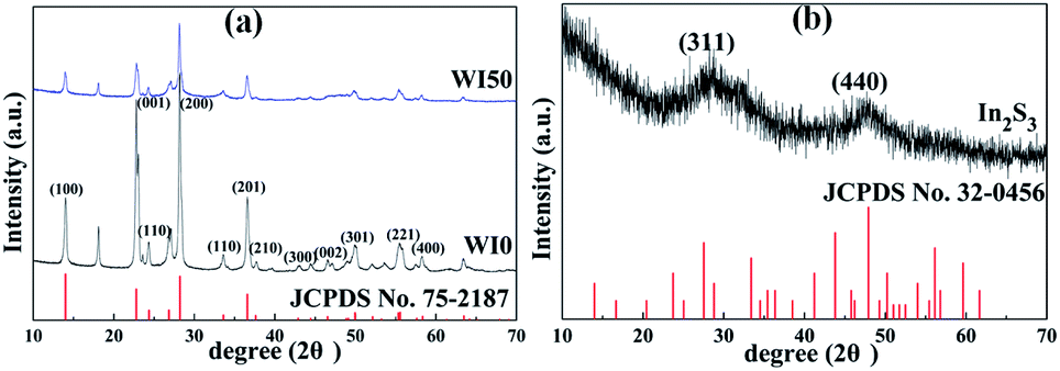 | ||
| Fig. 1 XRD patterns of (a) WI0, WI50 and (b) In2S3. | ||
The morphology of pure WO3, In2S3, In2S3 (20 wt%)/WO3 and In2S3 (40 wt%)/WO3 samples was determined by FESEM (Fig. 2). It can be seen from Fig. 2(a) that the pure WO3 consists of nanorods and bulk nanomaterials. The length of nanomaterials is about 0.1–1.1 μm, and the width is about 100–350 nm. Tiny nanoparticles with diameters of 10–110 nm can be observed on the surface of nanorods and bulk nanomaterials. The surface of the nanorods is smooth for pure WO3 (see Fig. 2(b)). As shown in Fig. 2(c), In2S3 nanoparticles with diameters of 100–720 nm were obtained. However, the surface of the nanorods becomes rough with the loading of In2S3 (see Fig. 2(d)). Fig. 2(e) shows that the nanoparticles increase significantly for WI40 composite, which proves that the In2S3 nanoparticles are loaded on the WO3 nanorods and bulk nanomaterials. In Fig. 2(f), the EDX of WI40 illustrates that the WI40 composite consists of O, W, S and In atoms. Therefore, the above analyses indicate the In2S3 is deposited on the WO3 successfully. The EDX mapping images obtained using TEM-EDX spectroscopy are shown in Fig. S2, S3† and 3. Fig. S2 and S3† show that only the elements W and O for pure WO3, and the elements In and S for pure In2S3 are detected. Fig. 3 shows the presence of W, O, In and S for WI40. The results illustrate all the elements are well distributed.
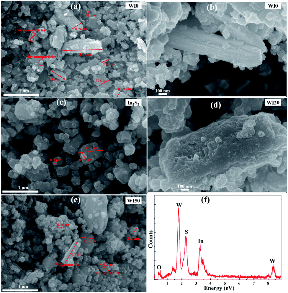 | ||
| Fig. 2 FESEM images of (a and b) WI0, (c) In2S3, (d) WI20, (e) WI50; (f) energy-dispersive X-ray spectroscopy (EDX) of WI40. | ||
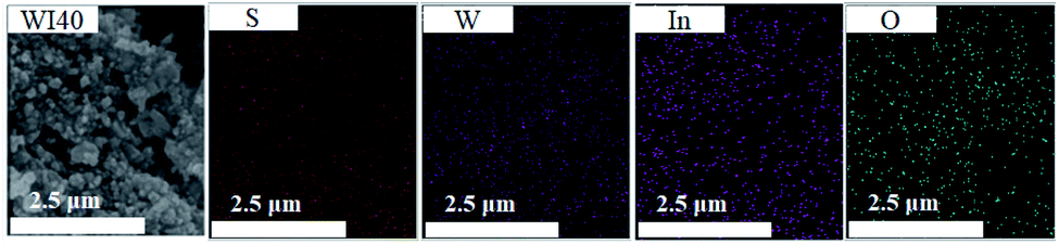 | ||
| Fig. 3 EDX mappings of WI40. | ||
Fig. 4 shows the transition electron microscopy (TEM) and high-magnification transition electron microscopy (HRTEM) images of WO3, In2S3 and WI40. Fig. 4(a) shows that the pure WO3 is made up of nanorods, bulk nanomaterials and tiny nanoparticles, corresponding to the SEM images of WO3. The lattice spacing of WO3 in the (200) plane is 0.316 nm (see Fig. 4(b)). Fig. 4(c) shows that pure In2S3 is made up of nanoparticles, and the lattice spacing of In2S3 in the (311) plane is 0.324 nm (see Fig. 4(d)). As shown in Fig. 4(e), the In2S3 nanoparticles closely connect with WO3 nanomaterials. The HRTEM in Fig. 4(f) shows the In2S3/WO3 heterojunction is formed between In2S3 and WO3. One can see in Fig. 4(f) that the lattice spacing of 0.316 nm is ascribed to the (200) plane of WO3, while the lattice spacing of 0.324 nm is ascribed to the (211) plane of In2S3. The results confirm that WO3 and In2S3 are in close contact with each other, clearly indicating growth of the In2S3/WO3 hierarchical structures.
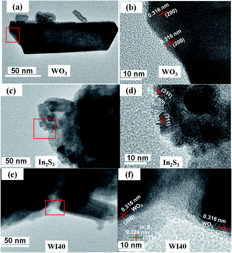 | ||
| Fig. 4 (a) TEM image of WO3 and (b) HRTEM image of WO3; (c) TEM image of In2S3 and (d) HRTEM image of In2S3; (e) TEM image of WI40 and (f) HRTEM image of WO3 and In2S3. | ||
In addition, we then performed the selected area electron diffraction (SAED) pattern of WI40 to examine the In2S3/WO3 hierarchical structures for more detailed information. Fig. 5 indicates that the lattice spacing of 0.247 nm and 0.179 nm correspond to the values of the (311) lattice plane of hexagonal phase WO3 (JCPDS card no. 75-2187), and the observed 0.247 nm and 0.179 nm lattice spacing can be assigned to the (600) and (311) planes of cubic phase In2S3 (JCPDS card no. 32-0456). The results further indicate that the In2S3/WO3 hierarchical structures were successfully constructed.
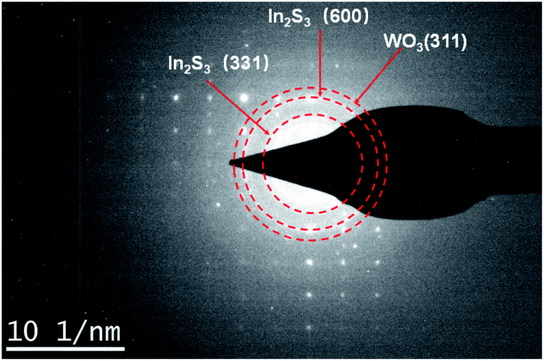 | ||
| Fig. 5 SAED pattern of WI40. | ||
The absorption spectra of WI0, WI40 and In2S3 samples are shown in Fig. 6. The absorption band edge of pure WO3 is about 435 nm, and that of pure In2S3 is about 540 nm. In addition, the absorption band edge of In2S3/WO3 composites exhibits a red shift with the increase of In2S3 loading. The bandgap energy of the semiconductor is calculated by the following formula:31
| (αhν) = A(hν − Eg)n/2, |
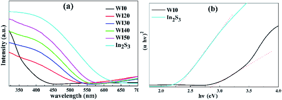 | ||
| Fig. 6 (a) UV-visible absorption spectra of WI0, WI20, WI30, WI40, WI50 and In2S3. (b) Plots of the (αhν)2 versus photon energy (hν) for In2S3 and WI0. | ||
3.2. Photocatalytic performance of photocatalysts
The degradation of Rhodamine B (Rh B) under visible light irradiation (λ > 420 nm) was investigated in order to estimate the photocatalytic performance of the prepared photocatalysts. As shown in Fig. 7(a), the Rh B degradation efficiency of 11% was obtained for pure WO3 after 20 min of irradiation with visible light, and the Rh B degradation efficiency of 56.54% was obtained for pure In2S3 under the same condition. However, Fig. 7(a) shows that the In2S3/WO3 composites display apparently superior Rh B degradation activity. The degradation efficiencies of Rh B are 82.2%, 96.0%, 97.8%, and 96.9% for WI20, WI30, WI40, and WI50 composites, respectively, after 20 min of irradiation. Fig. S4(a)† shows the UV-visible absorption spectra of Rh B solutions before and after photocatalytic degradation reaction in the presence of WI40. The WI40 photocatalyst shows an obvious and significant degradation effect, and Rh B is almost completely degraded after 20 min of irradiation with visible light.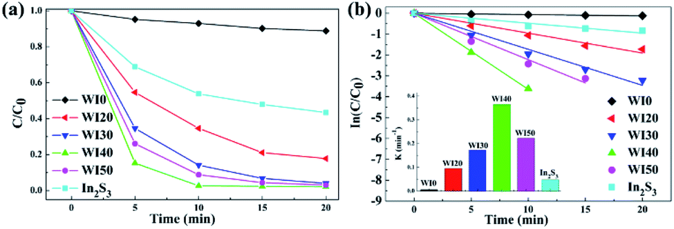 | ||
| Fig. 7 (a) Photocatalytic degradation performance of WI0, WI20, WI30, WI40, WI50 and In2S3 for Rh B under visible light irradiation; (b) corresponding plots of ln(C0/C) versus irradiation time t and the calculated rate constant k. | ||
In order to quantitatively evaluate the reaction kinetics of Rh B degradation, the experimental data in Fig. 7(a) could be fitted by the Langmuir–Hinshelwood model and expressed by the following equation:36
| ln(C0/C) = kappt, |
The degradation efficiency of tetracycline hydrochloride (TCH) under visible light irradiation was studied to further investigate the effect of the interaction between WO3 and In2S3. As shown in Fig. 8(a), the degradation efficiencies of TCH for pure WO3 and In2S3 are 7.1% and 56.6%, respectively, after 150 min of irradiation. However, the degradation efficiencies of TCH are 51.6%, 62.5%, 84.7%, and 81.4% for WI20, WI30, WI40, and WI50 composites after 150 min of irradiation. The corresponding curves of ln(C0/C) versus irradiation time t and the degradation rate constant k were also calculated, as shown in Fig. 8(b). The degradation rate constants (k) of TCH are 0.0004, 0.0036, 0.0039, 0.0085, 0.0074 and 0.0038 min−1 for WI0, WI20, WI30, WI40, WI50 and In2S3, respectively. The TCH degradation rate constants for WI40 are about 212 times and 22 times as high as that for pure WO3 and pure In2S3, respectively, illustrating that the WI40 composite photocatalyst is apparently superior to pure WO3 and In2S3. Moreover, the UV-visible absorption spectra of TCH solutions before and after photocatalytic degradation reaction in the presence of WI40 was recorded, as shown in Fig. S4(b).† Significantly, the WI40 photocatalyst exhibits effective degradation of the TCH pollutant, and the degradation efficiency for TCH is close to 90% under visible light irradiation. However, WI40 shows relatively low photocatalytic performance for TCH degradation compared with the latest works (Table 2), which suggests that the prepared photocatalyst is more suitable for Rh B degradation. The above results indicate that the synergistic effect between WO3 and In2S3 plays a crucial role for the degradation of these water pollutants.
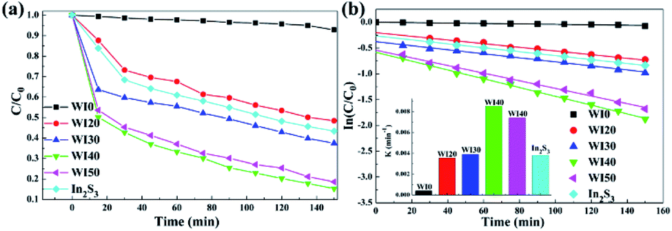 | ||
| Fig. 8 (a) Photocatalytic degradation performance of WI0, WI20, WI30, WI40, WI50 and In2S3 for TCH under visible light irradiation; (b) corresponding plots of ln(C0/C) versus irradiation time t and the calculated rate constant k. | ||
The degradation of Rh B and TCH might be affected under different solution pH conditions.17 The degradation experiments were carried out at different pH values, as shown in Fig. S5.† The result indicates that the alkaline solution has remarkable impact on the degradation efficiency of Rh B, where neutral and acidic solutions only have a mild effect on the degradation efficiency; 97.89%, 96.79%, 98.23% and 90.57% of Rh B were removed at pH values of 2, 4, 7 and 10, respectively. However, the initial pH only has slight impact on the photoactivity for TCH degradation, and 82.28%, 84.94%, 86.47% and 85.23% of TCH were removed at pH values of 2, 5, 7 and 9. This gives evidence that the In2S3/WO3 photocatalyst maintains a relatively high photocatalytic performance over a wide pH range. To investigate further, a physical mixture of pure WO3 and In2S3 with the same mass ratio (40%) was used as the control during photocatalytic degradation, as shown in Fig. S6.† Obviously, the degradation performance of WI40 is better, compared to that of the physical mixture of In2S3(40 wt%)/WO3 for Rh B and TCH degradation under visible light irradiation.
Stability tests of the WI40 photocatalyst for photocatalytic degradation of Rh B and TCH were conducted, as illustrated in Fig. 9. The Rh B degradation efficiency varies from 97.8 to 98.9% after 20 min of irradiation with visible light, and the TCH degradation efficiency varies from 84.7 to 87.9% after 150 min of irradiation under the same condition. There is no significant decline of photocatalytic degradation activity toward Rh B and TCH after four cycles, indicating that the WI40 photocatalyst has good stability. Moreover, the physical structure of the fresh and recycled In2S3/WO3 composites was characterized by XRD technique (Fig. S7†). No obvious changes can be observed between the fresh and recycled photocatalyst. The results further confirm that the prepared In2S3/WO3 photocatalyst has outstanding stability after repeated recycling.
 | ||
| Fig. 9 Stability testing of the WI40 photocatalyst toward the photocatalytic degradation of Rh B and TCH under visible light irradiation. | ||
3.3. Assessment of the separation efficiency of photoexcited charge carriers
SPV technique was employed to explore the process of photoexcited charge carrier separation and transport in the surface and interface of the photocatalyst samples. The schematic diagram of the SPV test configuration is shown in Fig. 10. For the pure WO3, the SPV response is at the wavelength of 300–450 nm, which corresponds to the band-to-band transitions of WO3. For the pure In2S3, the SPV response is around the wavelength of 300–620 nm, which corresponds to the band-to-band transitions of In2S3. However, the SPV response of WI40 expands to about 620 nm due to the loading of In2S3, and the SPV intensity of WI40 is significantly stronger compared to that of pure WO3 and In2S3. It is generally accepted that for a similar composition of semiconductors, the higher the SPV response intensity, the higher the separation efficiency of the photoexcited charge, indicating interfacial interaction in the all-solid-state composite photocatalyst is in favor of the separation and transport of photoexcited charge carriers and photocatalytic degradation efficiency.48 This is credible evidence for the crucial role of the construction of the Z-scheme In2S3/WO3 heterostructure.25,31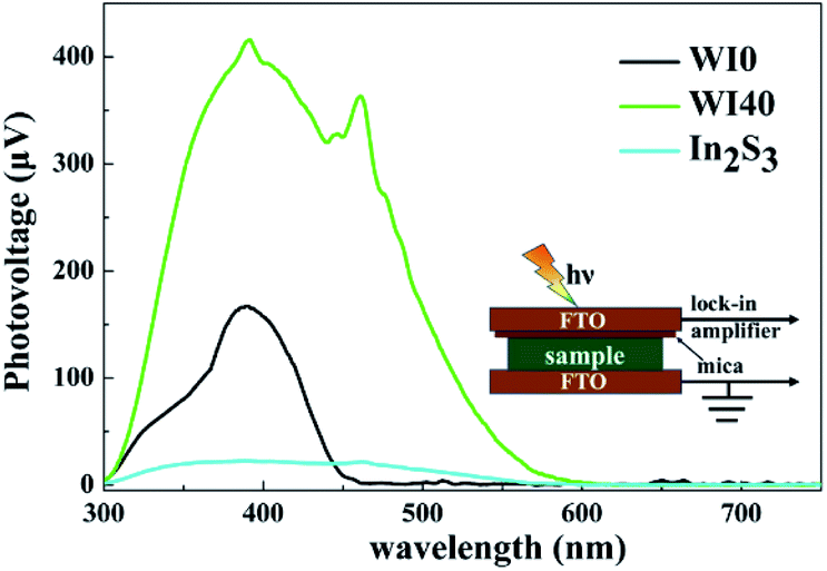 | ||
| Fig. 10 Surface photovoltage spectra of WI0, WI40 and In2S3. | ||
Furthermore, the transient photovoltage (TPV) technique was applied to investigate the dynamic properties of the photoexcited charge separation and transfer process of WI0, WI40 and In2S3. Fig. 11 illustrates the TPV results of prepared photocatalysts under 355 nm and 532 nm pulse laser irradiation on a normal timescale. The schematic diagram of the TPV test configuration is presented as well as that of the SPV test configuration, as seen in the inset of Fig. 10. Obviously, a negative TPV signal is observed for all the prepared photocatalysts, which implies the photoexcited electrons transfer to the top electrode. Moreover, a weak positive TPV signal is observed for all the prepared photocatalysts due to the existence of surface state.49,50 As shown in Fig. 11(a), only a weak signal is observed for the pure WO3 and In2S3 due to the poor separation efficiency of the pure WO3 and In2S3. Similarly, the TPV response intensity of WI40 is significantly stronger compared to that of pure WO3 and In2S3, which reveals that the synergistic reaction of WO3 and In2S3 is beneficial to the separation and transport of photoexcited charge carriers. The TPV response of the prepared photocatalysts shows the same results under 532 nm pulse laser irradiation, as shown in Fig. 11(b). That is to say, WI40 shows a higher photocatalytic water pollutant degradation efficiency, which is reasonable due to the synergistic reaction of WO3 and In2S3.
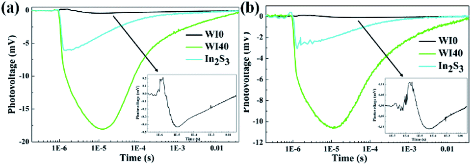 | ||
| Fig. 11 Transient photovoltage response of WI0, WI40 and In2S3. (a) The wavelength and the intensity of the laser are 355 nm and 100 μJ, respectively. (b) The wavelength and the intensity of the laser are 532 nm and 100 μJ, respectively. | ||
3.4. Exploration of photocatalytic degradation mechanism
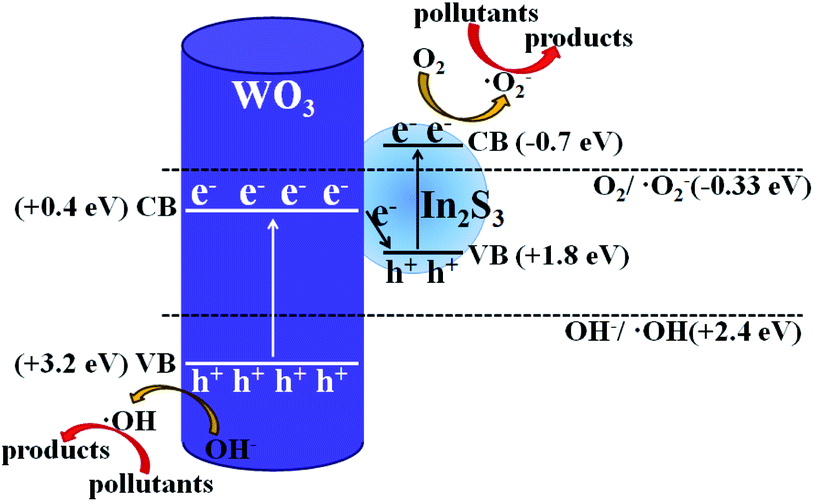
In order to further understand the photocatalytic degradation mechanism of In2S3/WO3 heterostructure, scavenger experiments for WI0 (Fig. 12(a)) and WI40 (Fig. 12(b)) were carried out to investigate the reactive oxidation species (ROSs) in the degradation process. It is worth noting that the degradation efficiencies decrease obviously both in the presence of potassium bromate and sodium oxalate in the WI0 photocatalytic degradation system, indicating that e− and h+ are the main ROS in the degradation process of WI0, while ˙O2− and ˙OH rarely exist. In contrast, all four types of ROS exist in the WI40 photocatalytic degradation system. The degradation efficiency decreases sharply in the presence of TEMPOL, indicating that ˙O2− is the major ROS in the degradation process of WI40. However, the degradation efficiencies decrease weakly both in the presence of potassium bromate and isopropanol, which means that h+ and ˙OH are the minor ROS. Besides, the degradation efficiency decreases with the addition of sodium oxalate, indicating that holes also take part in the oxidation reaction of pollutants. It should be noted that the concentration of e− and h+ reduce sharply in the WI40 system; this may be due to the fact that the photoexcited charges transfer rapidly to form ˙O2− and ˙OH. In fact, previous reports suggest that the CB position of In2S3 is at around −0.7 eV,23 and the redox potential of O2/˙O2− (−0.33 eV vs. NHE) is more negative than the CB of the In2S3; thus, the electrons in the CB of In2S3 could react with O2 to produce ˙O2−. This is consistent with the results of the scavenger experiments. Similarly, the VB position of WO3 (3.2 eV vs. NHE) is more positive than the redox potential of ˙OH/OH− (2.4 eV vs. NHE), and ˙OH could be generated through the reaction between holes in the VB and OH−.25,26 Therefore, the all-solid-state Z-scheme In2S3/WO3 heterostructure is proposed.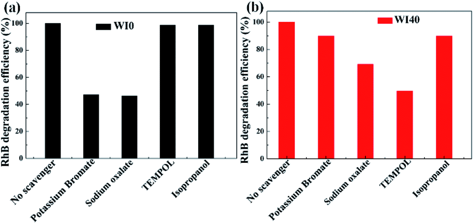 | ||
| Fig. 12 ROS scavenger experiments during the photodegradation of Rh B over (a) WI0 and (b) WI40 under visible light irradiation. | ||
Based on the above analysis of experimental results, the possible photocatalytic degradation mechanism with the all-solid-state Z-scheme In2S3/WO3 heterostructure is shown in Fig. 13. Previous reports confirmed that the energy band structures of WO3 and In2S3 are beneficial to the transfer of photoexcited electrons from the CB of WO3 to the VB of In2S3.23 Therefore, the charge recombination of electrons in WO3 and holes in In2S3 occurs at the contact interface between WO3 and In2S3; this leaves the electrons in the CB of In2S3 and holes in the VB of WO3 to take part in the photocatalytic degradation reaction directly, or generate the ˙O2− and ˙OH. In this way, the ˙O2− with stronger oxidation ability will participate in the oxidation reaction of pollutants and improve the photocatalytic degradation efficiency, as shown in Fig. 13. The above discussion confirms that the designed all-solid-state Z-scheme photocatalyst could promote photocatalytic water pollutant degradation efficiency and enhance the redox ability of the photocatalytic system distinctly.
 | ||
| Fig. 13 Possible photocatalytic pollutant degradation mechanism for the all-solid-state Z-scheme In2S3/WO3 photocatalyst. | ||
4 Conclusions
In summary, an all-solid-state Z-scheme In2S3/WO3 photocatalyst was successfully designed and synthesized via a facile method. The degradation efficiency of the In2S3/WO3 photocatalyst exhibits a significant improvement compared with the pure In2S3 and WO3. The results suggest that the all-solid-state Z-scheme In2S3/WO3 heterostructure is more beneficial to the photoexcited charge transfer at the contact interface with an unobstructed Z-scheme route, and thus the separation efficiency shows a clear improvement. In this way, the obtained In2S3/WO3 photocatalyst exhibits a significantly improved photocatalytic degradation performance toward Rh B and TCH, eventually. This work demonstrates that the all-solid-state Z-scheme photocatalyst could be accurately designed and prepared via a simple hydrothermal method, and it exhibits outstanding photocatalytic performance, presenting a novel route for the design of a highly efficient photocatalyst in the photocatalytic field.Conflicts of interest
There are no conflicts to declare.Acknowledgements
We are grateful to the National Natural Science Foundation of China (No. 61904070 and 51802129).Notes and references
- J. Qi, W. Zhang and R. Cao, Solar-to-Hydrogen energy conversion based on water splitting, Adv. Energy Mater., 2018, 8, 1701620 CrossRef.
- J. Liang, X. Li, Z. Yu, G. Zeng, Y. Luo, L. Jiang, Z. Yang, Y. Qian and H. Wu, Amorphous MnO2 modified biochar derived from aerobically composted swine manure for adsorption of Pb(II) and Cd(II), ACS Sustainable Chem. Eng., 2017, 5, 5049 CrossRef CAS.
- L. Jiang, X. Yuan, Y. Pan, J. Liang, G. Zeng, Z. Wu and H. Wang, Doping of graphitic carbon nitride for photocatalysis: a review, Appl. Catal., B, 2017, 217, 388 CrossRef CAS.
- X. J. Wen, C. Niu, L. Zhang, C. Liang and G. Zeng, A novel Ag2O/CeO2 heterojunction photocatalysts for photocatalytic degradation of enrofloxacin: possible degradation pathways, mineralization activity and an in depth mechanism insight, Appl. Catal., B, 2018, 221, 701 CrossRef CAS.
- C. Zhou, C. Lai, D. Huang, G. Zeng, C. Zhang, M. Cheng, L. Hu, J. Wan, W. Xiong, M. Wen, X. Wen and L. Qin, Highly porous carbon nitride by supramolecular preassembly of monomers for photocatalytic removal of sulfamethazine under visible light driven, Appl. Catal., B, 2018, 220, 202 CrossRef CAS.
- M. Solakidou, A. Giannakas, Y. Georgiou, N. Boukos, M. Louloudi and Y. Deligiannakis, Efficient photocatalytic water-splitting performance by ternary CdS/Pt-N-TiO2 and CdS/Pt-N,F-TiO2: interplay between CdS photocorrosion and TiO2-dopping, Appl. Catal., B, 2019, 254, 194 CrossRef CAS.
- T. Yang, K. Xue, J. Wang, R. He, R. Sun, U. Omeoga, T. Yang, W. Wang, J. Wang and Y. Hu, Investigation of electron beam irradiation on In2S3-MxInySz (M = Bi or La) Z-scheme heterojunctions for efficient and stable degradation of water pollutants, J. Alloys Compd., 2020, 818, 152873 CrossRef CAS.
- V. Jayarama, B. Palanivel, C. Ayappan, M. Chellamuthu and A. Mani, CdZnS solid solution supported Ce2Sn2O7 pyrochlore photocatalyst that proves to be an efficient candidate towards the removal of organic pollutants, Sep. Purif. Technol., 2019, 224, 405–420 CrossRef.
- E. Hua, S. Jin, X. Wang, S. Ni, G. Liu and X. Xu, Ultrathin 2D type-II p–n heterojunctions La2Ti2O7/In2S3 with efficient charge separations and photocatalytic hydrogen evolution under visible light illumination, Appl. Catal., B, 2019, 245, 733 CrossRef CAS.
- J. Low, J. Yu, M. Jaroniec, S. Wageh and A. Al-Ghamdi, Heterojunction Photocatalysts, Adv. Mater., 2017, 29, 1601694 CrossRef.
- H. Wang, L. Zhang, Z. Chen, J. Hu, S. Li, Z. Wang, J. Liu and X. Wang, Semiconductor heterojunction photocatalysts: design, construction, and photocatalytic performances, Chem. Soc. Rev., 2014, 43, 5234 RSC.
- H. Yu, R. Shi, Y. Zhao, G. Waterhouse, L. Wu, C. Tung and T. Zhang, Smart Utilization of Carbon Dots in Semiconductor Photocatalysis, Adv. Mater., 2016, 28, 9454 CrossRef CAS.
- Q. Li, X. Li, S. Wageh, A. Al-Ghamdi and J. Yu, CdS/Graphene Nanocomposite Photocatalysts, Adv. Energy Mater., 2015, 5, 1500010 CrossRef.
- X. Li, J. Yu and M. Jaroniec, Hierarchical photocatalysts, Chem. Soc. Rev., 2016, 45, 2603 RSC.
- H. Li, W. Tu, Y. Zhou and Z. Zou, Z-Scheme Photocatalytic Systems for Promoting Photocatalytic Performance: Recent Progress and Future Challenges, Adv. Sci., 2016, 3, 1500389 CrossRef.
- P. Zhou, J. Yu and M. Jaroniec, All-Solid-State Z-Scheme Photocatalytic Systems, Adv. Mater., 2014, 26, 4920 CrossRef CAS.
- T. Pan, D. Chen, W. Xu, J. Fang, S. Wu, Z. Liu, K. Wu and Z. Fang, Anionic polyacrylamide-assisted construction of thin 2D-2D WO3/g-C3N4 Step-scheme heterojunction for enhanced tetracycline degradation under visible light irradiation, J. Hazard. Mater., 2020, 393, 122366 CrossRef CAS.
- M. Kim, Y. Kim, S. Lim, S. Kim and S. In, Efficient visible light-induced H2 production by Au@CdS/TiO2 nanofibers: synergistic effect of core-shell structured Au@CdS and densely packed TiO2 nanoparticles, Appl. Catal., B, 2015, 166, 423 CrossRef.
- X. Yin, J. Liu, W. Jiang, X. Zhang, J. Hu and L. Wan, Urchin-like Au@CdS/WO3 micro/nano heterostructure as a visible-light driven photocatalyst for efficient hydrogen generation, Chem. Commun., 2015, 51, 13842 RSC.
- J. Wang, Y. Zhang, X. Wang and W. Su, Simultaneous enhancements in photoactivity and anti-photocorrosion of Z-scheme Mn0.25Cd0.75S/WO3 for solar water splitting, Appl. Catal., B, 2020, 268, 118444 CrossRef CAS.
- J. Li, H. Cheng, Y. Chiu and Y. Hsu, ZnO-Au-SnO2 Z-scheme photoanodes for remarkable photoelectrochemical water splitting, Nanoscale, 2016, 8, 15720 RSC.
- X. Wen, C. Niu, L. Zhang, C. Liang, H. Guo and G. Zeng, Photocatalytic degradation of ciprofloxacin by a novel Z-scheme CeO2-Ag/AgBr photocatalyst: influencing factors, possible degradation pathways, and mechanism insight, J. Catal., 2018, 358, 141 CrossRef CAS.
- H. Li, Y. Gao, Y. Zhou, F. Fan, Q. Han, Q. Xu, X. Wang, M. Xiao, C. Li and Z. Zou, Construction and Nanoscale Detection of Interfacial Charge Transfer of Elegant Z-Scheme WO3/Au/In2S3 Nanowire Arrays, Nano Lett., 2016, 16, 5547 CrossRef CAS.
- S. Bao, Q. Wu, S. Chang, B. Tian and J. Zhang, Z-scheme CdS-Au-BiVO4 with enhanced photocatalytic activity for organic contaminant decomposition, Catal. Sci. Technol., 2017, 1(7), 124–132 RSC.
- J. Jiang, Y. Song, X. Wang, T. Li, M. Li, Y. Lin, T. Xie and S. Dong, Enhancing aqueous pollutant photodegradation via a Fermi level matched Z-scheme BiOI/Pt/g-C3N4 photocatalyst: unobstructed photogenerated charge behavior and degradation pathway exploration, Catal. Sci. Technol., 2020, 10, 3324 RSC.
- J. Zhang, Y. Ma, Y. Du, H. Jiang, D. Zhou and S. Dong, Carbon nanodots/WO3 nanorods Z-scheme composites: Remarkably enhanced photocatalytic performance under broad spectrum, Appl. Catal., B, 2017, 209, 253 CrossRef CAS.
- X. Yuan, L. Jiang, J. Liang, Y. Pan, J. Zhang, H. Wang, L. Leng, Z. Wu, R. Guan and G. Zeng, In situ synthesis of 3D microsphere-like In2S3/InVO4 heterojunction with efficient photocatalytic activity for tetracycline degradation under visible light irradiation, Chem. Eng. J., 2019, 356, 371 CrossRef CAS.
- T. Yan, T. Wu, Y. Zhang, M. Sun, X. Wang, Q. Wei and B. Du, Fabrication of In2S3/Zn2GeO4 composite photocatalyst for degradation of acetaminophen under visible light, J. Colloid Interface Sci., 2017, 506, 197 CrossRef CAS.
- Z. Li, Z. Zhou, J. Ma, Y. Li, W. Peng, G. Zhang, F. Zhang and X. Fan, Hierarchical photocatalyst of In2S3 on exfoliated MoS2 nanosheets for enhanced visible-light-driven Aza-Henry reaction, Appl. Catal., B, 2018, 237, 288 CrossRef CAS.
- H. Xu, Y. Wang, X. Dong, N. Zheng, H. Ma and X. Zhang, Fabrication of In2O3/In2S3 microsphere heterostructures for efficient and stable photocatalytic nitrogen fixation, Appl. Catal., B, 2019, 257, 117932 CrossRef CAS.
- L. Zhang, S. Li, B. Liu, D. Wang and T. Xie, Highly Efficient CdS/WO3 Photocatalysts: Z-Scheme Photocatalytic Mechanism for Their Enhanced Photocatalytic H2 Evolution under Visible light, ACS Catal., 2014, 4, 3724 CrossRef CAS.
- B. Li, L. Sun, J. Bian, N. Sun, J. Sun, L. Chen, Z. Li and L. Jing, Controlled synthesis of novel Z-scheme iron phthalocyanine/porous WO3 nanocomposites as efficient photocatalysts for CO2 reduction, Appl. Catal., B, 2020, 270, 118849 CrossRef CAS.
- N. Omrani and A. Nezamzadeh-Ejhieh, A comprehensive study on the enhanced photocatalytic activity of Cu2O/BiVO4/WO3 nanoparticles, J. Photochem. Photobiol., A, 2020, 389, 112223 CrossRef CAS.
- Q. Qiu, S. Li, J. Jiang, D. Wang, Y. Lin and T. Xie, Improved Electron Transfer between TiO2 and FTO Interface by N-Doped Anatase TiO2 Nanowires and Its Applications in Quantum Dot-Sensitized Solar Cells, J. Phys. Chem. C, 2017, 121, 21560 CrossRef CAS.
- X. Wei, T. Xie, Y. Zhang, D. Wang and J. Chen, The Effect of Al3+ Treatment on Charge Dynamics in Dye-sensitized Nanocrystal-line TiO2 Solar Cells Explored by Photovoltage Measurements, Mater. Chem. Phys., 2010, 122, 259 CrossRef CAS.
- J. Jiang, H. Wang, X. Chen, S. Li, T. Xie, D. Wang and Y. Lin, Enhanced photocatalytic degradation of phenol and photogenerated charges transfer property over BiOI-loaded ZnO composites, J. Colloid Interface Sci., 2017, 494, 130 CrossRef CAS.
- L. Zhang, T. Jiang, S. Li, Y. Lu, L. Wang, X. Zhang, D. Wang and T. Xie, Enhancement of Photocatalytic H2 Evolution on Zn0.8Cd0.2S Loaded with CuS as Cocatalyst and its Photogenerated Charge Transfer Properties, Dalton Trans., 2013, 42, 12998 RSC.
- Y. Zhang, J. Yu, M. Jaroniec and J. Gong, Noble Metal-Free Reduced Graphene Oxide-ZnxCd1-xS Nanocomposite with Enhanced Solar Photocatalytic H2-Production Performance, Nano Lett., 2012, 12, 4584 CrossRef.
- Y. Ma, J. Jiang, A. Zhu, P. Tan, Y. Bian, W. Zeng, H. Cui and J. Pan, Enhanced visible-light photocatalytic degradation by Mn3O4/CeO2 heterojunction: a Z-scheme system photocatalyst, Inorg. Chem. Front., 2018, 5, 2579 RSC.
- B. He, M. Feng, X. Chen, D. Zhao and J. Sun, One-pot construction of chitin-derived carbon/g-C3N4 heterojunction for the improvement of visible-light photocatalysis, Appl. Surf. Sci., 2020, 527, 146737 CrossRef CAS.
- C. Yao, X. Wang, W. Zhao, T. Li, Y. He, X. Ran and L. Guo, Probing the facet-dependent intermediate in the visible-light degradation of RhB by carbon-coated anatase TiO2 nanoparticles, J. Alloys Compd., 2020, 846, 156335 CrossRef CAS.
- B. Song, Q. Wang, L. Wang, J. Lin, X. Wei, V. Murugadoss, S. Wu, Z. Guo, T. Ding and S. Wei, Carbon nitride nanoplatelet photocatalysts heterostructured with B-doped carbon nanodots for enhanced photodegradation of organic pollutants, J. Colloid Interface Sci., 2020, 559, 124 CrossRef CAS.
- G. Ma, J. Lu, Q. Meng, H. Lv, L. Shui, Y. Zhang, M. Jin, Z. Chen, M. Yuan, R. Nötzel, X. Wang, C. Wang, J. Liu and G. Zhou, Synergistic effect of Cu-ion and WO3 nanofibers on the enhanced photocatalytic degradation of Rhodamine B and aniline solution, Appl. Surf. Sci., 2019, 451, 306 CrossRef.
- X. Yuan, L. Jiang, X. Chen, L. Leng, W. Hou, Z. Wu, T. Xiong, J. Liang and G. Zeng, Highly efficient visible-light-induced photoactivity of Z-scheme Ag2CO3/Ag/WO3 photocatalysts for organic pollutant degradation, Environ. Sci.: Nano, 2017, 4, 2175 RSC.
- X. Gao, C. Liang, K. Gao, X. Li, J. Liu and Q. Li, Z-scheme heterojunction Ag3PO4/BiVO4 with exposing high-active facets and stretching spatial charge separation ability for photocatalytic organic pollutants degradation, Appl. Surf. Sci., 2020, 524, 146506 CrossRef CAS.
- Z. Shi, Y. Zhang, T. Liu, W. Cao, L. Zhang, M. Li and Z. Chen, Synthesis of BiOBr/Ag3PO4 heterojunctions on carbon-fiber cloth as filter-membrane-shaped photocatalyst for treating the flowing antibiotic wastewater, J. Colloid Interface Sci., 2020, 575, 183 CrossRef CAS.
- H. Yin, Y. Cao, T. Fan, B. Qiu, M. Zhang, J. Yao, P. Li, X. Liu and S. Chen, Construction of carbon bridged TiO2/CdS tandem Z-scheme heterojunctions toward efficient photocatalytic antibiotic degradation and Cr (VI) reduction, J. Alloys Compd., 2020, 824, 153915 CrossRef CAS.
- S. Li, Q. Zhao, D. Meng, D. Wang and T. Xie, Fabrication of metallic charge transfer channel between photoanode Ti/Fe2O3 and cocatalyst CoOx: an effective strategy for promoting photoelectrochemical water oxidation, J. Mater. Chem. A, 2016, 4, 16661 RSC.
- X. Wei, T. Xie, D. Xu, Q. Zhao, S. Pang and D. Wang, A study of the dynamic properties of photo-induced charge carriers at nanoporous TiO2/conductive substrate interfaces by the transient photovoltage technique, Nanotechnology, 2008, 27, 275707 CrossRef.
- Y. Zhang, T. Xie, T. Jiang, X. Wei, S. Pang, X. Wang and D. Wang, Surface photovoltage characterization of a ZnO nanowire array/CdS quantum dot heterogeneous film and its application for photovoltaic devices, Nanotechnology, 2010, 23, 7217 Search PubMed.
Footnote |
| † Electronic supplementary information (ESI) available. See DOI: 10.1039/d0ra09315g |
| This journal is © The Royal Society of Chemistry 2021 |