DOI:
10.1039/D0RA08040C
(Paper)
RSC Adv., 2021,
11, 1109-1114
A self-supported electrode for supercapacitors based on nanocellulose/multi-walled carbon nanotubes/polypyrrole composite
Received
20th September 2020
, Accepted 20th December 2020
First published on 6th January 2021
Abstract
A robust self-supported electrode based on nanocellulose fibers (CNF), multi-walled carbon nanotubes (CNT), and polypyrrole (PPy) was prepared by a facile combination of ultrasonic dispersion and consequent in situ polymerization. In addition, the feasibility of utilizing this ternary composite as an electrode for supercapacitors was studied. The results revealed that the obtained CNF/CNT/PPy composite exhibited a large specific capacitance of 200.8 F g−1 at 0.5 A g−1. Equally important, the electrode capacitance retained about 90% of its initial value after 5000 charge/discharge cycles at a current density of 1 A g−1, which thus demonstrated its excellent cycling stability. The simple integration route and outstanding electrochemical properties distinguish this new composite as a prospective candidate for use as a high-performance electrode in supercapacitors.
1. Introduction
Research on electrochemical energy storage technology has expanded rapidly in recent years, and this growth can be attributed to the significant role that it fulfills in our daily lives.1–3 Supercapacitors (SCs), one of the most common energy storage devices, have captivated the attention of scientists throughout the world as they possess high power densities, can undergo fast charging–discharging processes, and offer outstanding cyclic performance.4,5 Based on the active materials used for the electrodes as well as the charge storage mechanism, there are two main categories of SCs that have received the most attention: electric double-layer capacitors (EDLCs) and pseudocapacitors.6 The electrodes of EDLCs are usually composed of various carbon-based materials, such as carbon nanotubes (CNT),7 reduced graphene oxide (rGO),8,9 and so forth. EDLCs store charge via the direct physical adsorption and desorption of ions rather than through faradaic reactions at the interface between the electrode and the electrolyte solution.10 As the structure of the electrode does not alter during the charging–discharging process, EDLCs are endowed with long service lifetimes.11 Pseudocapacitors, which are typically comprised of metal oxides/hydroxides12,13 or conductive polymers,14,15 store energy via reversible faradaic processes which can occur on both the surface and within the active materials. Because they utilize rapid redox reactions, pseudocapacitors exhibit much higher specific capacitances in comparison with EDLCs.
Polypyrrole (PPy) has been adopted as an ideal electrode material for pseudocapacitors due to its high conductivity, facile fabrication, and good redox properties.16 Liu prepared a hybrid electrode in which the PPy nanotubes (PNT) was used as a substrate for in situ growth of NiCo-MOF nanosheets, and the obtained NiCo-MOF@PNTs delivered large specific capacitance (1109 F g−1 at 0.5 A g−1) and superior rate capability.17 However, its poor cycling stability has seriously hindered further application of PPy in supercapacitors.18,19 To address this issue, considerable efforts have been dedicated toward improving the stability of PPy during the charging–discharging process. Zhitomirsky and co-workers introduced tiron20 and sulfanilic acid azochromotrop21 into PPy-based electrodes and obtained supercapacitors exhibiting capacitance retention values of 91.5% and 93.1%, respectively, after 1000 cycles. Liu developed a CoO@PPy nanowire electrode for supercapacitors by compositing metal oxide with PPy, and the resultant hybrid electrode exhibited outstanding durability that lasted up to 20![[thin space (1/6-em)]](https://www.rsc.org/images/entities/char_2009.gif) 000 cycles.22 Another effective method to overcome the defects of PPy electrodes involved integrating PPy with carbon-based materials such as rGO23,24 and CNT.25,26 It is noteworthy that CNT have been considered as promising candidates for the strengthening of PPy-based electrodes due to their innately excellent conductivity and mechanical stability. In addition, chemical oxidative polymerization has been widely used to prepare PPy/CNT composites due to the simplicity and affordability of this process.27 A typical chemical oxidative polymerization process involves a combination of the dispersion of CNT and a pyrrole monomer in a mixed solution and the subsequent addition of an oxidant to initiate the polymerization. However, the resultant PPy/CNT composites are usually obtained in a powdered form and thus additional binders are needed to fabricate electrodes for supercapacitors.28
000 cycles.22 Another effective method to overcome the defects of PPy electrodes involved integrating PPy with carbon-based materials such as rGO23,24 and CNT.25,26 It is noteworthy that CNT have been considered as promising candidates for the strengthening of PPy-based electrodes due to their innately excellent conductivity and mechanical stability. In addition, chemical oxidative polymerization has been widely used to prepare PPy/CNT composites due to the simplicity and affordability of this process.27 A typical chemical oxidative polymerization process involves a combination of the dispersion of CNT and a pyrrole monomer in a mixed solution and the subsequent addition of an oxidant to initiate the polymerization. However, the resultant PPy/CNT composites are usually obtained in a powdered form and thus additional binders are needed to fabricate electrodes for supercapacitors.28
Cellulose is the most abundant biopolymer on earth, and it is widely used as a component of supercapacitors.29–32 Cellulose nanofibers (CNF), one type of cellulose-based materials, are a sustainable and promising family of binder materials due to their natural abundance, and superb properties.33 The numerous hydroxyl groups that reside on the cellulose backbone can form strong hydrogen bonds with CNT as well as PPy chains. In this study, a CNF/CNT/PPy composite that served as a self-supporting electrode for supercapacitors was prepared via a chemical oxidative polymerization method. In this composite the CNF serves not only as a binder but also as a dispersant for the CNT suspension.34 Meanwhile, PPy endows the composite with good conductivity and a large specific capacitance. The CNT can provide a reliable support for the conductive PPy chains as well as an effective channel for charge transportation which can impart the electrode with excellent performance. The morphologies of the composites were investigated, and the electrochemical performances of these materials were evaluated.
2. Experimental
2.1 Materials
Multi-walled carbon nanotubes functionalized with carboxylic acid group (CNT) (purity > 98%, diameter 10–20 nm and length 10–30 μm) were obtained from Beijing DK Nano Technology Co., Ltd (China). Pyrrole monomer (99%), phytic acid (50%), and ammonium persulfate (APS, 98%) were all purchased from Aladdin Reagent Co., Ltd. (China) and used as received without further purification. An aqueous dispersion of cellulose nanofibers (CNF, 1.0 wt%) was provided by Guilin Qihong Technology Co., Ltd. (China).
2.2 Preparation of the CNF/CNT/PPy composites
The CNF dispersion (10.0 g) was initially diluted to 0.1 wt% with deionized water via stirring for 30 min in a beaker. Subsequently, CNT (0.03 g) were added into the beaker under continuous magnetic stirring, which was followed by sonication for 30 min to form a homogenous CNF/CNT dispersion. A mixture solution containing pyrrole (0.42 mL) and phytic acid (1.00 mL) was then added into the CNF/CNT dispersion. The resultant mixture was cooled to 0–5 °C in a refrigerator, and subsequently mixed with a solution of ammonium persulfate (3.75 g, 20 wt%) to initiate the oxidative polymerization. After this reaction had proceeded for 6 h in an ice bath, the CNF/CNT/PPy composite was obtained via vacuum filtration, washing by ethanol and DI water, and was subsequently dried at room temperature. For comparison, CNF/CNT and CNF/PPy were also prepared. The absolute loadings of CNF, CNT and PPy in each final electrode were illustrated in Table 1.
Table 1 The absolute loadings of CNF, CNT and PPy in CNF/CNT, CNF/PPy, CNF/CNT/PPy
| |
CNF (g) |
CNT (g) |
PPy (g) |
| CNF/CNT |
0.10 |
0.03 |
— |
| CNF/PPy |
0.10 |
— |
0.40 |
| CNF/CNT/PPy |
0.10 |
0.03 |
0.40 |
2.3 Characterization
The morphology and structure of the composite were observed with a scanning electron microscope (SEM, Hitachi S3400N, Japan). A Fourier-transform infrared spectrometer (FT-IR, Nicolet 5100) and an X-ray diffractometer (XRD, Rigaku D/MAX-1200) were used to characterize the functional groups and composition of the material.
2.4 Electrochemical measurements
The electrochemical performances were studied with the use of a CHI 760 electrochemical workstation (CH Instruments Inc., China) that was operated in a three-electrode configuration. A small piece of the as-prepared composite was used as the working electrode directly, while a standard calomel electrode (SCE) and a platinum foil served as a reference electrode and a counter electrode, respectively. Cyclic voltammetry (CV) tests were performed at scanning rates ranging from 5 to 100 mV s−1 over a potential window of −0.2 to 0.8 V. Galvanostatic charge–discharge (GCD) measurements were conducted at current densities ranging from 0.5 to 4.0 A g−1. Electrochemical impedance spectroscopy (EIS) data were recorded in the frequency range from 0.05 Hz to 100 kHz with an alternate current amplitude of 5 mV. All of these experiments were conducted in a 1 M H2SO4 electrolyte solution. The specific capacitance Cm (F g−1) is calculated from the GCD curve via eqn (1):| |
 | (1) |
where Cm denotes the specific capacitance, I is the current (A), Δt is the discharge time (s), m is the mass of the active material, and ΔV is the potential range.
3. Results and discussion
3.1 Morphology and properties
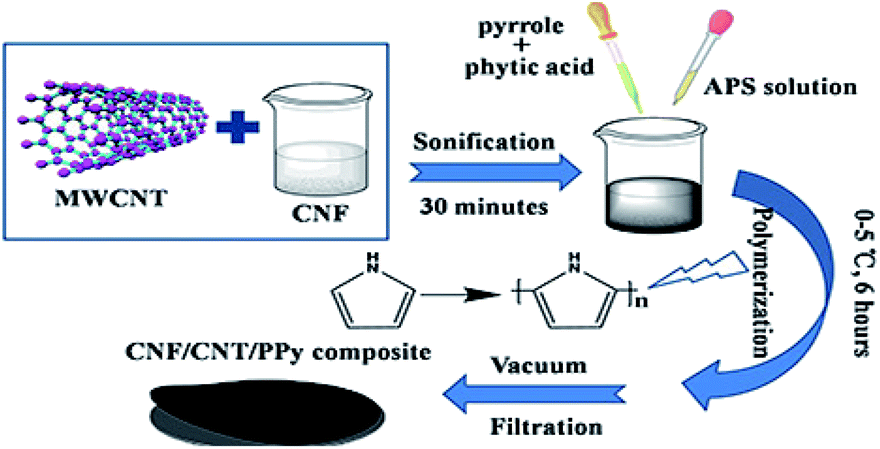
A schematic depiction of the preparation process leading to the CNF/CNT/PPy composite is shown in Fig. 1. CNF were chosen as the binder of the composite as they were endowed with numerous functional groups which can form abundant inter-molecular hydrogen bonds between different components. Moreover, the CNF also acted as good dispersants for the CNT to yield a uniform CNF/CNT suspension.34,35 With the addition of CNF, the zeta potential of the CNF/CNT is −51.0 mV, which is much higher than that of the pure CNT suspension (−14.5 mV). Therefore, the CNF/CNT was endowed with sufficient electro-static repulsions which can overcome the van der Waals' attraction between tubes, leading to an excellent dispersion performance. The CNF/CNT/PPy composite was subsequently prepared by in situ polymerization of pyrrole and the CNF/CNT dispersion, with APS and phytic acid introduced as an initiator and a dopant, respectively. The entire polymerization process was conducted at a low temperature in the range of 0–5 °C to slow down the reaction speed and reduce defects in the resultant PPy structure. The CNT/PPy composite without adding CNF was also prepared with the same process for comparison. It was found that the obtained CNT/PPy composite was in powder form instead of a self-supported film. This proved CNF played an indispensable role in constructing the self-supported composite electrode.
 |
| | Fig. 1 Schematic illustration depicting the fabrication process leading to the CNF/CNT/PPy composite. | |
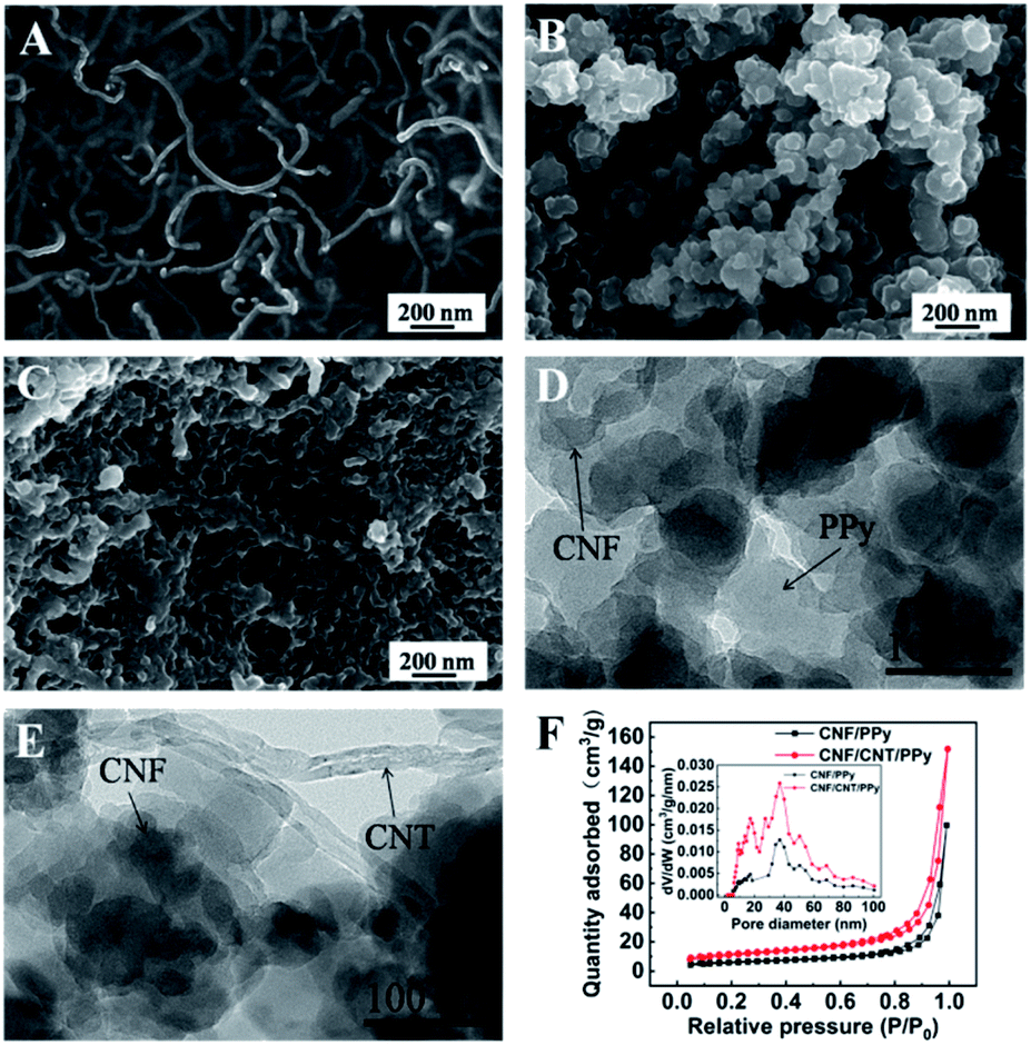
The morphologies of the CNF/CNT, CNF/PPy, and CNF/CNT/PPy composites observed via SEM are shown in Fig. 2. The CNF/CNT (Fig. 2A) presented a network which was stacked by fibers. In sharp contrast, the SEM images showed the porous morphologies of the CNF/PPy (Fig. 2B) and CNF/CNT/PPy (Fig. 2C) composites, which were composed of interconnected particles with diameters in the range of 50 to 200 nm. These nanoparticles were produced during the in situ polymerization of PPy, and it was anticipated that the porous structure would facilitate the transport of electrons and ions during the charging and discharging processes. The TEM images of the CNF/PPy (Fig. 2D) and CNF/CNT/PPy (Fig. 2E) confirmed the good distribution of CNF throughout the composites. To further investigated the porous structure of the CNF/PPy and CNF/CNT/PPy, the nitrogen absorption–desorption behaviour of samples were studied. As depicted of the isotherms in Fig. 2F, the CNF/CNT/PPy was more porous than the CNF/PPy. Additionally, the surface area of the CNF/CNT/PPy calculated by Brunauer–Emmett–Teller (BET) method was 34.63 m2 g−1, which is bigger than that of the CNF/PPy (20.21 m2 g−1). The pore size distribution of the composites was presented in the inset of Fig. 2F, and the results demonstrated that the pore diameter was mainly around 40 nm. In addition, the pore volume of the CNF/CNT/PPy was larger than that of the CNF/PPy, which ensured the large specific surface area. The distinctive porous structure and large specific surface area of the CNF/CNT/PPy facilitate the ion transmission, demonstrating its potential use as an electrode of the supercapacitors.
 |
| | Fig. 2 SEM images of the CNF/CNT (A), CNF/PPy (B), and CNF/CNT/PPy (C); TEM images of CNF/PPy (D), and CNF/CNT/PPy (E); the nitrogen absorption–desorption isotherms and pore size distribution of CNF/PPy and CNF/CNT/PPy composites (F). | |
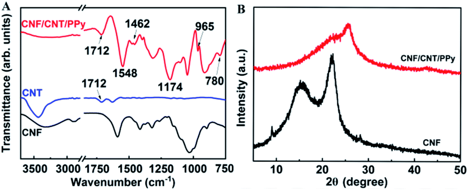
The surfaces of the obtained composites were also characterized by infrared spectroscopy (Fig. 3A). It is readily apparent that several new characteristic peaks appeared in the FT-IR spectrum of the CNF/CNT/PPy composite. The peak observed at 1712 cm−1 may be attributed to a C![[double bond, length as m-dash]](https://www.rsc.org/images/entities/char_e001.gif) O stretching vibration, which existed in the CNT.36 The peaks at 1462 and 1548 cm−1 respectively corresponded to the symmetric and asymmetric stretching vibrations of the pyrrole rings. Meanwhile, the peaks near 965 and 780 cm−1 demonstrated the presence of polymerized pyrrole in the composite and the peak at 1174 cm−1 indicated the doping state of PPy.37 These spectra confirmed that PPy was indeed incorporated into the electrode material, and this can be further supported by the obtained XRD data (Fig. 3B). Obviously, the diffraction peaks of the CNFs at 15.4° and 22.6° were covered by a wide diffraction peak (2θ = 14°–36°), which was attributable to the amorphous structure of PPy.38,39
O stretching vibration, which existed in the CNT.36 The peaks at 1462 and 1548 cm−1 respectively corresponded to the symmetric and asymmetric stretching vibrations of the pyrrole rings. Meanwhile, the peaks near 965 and 780 cm−1 demonstrated the presence of polymerized pyrrole in the composite and the peak at 1174 cm−1 indicated the doping state of PPy.37 These spectra confirmed that PPy was indeed incorporated into the electrode material, and this can be further supported by the obtained XRD data (Fig. 3B). Obviously, the diffraction peaks of the CNFs at 15.4° and 22.6° were covered by a wide diffraction peak (2θ = 14°–36°), which was attributable to the amorphous structure of PPy.38,39
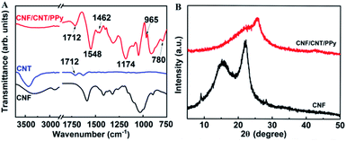 |
| | Fig. 3 FT-IR spectra of the CNF, CNT and CNF/CNT/PPy composite (A); XRD patterns of the CNF and the CNF/CNT/PPy composite (B). | |
3.2 Electrochemical analysis of the composites
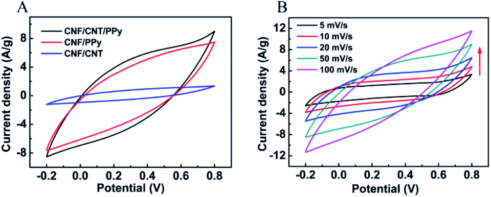
The electrochemical behaviours of the as-prepared CNF/CNT/PPy composites were studied with the use of an electrochemical workstation in a 1 M H2SO4 aqueous solution. Fig. 4A shows voltammograms of the CNF/CNT, CNF/PPy, and CNF/CNT/PPy composites that were obtained at a scanning rate of 50 mV s−1. It can be seen that all of the CV curves exhibited similar profiles in the potential window ranging from −0.2 to 0.8 V while the areas corresponding to the closed curves of CNF/PPy and CNF/CNT/PPy are much larger than that of CNF/CNT. This behaviour suggested that the specific capacitance of the CNF/CNT composite was far less than those of the other two electrode samples, which is consistent with previous findings.40 As can be seen in Fig. 4B, the CV curves of the CNF/CNT/PPy composite exhibited a quasi-rectangular shape without any substantive changes except that the area of the close curve increased as the scan rate was increased from 5 to 100 mV s−1, thus demonstrating the good rate performance and electrochemical capacitance of the electrode.
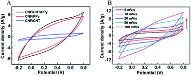 |
| | Fig. 4 The CV curves of the CNF/CNT, CNF/PPy, and CNF/CNT/PPy composites at 50 mV s−1 (A) and CV curves of the CNF/CNT/PPy composite at various scan rates (B). | |
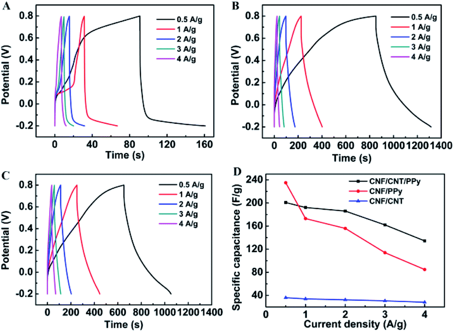
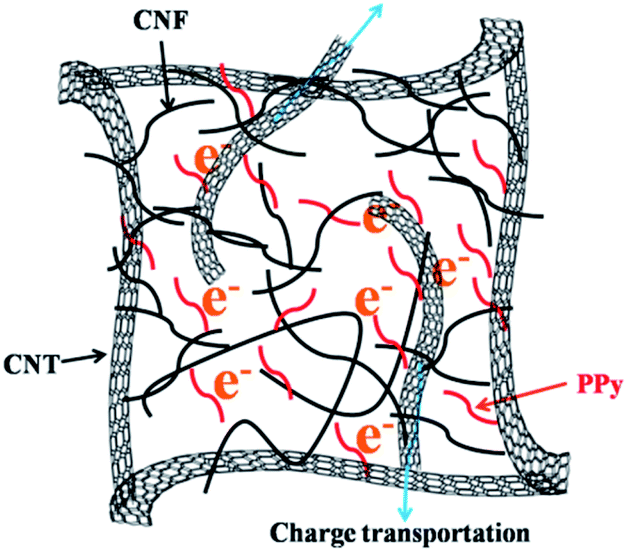
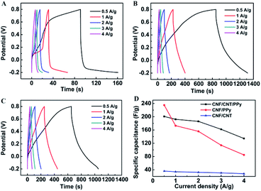
To further investigate the charge storage performances of the composites, GCD tests were conducted at various current densities over the same voltage range that was employed for the CV experiments. The potential–time curves for the CNF/CNT, CNF/PPy, and CNF/CNT/PPy electrodes are respectively shown in Fig. 5A–C. A distinct feature of these curves is that their discharge domains and the corresponding charge counterparts of these electrodes were not symmetric. A significant voltage drop was visible during the initiation of the GCD record, which was triggered by the equivalent internal resistance.35 It should be noted here that the voltage drops exhibited by the CNF/PPy and CNF/CNT/PPy electrode were distinctly smaller than that of the CNF/CNT composite, indicating that the resistance of the former two electrodes were smaller than that of the latter one. The gravimetric specific capacitances of these electrodes at various current densities were obtained from the GCD curves based on eqn (1) and are summarized in Fig. 5D. It is evident that the CNF/PPy and CNF/CNT/PPy electrodes possessed much higher specific capacitances than that of their CNF/CNT counterpart at both low and high current densities. The reason for this was that the theoretical capacitance of PPy was much higher compared with that of the CNT.41,42 At a low current density (0.5 A g−1), the specific capacitances of CNF/PPy and CNF/CNT/PPy reached up to 235 and 200.8 F g−1, respectively. This can be attributed to the pseudocapacitance behaviour of PPy and the porous structures of these two composites (Fig. 2B and C). Although the specific capacitances of these two electrodes diminished as the current density increased, the specific capacitance of the CNF/PPy electrode decreased far more dramatically than that of its CNF/CNT/PPy counterpart. Typically, a capacitance of 134.4 F g−1 was still obtained for the CNF/CNT/PPy composite at a current density of 4 A g−1, whereas the capacitance of the CNF/PPy electrode was only 84.8 F g−1 at the same current density. This can be explained based on the energy-storage mechanism of the CNF/CNT/PPy electrode, which is shown in Fig. 6. These two composites exhibited superior specific capacitances due to the reversible redox reaction of the PPy component during the charging and discharging process. At a high current density, the CNT present in the CNF/CNT/PPy composite served as effective channels for charge transportation, and therefore the capacitance still remained at 67% even when the current density was increased to 4 A g−1. What's more, the specific capacitance of the CNF/CNT/PPy was also superior than that of some reported similar electrodes which were listed in Table 2, such as the rGO/PPy hybrid paper (190 F g−1)43 and the carbonaceous shell-coated PPy electrode (114.08 F g−1).44
 |
| | Fig. 5 GCD curves of CNF/CNT (A), CNF/PPy (B), and CNF/CNT/PPy (C) composites at various current densities; specific capacitances at various current densities for these three composites (D). | |
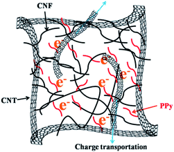 |
| | Fig. 6 Schematic diagram showing the energy-storage mechanism involving the CNF/CNT/PPy composite. | |
Table 2 Comparison of the specific capacitance of the CNF/CNT/PPy with the results of previous related reports
| |
Specific capacitance (F g−1) |
Ref. |
| rGO/PPy hybrid paper |
190 |
43 |
| Carbonaceous shell@PPy |
114.08 |
44 |
| PEDOT/NCC film |
117.02 |
45 |
| CBF/PPy–rGO |
130.8 |
46 |
| CNF/CNT/PPy |
200.8 |
This work |
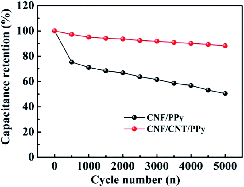
The cycling performance is an important indicator of the electrochemical performances of electrodes as well as their suitability for use in supercapacitors. The cycling stability of CNF/PPy and CNF/CNT/PPy electrodes were evaluated via GCD tests at a current density of 1 A g−1. As depicted in Fig. 7, the capacitance retention ratio for the CNF/PPy electrode was ∼50% after 5000 cycles. This result was attributed to the inevitable shrinkage of the PPy resulting from the doping–dedoping process during repeated cycling.47 In contrast, the capacitance loss exhibited by CNF/CNT/PPy was less than 15%, implying that the electrode possessed reasonable cycling stability. These results suggested that the CNT component could provide a robust support for the PPy network and alleviate the shrinkage and swelling of PPy during repeated charge–discharge cycles.
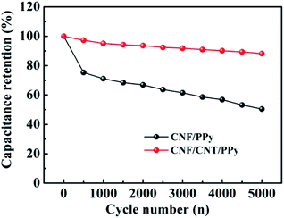 |
| | Fig. 7 Cycling stability of the CNF/PPy and CNF/CNT/PPy electrodes at a current density of 1 A g−1. | |
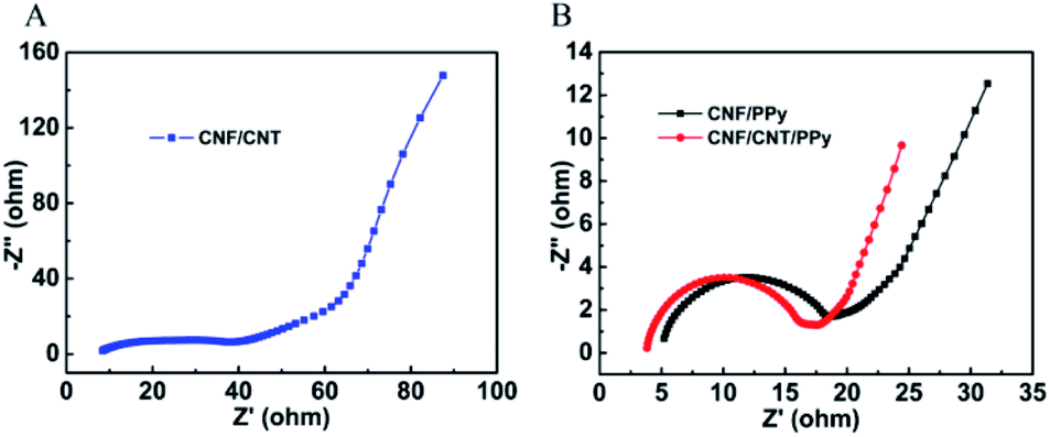
EIS measurements of the composites were also obtained. Fig. 8 shows the Nyquist plots of impedance for the CNF/CNT, CNF/PPy, and CNF/CNT/PPy electrodes in the frequency range between 0.1 to 105 Hz. Notably, similar trends were observed in all three of these plots: an approximate semicircle was present at the high frequency region and a nearly straight line was visible at the low frequency region. The diameter of the semicircle corresponded to the charge transfer resistance (Rct) of the interface between the electrode and the electrolyte. Meanwhile, the intercept of the semicircle with the Z′ axis in the high frequency domain represented the equivalent series resistance (Rs). The values of Rct and Rs for these three electrodes were obtained by fitting the experimental data and are listed in Table 3. The Rs value of the CNF/CNT/PPy electrode is 3.40 Ω, which is lower than those of its CNF/PPy (4.21 Ω) and CNF/CNT (6.85 Ω) counterparts. In addition, the CNF/CNT/PPy electrode possessed the lowest Rct value among these three composites, suggesting the good supercapacitor behaviour of the developed electrode. In the low frequency region, the slope of the line represented the diffusive resistance (Warburg impedance) of the electrode. It was evident that the slope of the line for the CNF/CNT/PPy electrode was larger than that of its CNF/PPy counterpart, demonstrating that ion diffusion occurred more freely in the former than in the latter.
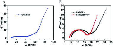 |
| | Fig. 8 Nyquist plots for the CNF/CNT (A), CNF/PPy, and CNF/CNT/PPy (B) electrodes. | |
Table 3 The Rs and Rct values for the CNF/CNT, CNF/PPy, and CNF/CNT/PPy electrodes
| |
Rs (Ω) |
Rct (Ω) |
| CNF/CNT/PPy |
3.40 |
13.44 |
| CNF/PPy |
4.21 |
15.56 |
| CNF/CNT |
6.85 |
28.50 |
4. Conclusion
In summary, we have developed a novel type of self-supported electrode for use in supercapacitors through a simple vacuum filtration method using environment-friendly CNF as a binder. The obtained composite electrode showed a high specific capacitance of 200.8 F g−1, benefiting from the porous structure of PPy. As the CNT can provide a robust support to the PPy chains, the CNF/CNT/PPy electrode exhibited excellent cycling performance with its capacitance retention remaining about 90% after 5000 cycles at 1A g−1. In addition, the CNF/CNT/PPy electrode had a better rate capability than that of CNF/PPy due to the effective channel for charge transportation provided by CNT. With advantages such as facile preparation, high specific capacitance, and excellent cycling stability, the CNF/CNT/PPy composite demonstrated its remarkable potential applicability as an electrode for supercapacitors.
Conflicts of interest
The authors declare that they have no conflict of interest.
Acknowledgements
This research was supported by GDAS' Project of Science and Technology Development (2020), 2020GDASYL-0102003.
References
- X. Lang, A. Hirata, T. Fujita and M. Chen, Nat. Nanotechnol., 2011, 6, 232–236 CrossRef CAS.
- X. Zang, Y. Hou, T. Wang, R. Zhang, F. Kang and H. Zhu, Sci. China Mater., 2019, 62, 947–954 CrossRef CAS.
- J. Yan, Q. Wang, T. Wei and Z. Fan, Adv. Energy Mater., 2014, 4, 1300816 CrossRef.
- P. Simon, Y. Gogotsi and B. Dunn, Science, 2014, 343, 1210–1211 CrossRef CAS.
- H. Mei, Y. Mei, S. Zhang, Z. Xiao, B. Xu, H. Zhang, L. Fan, Z. Huang, W. Kang and D. Sun, Inorg. Chem., 2018, 57, 10953–10960 CrossRef CAS.
- C. Zhong, Y. Deng, W. Hu, J. Qiao, L. Zhang and J. Zhang, Chem. Soc. Rev., 2015, 44, 7484–7539 RSC.
- E. Senokos, V. Reguero, L. Cabana, J. Palma, R. Marcilla and J. J. Vilatela, Adv. Mater. Technol., 2017, 2, 1600290 CrossRef.
- F. Li, X. Jiang, J. Zhao and S. Zhang, Nano Energy, 2015, 16, 488–515 CrossRef CAS.
- J. Yang and S. Gunasekaran, Carbon, 2013, 51, 36–44 CrossRef CAS.
- A. C. Forse, C. Merlet, J. M. Griffin and C. P. Grey, J. Am. Chem. Soc., 2016, 138, 5731–5744 CrossRef CAS.
- R. Karthick and F. Chen, Carbon, 2019, 150, 292–310 CrossRef CAS.
- H. Chen, L. Hu, M. Chen, Y. Yan and L. Wu, Adv. Funct. Mater., 2014, 24, 934–942 CrossRef CAS.
- H. B. Li, M. H. Yu, F. X. Wang, P. Liu, Y. Liang, J. Xiao, C. X. Wang, Y. X. Tong and G. W. Yang, Nat. Commun., 2013, 4, 1894 CrossRef CAS.
- X. Huang and L. Gou, Appl. Surf. Sci., 2019, 487, 68–76 CrossRef CAS.
- X. Wang, H. Wei, X. Liu, W. Du, X. Zhao and X. Wang, Nanotechnology, 2019, 30, 325401 CrossRef CAS.
- Y. Huang, H. Li, Z. Wang, M. Zhu, Z. Pei, Q. Xue, Y. Huang and C. Zhi, Nano Energy, 2016, 22, 422–438 CrossRef CAS.
- Y. X. Liu, Y. Z. Wang, Y. J. Chen, C. Wang and L. Guo, Appl. Surf. Sci., 2020, 507, 145089 CrossRef CAS.
- Y. Song, J. L. Xu and X. X. Liu, J. Power Sources, 2014, 249, 48–58 CrossRef CAS.
- Y. Song, T. Y. Liu, X. X. Xu, D. Y. Feng, Y. Li and X. X. Liu, Adv. Funct. Mater., 2015, 25, 4626–4632 CrossRef CAS.
- K. Shi and I. Zhitomirsky, J. Power Sources, 2013, 240, 42–49 CrossRef CAS.
- S. Chen and I. Zhitomirsky, J. Power Sources, 2013, 243, 865–871 CrossRef CAS.
- C. Zhou, Y. Zhang, Y. Li and J. Liu, Nano Lett., 2013, 13, 2078–2085 CrossRef CAS.
- Y. Liu, H. Wang, J. Zhou, L. Bian, E. Zhu, J. Hai, J. Tang and W. Tang, Electrochim. Acta, 2013, 112, 44–52 CrossRef CAS.
- X. Zhang, J. Zhang, Y. Chen, K. Cheng, J. Yan, K. Zhu, K. Ye, G. Wang, L. Zhou and D. Cao, J. Colloid Interface Sci., 2019, 536, 291–299 CrossRef CAS.
- Z. H. Chang, D. Y. Feng, Z. H. Huang and X. X. Liu, Chem. Eng. J., 2018, 337, 552–559 CrossRef CAS.
- Y. Chen, L. Du, P. Yang, P. Sun, X. Yu and W. Mai, J. Power Sources, 2015, 287, 68–74 CrossRef CAS.
- N. G. Sahoo, Y. C. Jung, H. H. So and J. W. Cho, Synth. Met., 2007, 157, 374–379 CrossRef CAS.
- T. M. Wu and S. H. Lin, J. Polym. Sci., Part B: Polym. Phys., 2006, 44, 1413–1418 CrossRef CAS.
- S. Zhou, X. Kong, B. Zheng, F. Huo, M. Stromme and C. Xu, ACS Nano, 2019, 13, 9578–9586 CrossRef CAS.
- N. Sheng, S. Chen, J. Yao, F. Guan, M. Zhang, B. Wang, Z. Wu, P. Ji and H. Wang, Chem. Eng. J., 2019, 368, 1022–1032 CrossRef CAS.
- D. C. Wang, H. Y. Yu, D. Qi, M. Ramasamy, J. Yao, F. Tang, K. M. C. Tam and Q. Ni, ACS Appl. Mater. Interfaces, 2019, 11, 24435–24446 CrossRef CAS.
- H. Zhuo, Y. Hu, Z. Chen and L. Zhong, Carbohydr. Polym., 2019, 215, 322–329 CrossRef CAS.
- H. Lu, M. Behm, S. Leijonmarck, G. Lindbergh and A. Cornell, ACS Appl. Mater. Interfaces, 2016, 8, 18097–18106 CrossRef CAS.
- M. M. Hamedi, A. Hajian, A. B. Fall, K. Hakansson, M. Salajkova, F. Lundell, L. Wagberg and L. A. Berglund, ACS Nano, 2014, 8, 2467–2476 CrossRef CAS.
- J. M. Malho, P. Laaksonen, A. Walther, O. Ikkala and M. B. Linder, Biomacromolecules, 2012, 13, 1093–1099 CrossRef CAS.
- S. H. Kim, S. Y. Kim and U. S. Shin, Compos. Sci. Technol., 2016, 126, 78–85 CrossRef CAS.
- H. Fu, Z. J. Du, W. Zou, H. Q. Li and C. Zhang, J. Mater. Chem. A, 2013, 1, 14943 RSC.
- R. Li, Y. Yang, H. Li, R. Fu, W. Tan, Y. Qin, Y. Tao and Y. Kong, Electrochim. Acta, 2019, 311, 123–131 CrossRef CAS.
- M. Hou, M. Xu, Y. Hu and B. Li, Electrochim. Acta, 2019, 313, 245–254 CrossRef CAS.
- A. Afzal, F. A. Abuilaiwi, A. Habib, M. Awais, S. B. Waje and M. A. Atieh, J. Power Sources, 2017, 352, 174–186 CrossRef CAS.
- C. G. Liu, M. Liu, F. Li and H. M. Cheng, Appl. Phys. Lett., 2008, 92, 143108 CrossRef.
- G. A. Snook, P. Kao and A. S. Best, J. Power Sources, 2011, 196, 1–12 CrossRef CAS.
- K. W. Shu, C. Y. Wang, C. Zhao, Y. Ge and G. G. Wallace, Electrochim. Acta, 2016, 212, 561–571 CrossRef CAS.
- T. Y. Liu, L. Finn, M. H. Yu, H. Y. Wang, T. Zhai, X. H. Lu, Y. X. Tong and Y. Li, Nano Lett., 2014, 14, 2522–2527 CrossRef CAS.
- R. Ravit, J. Abdullah, I. Ahmad and Y. Sulaimana, Carbohydr. Polym., 2019, 203, 128–138 CrossRef CAS.
- H. A. A. Bashid, H. N. Lim, S. Kamaruzaman, S. A. Rashid, R. Yunus, N. M. Huang, C. Y. Yin, M. M. Rahman, M. Altarawneh, Z. T. Jiang and P. Alagarsamy, Nanoscale Res. Lett., 2017, 12, 246 CrossRef.
- Y. Han and L. Dai, Macromol. Chem. Phys., 2019, 220, 1800355 CrossRef.
|
| This journal is © The Royal Society of Chemistry 2021 |
Click here to see how this site uses Cookies. View our privacy policy here. 
 Open Access Article
 This Open Access Article is licensed under a Creative Commons Attribution-Non Commercial 3.0 Unported Licence
 *a and
Weiqu Liu*ab
*a and
Weiqu Liu*ab