DOI:
10.1039/D0RA06080A
(Paper)
RSC Adv., 2021,
11, 1952-1959
Design and characterization of oil-in-water nanoemulsion for enhanced oil recovery stabilized by amphiphilic copolymer, nonionic surfactant, and LAPONITE® RD
Received
12th July 2020
, Accepted 24th November 2020
First published on 7th January 2021
Abstract
The application of nanotechnology in the oil and gas industry has attracted widespread attention in recent years. This study aims to develop a nanoemulsion (NE) for use in enhanced oil recovery (EOR). The NE stabilized by anion amphiphilic copolymer, nonionic surfactant (Brij30) and modified LAPONITE® RD was prepared by the phase inversion composition (PIC) method. The appearance of the emulsion is translucent and the average particle size is less than 60 nm. The micromorphology and interfacial tension (IFT) are examined using transmission electron microscopy (TEM) and a spinning drop IFT meter, respectively. The NE possesses good stability evaluated by conductivity and particle size tests. The absolute value of the zeta potential of NE increases when modified LAPONITE® RD is added. In a core flooding experiment with an artificial sandstone core, the NE flooding increased oil recovery by 23.53% compared to water flooding.
1. Introduction
In general, a considerable amount of crude oil remains in the pores of the reservoir after primary and secondary oil recovery. Through enhanced oil recovery (EOR) technology, the rate of oil production can be increased.1,2 Chemical EOR is a widespread technique that uses chemical additives (such as surfactants, alkalis, polymers, and mixtures thereof) in water to improve the efficiency of oil recovery. Chemical flooding can promote oil production through various mechanisms, such as in situ emulsification, mobility ratio control, and reduction of the interfacial tension between the oil and displacement phase.3–6
In recent years, the application of nanotechnology has been the focus of EOR research. A variety of organic and inorganic nanomaterials have been reported to improve oil recovery.7–9 Nanomaterials do not have major effect on the permeability of the reservoir due to their small particle size. They can improve oil recovery through wettability alteration, interface tension reduction, viscosity increment, and other mechanisms.10–14 Nanosilica is the most widely studied nanomaterial in EOR research. In particular, various nanofluids containing silica with different particle sizes and surface properties have been investigated.15–18 The performance of polymer and nanoparticle mixing systems obtained by polymerization or blending can be improved by increasing the viscosity, temperature tolerance, and salt resistance.19–22 Layered nanoparticles, including nanoclay23,24 and grapheme oxide,25,26 have also been used in EOR.
Emulsion flooding can be a promising EOR method that increases the macroscopic and microscopic displacement efficiencies.27–30 The transport phenomena of displacement fluids containing chemical additives in porous media are important for EOR. Nanoemulsions (NEs) contain small particles and are more stable than ordinary emulsions. Small NE droplets can penetrate deep pores causing residual crude oil to flow out. High and low-energy methods are currently used to prepare NEs. High-energy methods, such as ultrasound, usually have high energy consumption, and the emulsions have small droplets and long-term emulsification stability. Low-energy methods, such as phase transition components (PIC) and phase transition temperature (PIT) methods, require less energy and simple preparation equipment.31–36 Recently, the application of NE to EOR has attracted the attention of researchers. Kumar et al. prepared different NEs using surfactants and polymeric surfactants.37–39 The properties of the NEs (such as stability, interface tension, and viscosity) were studied for EOR applications. They also prepared NEs stabilized by surfactant with nanoparticle or surfactant–polymer–nanoparticle assemblies. The addition of nanoparticles can reduce the size of oil droplets and improve emulsion stability. The mechanisms of oil displacement were investigated in terms of wettability and interfacial activity.40–43 Zhang et al. investigated oil/water interfacial turbulence (the Marangoni effect) in NE to improve water flooding for heavy-oil recovery. This could help to remove and emulsify oil from oil sand.44 Different NE formulations consisting of xylene, Triton X-100, and zirconium oxide nanoparticles were prepared and used for EOR in unconsolidated porous systems by Jalilian et al.45 These studies demonstrate that NEs have great potential in enhanced oil recovery.
Inspired by previous works, this study investigated NEs stabilized with random copolymers, surfactant Brij30 and LAPONITE® ORD for use in EOR. The properties of the emulsion, such as the particle size, potential, interfacial tension and emulsion stability, were measured using different techniques. On this basis, the application of emulsions in EOR was further investigated using a core flooding experiment. To our knowledge, such research has not been conducted elsewhere.
2. Experimental section
2.1. Materials
Lauryl polyoxyethylene ether (Brij 30), sodium p-styrenesulfonate hydrate (SSS) and dodecyl methacrylate (LMA) were purchased from Aladdin Reagent Corporation. Azobisisobutyronitrile (AIBN) was purchased from Xiya Chemical Industry Co. Ltd. Gemini surfactant G16-2-16 (50 wt% in water) was received from Daochun Chemical Technology Co. Ltd. LAPONITE® RD was purchased from BYK Additives and Instruments. Liquid paraffin was obtained from Tianjin Fuchen Chemical Reagents Factory. Sodium chloride (NaCl) was purchased from Sinopharm Chemical Reagent Co., Ltd. Crude oil was obtained from Panyu, Guangdong. The crude oil had viscosity of 9.0 mPa s, as measured by a Brookfield DV3T viscometer at 25 °C, and the density was 0.846 g cm−3. Deionized water was used in this study.
2.2. Preparation of organically modified LAPONITE® RD
First, 1.0 g of LAPONITE® RD was dispersed in 100 mL of deionized water in a three necked flask. Then, the mixture was stirred for 30 min and sonicated for 10 min. A given amount of intercalation agent G16-2-16 was dissolved in 25 mL of deionized water, and the solutions were added to the LAPONITE® RD dispersion and stirred at 80 °C for 8 h. The modified LAPONITE® RD samples were named ORD1, ORD2, and ORD3 according to the mass (0.1 g, 0.3 g, and 0.7 g) of the modifier.
2.3. Synthesis and characterization of amphiphilic copolymer
Amphiphilic copolymer was synthesized with SSS and LMA monomers using free radical polymerization with AIBN as the initiator. The synthesis and evaluation of the copolymer were presented in our previous work.46 The ratio of hydrophilic and hydrophobic groups affects the properties of the copolymer. In this study, a copolymer of SL75 (feed ratio of hydrophilic to lipophilic of 7 to 5) was selected based on the interfacial activity and emulsifying ability.
2.4. Nanoemulsion preparation
The NE preparation method was described in our previous work.46 The emulsifiers (SL75, Brij30 and ORD) were dissolved in an oil phase (liquid paraffin) under magnetic stirring before emulsification, and the oil/emulsifier ratio was fixed at 1![[thin space (1/6-em)]](https://www.rsc.org/images/entities/char_2009.gif) :1. The SL75 dosage was 0.24 g, and the Brij30 dosage was 0.54 g. The ORD concentrations were 0, 4.2 × 10⁻²% w/v, and 8.4 × 10⁻²% w/v. Then, 20 mL of deionized water was added dropwise into the oil phase in a 70 °C water bath with magnetic stirring. After preparation, the samples were cooled to room temperature (approximately 20 °C).
:1. The SL75 dosage was 0.24 g, and the Brij30 dosage was 0.54 g. The ORD concentrations were 0, 4.2 × 10⁻²% w/v, and 8.4 × 10⁻²% w/v. Then, 20 mL of deionized water was added dropwise into the oil phase in a 70 °C water bath with magnetic stirring. After preparation, the samples were cooled to room temperature (approximately 20 °C).
2.5. Characterization and measurement
The infrared spectrum was analyzed using a Tensor II Fourier infrared spectrometer (BRUKER, USA). Thermal gravimetric analysis was conducted using a Diamond TG/DTA synchronal thermal analyzer (PerkinElmer, USA). The heating rate was 10 °C min−1, and the maximum temperature was 800 °C. The microstructure images of the NE was observed using a JEM-2100 (JEOL, Japan) transmission electron microscope. The diluted NE was dripped onto a carbon membrane, and 3 wt% phosphotungstic acid solution was added to the dried samples for negative dyeing. After drying, the samples were measured by the TEM. The interfacial tension (IFT) between the crude oil and NE was determined using a TX-500C (POWEREACH, China) IFT meter through spinning drop method. The outer phase was NE, and the test was conducted at a rotation speed of 6000 rpm. The change in conductivity with temperature was measured by DDS-307A (Leici, China) conductivity meter. The particle size and zeta potential of the emulsions were measured using a Zetasizer Nano ZS (Malvern Instruments, UK).
The experimental setup for the core flooding experiment mainly included positive displacement pump (ISCO, America), slug cylinder, core holder, and collector for displaced fluids. The pore volume of the core was measured before the experiment. The NE flooding process consisted of the following steps. (1) The core was placed in the core holder and the pressure was set to 2 MPa, then degassed crude oil was injected at a speed of 0.2 mL min−1 until no water was produced at the outlet. (2) Brine water was injected at a constant rate of 0.2 mL min−1 for water flooding until no oil was produced at the outlet. (3) NE flooding was injected at a constant rate of 0.2 mL min−1.
3. Results and discussion
3.1. Characterization of LAPONITE® RD
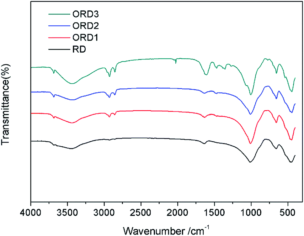
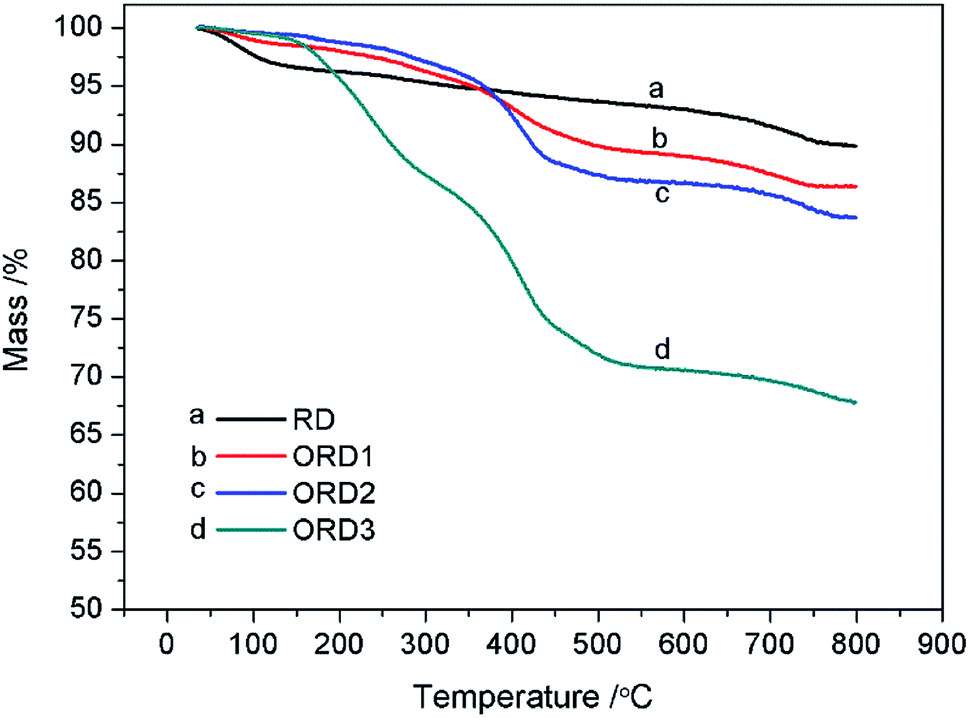
The Fourier transform infrared (FT-IR) spectra of LAPONITE® RD and the modified LAPONITE® RD are shown in Fig. 1. The peak at approximately 1000 cm−1 corresponds to the Si–O stretching vibration absorption peak, and the peak at 3500 cm−1 is related to the stretching vibration absorption peaks of Al–OH and Si–OH. The peaks at 2850 and 2920 cm−1 correspond to the –CH2– stretching vibration of G16-2-16. After the intercalation reaction, the LAPONITE® RD was mixed with the modified agent G16-2-16. When more of this agent was added, the –CH2– peak became stronger. Fig. 2 shows the thermal gravimetric analysis (TGA) curves for LAPONITE® RD and modified LAPONITE® RD. It is clear that the mass of LAPONITE® lost at high temperatures increased when the modifier was added. Moreover, ORD3 lost more weight than the other samples at high temperatures because it contained more of modifier. The FT-IR and TGA analyses indicate that LAPONITE® RD was achieved to be modified by an intercalation agent.
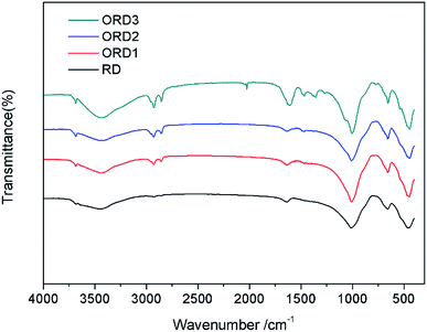 |
| | Fig. 1 FT-IR spectra of LAPONITE® and modified LAPONITE®. | |
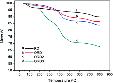 |
| | Fig. 2 TGA of LAPONITE® and modified LAPONITE®. | |
3.2. Appearance and morphology of nanoemulsion
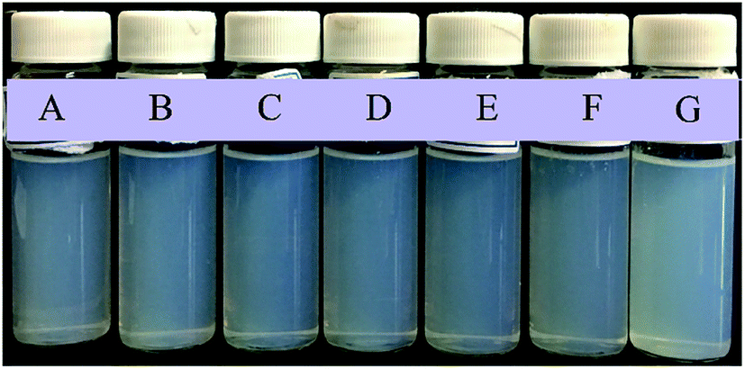
The nanoemulsion was successfully prepared using the PIC method stabilized by emulsifiers (SL75, Brij30, and/or ORD) at constant temperature. As shown in Fig. 3, all the NEs are translucent, which corresponds to the small size of the droplets. The addition of ORD will result in the reduction of light transmittance. For convenience, the samples with 4.2 × 10⁻²% w/v and 8.4 × 10⁻²% w/v of ORD are denoted a and b, respectively.
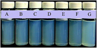 |
| | Fig. 3 Photos of NEs stabilized by SL, Brij30, and (A: without ORD, B: ORD1a, C: ORD1b, D: ORD2a, E: ORD2b, F: ORD3a, G: ORD3b). | |
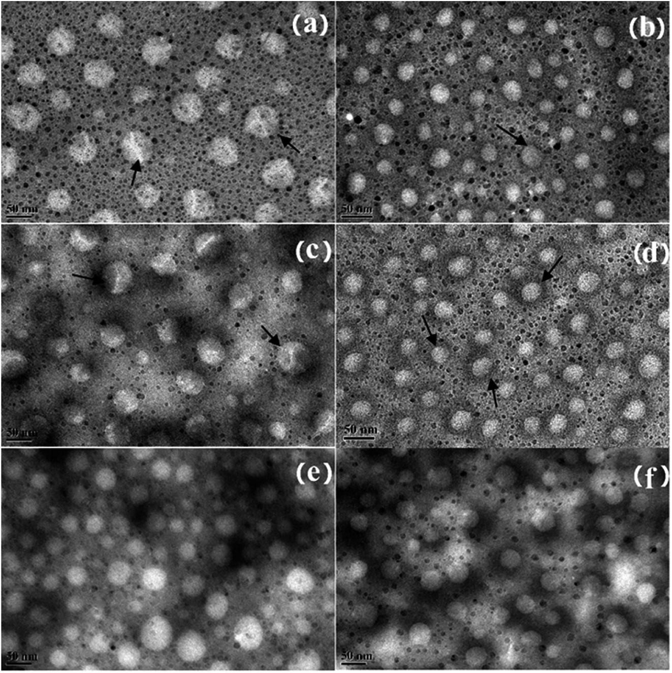
The micromorphology of the NE was observed using TEM. As shown in Fig. 4, the NEs with ORD have an average droplet size of less than 60 nm. The layered structure can be seen clearly on the surface of the NE droplets in Fig. 4 (a) and (c). When 8.4 × 10⁻²% w/v of ORD was added, the droplets in the NE were smaller than when ORD 4.2 × 10⁻²% w/v of ORD was added. This could be a result of extrusion by the ORD lamellar layers distributed in the droplet inter-space during water evaporation. A black coating around the droplets can be seen clearly in Fig. 4(b) and (d), which may be due to the modified LAPONITE® covering the surface.
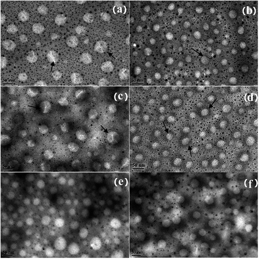 |
| | Fig. 4 TEM image of NEs formed from SL, Brij30, and (a) ORD1a, (b) ORD1b, (c) ORD2a, (d) ORD2b, (e) ORD3a, (f) ORD3b. | |
3.3. Particle size and zeta potential of nanoemulsion
The average particle size and polydispersity index (PDI) of the NEs are shown in the Table 1. At first, the particle size and PDI both increased, then they both decreased when ORD was added. The average particle sizes ranged from 48.2 to 58.01 nm, which corresponds to the TEM results. The emulsion with nanoscale droplets can enter smaller pores in the oil reservoir than an ordinary emulsion, which is helpful for oil recovery. The zeta potential of the NE is also shown in Table 1, and all of the samples were negatively charged. For the NEs with ORD1, the absolute value of the zeta potential reached a maximum when the amount of ORD1 was 4.2 × 10⁻²% w/v. For the NEs with ORD2 and ORD3, the absolute values increased with the increase of the amount of nanoparticles. The absolute values of the zeta potential for all of the NEs increased, in comparison to the original NE stabilized by the surfactant and polymer when ORD was added. This increase in the zeta potential could enhance the electrostatic repulsion of NE droplets, which will improve the stability of the emulsion. Furthermore, the addition of nanoparticles could increase the absolute value of zeta potential, as reported in other studies.39,40
Table 1 Average particle size and zeta potential of NEs
| Sample |
NE |
NE ORD1a |
NE ORD1b |
NE ORD2a |
NE ORD2b |
NE ORD3a |
NE ORD3b |
| d (nm) |
50.45 |
55.1 |
48.2 |
58.01 |
52.11 |
52.17 |
50.61 |
| PDI |
0.141 |
0.275 |
0.155 |
0.29 |
0.251 |
0.266 |
0.186 |
| Zeta (mV) |
−14.7 |
−18.3 |
−16.6 |
−16.3 |
−17.0 |
−18.3 |
−22.4 |
3.4. Interfacial tension of nanoemulsion
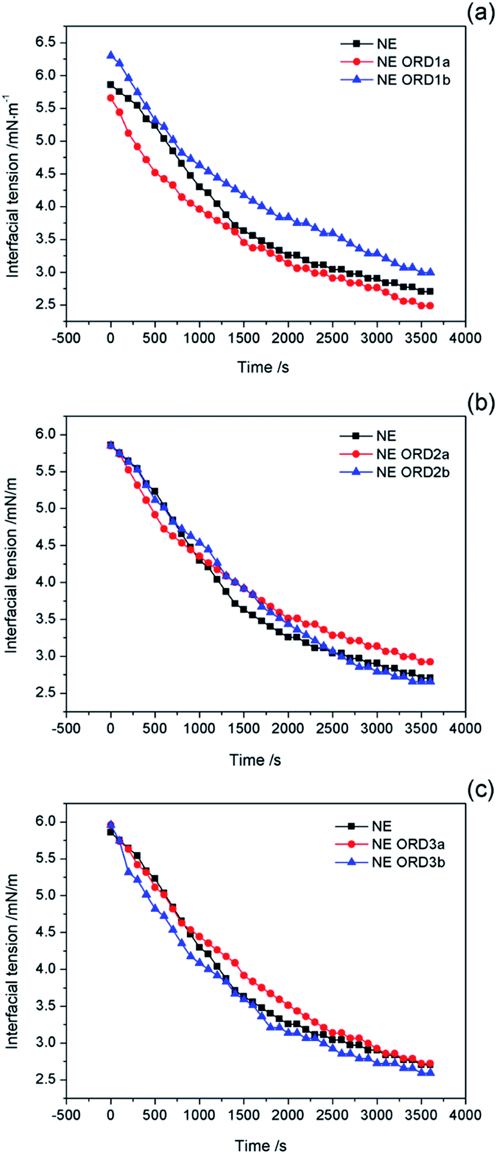
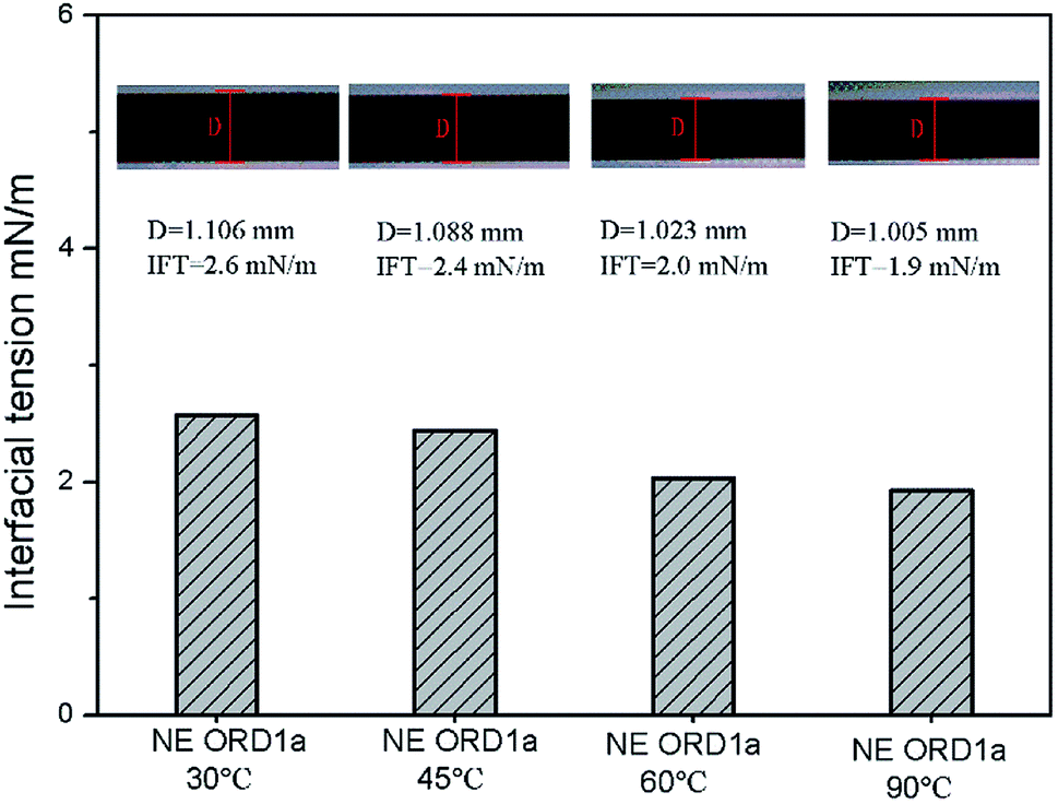
Interfacial tension is an important factor for oil displacement. The variation curves for crude oil/NE IFT over time were measured using the spinning drop method at 45 °C, as shown in Fig. 5. Overall, ORD only had a small effect on the oil–water IFT because the ORD dosage was small. Among the NEs with ORD systems, the IFT of NE with ORD1 showed the obvious change and crude oil/NE IFT decreased from 2.7 to 2.4 mN m−1 when 4.2 × 10⁻²% w/v of ORD1 was added. When 8.4 × 10⁻²% w/v of ORD1 was added, the IFT increased to 2.9 mN m−1. Based on these results, the 4.2 × 10⁻²% w/v NE with ORD1was selected for the further study of displacement experiment. The IFT measurements were repeated at 30 °C, 60 °C, 90 °C using the NE containing ORD1a. The test time was 3600 s, and the images for the spinning drop IFT analysis were incorporated. As depicted in Fig. 6, the IFT decreased from 2.6 mN m−1 to 1.9 mN m−1 as the temperature increased, but the change was not substantial overall.
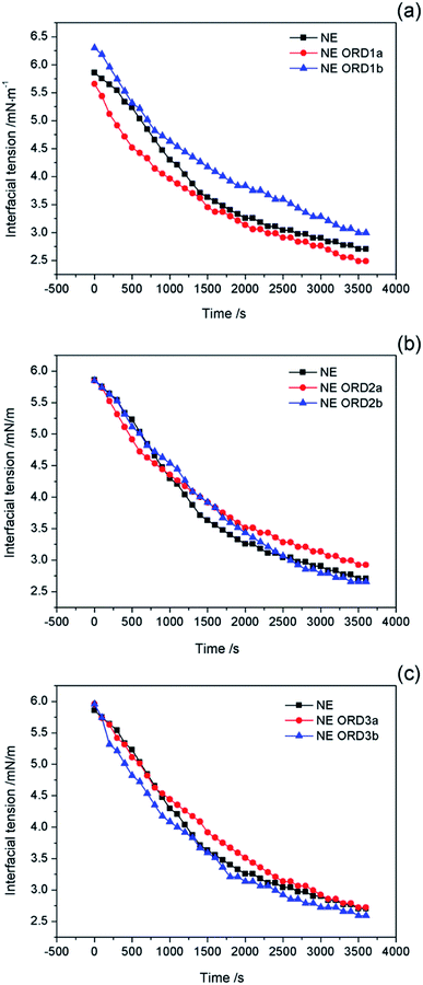 |
| | Fig. 5 Interfacial tension of crude oil/nanoemulsions with (a) ORD1, (b) ORD2 and (c) ORD3 as a function of time at 45 °C. | |
 |
| | Fig. 6 Interfacial tension between crude oil and NEs with ORD1 at 30 °C, 45 °C, 60 °C, 90 °C. | |
3.5. Emulsion stability
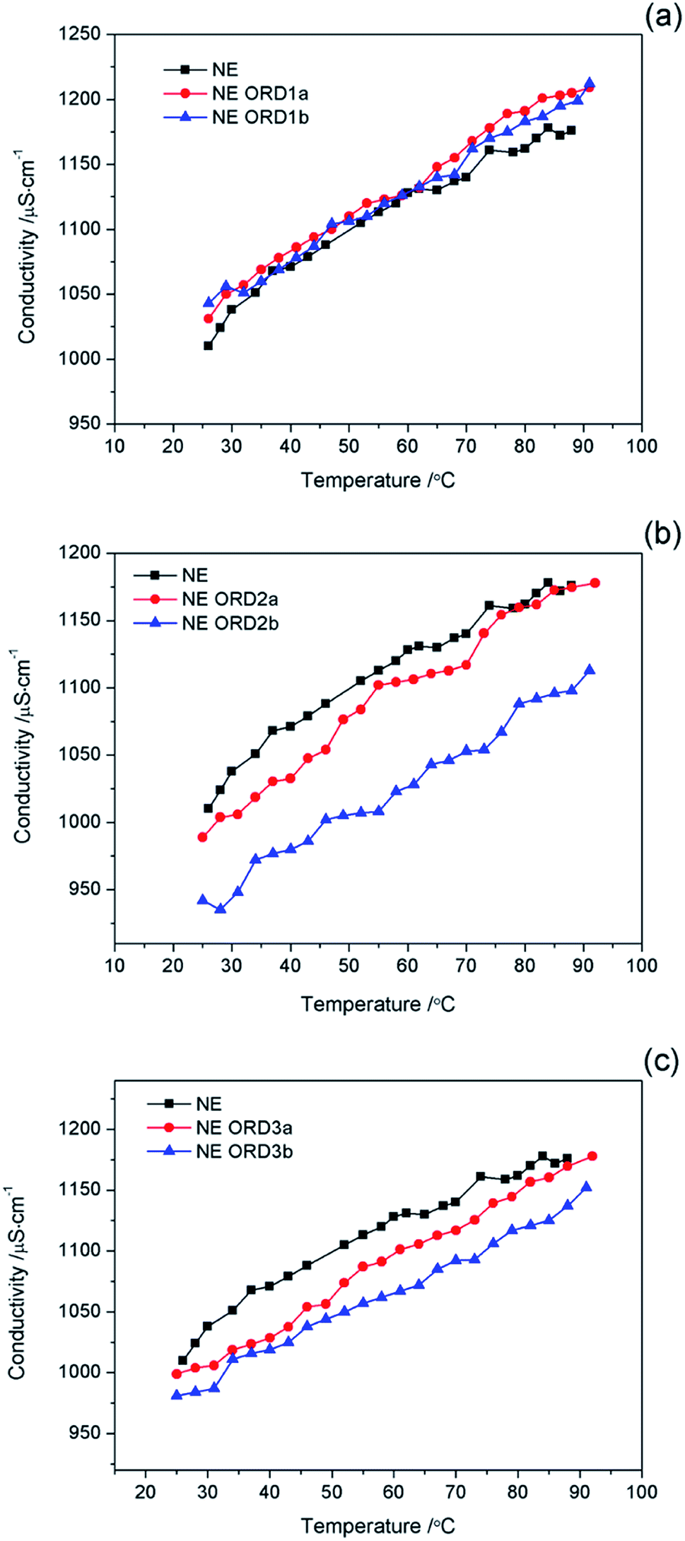
The relationship between the conductivity of the NE and temperature is shown in Fig. 7. In all cases, the conductivity increases as the temperature increased, which was due to the increase in the thermal motion of the particles. There was no abrupt transition in the conductivity during the heating process (25–92 °C), which indicates that no phase transitions occurred. The results also show that the emulsion possessed good temperature resistance.
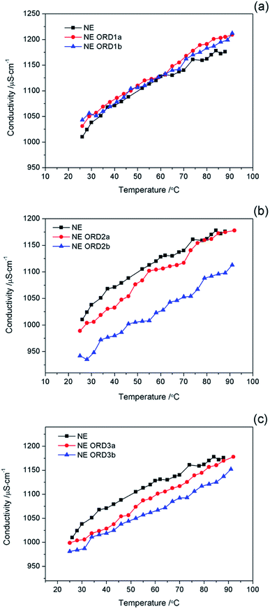 |
| | Fig. 7 Conductivity value of nanoemulsions with (a) ORD1, and (b) ORD2 and ORD3 at different ORD loadings as a function of temperature. | |
The change in the size of the NE particles over time is shown in Fig. 8. The particle size distribution changed little after standing for 30 days, which indicates that the NE had good long-term stability. Some layer particles might be dispersed in the aqueous or oil phases, except for the oil/water interface. When left for a long time, interactions between particles or between particles and the emulsion droplets might affect the average particle size and distribution of the emulsion.
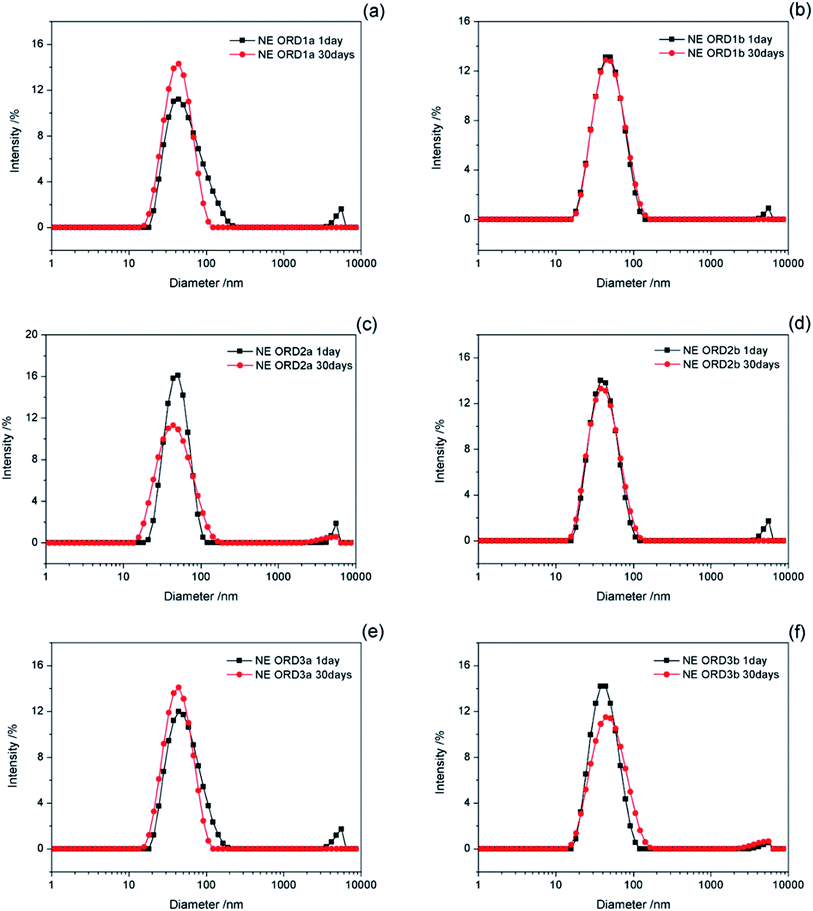 |
| | Fig. 8 Diameter variation of NEs storing for 1 and 30 days. | |
3.6. Core flooding experiment
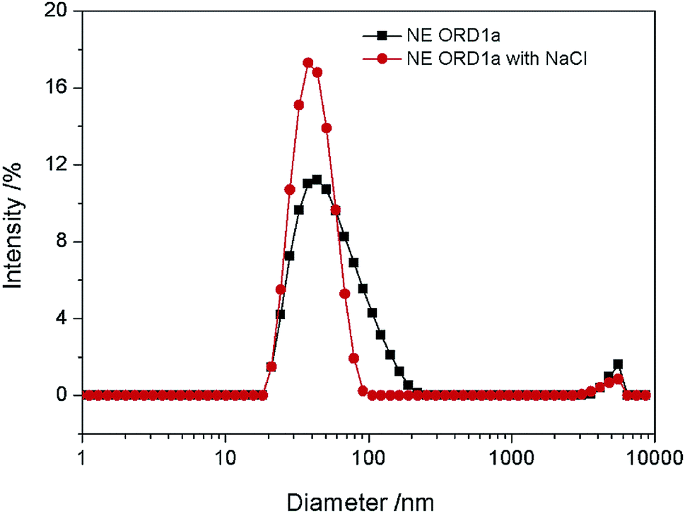
The EOR performance was evaluated using a core flooding experiment. The NE containing ORD1 formulation was selected to further study according to above research. Considering the practicalities of its application, the NE was prepared using 0.02 M of NaCl solution instead of distilled water, and it was diluted five times before displacement. As shown in the Fig. 9, the average particle size of the NE did not change significantly after preparation with NaCl aqueous solution and dilution. The average diameter of the NE droplets decreased from 55.1 to 40.77 nm after dilution, which was more favorable for transportation into the pores. As shown in Fig. 10, the IFT increased from 2.4 to 4.7 mN m−1 after dilution. The zeta potential value changed from −18.3 to −13.1 mV due to dilution. The change of IFT and zeta potential may result from the decreasing of surfactant concentration of NE. Overall, the NE properties did not change substantially.
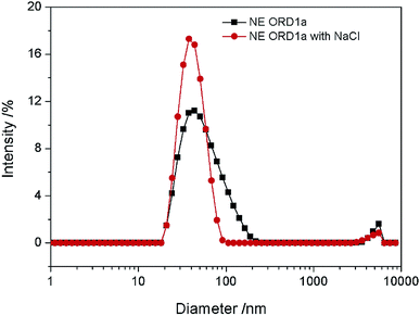 |
| | Fig. 9 Particle size distribution of NE ORD1a and NE ORD1a diluted with NaCl aqueous solution. | |
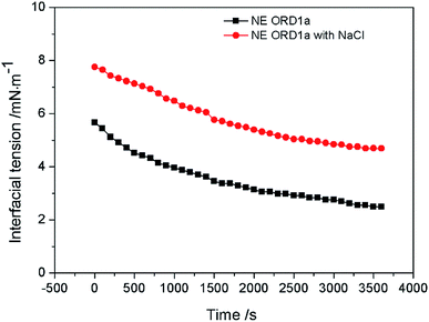 |
| | Fig. 10 Interface tension of NE ORD1a and NE ORD1a diluted with NaCl aqueous solution. | |
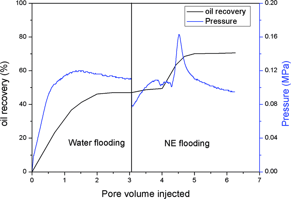
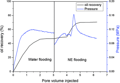
The gas permeability of the artificial sandstone core was 209 mD and the pore volume was 4.88 mL. The pressure difference and accumulated oil recovery curves for the core are presented in Fig. 11. The pressure difference decreased slightly and then gradually increased as the NE was injected into the core. The curves show that the accumulated oil recovery increased rapidly as the pressure difference changed. The oil recovery from water flooding was 47.06%, which increased to 70.59% for NE flooding. Thus, oil recovery was significantly enhanced by approximately 23.53%.
 |
| | Fig. 11 Core flooding experiment of NE flooding. | |
4. Conclusion
A nanoemulsion was successfully prepared using an amphiphilic copolymer, Brij30, and modified LAPONITE® RD as co-emulsifiers through phase inversion composition (PIC) method. The NE possessed good long-term and thermal stability. The appearance of NE was translucence and the droplets were less than 60 nm in diameter. The absolute value of the zeta potential of the NE increased when modified LAPONITE® RD was added, and the average particle size and PDI first increased and then decreased. The recovery of crude oil was significantly increased by 23.53% compared with water flooding when the NE was used in an EOR test with an artificial sandstone core. Therefore, the approach presented in this study is promising for EOR.
Conflicts of interest
There are no conflicts to declare.
Acknowledgements
This work was financially supported by the National Natural Science Foundation of China (grant no. 51674270; 51974339), National Major Project (grant no. 2017ZX05009-003) and Major project of the National Natural Science Foundation of China (grant no. 51490650).
References
- S. Thomas, Oil Gas Sci. Technol., 2008, 63, 9–19 CrossRef CAS.
- A. A. Olajire, Energy, 2014, 77, 963–982 CrossRef CAS.
- U. K. Bhui, S. Sanyal, R. Saha, S. Rakshit and S. K. Pal, Fuel, 2018, 234, 1081–1088 CrossRef CAS.
- J. Lu, P. J. Liyanage, S. Solairaj, S. Adkins, G. P. Arachchilage, D. H. Kim, C. Britton, U. Weerasooriya and G. A. Pope, J. Pet. Sci. Eng., 2014, 120, 94–101 CrossRef CAS.
- H. H. Pei, G. C. Zhang, J. J. Ge, M. G. Tang and Y. F. Zheng, Energy Fuels, 2012, 26, 2911–2919 CrossRef CAS.
- N. Pal, N. Saxena and A. Mandal, J. Pet. Sci. Eng., 2018, 168, 283–300 CrossRef CAS.
- M. S. Alnarabiji and M. M. Husein, Fuel, 2020, 267, 117262 CrossRef CAS.
- X. F. Sun, Y. Y. Zhang, G. P. Chen and Z. Y. Gai, Energies, 2017, 10, 345 CrossRef.
- B. L. Peng, L. C. Zhang, J. H. Luo, P. M. Wang, B. Ding, M. X. Zeng and Z. D. Cheng, RSC Adv., 2017, 7, 32246–32254 RSC.
- J. Giraldo, P. Benjumea, S. Lopera, F. Cortés and M. Ruiz, Energy Fuels, 2013, 27, 3659–3665 CrossRef CAS.
- S. Al-Anssari, S. B. Wang, A. Barifcani, M. Lebedev and S. Iglauer, Fuel, 2017, 206, 34–42 CrossRef CAS.
- E. Amott, Transactions of the AIME, 1959, 216, 156–162 CrossRef.
- M. Parvazdavani, M. Masihi and M. H. Ghazanfari, J. Pet. Sci. Eng., 2014, 124, 222–231 CrossRef CAS.
- H. Zhang, A. Nikolov and D. Wasan, Energy Fuels, 2014, 28, 3002–3009 CrossRef CAS.
- L. Hendraningrat, S. D. Li and O. Torster, J. Pet. Sci. Eng., 2013, 111, 128–138 CrossRef CAS.
- T. Lu, Z. M. Li, Y. Zhou and C. Zhang, Energy Fuels, 2017, 31, 5612–5621 CrossRef CAS.
- M. Zargartalebi, R. Kharrat and N. Barati, Fuel, 2015, 143, 21–27 CrossRef CAS.
- Z. Ahmad, P. Le, T. Kashiwao and A. Bahadori, Pet. Sci. Technol., 2016, 34, 1048–1054 CrossRef.
- K. Yang-Chuan, W. Guang-Yao and W. Yi, Eur. Polym. J., 2008, 44, 2448–2457 CrossRef.
- X. Hu, Y. C. Ke, Y. Zhao, C. C. Yu, S. C. Lu and F. F. Peng, RSC Adv., 2018, 8, 30491–30501 RSC.
- X. Hu, Y. C. Ke, Y. Zhao, S. C. Lu, C. C. Yu and F. F. Peng, Colloids Surf., A, 2018, 548, 10–18 CrossRef CAS.
- J. Cao, T. Song, Y. J. Zhu, X. J. Wang, S. S. Wang, J. C. Yu, Y. Ba and J. Zhang, RSC Adv., 2018, 8, 38056–38064 RSC.
- R. Zolfaghari, A. A. Katbab, J. Nabavizadeh, R. Y. Tabasi and M. H. Nejad, J. Appl. Polym. Sci., 2006, 100, 2096–2103 CrossRef CAS.
- A. Rezaei, M. Abdi-Khangah, A. Mohebbi, A. Tatar and A. H. Mohammadi, J. Mol. Liq., 2016, 222, 1148–1156 CrossRef CAS.
- L. F. Chen, X. M. Zhu, L. Wang, H. Yang, D. G. Wang and M. L. Fu, Energy Fuels, 2018, 32, 11269–11278 CrossRef CAS.
- Y. H. Lyu, C. L. Gu, J. P. Tao, X. Yao, G. Zhao and C. L. Dai, J. Mater. Sci., 2019, 54, 14752–14762 CrossRef CAS.
- H. Son, H. Kim, G. Lee, J. Kim and W. Sung, Korean J. Chem. Eng., 2014, 31, 338–342 CrossRef CAS.
- N. Kumar, T. Gaur and A. Mandal, J. Ind. Eng. Chem., 2017, 54, 304–315 CrossRef CAS.
- B. Wei, J. Ning, R. X. Mao, Y. Y. Wang, X. G. Xu and M. X. Bai, Soft Matter, 2019, 15, 4026–4034 RSC.
- Z. Li, B. J. Bai, D. R. Xu, Z. Y. Meng, T. Ma, C. B. Gou, K. Gao, R. X. Sun, H. R. Wu, J. R. Hou and W. L. Kang, Energy Fuels, 2019, 33, 81–88 CrossRef CAS.
- S. M. Jafari and D. J. McClements, Nanoemulsions: Formulation, Applications, and Characterization, 2018 Search PubMed.
- A. Gupta, H. B. Eral, T. A. Hatton and P. S. Doyle, Soft Matter, 2016, 12, 2826–2841 RSC.
- A. Perazzo, V. Preziosi and S. Guido, Adv. Colloid Interface Sci., 2015, 222, 581–599 CrossRef CAS.
- C. Solans and I. Sole, Curr. Opin. Colloid Interface Sci., 2012, 17, 246–254 CrossRef CAS.
- L. J. Wang, K. J. Mutch, J. Eastoe, R. K. Heenan and J. F. Dong, Langmuir, 2008, 24, 6092–6099 CrossRef CAS.
- I. Sole, A. Maestro, C. Gonzalez, C. Solans and J. M. Gutierrez, Langmuir, 2006, 22, 8326–8332 CrossRef CAS.
- N. Kumar and A. Mandal, J. Mol. Liq., 2018, 266, 147–159 CrossRef CAS.
- N. Kumar and A. Mandal, Energy Fuels, 2018, 32, 6452–6466 CrossRef CAS.
- N. Kumar and A. Mandal, Eur. Polym. J., 2018, 109, 265–276 CrossRef CAS.
- N. Pal, N. Kumar, R. K. Saw and A. Mandal, J. Pet. Sci. Eng., 2019, 183, 106464 CrossRef CAS.
- N. Pal, N. Kumar and A. Mandal, Langmuir, 2019, 35, 2655–2667 CrossRef CAS.
- N. Kumar and A. Mandal, Colloids Surf., A, 2020, 601, 125043 CrossRef CAS.
- N. Pal and A. Mandal, Fuel, 2020, 276, 118138 CrossRef CAS.
- D. N. Zhang, X. Du, X. M. Song, H. Z. Wang, X. L. Li, Y. W. Jiang and M. Y. Wang, SPE J., 2018, 23, 831–840 CrossRef CAS.
- M. Jalilian, A. Tabzar, V. Ghasemi, O. Mohammadzadeh, P. Pourafshary, N. Rezaei and S. Zendehboudi, Fuel, 2019, 251, 754–762 CrossRef CAS.
- F. F. Peng, Y. C. Ke, S. C. Lu, Y. Zhao, X. Hu and Q. C. Deng, RSC Adv., 2019, 9, 14692–14700 RSC.
|
| This journal is © The Royal Society of Chemistry 2021 |
Click here to see how this site uses Cookies. View our privacy policy here. 
 Open Access Article
 This Open Access Article is licensed under a Creative Commons Attribution-Non Commercial 3.0 Unported Licence
 *
*