
 Open Access Article
 This Open Access Article is licensed under a Creative Commons Attribution-Non Commercial 3.0 Unported Licence
The role of synthetic oils in controlling hydrogen permeation of rolling/sliding contacts
Hiroyoshi Tanaka ab,
Monica Ratoi*c and
Joichi Sugimurabd
ab,
Monica Ratoi*c and
Joichi Sugimurabd
aDepartment of Mechanical Engineering, Kyushu University, 744 Motooka, Nishi-ku, Fukuoka 819-0395, Japan
bResearch Centre for Hydrogen Industrial Use and Storage, Kyushu University, 744 Motooka, Nishi-ku, Fukuoka 819-0395, Japan
cFaculty of Engineering and Environment, University of Southampton, Southampton, UK. E-mail: m.ratoi@soton.ac.uk
dInternational Institute for Carbon-Neutral Energy Research, Kyushu University, 744 Motooka, Nishi-ku, Fukuoka 819-0395, Japan
First published on 24th December 2020
Abstract
Bearing steels suffer from degradation of mechanical properties when atomic hydrogen diffuses into the steel from the contact surface. In rolling contact fatigue tests this can lead to a significant reduction in fatigue life of the specimens as the amount of hydrogen diffused into the steel increases. To mitigate this challenge, synthetic oils of different chemistry have been studied so as to identify their efficiency and mechanism of retarding or preventing hydrogen permeation. Thrust bearing type tests were conducted with three synthetic base oils. The effect of base oil chemistry on hydrogen generation and permeation in bearing steel was explored by relating the concentration of hydrogen species in specimens with changes in the surface and subsurface of the wear track and the condition of the oil.
1. Introduction
The current search for sustainable engineering in the fields of energy, materials, transportation and manufacturing requires lubricating solutions which can solve new and complex challenges. Bearings used in applications such as hydrogen fuel cells, wind turbine gearboxes, automotive applications etc. experience demanding operating conditions (higher rotation speed, temperature, vibrations etc.) that lead to a shortening of their service life due to an unusual premature failure damage. This differs from the classic RCF described by ISO 15243 and consists in the appearance of a peculiar type of white etching area (WEA) associated with cracks (WEC).1,2It is believed that one of the main causes for WEAs is hydrogen which in its atomic form can readily diffuse through the lattice of solid materials and cause embrittlement i.e. degradation in high strength steels, and lead to catastrophic failure. In fuel cells that use hydrogen as a source of energy, hydrogen-assisted fatigue can result in formation of WECs and/or accelerate classic RCF3–11 and therefore represents an extra challenge for tribological parts.
In the high-stress, high-temperature conditions encountered in these applications both the environment (i.e. hydrogen gas in fuel cells, water vapors in air) and lubricant molecules (hydrocarbon oil and solubilized water) can decompose on the fresh, nascent, metal sites generated on the wear tracks and create atomic hydrogen.3,9,12–17 Severe lubrication conditions may produce more activated sites and increase hydrogen generation and diffusion in steel. In a hydrogen atmosphere, the amount of hydrogen diffused into the steel has been shown to be directly related to the reduction in service life.18–20 It is also reported that high-operating temperatures generate increased concentrations of hydrogen and consequently some research studies recommended that the lubricant temperature in wind turbine gearboxes which tend to overheat should be maintained below 75–90 °C to reduce hydrogen permeation and extend bearing life.
Hydrogen permeation can be prevented through the presence of a protective film on the wear track. The thin oxide film which normally covers steel surfaces is swiftly removed during operation and nascent metal sites are generated. One of the advantages offered by lubricants is their ability to continuously generate protective tribofilms on the wear track which can both, prevent wear and thus atomic hydrogen formation on the nascent steel surfaces and act as a barrier to hydrogen permeation.21
A previous study which investigated the effectiveness of a range of oils to generated hydrogen in vacuum conducted ball-on-disc sliding tests found that the amount of hydrogen was proportional to the wear width measured at the end of the test22 and therefore depends on the lubricity of the oil.
Thicker oxide layers generated in rolling contact fatigue tests lubricated with PAO in air atmosphere have been shown to reduce the amount of hydrogen diffused into the steel and significantly increase the fatigue lives.18
The presence of water and oxygen in the environment i.e. gas atmosphere and/or in the lubricant was shown to exert a significant effect on the tribofilm characteristics and the fatigue life in studies using dry and oil lubricated tests. In dry tests, a higher water concentration (95 ppm) increased the relative amount of Fe(OH)3 in the tribofilm and both water and oxygen increased the total wear rate and wear debris formation.23 A concentration of 100 ppm dissolved water in paraffinic hydrocarbon used to lubricate RCF tests led to a significant reduction (36–48% depending on the Hertzian contact pressure applied) in fatigue life.24
Despite hydrocarbon lubricants have been denounced as one of the main sources of atomic hydrogen, recent studies of RCF tests lubricated with PAO in air, hydrogen and argon atmospheres proved that air and hydrogen gas can enable the formation of tribofilms on the wear track and reduce the hydrogen content in steel.18,25 The tribofilm consisted of mainly solidified hydrocracked or oxy-polymerized carbon species and iron as oxides and elemental forms possibly generated through oil oxypolymerization (in air) and hydrocracking (in hydrogen) and its thickness decreased in the order Air > H2 > Ar.25
The chemistry of the hydrocarbon oils determines their physico-chemical properties such as polarity, water and air solubility, oxidation, thermal and hydrolytic stability etc. These characteristics are important not just to ensure efficient lubrication but also for their ability to generate tribofilms on the wear track through processes such as oxypolymerization and hydrocracking.25 This study aims to ascertain how the base oil chemistry influences lubrication performance, tribofilm characteristics and the changes in oil condition during testing in air. Thrust bearing type tests were conducted in air for up to ten hours using three types of synthetic oils selected to have similar viscosity but different chemistry.
2. Materials and methods
Three types of synthetic base oils, summarised in Table 1 were selected to lubricate the RCF tests: a polyalphaolefin (PAO32), a polyol ester – trimethyolpropane ester (POE) and a polypropylene glycol (PPG). The three oils have similar viscosities at the testing temperature (120 °C) but different chemical structures. From the lubrication viewpoint, the similarity in viscosity values will ensure similar film thicknesses in the EHD regime. The tests were carried out in mixed lubrication which is a combination of EHD and boundary and is governed by both the physical properties of the lubricant (EHL) and the chemical ones (boundary).26 The different chemistry of the oils confers distinct physicochemical properties such as polarity, thermal conductivity, specific heat, thermal and oxidative stability.26 Base oils characterized by high polarity (affinity for metal oxide surfaces) such as polyglycols and polyesters have a greater tendency to form coherent chemisorbed or physiosorbed layers and reduce boundary friction (and wear if the film is strong and thick enough), than less polar fluids such as PAOs. The thermal conductivity and specific heat properties are important in removing heat by conduction and convection, thus preventing overheating and the thermal and oxidative degradation of the hydrocarbon oil which can result in release of atomic hydrogen. In general, POE and PAO oils are more resistant to oxidation than PPG while POE and PPG have superior thermal stability properties than PAO. The thermal diffusivity of the oil defined as the its ability to conduct heat and calculated as thermal conductivity divided by density and specific heat capacity, varies in the order POE > PAO > PPG.26| POE | PPG | PAO | |
|---|---|---|---|
| Density g cm−3 | 0.993 | 0.991 | 0.826 |
| Viscosity at 40 °C cSt | 24.5 | 32.3 | 28.8 |
| Viscosity at 100 °C cSt | 5.1 | 7.6 | 5.6 |
| Film parameter Λ | 2.26 | 2.26 | 1.99 |
Tribological tests were carried out in a ball-on-disc tribometer. Fig. 1 shows a schematic illustration of the test rig and Table 2 summarizes the test conditions. Trust bearings were modified to contain only six balls (6.35 mm diameter) separated by a retainer. The balls were placed between a grooved top ring as a guide ring for the ball movement and a reversed lower ring with the flat surface in contact with the balls, finished as described below. The ball and disc steel is JIS SUJ2, equivalent to AISI 52100. An Rq (root mean square roughness) of 0.005 μm was achieved for the disc surface by grinding with silicon carbide paper followed by buff polishing with a 3 μm diamond slurry. The specimens were ultrasonically cleaned with hexane and acetone prior to the rolling contact tests.
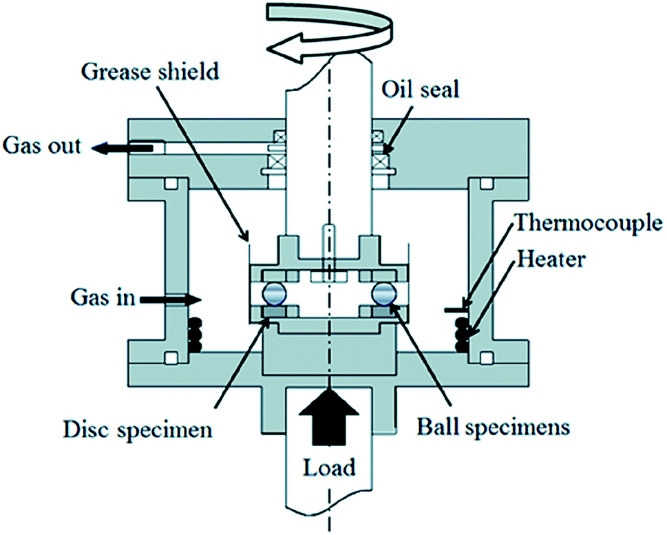 | ||
| Fig. 1 RCF tribometer. | ||
| Temperature | 120 °C |
| Hertzian pressure | 4.8 GPa |
| Entrainment speed | 1500 rpm (3.4 m s−1) |
| Initial composite surface roughness | 11 nm |
| Film parameter Λ | 2 |
| Test gas | Air |
| Lubricant | POE/PPG/PAO |
| Specimens | JIS SUJ2 steel balls/discs, Rq 10/5 nm |
A normal load of 2650 N (equivalent to a Hertzian pressure of 4.8 GPa between balls and flat disc and approximately 2.6 GPa between groove and balls) is applied by a lever and the disc/ball contact undergoes rolling through the rotation of the upper shaft. This contact pressure is higher than the calculated pressure encountered during standard operation in bearings and it follows the recommendations from other publications3,9,12,18–20 to accelerate wear, the formation of hydrogen and initiation of embrittlement. The Hertzian pressure employed of 4.8 GPa is almost equal to the shakedown limit (the maximum contact pressure which the material can support in the elastic range in steady state conditions) which implies that plastic deformation below the surface may continue to occur. In practice however, the pressure reduces due to the surface geometry changes which becomes more conformal through initial deformation and wear, and virtually elastic contact occurs in the rest of the test. The Hertzian contact pressure for the dynamic load rating (load for a rating life of 106 load cycles) of this steel is 4.2 GPa. The film parameter Λ which represents the ratio between the oil minimum film thickness (h) and the surface roughness (σ) has a value of 2 and thus the contact works in the mixed lubrication regime.
The balls were immersed in the oil lubricant before the test was started and no additional oil was supplied during the tests. Dry compressed air was continuously blown in at a rate of 100 ml min−1. Four RCF tests were carried out lasting 1, 2, 5 and 10 hours and these were considered to show appropriate trends in the behavior of the three lubricants.
The hydrogen content in the bearing steel discs was measured by Thermal Desorption Spectroscopy (TDS, Denshi-Kagaku TDS1200). Immediately after the rolling contact tests, the specimens were cooled to ambient temperature (23 °C), cleaned with hexane and acetone in an ultrasonic bath and the disc cut into small pieces (7 × 3.5 × 1 mm, weighing approximately 0.2 g) in less than two hours. The TDS technique consists of heating the sample under a constant temperature gradient in order to induce desorption of all gaseous species, which are then analysed by a mass spectrometer. During the TDS analysis, the cut disc pieces were heated from ambient temperature to 800 °C at a rate of 60 °C min−1 and 10 °C min−1 respectively. This leads to the desorption of all hydrogen species released from the disc which are then measured and analysed with a quadrupole mass spectrometer.
The amount of hydrogen is calculated by integrating the hydrogen spectrum over temperature.
Wear track surface investigations were carried out by optical microscopy, SEM and optical profilometry after the 2, 5 and 10 hour RCF tests.
Wear scars were investigated under an Nikon Eclipse optical microscope to characterise surface defects, deposits and corrosion damage.
A Bruker ContourGT optical profilometer was used to generate a 3D surface profile of the wear track on the disc specimens after the RCF tests and investigate the depth and width of the wear tracks. The measured profiles of the disc wear track were used to calculate the wear loss volume. This involved the calculation of the area of the wear track profile using the trapezoid rule, followed by the use of the Archard equation27 for the determination of the wear loss volume.
Optical profilometry (Bruker ContourGT) was used to investigate the depth and morphology of the wear tracks on the disc specimens after each test. The equipment generates a 3D surface profile of the wear track that can be analysed with the supplied software. For each sample multiple surface profiles were measured and used to calculate average depth values.
Raman and Auger Electron Spectroscopy (AES) were used to investigate tribofilms formed after 10 hour RCF testing because these films were the most developed.
Auger electron spectrometry was carried out using JEOL JAMP 9500 F with a 10 keV electron beam. A 10 seconds ion sputtering was performed before the analysis to remove the contaminated layer on the surface of approximately 3 nm.
Raman spectrometer analysis was performed using a Thermo Fisher Scientific DXR Raman Microscope with an internal YAG 532 nm laser wavelength and about 1 mW output power. The laser source was focused on the sample through either a 10× or 100× objective to a spot diameter of 10 or 1 μm. The acquisition time for Raman spectra varied depending on the strength of the Raman signals, until a satisfactory signal to noise ratio was achieved.
Wear track subsurface investigation was also carried out on the 10 hour specimens. The presence of cracks and White Etching Areas (WEAs) was investigated by a ‘standard’ serial sectioning method and the sections were made at 50 μm intervals. The sectioning technique involved the use of an ATM-OPAL 410 for mounting samples in Bakelite prior to grinding/polishing with a Struers Tegra automatic polisher with interchangeable polishing platens. A Vickers hardness indent was used to indicate the depth removed. To reveal the microstructure, cross-sections were etched in Nital (98% methanol, 2% nitric acid) for 15 seconds according to ASM guidelines.28
The oil condition was monitored before and after the 2, 5 and 10 hour RCF tests by FTIR and Karl-Fischer water content analysis.
A FT-IR Nicolet iN Microscope and spectrometer has been used for the FTIR analysis.
The water content of the lubricants was measured by titrating samples with Karl-Fischer reagent.
3. Results and discussion
3.1 Condition monitoring of the base oil lubricants
The condition monitoring of the oil at the end of the RCF tests to reveal changes in chemical composition due to oil degradation (oxidation and oxypolymerization) and variations in the amount of solubilized water (water dissolved in oil is a facile source of atomic hydrogen), can provide important information not only about the contribution of the lubricant to atomic hydrogen generation but also on the role of water to tribofilm formation, wear and fatigue life.FTIR spectra of the three oils measured before (in their fresh state) and after the 2, 5 and 10 h tests are shown in Fig. 2 and 3. While the spectra for POE (Fig. 3b) did not indicate that substantial changes occurred during the tests, PAO and PPG spectra (Fig. 2a and 3) showed significant deterioration with test time. The FTIR spectra for PAO at the end of the 5 and 10 h RCF tests show the formation of an ester bond (peaks at 1750 cm−1) that indicates oxidative degradation of the oil. The PPG spectra showed the ester bond even in the fresh oil indicating a low structural resistance to oxidation. At the end of the 10 h test the FTIR analysis revealed irreversible changes visually identified in Fig. 3b as two insoluble phases with distinctly different chemistry. Phase 1 contained less ether and hydroxyl groups than the original oil while phase 2 had more.
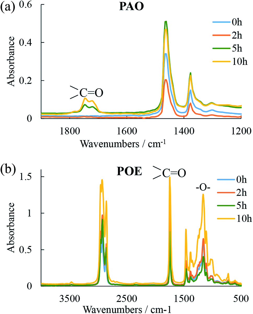 | ||
| Fig. 2 FT-IR spectra of (a) PAO and (b) POE after tests for 0, 2, 5 and 10 h. | ||
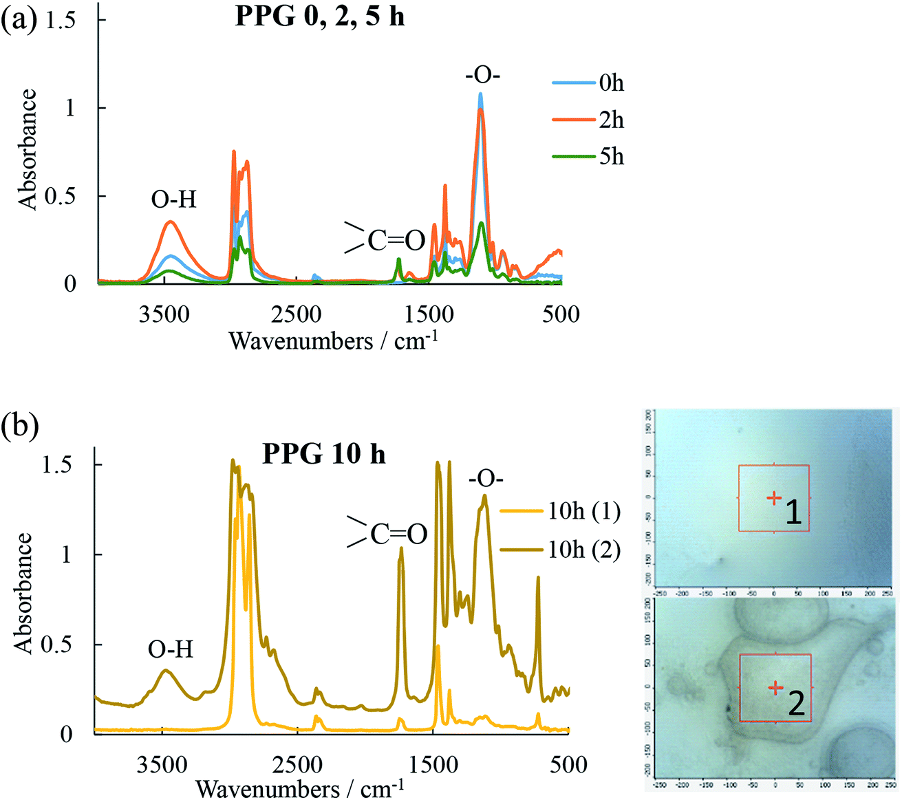 | ||
| Fig. 3 FT-IR spectra of PPG after (a) 0, 2, 5 h and (b) 10 h in locations 1 and 2. | ||
In RCF tests, three important factors responsible for the generation of free radicals and increase in the rate of oxidation are encountered: oxygen dissolved in the oil (from the continuous supply of air during the tests), high temperatures (tests are run at 120 °C and oxidation rate rises approximately three times per every 10 °C increase above ambient temperature) and the presence of metal ion catalysts (nascent iron surfaces generated on the wear track during the test). Excessive oxidation results in the formation of water (particularly in the propagation stage of the oxidative chain reaction), sludge and acids and the rate of oxidation determines the useful life of an oil lubricant. A good example of this was the phase segregation of the PPG oil seen at the end of the 10 h test.
The water solubilized in hydrocarbon oils and that from humid air (this study used dry compressed air) can also contribute to the overall water content. Water can be expected to dissolve in hydrocarbon oils to the extent of several hundred parts per million (ppm) and this amount increases with solvent polarity and temperature. The amount of water in the oils determined by Karl-Fischer titration before and at the end of the 1, 2, 5 and 10 hour RCF tests is shown in Table 3 and Fig. 4. In the fresh state, PPG contained the largest amount of solubilized water (three times more than POE) while PAO contained the least. The analysis at the end of the 10 h RCF tests revealed that except for POE, the other two oils (PPG and PAO) contained an increased amount of dissolved water. The water dissolved in oil is an easy source of atomic hydrogen and therefore, a high-water content can increase atomic hydrogen generation.
| 0 h | 1 h | 2 h | 5 h | 10 h | |
|---|---|---|---|---|---|
| POE | 317.4 | 166.2 | 186.3 | 254.6 | 229.1 |
| PPG | 899.6 | 836.1 | 1578.8 | 1405.9 | 973.8 |
| PAO | 13.8 | — | 42.1 | 187.9 | 479.4 |
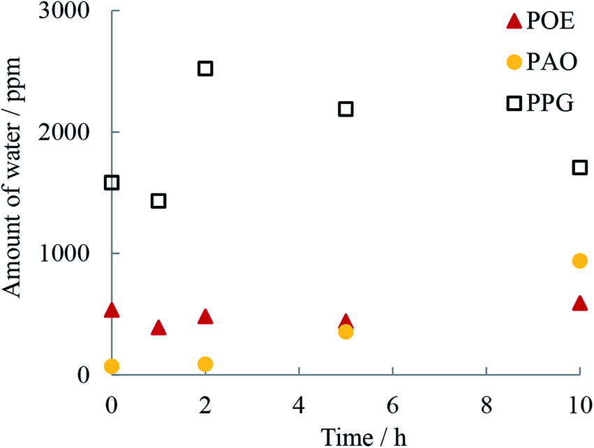 | ||
| Fig. 4 Water content (ppm) in oils from Karl-Fischer analysis before and after the 1, 2, 5 and 10 h of RCF testing. | ||
PAO contained a very low amount of water during the first two hours of testing but then the water increased quickly and after 10 h overtook the concentration found in POE. Because of its chemical structure POE has high resistance to oxidation but its polar groups can solubilize residual water from air. This can explain the relatively large concentration of water measured in the fresh POE oil. FTIR spectra for PPG show the presence of the ester peak in the fresh oil which indicates that the oil was slightly oxidized, and the large amount of water could be the product of its oxidation. Indeed, PAO and POE are characterized by very good oxidation stability, superior to PPG oils.26 Another contributing factor is the marked difference in the polarity of the oils. Both PPG and POE are polar oils which can solubilize significantly larger amounts of water than PAO which is a very low polarity oil.26
3.2 Amount of permeated hydrogen
As Table 4 and Fig. 5 shows, the concentrations of permeated hydrogen in the discs measured by TDS were lower for POE and PAO and did not substantially change with rolling time for these oils while for PPG the concentration increased with time.| 0 h | 1 h | 2 h | 5 h | 10 h | |
|---|---|---|---|---|---|
| POE | 0.274 | 0.152 | 0.225 | 0.163 | 0.295 |
| PPG | 0.274 | 0.282 | 0.216 | 0.458 | 0.302 |
| PAO | 0.274 | — | 0.229 | 0.2044 | 0.203 |
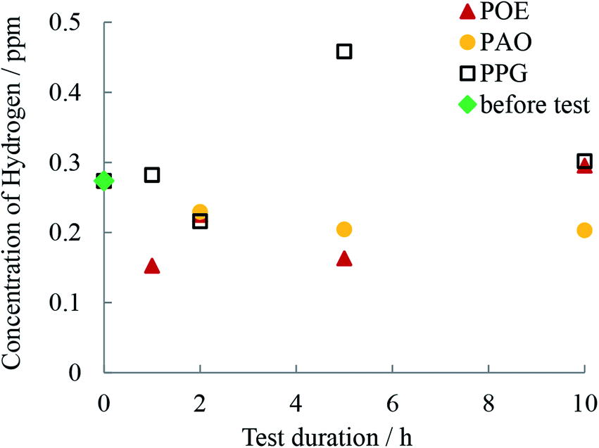 | ||
| Fig. 5 Hydrogen content in disc as measured by TDS before and after the 1, 2, 5 and 10 h of RCF testing. | ||
3.3 Wear track surface and subsurface investigation
To investigate the morphology and size (width and depth) of the wear track, optical profilometry has been employed. The profiles measured across the wear track were then used to calculate wear volume loss for each test. Fig. 6 compares the typical 2D profiles of the raceways as measured by optical profilometry at the end of the 2, 5 and 10 h tests and Fig. 7 shows the calculated wear volume loss.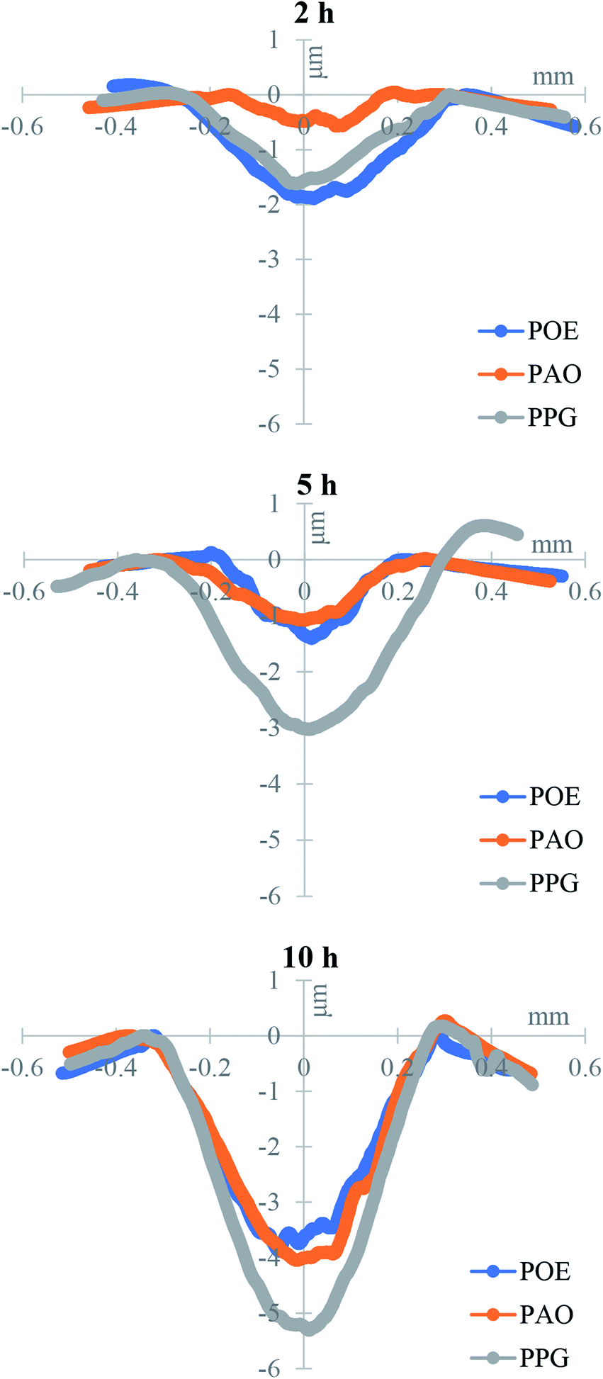 | ||
| Fig. 6 Profiles of disc wear tracks at 2, 5 and 10 h. | ||
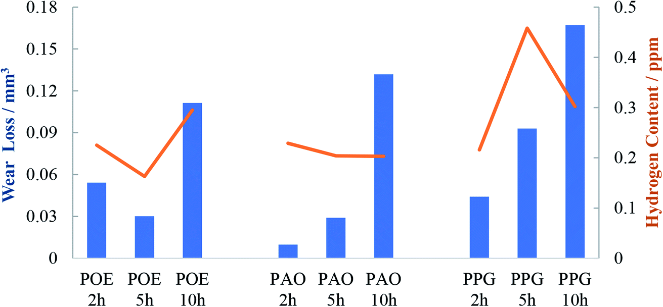 | ||
| Fig. 7 Wear volume loss of the disc wear track and the hydrogen content. | ||
As previously reported,29 during high load testing, the edges of the wear track become slightly raised due to plastic deformation and the height of the side ridges or furrows of the track usually do not change (unless there is additional pile-up due to wear). This situation was seen to similar degree in all specimens.
After 10 h testing the width of the track was similar for the three oils but the PPG lubricated wear track was significant deeper than the rest and the wear loss evolved more rapidly. After 10 h of continuous testing the wear loss varied in the order POE < PAO < PPG. This is also the order in which the content of hydrogen in the discs decreased (Fig. 2 and 7). For PPG this outcome can be related to the large amount of water formed/solubilized in the oil during the RCF tests which contributed to the wear through corrosion mechanisms while its decomposition led to an increased hydrogen content in the race.
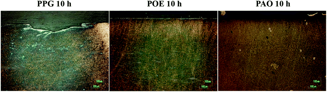
The wear tracks of the disc specimens were in the first stage investigated by optical microscopy and SEM as shown in Fig. 8 and 9. Images acquired by both techniques showed the presence of a tribofilm which formed gradually during the RCF testing with different kinetic rates. The PPG formed a tribofilm slowly (after about 5 h of testing) while the PAO formed a thin uniform tribofilm in under 2 h which became thicker after 5 h and developed an additional black film on the surface in 10 h of testing.
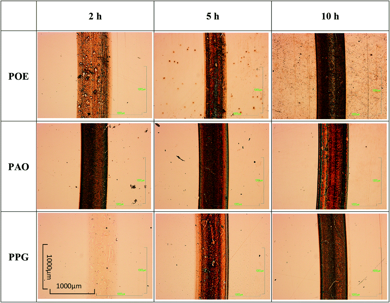 | ||
| Fig. 8 Optical microscope images of the disc wear tracks. | ||
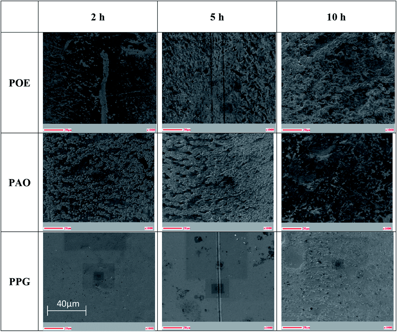 | ||
| Fig. 9 SEM images of the disc wear tracks. | ||
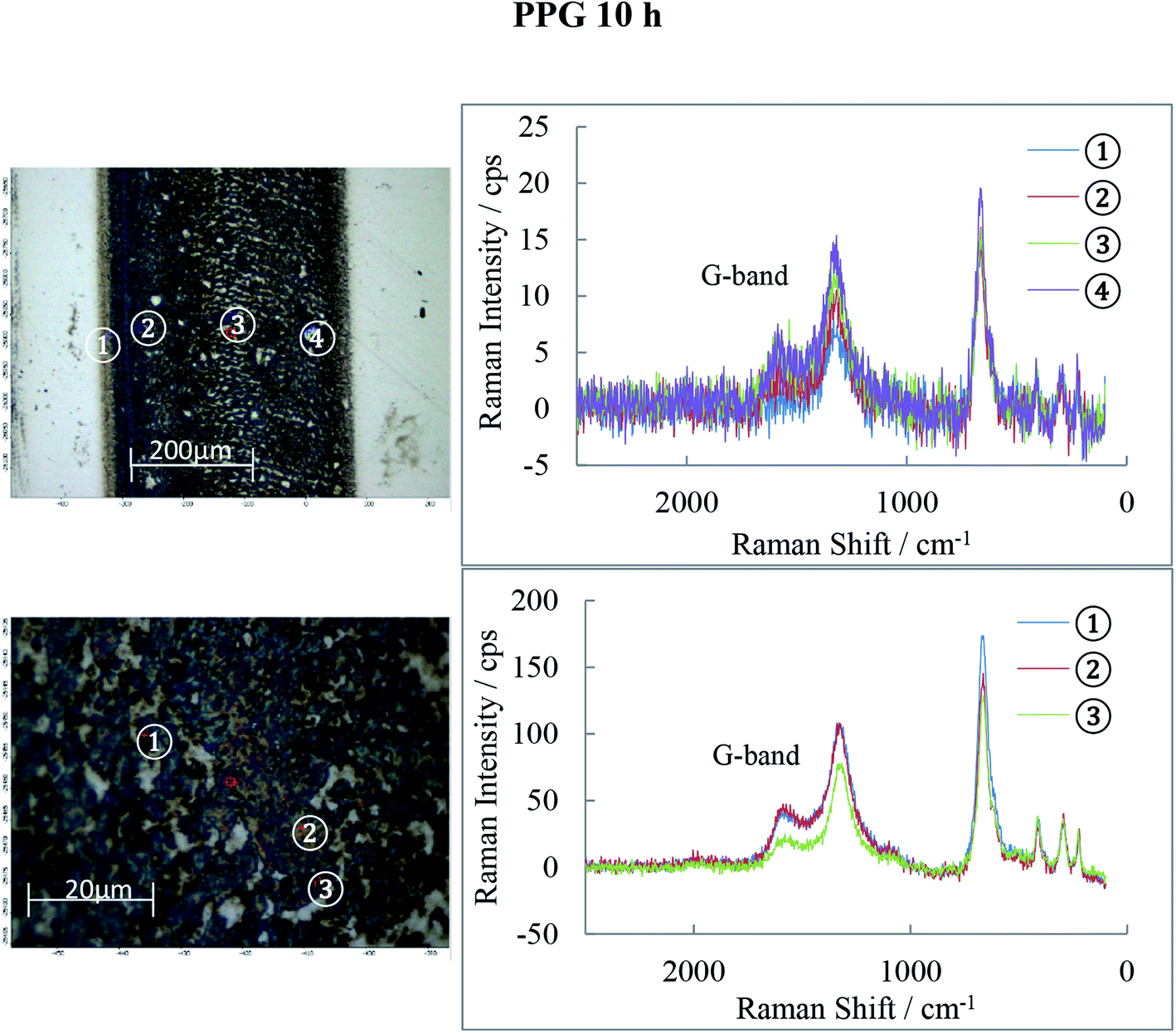
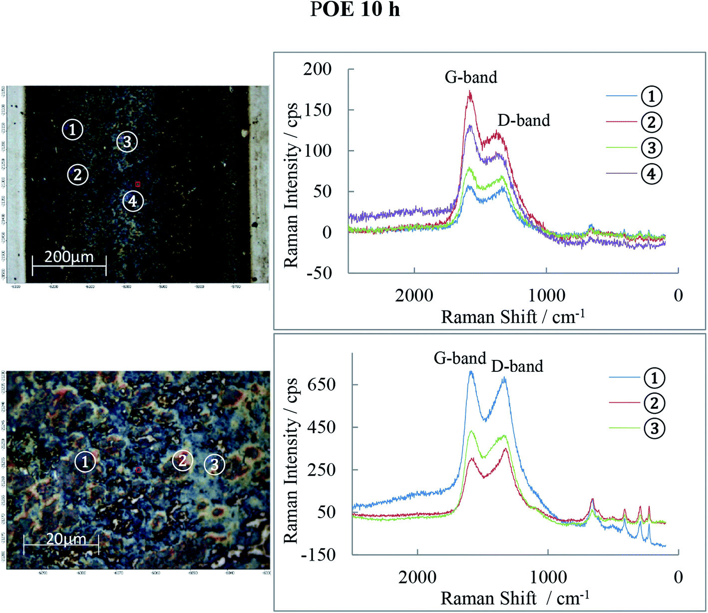
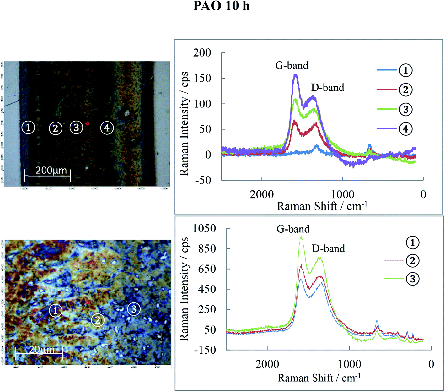
The nature of the tribofilms generated on the discs wear track during the RCF test was analyzed by Auger Electron Spectroscopy (AES) and Raman Spectroscopy.
The AES spectra for the 10 h test races, which had the most developed tribofilms was used to investigate the elemental distribution across the wear track and are shown in Fig. 10–12. The wear tracks were observed by SEM to have two areas of significantly different darkness (marked as 1 and 2 on SEM images in Fig. 10–12) and these areas were selected for the AES analysis. The AES spectra show peaks for iron, oxygen and carbon but of different intensities which indicates differences in the composition of the tribofilms. The black patches of the PAO tribofilms are mainly carbon, while the grey ones are predominantly iron oxide. The POE and PPG tribofilms are rich in both iron oxide and carbon but POE tribofilms contain significantly more carbon than iron oxide.
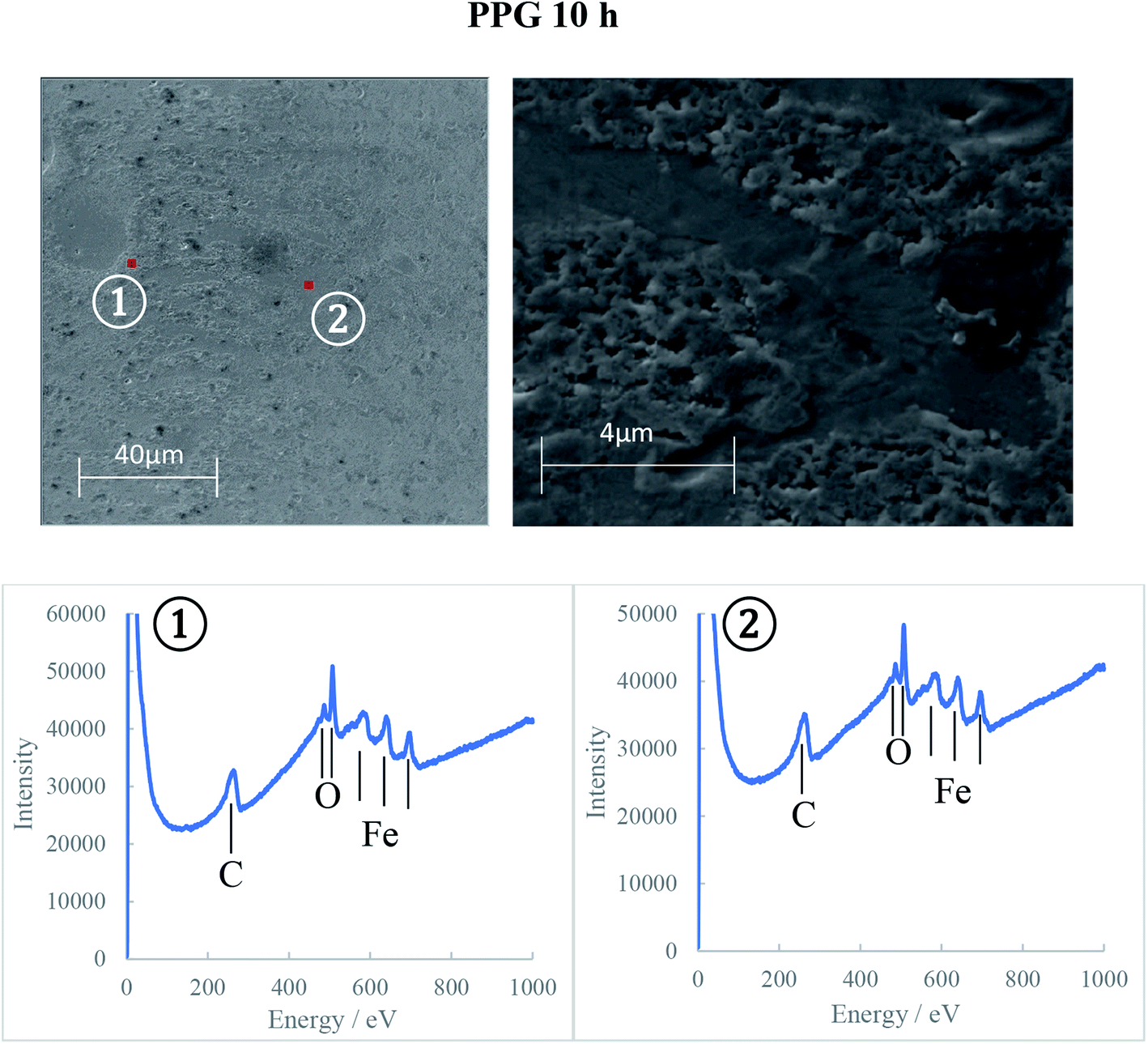 | ||
| Fig. 10 AES spectra on the 10 h PPG disc wear track. | ||
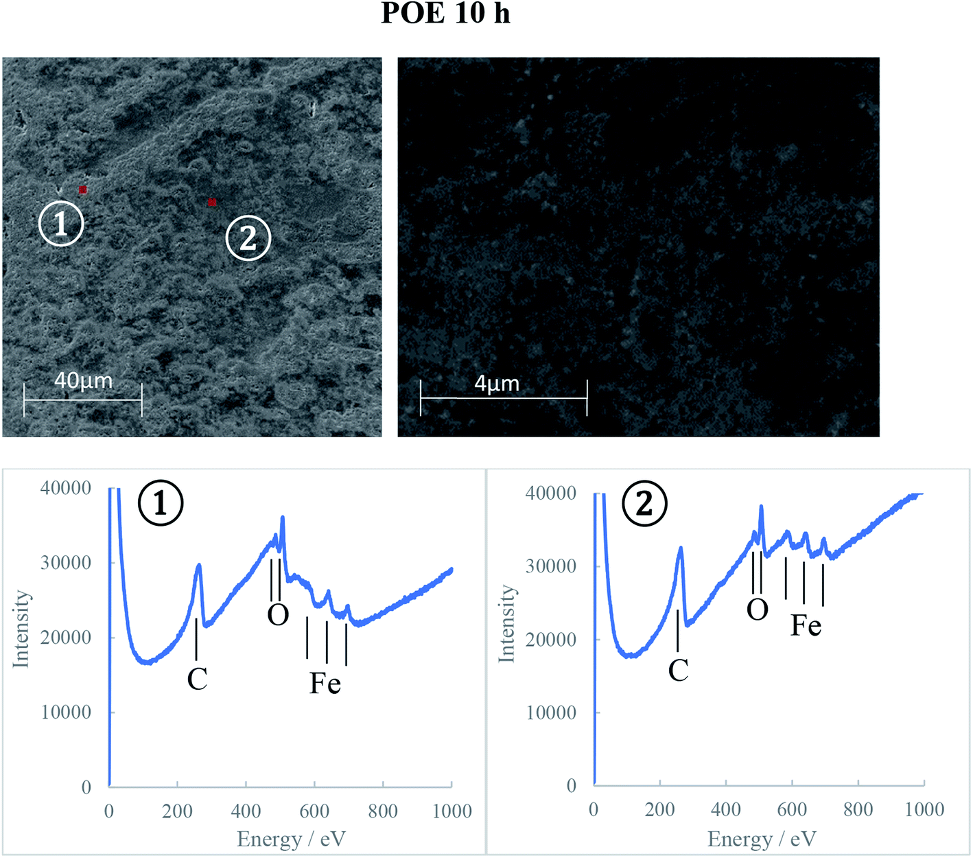 | ||
| Fig. 11 AES spectra on the 10 h POE disc wear track. | ||
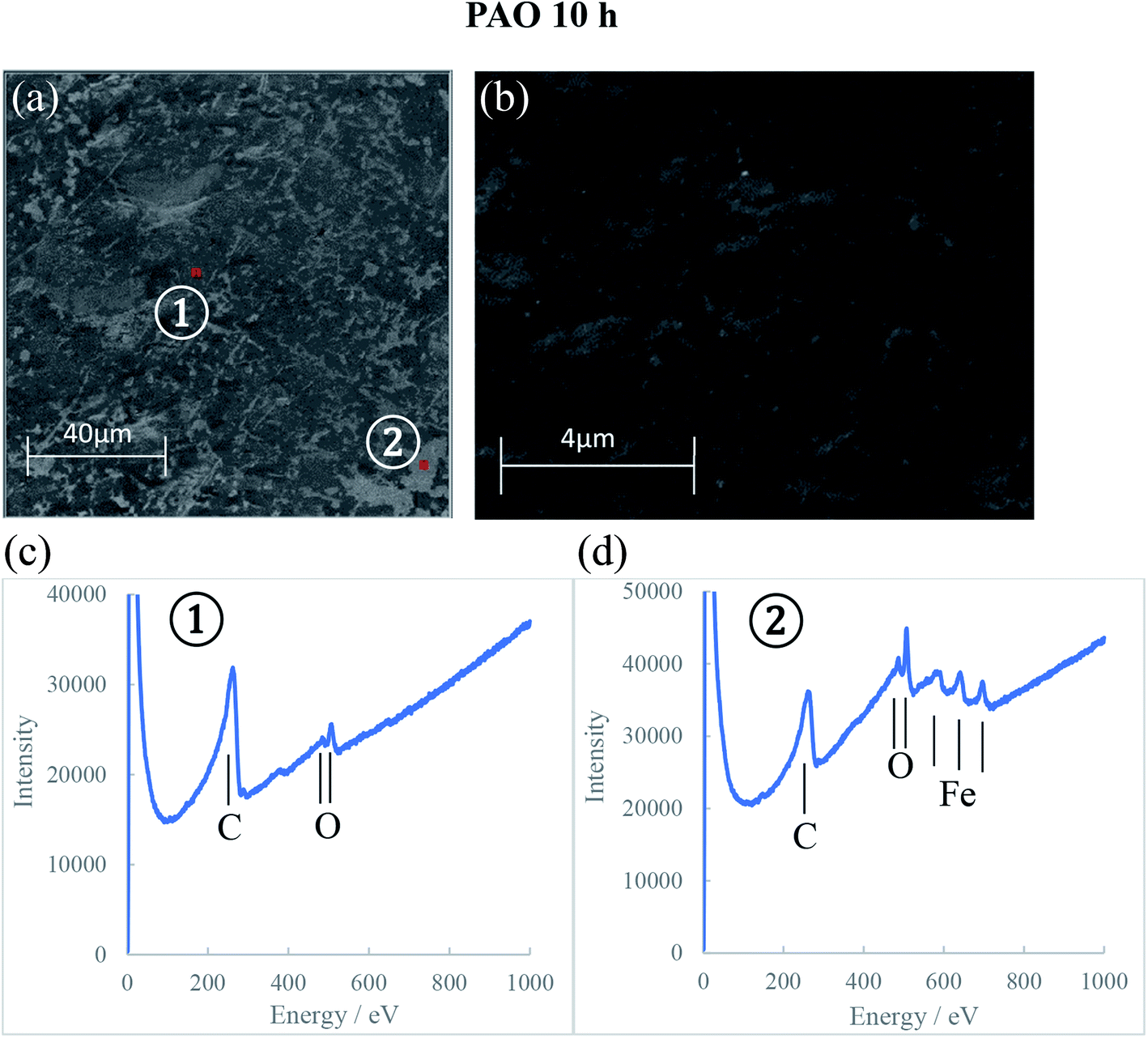 | ||
| Fig. 12 SEM images (a and b) and AES spectra (c and d) on the 10 h PAO disc wear track. | ||
AES analysis was also used to investigate the differences in the kinetics of tribofilm development for the three oils. The results confirmed the optical and SEM observations that the formation of an oxide film with PPG was slower compared to the other synthetic oils. Only a thin oxide film was generated during the first 5 hours of testing and it took up to 10 hours to grow to a thick oxide film. This behavior can explain the large amount of hydrogen permeated in the PPG discs during the 5 hours testing while the decrease in hydrogen concentration after that can be the result of iron oxide formation on the wear track and more hydrogen being desorbed than generated and absorbed. The formation of the tribofilm led to deactivation of the catalytic action of nascent steel surface, reduced wear and thus less atomic hydrogen permeation into the steel substrate. When inorganic carbon films additionally form on the track at an early stage of RCF testing as seen on PAO and POE tribofilms, hydrogen generation and permeation in steel could be further prevented.
Raman spectra of the 10 h tribofilms (Fig. 13–15) show that tracks were covered by iron oxide and carbon.
 | ||
| Fig. 13 Raman spectra for the PPG 10 h disc wear track. | ||
 | ||
| Fig. 14 Raman spectra for the POE 10 h disc wear track. | ||
 | ||
| Fig. 15 Raman spectra for the PAO 10 h disc wear track. | ||
Hematite (α-Fe2O3) is found in all three tribofilms with peaks at 226, 293, 413, 498 and 660 cm−1.30
The common features for carbon Raman spectra, the G and D peaks lie at ca. 1580 and 1360 cm−1. A single Raman peak is theoretically expected for the hexagonal lattice of graphite and has been observed around 1580 cm−1 in natural graphite and stress-annealed pyrolytic graphite. The Raman peak at 1360 cm−l has been shown to arise from graphite containing disorganized regions near crystal edges and lattice defects such as edge dislocations, lattice vacancies and interstitial carbon atoms between the basal planes of carbon atoms, sp2 bonded as in the graphite-crystal structure. The amorphous graphite exhibits a single broad asymmetric peak ranging from 1000 cm−1 to 1800 cm−1 and centred at about 1500 cm−1, while for Raman shifts <1000 cm−1, the amorphous graphite has an additional weak asymmetric peak around 730 cm−1. The Raman spectra of ball-milled graphite powder showed that both the 1360 cm−1 and 1580 cm−1 peaks of microcrystallite graphite broaden continuously with milling which generates amorphous carbon. Prolonged mechanical milling generates graphite with nanocrystalline phase and amorphous phase.31,32 This graphite has a similar Raman spectra pattern to that measured on the wear tracks of POE, PAO and PPG discs in this study which indicates that the rolling of balls on races can generate a graphite film consisting of nano/micro and amorphous phases.
The POE 10 h track is covered by both carbon and iron oxide while the PAO 10 h track shows even more carbon than POE. PPG 10 h shows much weaker D and G-bands (especially) and therefore low carbon content. The oxide film detected by AES is now identified to be Fe2O3 and it basically covers the entire track. The band intensities and their ratio are different from location to location on the wear track suggesting that the structure of the carbon films is not uniform.
The wear track subsurface in races was investigated using serial sectioning which revealed a small number of subsurface cracks as seen in Fig. 16a–c. The PPG lubricated wear track experienced flaking (Fig. 16a) and the serial sections also showed the presence of voids.
 | ||
| Fig. 16 Serial sections of the disc specimens revealing flaking in PPG 10 h disc. | ||
The flaking of the PPG track could be explained by the slow formation of the PPG tribofilm and increased wear. A similar situation was encountered when RCF tests were run in an inert argon atmosphere where oxypolymerization of the hydrocarbon lubricant cannot take place; the resultant tribofilm was thinner and contained less carbon and iron oxide. This situation led to extensive surface-initiated spalling and pitting and therefore reduced service life.
Hydrogen permeation in steel during RCF tests conducted in air environment depended on the synthetic oils ability to: (1) generate tribofilms on the wear tracks. The tribofilms took approximately 5 hours to develop fully. They were made up of iron oxides (hematite) and carbon (graphite with micro/nanocrystalline and amorphous phases) and formed under the influence of the oxygen (in the air environment), water (from oil and air), the high RCF testing temperatures and prolonged rolling contact. The tribofilms formation led to a decrease in the hydrogen content in discs afterwards. They reduce wear and thus prevent the formation of the catalytic nascent metal sites which generate atomic hydrogen by splitting up the hydrocarbon-based oils and water (i.e. in air and hydrocarbon oils); (2) possess very good oxidation and thermal stability. Both POE and PAO oils excel from this point of view and the results showed they are highly fit for purpose; (3) display little solubility for water (a low dissolved water content). PPG contained the highest amount of dissolved water and generated the largest content of hydrogen in the race.
4. Conclusions
The study revealed that base oil chemistry plays an important role in wear prevention and hydrogen permeation in bearings. These effects are influenced by the ability of the lubricant to generate tribofilms on the wear track while preserving its bulk chemical makeup and composition. The following conclusions that relate the synthetic oil chemistry to its performance in the RCF tests can be drawn: (1) the amount of hydrogen permeated into steel is relatively small with POE and PAO and it does not change with rolling time; (2) the chemical stability (oxidative and thermal degradation) of the synthetic oils during the RCF tests varied in the order POE > PAO > PPG; (3) hydrogen permeation depends on the amount of water solubilized in oils. PPG contained a relatively large amount of water and induced a higher concentration of hydrogen in steel; (4) all three synthetic oils generated tribofilms made up of iron oxide (hematite) along with micro/nanocrystalline and amorphous graphite. Thick carbon films cover the iron oxides in the tribofilms formed by PAO and POE while PPG films are mainly made of iron oxide; (5) the tribofilms reduced the wear rate and suppressed hydrogen generation and permeation in discs; (6) essentially, the amount of hydrogen permeated in the steel during rolling depends on the formation of tribofilms at contacting surface and on the water content in the oils. These important findings enable a better understanding of the complex lubrication challenges posed by the sustainable energy industry and help lubricant formulators to offer efficient solutions.Data availability
The raw/processed data required to reproduce these findings cannot be shared at this time due to technical and time limitations.Conflicts of interest
There are no conflicts to declare.Acknowledgements
The authors thank Taiho Kogyo Tribology Research Foundation for sponsoring this study and Mr Hiroki Fukuoka for carrying out some of the experimental tests used in this study.References
- M. Shibata, M. Gotoh, N. Oguma and T. Mikami, A new type of micro-structural change due to rolling contact fatigue on bearings for the engine auxiliary devices, Proceedings of the International Tribology Conference, 1995, vol. 3, pp. 1351–1356 Search PubMed.
- N. Mitamura, H. Hidaka and S. Takaki, Microstructural development in bearing steel during rolling contact fatigue, Mater. Sci. Forum, 2007, 539–543, 4255–4260 CAS.
- J. A. Ciruna and H. J. Szeileit, The effect of hydrogen on the rolling contact fatigue life of AISI 52100 and 440C steel balls, Wear, 1973, 24, 107–118 CrossRef CAS.
- H. K. Birnbaum and P. Sofronis, Hydrogen-enhanced localized plasticity-a mechanism for hydrogen-related fracture, Mater. Sci. Eng., A, 1994, 176, 191–202 CrossRef CAS.
- A. Grabulov, Fundamentals of rolling contact fatigue, PhD thesis, University of Belgrade, 2010.
- M. Evans, An updated review: white etching cracks (WECs) and axial cracks in wind turbine gearbox bearings, Mater. Sci. Technol., 2016, 1–37 Search PubMed.
- K. Stadler and A. Stubenrauch, Premature bearing failure in industrial gearboxes, Antriebstechnisches Kolloquium (ATK), Aachen, Germany, 2013 Search PubMed.
- A. Ruellan, F. Ville, X. Kleber, A. Arnaudon and D. Girodin, Understanding white etching cracks in rolling element bearings: the effect of hydrogen charging on the formation mechanisms, Proc. Inst. Mech. Eng., Part J, 2014, 228(11), 1252–1265 CrossRef CAS.
- H. Uyama, H. Yamada, H. Hidaka and N. Mitamura, The effects of hydrogen on microstructural change and surface originated flaking in rolling contact fatigue, Tribol. Online, 2011, 6(2), 123–132 CrossRef.
- H. Uyama and H. Yamada, White structure flaking in rolling bearings for wind turbine gearboxes, Wind Systems, 2014, http://www.windsystemsmag.com/article/detail/619/white-structure-flaking-in-rolling-bearings-for-wind-turbine-gearboxes, retrieved: October 2014 Search PubMed.
- H. Hamada and Y. Matsubara, The influence of hydrogen on tension-compression and rolling contact fatigue properties of bearing steel, NTN Technical Review, 2006, vol. 74, pp. 54–61 Search PubMed.
- M. Kohara, T. Kawamura and M. Egami, Study on mechanism of hydrogen generation from lubricants, Tribol. Trans., 2006, 49(1), 53–60 CrossRef CAS.
- R. Lu, H. Nanao, K. Kobayashi, T. Kubo and S. Mori, Effect of lubricant additives on tribochemical decomposition of hydrocarbon oil on nascent steel surfaces, J. Jpn. Pet. Inst., 2010, 53(1), 55–60 CrossRef CAS.
- S. Fujita, N. Mitamura and Y. Murakami, Research of new factors affecting rolling contact fatigue life, World Tribology Congress III, 2005 Search PubMed.
- K. Mizuhara, T. Taki and K. Yamanaka, Anomalous cracking of bearing balls under a liquid-butane environment, Tribol. Int., 1993, 26(20), 135–142 CrossRef CAS.
- N. Kino and K. Otani, The influence of hydrogen on rolling contact fatigue life and its improvement, JSAE Rev., 2003, 24, 289–294 CrossRef CAS.
- D. Ray, L. Vincent, B. Coquillet and P. Guirandenq, Hydrogen embrittlement in a stainless ball bearing steel, Wear, 1980, 65(1), 103–111 CrossRef CAS.
- H. Tanaka, T. Morofuji, K. Enami, M. Hashimoto and J. Sugimura, Effect of environmental gas on surface initiated rolling contact fatigue, Tribol. Online, 2013, 8(1), 90–96 CrossRef.
- H. Tanaka, M. Hashimoto, J. Sugimura and Y. Yamamoto, Rolling contact fatigue of bearing steel in hydrogen environment, World Tribology Congress III, 2005, vol. 1, pp. 155–156 Search PubMed.
- T. Otsu, H. Tanaka, K. Ohnishi and J. Sugimura, Simple experiment on permeation of hydrogen into steel in cyclic contact, Tribol. Online, 2011, 6(7), 311–316 CrossRef.
- H. Tanaka, V. Niste, Y. Abe and J. Sugimura, The effect of lubricant additives on hydrogen permeation under rolling contact, Tribol. Lett., 2017, 65–94 Search PubMed.
- M. Kohara, T. Kawamura and M. Egami, Study on mechanism of hydrogen generation from lubricants, Tribol. Trans., 2006, 49(1), 53–60 CrossRef CAS.
- K. Fukuda, Y. Kurono, N. Izumi and J. Sugimura, Influence of trace water and oxygen in a hydrogen environment on pure Fe friction and wear, Tribol. Online, 2010, 5(2), 80–86 CrossRef.
- P. Schatzberg and I. M. Felsen, Effects of water and oxygen during rolling contact lubrication, Wear, 1968, 12, 331–342 CrossRef CAS.
- M. Ratoi, H. Tanaka, Brian, G. Mellow and J. Sugimura, Hydrocarbon Luricants Can Control Hydrogen Embrittlement, Sci. Rep., 2020, 10, 1361 CrossRef CAS.
- Synthetics, Mineral Oils and Bio-Based Lubricants, ed. L. R. Rudnick, CRC Press, 2nd edn, 2013 Search PubMed.
- G. W. Stachowiak and A. W. Batchelor, Engineering Tribology, Elsevier Buterworth-Heinemann, 4th edn, 2014 Search PubMed.
- B. Bramfitt and A. Benscote, Common Etchants for Iron and Steels: Datasheet, in Metallographer's Guide: Practices and Procedures for Irons & Steels, ASM International, Materials Park, OH, 2001 Search PubMed.
- V. Niste, H. Tanaka, M. Ratoi and J. Sugimura, WS2 nanoadditized lubricant for applications affected by hydrogen embrittlement, RSC Adv., 2015, 5, 40678–49687 RSC.
- D. Bersani, P. P. Lottici and A. Montenero, Micro-Raman investigation of iron oxides films and powders produced by sol-gel syntheses, J. Raman Spectrosc., 1999, 30, 355–360 CrossRef CAS.
- T. D. Shen, W. Q. Ge and K. Y. Wang, Structural disorder and phase transformation in graphite produced by ball milling, Nanostruct. Mater., 1996, 7(4), 393–399 CrossRef CAS.
- P. K. Chu and L. Li, Characterization of amorphous and nanocrystalline carbon films, Mater. Chem. Phys., 2006, 96, 253–277 CrossRef CAS.
| This journal is © The Royal Society of Chemistry 2021 |