Rational strategies toward efficient and stable lead-free tin halide perovskite solar cells

Dongxu He a, Liang Shen *b, Yang Bai *a and Lianzhou Wang *ac
aAustralian Institute of Bioengineering and Nanotechnology, The University of Queensland, Brisbane, QLD 4072, Australia. E-mail: y.bai@uq.edu.au
bState Key Laboratory of Integrated Optoelectronics, College of Electronic Science and Engineering, Jilin University, 2699 Qianjin Street, Changchun 130012, People's Republic of China. E-mail: shenliang@jlu.edu.cn
cSchool of Chemical Engineering, The University of Queensland, Brisbane, QLD 4072, Australia. E-mail: l.wang@uq.edu.au

Received 30th November 2020 , Accepted 22nd March 2021

First published on 26th March 2021


Abstract

Despite the incredible progress of lead halide perovskite solar cells (LHPSCs), concerns remain regarding their potential impacts on the environment and human heath arising from their toxic and dissolvable lead content. Significant efforts have been devoted to searching lead-free halide perovskites over the past years. Among all these candidates, tin halide perovskites (THPs) have shown the most promise, where the efficiency of THP solar cells (THPSCs) has been progressing steadily. However, a considerable gap still exists between THPSCs and LHPSCs in terms of both efficiency and environmental stability. In this review, we first present a fundamental understanding of the origins of the inadequate efficiency and stability of THPSCs. Subsequently, a comprehensive and up-to-date overview focusing on the strategies addressing these issues facing THPSCs, including composition and dimension tuning, additive engineering and device engineering, is provided. Finally, we discuss the remaining challenges and give a perspective outlining the possible future directions for closing the gap between THPSCs and LHPSCs.
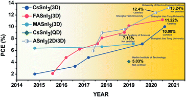

image file: d0qm01002b-p1.tif

Dongxu He

Dongxu He received his BE degree from The University of New South Wales in 2016 and received his MPhil degree in Chemical Engineering from The University of Queensland in 2019. He then continued his study as a PhD student in The University of Queensland under the supervision of Dr Yang Bai and Prof. Lianzhou Wang. Currently, Dongxu's research focuses on lead-less and lead free perovskite materials and their photovoltaic applications.

image file: d0qm01002b-p2.tif

Liang Shen

Liang Shen is currently a Professor and Dean Assistant of the College of Electronic Science and Engineering of Jilin University. He received his Bachelor's and PhD degrees from Jilin University in 2004 and 2009, respectively. He worked as a postdoctoral associate in Prof. Jinsong Huang's group in the University of Nebraska–Lincoln for two years. Currently, his research mainly focuses on solution-processed organic/perovskite solar cells and detectors.

image file: d0qm01002b-p3.tif

Yang Bai

Yang Bai is currently an ARC DECRA Fellow working in the Nanomaterials Centre, The University of Queensland (UQ), Australia. He received his PhD degree from the School of Chemical Engineering, UQ, in 2014. Before moving back to UQ in 2017, he had worked in Prof. Jinsong Huang's group at the University of Nebraska–Lincoln in the United States for two years. Bai's research focuses on novel hybrid semiconductor materials and their applications in solar energy harvesting and advanced optoelectronics including emerging perovskite and quantum dot solar cells, light-emitting diodes, photocatalysts and integrated energy systems.

image file: d0qm01002b-p4.tif

Lianzhou Wang

Lianzhou Wang is an ARC Laureate Fellow and Director of the Nanomaterials Centre, The University of Queensland (UQ), Australia. He received his PhD degree from Shanghai Institute of Ceramics, Chinese Academy of Sciences, in 1999. Before joining UQ in 2004, he had worked in two national institutes (NIMS and AIST) of Japan for five years. Wang's research interests include the design and application of semiconducting nanomaterials for solar energy conversion and storage systems, including photocatalysts for solar hydrogen and valuable chemical production, rechargeable batteries, and low cost solar cells.


1. Introduction

Over the past years, lead halide perovskites (LHPs) have emerged as promising semiconductor materials in a number of research fields ranging from photovoltaics (PV) to light emitting diodes and high-energy radiation detectors. This is due to their extraordinary properties including large absorption coefficients, long carrier lifetimes, and defect tolerance. In particular, the meteoric increase in the power conversion efficiency (PCE) of lead halide perovskite solar cells (LHPSCs) surpassing 25% has attracted intense attraction from both the scientific and industrial communities. Despite these admirable achievements, the lead toxicity has raised significant environmental risks and safety concerns, which is a considerable barrier for LHPSCs to enter the market.1–3 To address such issues, the past few years have seen an increasing level of interest in replacing lead with less toxic metals. Elements such as tin (Sn), germanium (Ge), bismuth (Bi), and antimony (Sb) have been investigated extensively as substitutes for lead (Pb) in halide perovskites.4–6 Among these elements, tin has emerged as the most promising substitute for lead. As it is in the same group, tin has a similar valence electron structure as well as ionic radius (1.18 Å) to Pb (1.19 Å). Similar to the 6s2 electrons on Pb, the 5s2 lone-pair electrons on Sn cause an antibonding valence band (VB) edge via their interaction with the anions, which may aid in defect tolerance.7 Moreover, the tendency for the lone pair on Sn to express its stereochemistry produces a highly anharmonic energy landscape for polar distortions of the octahedral cation environment, which results in enhanced dynamic behaviour, elevated ionic dielectric response and reduced lattice thermal conductivity. This, in turn, leads to reduced electron–hole recombination rates and thus prolonged excited state carrier lifetimes in THPs similar to their Pb counterparts.7 A further advantage of THPs is their lower bandgaps and thus broader absorption ranges as compared to LHPs, showing their potential to deliver even higher theoretical efficiency.

THPs were first reported back in 1974,8 and their application as light absorbers in Schottky solar cells was first demonstrated in 2012, delivering a PCE of 0.9%.9 Important breakthroughs in tin halide perovskite solar cells (THPSCs) were achieved in 2014 by using methylammonium tin iodide (MASnI3, MA = CH3NH3+) with PCEs of 5–6%.10,11 Nevertheless, the strong Sn 5s–I 5p antibonding coupling leads to very low formation energies of Sn vacancies in MASnI3 materials, which results in high hole densities of intolerable values exceeding 1020 cm−3,12 and therefore limits further PCE enhancement for MASnI3-based THPSCs. Recently, it was found that such a self-p-doping characteristic is alleviated in formamidinium tin iodide (FASnI3, FA = HC(NH2)2+), because the larger ionic size of the FA cation weakens the antibonding coupling between the Sn 5s and I 5p, which increases the formation energies of Sn vacancies and thus reduces the p-conductivity in FASnI3.13 The enhanced PCE and reproducibility demonstrated in FASnI3 devices have again fuelled intense interest among the community. More recently, the PCE of THPSCs has been further improved to 12–13% (Fig. 1) with encouraging stability through composition engineering, dimension tuning, and interface modification.14,15


image file: d0qm01002b-f1.tif
Fig. 1 Evolution of the PCE of Sn-based PSCs based on different dimensions and compositions; all points with over 10% PCE and the highest PCE of each category are marked with its institute and its certification status: CsSnI3 with a 3D structure,25–29 FASnI3 with a 3D structure,30–37 MASnI3 with a 3D structure,11,38,39 QD CsSnI3,40 and mixed-cation ASnI3 perovskite with a 2D/3D structure.14,15,41–43

Though some of the achievements in THPSCs have been summarized in earlier reviews,16–24 there lacks a systematic overview and analysis focusing on the latest advances in enhancing the operational stability and PCE of THPSCs in the context of the whole layered configuration, which could serve as important guidance for future research. In addition, the understanding of the fundamental optoelectronic properties of THPs is crucial for closing the gap between THPSCs and LHPSCs. In this Review, we first present a fundamental understanding and analysis of the origins of low efficiency and stability in THPSCs. We then critically review and assess the strategies proposed for the efficiency and stability enhancement of THPSCs, which include composition and dimension tuning, additive engineering, crystallization control and device engineering. Lastly, we discuss the remaining challenges facing THPSCs and give an outlook of future research directions aiming to achieve more efficient and stable THPSCs toward commercialization.

2. Origins of the low efficiency and poor stability of THPSCs

As compared to LHPs, THPs have the advantages of higher charge mobility,44 and narrower bandgaps that allow a wider range of light absorption.45,46 However, the PCEs achieved in THPSCs have lagged far behind those of LHPSCs, which is mainly due to the significant amount of defects within THPs resulting from their fast crystallization and the spontaneous oxidation of Sn2+ to Sn4+.22,47 The defects in the bulk and surfaces acting as charge traps would cause serious non-radiative recombination and thus deteriorate the device efficiency and stability. Furthermore, the current device architecture and charge transport layers used in THPSCs are far from optimization, which lead to imperfect band alignment at interfaces and exaggerate device degradation under operating conditions.

This section will probe the origins of defect formation and interface imperfections in THPSCs, which we believe is crucial for assessing the current research and inspiring new strategies to further improve the efficiency and operational stability of THPSCs toward practical application.

2.1 Photovoltaic performance analysis

For THPs with 1.2–1.4 eV bandgaps, the theoretical maximum PCE is around 32%.2,30,35,38,48 However, the best PCE reported for THPSCs is still far below this value mainly due to their low open-circuit voltage (VOC) and short-circuit current density (JSC). To clearly identify the issues THPSCs are facing, we first examine the reported photovoltaic performance and analyse the gap between the reported values and theoretical ones.

Under realistic conditions, both the radiative and non-radiative recombination should be taken into account, and thus the VOC can be estimated via the following equation:

 
qVOC = EgVloss,radVloss,non-rad(1)
where q is the elementary charge, Eg is the bandgap, Vloss,rad is the voltage loss caused by radiative recombination, and Vloss,non-rad is the voltage loss caused by non-radiative recombination. The voltage loss caused by radiative recombination is inevitable due to the thermodynamic and absorption properties of the material.49 Assuming that there is only radiative recombination, the theoretical VOC values for THPs with bandgaps of 1.2–1.4 eV are estimated to be 0.9 to 1.1 V, and hence the Vloss, rad is 0.3 V.50 Nonetheless, the voltage losses reported in THPSCs to date are usually larger than 0.41 V.15 Such extra loss should come from non-radiative recombination,51,52 which could be attributed to the trap states induced by Sn2+ oxidation and fast crystallization of THPs53 as well as their interface energy barrier.

The photocurrent density is usually determined by the absorption properties (absorption spectra, absorption coefficient etc.) of a light absorber and its ability to extract photogenerated charge carriers.54,55 A certain thickness of the perovskite film is needed to ensure the full absorption of light, and ideally, the diffusion length of charge carriers (LD) should exceed the film thickness to enable efficient collection of the photogenerated charge carriers. The diffusion length can be calculated via the following equation as a function of total recombination rate R:

 
LD = [μkBT/(qR)]1/2(2)
where μ is the charge carrier mobility, kB is the Boltzmann constant, T is the temperature, q is the elementary charge, and R is the total charge decay rate.56,57

The estimated JSC value for THPSCs is 32.1–38.8 mA cm−2 provided that all the photogenerated carriers are collected.50 Until now, the reported JSC values for THPSCs have only reached ∼24 mA cm−2. Such low JSC values are most likely attributed to the short diffusion lengths observed in THP films with significant defects, mainly vacancies.58 The increased defect-mediated recombination rate would reduce LD, hence limiting the achievable JSC in THP films.

2.2 Defect formation

2.2.1 Oxidation of Sn2+ to Sn4+. The B-site cation Sn2+ has an outer electron structure of [Kr]5s24d10. Due to the weak electromagnetic shielding effect of the 4d orbital, the 5s2 lone pair electrons can be easily lost. Thus, the antibonding between the Sn 5s and I 5p of THPs is much weaker than that between the Pb 6s and I 5p of LHPs. This has been confirmed by the low formation energy of Sn vacancies based on calculation.12 Hence, the Sn–I bonding in THPs can be more easily broken and Sn2+ is readily oxidized to form Sn4+.59 For pure THPs like ASnI3, the oxidation reaction would proceed via the following mechanism:
 
ASnI3 + O2 → 2AI + SnO2 + SnI4(3)
where A is the A site cation such as MA+, FA+, or cesium (Cs+). Apparently, the oxidation of Sn2+ will be followed by the sublimation of AI, leaving rich vacancies at A, Sn, and I sites in THPs (Table 1).60
Table 1 Summary of the performance and stability of reported MASnI3 based THPSCs
Perovskite composition Structure Year J SC (mA cm−2) V OC (V) FF (%) PCE (%) Stability Ref.
MASnI3 FTO/TiO2/m-TiO2/PVK/spiro-OMeTAD/Au 2014 16.8 0.88 42 6.4 Not reported 11
MASnIBr2 FTO/TiO2/m-TiO2/PVK/spiro-OMeTAD/Au 2014 12.3 0.82 57 5.7 Encapsulated for 12 h, 80% PCE retained 10
MASnI3 FTO/TiO2/m-TiO2/PVK/Au 2015 21.4 0.32 46 3.15 Not reported 61
MASnI3 ITO/PEDOT:PSS/PVK/C60/BCP/Ag 2016 12.1 0.38 36.6 1.7 Unencapsulated in air for 10 min, 60% PCE retained 62
MASnI3 ITO/PEDOT:PSS/PVK/C60/BCP/Ag 2017 21.4 0.46 42.7 4.29 Not reported 34
{en}MASnI3 FTO/TiO2/m-TiO2/PVK/PTAA/Au 2017 24.3 0.43 63.7 6.6 Not reported 38
HA0.2MA0.8SnI3 ITO/PEDOT:PSS/PVK/PCBM/Al 2018 14.1 0.38 49 2.6 Stored in N2 for 5 days, 90% PCE retained 63
MASnI3 FTO/TiO2/m-TiO2/PVK/PTAA/Au 2019 22.9 0.49 64 7.1 Not reported 39


In addition, because the formation of Sn4+ is thermodynamically favourable, it is almost impossible to exclude Sn4+ completely even in SnX2 precursors with ultrahigh purity. Therefore, fresh THP films fabricated from such SnX2 precursors inevitably contain Sn vacancies, which act as deep-level trap states causing non-radiative recombination in THPSCs.

2.2.2 Fast crystallization. As Sn2+ has a greater Lewis acidity than Pb2+, the reaction between SnI2 and Lewis bases such as methylammonium iodide (MAI) is much faster during film formation. Hence, THPs tend to crystallize more rapidly under at room temperature,64 which results in an uneven growth of perovskite crystals. Dong et al. suggested that, during THP film formation, nucleation starts from the inside of the wet layer and its air/solution interface simultaneously, causing a random growth of crystallites. Thus, the resultant film would have a poor morphological uniformity, pinholes, and small grains with increased grain boundaries (GBs). The past studies indicated that, compared to the bulk, Sn2+ at the GBs can be more easily oxidized.65 This leads to rich deep-level trap states at the GBs, and thus increases non-radiative recombination in THPSCs.41

2.3 Device architecture

The device structure of PSCs can be classified as conventional (n–i–p) and inverted (p–i–n) structures. Charge carriers can be more easily generated at the transparent conductive oxide (TCO)/charge transport interface where light enters. In the conventional architecture, the photogenerated holes will need to transport for a long distance to reach the HTL, and the holes would cause Sn2+ oxidation along their passage through the absorber layer.66 In addition, the most commonly used charge transport materials for THPSCs are buckminsterfullerene (C60) and PEDOT:PSS, of which the lowest unoccupied molecular orbital (LUMO) and highest occupied molecular orbital (HOMO) are not perfectly matched with the energy level of THPs. Such imperfect energy level alignment will reduce the maximum achievable VOC. Furthermore, this energy level mismatch could result in energy barriers and disorders at the interfaces, which increases non-radiative recombination and limits device performance.15

3. Strategies for improving the device performance and stability of THPSCs

Various strategies have been developed to address the above-mentioned challenges for THPSCs. This section will give an overview on the strategies reported for improving the stability and PCE of THPSCs.

3.1 Composition and dimension tuning

Composition and dimension tuning has been proven to be an effective strategy to improve the efficiency and stability of THPSCs. The chemical composition of THPs can be varied by altering the A (MA+, FA+, Cs+, guanidinium (GA+), n-butylammonium (BA+), phenethylammonium (PEA+), etc.), B (Sn2+, Ge2+, etc.), and X (I, Br, Cl, thiocyanate (SCN), etc.) site ions. By tuning the composition of THPs, their structural, optical, and electronic properties can be manipulated. Furthermore, upon increasing the size of the A-site cation, the THPs will turn from three dimensional (3D) into two dimensional (2D). With the incorporation of 2D perovskites, the THP film becomes highly oriented, and the film quality can be significantly improved. Thanks to the hydrophobic nature of 2D perovskites, the environmental stability of THPSCs could be dramatically improved.70 Furthermore, by further tuning the material dimensions down to zero dimensional quantum dots, THPs can be stabilized under ambient conditions with proper selection of ligands. This section provides a critical overview on the studies that apply composition and dimension tuning strategies toward the efficiency and stability improvement of THPSCs (Table 2).
Table 2 Summary of the performance and stability of reported CsSnI3 based THPSCs
Perovskite composition Structure Year J SC (mA cm−2) V OC (V) FF (%) PCE (%) Stability Ref.
CsSnI3/SnF2 additive FTO/TiO2/PVK/m-MTDATA/Au 2014 22.7 0.24 37 2.0 Stored in N2 for 250 h 25
CsSnI2Br FTO/TiO2/PVK/spiro-OMeTAD/Au 2015 15.06 0.289 38 1.67 Not reported 67
CsSnI3 ITO/NiOx/PVK/PCBM/Al 2016 10.2 0.52 62.5 3.3 Not reported 26
{en}CsSnI3 FTO/TiO2/m-TiO2/PVK/PTAA/Au 2017 25.07 0.280 53.82 3.79 Not reported 38
CsSnI3 FTO/TiO2/m-TiO2/PVK/PTAA/Au 2017 25.7 0.38 49.1 4.81 Not reported 27
CsSnI3/SnX2 FTO/TiO2/PVK/PTAA/Au 2018 18.5 0.44 52.9 4.3 Encapsulated for 100 h 68
Cs0.08FA0.92SnI3 ITO/PEDOT:PSS/PVK/C60/BCP/Ag 2018 20.7 0.44 66.8 6.1 Stored in N2 for 2000 h 28
CsSn0.5Ge0.5I3 FTO/PCBM/PVK/spiro-OMeTAD/Au 2018 18.1 0.63 60.6 7.1 MPPT in N2 for 500 h 69
CsSnI3 (QD) ITO/PEDOT:PSS/PVK/PCBM/Ag 2019 23.8 0.42 49.6 4.1 Stored in N2 for 30 days 40
Cs0.2FA0.8SnI3/SnX3 additive ITO/PEDOT:PSS/PVK/PCBM/BCP/Ag 2020 21.6 0.64 75.2 10.0 MPPT in N2 for 1000 h, 95% PCE retained 29


3.1.1 3D THPs.
MASnI3. MASnI3 has a bandgap of around 1.3 eV, enabling a wider range of light harvesting for photovoltaic devices. In 2014, Noel et al. first reported the use of MASnI3 as a light absorber and demonstrated a PCE of 6.4%.11 Though this was a big encouragement to the community, the efficiency was far from satisfactory due to the low film quality with abundant defects. By partially substituting MA+ cations with hydrazinium ions (HA+), Tsarev et al. fabricated THPSCs based on HA0.2MA0.8SnI3 composition, with improved film quality and better stability. The existing Sn4+ impurity could be eliminated with the incorporation of hydrazinium cations. It was found that the hydrazine compounds tend to donate electrons, forming strong hydrogen bonds between hydrazinium and Sn2+. This would effectively suppress the formation of Sn4+ impurities, hence stabilizing the THPs.71 The resultant THP film showed a longer photoluminescence (PL) lifetime compared to the control sample.63 Later in 2019, Li et al. developed a cation-exchange approach to fabricate MASnI3 from HASnI3, showing enhanced film quality. In general, hydrazinium tin iodide (HASnI3) was first deposited via spin-coating, then the film was transformed into MASnI3 by exposing it to MAI vapor for a short period.39 Hydrazine was generated during the film conversion process, which suppressed the Sn2+ oxidation inside the perovskite film. With improved film quality, the fabricated device delivered a maximum PCE of 7.13%. Formamidinium (FA+) with larger size was also considered as an effective cation to incorporate with MA+. By optimizing the ratio of FA+ to MA+ cations, the quality of the THP film was improved significantly owing to the better crystallinity, and the charge carrier recombination was reduced in the mixed-cation THP film. The PCE was increased from 4.29% to 8.12% for FAxMA1−xSnI3 when x increased from 0 to 0.75.34

Altering the content of X anion in ABX3 can have a great impact on their optical bandgap, perovskite structure, and charge transport properties. Hao et al. first reported PSCs with MASnI3–xBrx as absorber layers in 2014.10 The absorption onset of the material could be tuned from 954 nm to 577 nm when all the I ions were substituted with Br, and the VOC was increased from 0.68 V to 0.88 V. With the MASnIBr2 composition, the PSC demonstrated a PCE of 5.73% with a VOC of 0.82 V. However, even the encapsulated device lasted for only 12 h. To further enhance the stability of THPSCs, Tsai et al. incorporated three halides (I, Br, Cl) into a perovskite lattice simultaneously, forming tri-halide MASnIBr2−xClx THPs.72 With MASnIBr1.8Cl0.2 as the light absorber, the encapsulated device demonstrated excellent stability, maintaining 90% of its initial PCE after 2000 h of storage.


CsSnI3. To enhance thermal stability, inorganic THPs have been explored by many researchers in the past few years. CsSnI3 exhibits a 1D double chain structured yellow phase and an orthorhombic black phase at room temperature.73 The high absorption coefficient and low exciton binding energy of black phase CsSnI3 make it a possible candidate for photovoltaic application.9,68 By applying a conventional structure with m-TiO2 as an ETL, Kumar et al. reported a THPSC using CsSnI3 as a light absorber.25 The perovskite film was fabricated using a one-step solution method with DMF and DMSO as the mixed solvent. Owing to the broad light absorption range of CsSnI3, the device exhibited a high JSC of over 22 mA cm−2. However, the VOC was only 0.24 V, resulting in a low PCE of 2.02%, which was mainly due to the high non-radiative recombination caused by Sn4+ defects. To suppress the Sn2+ oxidation and reduce voltage loss, a reducing atmosphere-assisted method was reported for the crystal growth of CsSnI3, during which the Sn2+ was stabilized.27 In the presence of a hydrazine atmosphere during the fabrication of a CsSnI3 film, the VOC of the resulting device was increased to 0.381 V, delivering a champion PCE of 4.81%.27

The incorporation of Br anions was later demonstrated as an effective approach to increase the VOC of CsSnI3 PSCs. By gradually increasing the Br in the composition, the bandgap of CsSnI3−xBrx can be increased from 1.27 to 1.75 eV; hence the achievable voltage of the device can be increased.67 Sabba et al. achieved a higher VOC of 0.41 V and a PCE of 0.95% for CsSnBr3 devices with SnF2 additive, and the PCE was further improved to 1.67% with CsSnI2Br as an absorption layer. Furthermore, the undesired yellow phase in CsSn(BrxI1−x)3 could be effectively suppressed with the incorporation of Br when x ≥ 1/3, leading to improved thermal and structural stability (Table 3).74

Table 3 Summary of the performance and stability of reported FASnI3 based THPSCs
Perovskite composition Structure Year J SC (mA cm−2) V OC (V) FF (%) PCE (%) Stability Ref.
FASnI3 FTO/TiO2/PVK/spiro-OMeTAD/Au 2015 24.5 0.24 36 2.1 Not reported 30
FASnI3/inverted structure used/DE as antisolvent ITO/PEDOT:PSS/PVK/C60/BCP/Ag 2016 22.1 0.47 60.7 6.2 Stored in N2 for 30 days, 85% PCE retained 31
FASnI3/SnF2–pyrazine complex FTO/TiO2/m-TiO2/PVK/spiro-OMeTAD/Au 2016 23.7 0.32 63 4.8 Encapsulated for 100 days, 98% PCE retained 32
FASnI3 + SnF2 + TMA ITO/PEDOT:PSS/PVK/C60:1 wt%TBAI/Ag 2017 22.45 0.47 67.8 7.09 Stored in N2 for 20 days, 80% PCE retained 76
{en}FASnI3 FTO/TiO2/PVK/PTAA/Au 2017 22.5 0.48 66.0 7.1 Encapsulated for 1000 h, 96% PCE retained 33
{en}FASnI3 FTO/TiO2/PVK/spiro-OMeTAD/Au 2017 22.5 0.46 69.7 7.2 Not reported 77
FA0.75MA0.25SnI3 ITO/PEDOT:PSS/PVK/C60/BCP/Ag 2017 21.2 0.61 62.7 8.1 Stored in N2 for 400 h, 80% PCE retained 34
FA0.75MA0.25SnI3 ITO/PEDOT:PSS/PVK/C60/BCP/Ag 2018 24.3 0.55 67.3 9.1 Stored in N2 for 30 days, 75% PCE retained 35
FA0.98EDA0.01SnI3 FTO/PEDOT:PSS/PVK/C60/BCP/Ag 2019 23.1 0.6 73 10.2 Not reported 37
FASnI3/π-conjugated Lewis base molecules ITO/PEDOT:PSS/PVK/C60/BCP/Ag 2019 21.2 0.63 74.7 10.2 Encapsulated for 1000 h, 90% PCE retained 36
FASnI3/PAI modified ITO/PEDOT:PSS/PVK/C60/BCP/Ag 2020 22.8 0.73 72 11.2 Tested under MPPT in N2 for 1000 h, 95% PCE retained 78


Another promising way to stabilize CsSnI3 is introducing germanium (Ge2+) into the material.75 By substituting 50% Sn with Ge, CsSn0.5Ge0.5I3 was used as the light absorber in PSCs.69 The perovskite layer was deposited with a thermal evaporation method and the deposited film exhibited a bandgap of 1.5 eV. The XPS data shown in Fig. 2a and b indicate that Ge(IV) dominates the shallow surface of the perovskite film, and the XPS maps shown in Fig. 2c and d demonstrate a strong correlation between Ge and O. Hence, it can be confirmed that the oxidation of Ge resulted in a compact native GeO2 oxide layer, which fully encapsulated and passivated the perovskite surfaces. The champion device delivered a PCE of 7.11% based on the device configuration and device band alignment shown in Fig. 2e and f respectively. More encouragingly, the device showed excellent stability, retaining 92% of its initial PCE after operating in N2 for 500 h, and it also demonstrated remarkable environmental stability, maintaining 91% of the original PCE after continuous illumination for 100 h in ambient air (Fig. 2g and h).


image file: d0qm01002b-f2.tif
Fig. 2 (a) 3d XPS spectra of a CsSn0.5Ge0.5I3 perovskite film from different incidence angles. (b) Plot of Ge2+ fraction vs. incidence angle. XPS mapping of (c) Ge 3d (33 eV) and (d) O 1s (532 eV) from the same area of the perovskite film. (e) Schematic illustration of a CsSn0.5Ge0.5I3 PSC device structure. (f) Device band alignment. (g) Device stability of a CsSn0.5Ge0.5I3 based PSC. (h) JV curves of the PSC before and after a 500 h operational stability test.69 Copyright 2019, Springer Nature.

FASnI3. THPSCs based on MA+ and Cs+ cations have been plagued with inadequate environmental stability and low PCEs of one digit. After the use of THPs incorporating FA+ cations with mitigated self-p-doping, the device efficiency started to take off. FASnI3 was first introduced as an absorber layer for a PSC in 2015 with a PCE of only 2.1%.30 In the subsequent years, a number of approaches have been explored to increase the efficiency and stability of FASnI3 devices. By introducing pyrazine together with SnF2 into the FASnI3 precursor solution, the resulting SnF2–pyrazine complex could effectively mitigate the phase separation induced by SnF2 and improve film quality, yielding an enhanced PCE of 4.8%. More encouragingly, the encapsulated device retained 98% of its initial efficiency after 100 days of storage.32 In 2018, Kayesh introduced a co-additive by doping the FASnI3 perovskite precursor with hydrazinium chloride (N2H5Cl) and SnF2. N2H5Cl can facilitate the perovskite film growth and act as a reducing agent for Sn4+.79,80 The concentration of Sn4+ in the deposited FASnI3 film was successfully reduced by 20%. The fabricated device demonstrated a PCE of 5.4%, and the encapsulated device maintained 65% of its initial PCE after 1000 h of storage. In 2016, by applying an inverted planar structure to avoid the corrosion due to the salt-doped HTL and using diethyl ether (DE) as an anti-solvent to produce a perovskite film with a good morphology, the PCE of FASnI3 was improved to 6.22%.31

Kamarudin et al. further boosted the PCE of FASnI3-based devices via ethane-1,2-diamine post-treatment. They reported that the uncoordinated Sn2+ could be passivated through bonding with the amine group, and the charge carrier recombination can be efficiently reduced. By treatment with an optimized amount of edamine, the PCE increased from 9.37% to 10.18%.37 Recently, Liu et al. demonstrated a PSC device based on n-propylammonium iodide (PAI) templated growth (TG) of a FASnI3 layer. As illustrated in Fig. 3a, a FASnI3 layer is first deposited onto the substrate, then PAI is spin-coated onto the FASnI3 layer to realize the recrystallization of FASnI3. The large cation of PAI can aggregate around FASnI3 and template the growth of FASnI3. As a result, the FASnI3 intermediate phase can be reconstructed, hence forming a preferable orientation along the 100 planes. Fig. 3b and c show the cross-sectional SEM images of devices with and without TG treatment. The TG-FASnI3 demonstrated a more evenly distributed grain and smoother interface. The resultant device demonstrated a certified PCE of 11.22%, and 1000 h of operational stability (Fig. 3d and e).81


image file: d0qm01002b-f3.tif
Fig. 3 (a) Schematic illustration of FASnI3 perovskite fabrication and crystallization processes with and without the PAI TG method. Cross-sectional images of PSC devices based on (b) FASnI3 and (c) TG-FASnI3. (d) JV curves of FASnI3 and TG-FASnI3. (e) Stability test of PSCs fabricated with and without the TG method.81 Copyright 2020, Royal Society of Chemistry. (f) Stability test of PSCs based on FASnI3 perovskites with and without CsI doping stored in N2 and (g) stored in air.28 Copyright 2018, American Chemical Society. (h) Schematic illustration of structure transformation from a pristine 3D perovskite to a hollow 3D perovskite.82 Copyright 2018, American Chemical Society.

To predict the crystal structure stability of perovskites (ABX3) with various compositions, the tolerance factor “t” was proposed by Goldschmidt in the early 1920s and can be calculated with the following equation:83

 
image file: d0qm01002b-t1.tif(4)
where RA is the radius of the A cation, RB is the radius of the B cation, and RX is the radius of the anion. In general, halide perovskites having tolerance factors in the range of 0.9–1.0 exhibit an ideal symmetrical cubic structure. Based on the calculations from the ionic radius of the atoms (RMA = 1.8 Å, RCs = 1.67 Å, RSn = 1.18 Å, RI = 2.20 Å),84,85 MASnI3 and CsSnI3 have tolerance factors of 0.84 and 0.81, respectively, which fall out of the ideal range. Therefore, the incorporation of such smaller size A cations (MA+ and Cs+) could generate distorted BX6 octahedral units with reduced degrees of metal–halide overlap and poor spin–orbit coupling, resulting in poor structural stability and optoelectronic properties.86 While the tolerance factor of FASnI3 with larger A-site cation (RFA = 2.53 Å) is 0.99, which is within the ideal range,87,88 endowing more stable crystal structure as compared with MASnI3 and CsSnI3. Moreover, the antibonding coupling between Sn 5s and I 5p in FASnI3 is weaker,12 and the hydrogen bonding between the FA+ cation and SnI6 inorganic framework is stronger,89 which increase the activation energy required for the oxidation of Sn2+ in FASnI3 and thus alleviate the self-p-doping for enhanced optoelectronic properties.

Incorporating the Cs+ cation of a smaller size into FASnI3 reduces the tolerance factor to one, which could further improve the structural stability. A typical example of Cs-doped FASnI3 is shown in Fig. 3f.28 The lattice size of the perovskite was shrunk with the incorporation of CsI, and its tolerance factor could be tuned to an ideal value for the perovskite to form a stable cubic structure, which leads to significantly improved operational, thermal and ambient stability (Fig. 3f and g).28

It was recently found that the formation of “hollow {en}FASnI3” by incorporating the ethylenediammonium (en) (Ren = 3.743 Å) as an A cation is another effective strategy to improve the stability of FASnI3. Despite being too large to fit into the perovskite lattice according to the Goldschmidt empirical prediction, it was surprising to see that the en cations were indeed incorporated in the 3D perovskite structure.90 It was later unveiled that, with the inclusion of en cations, B and X site atoms were partially eliminated from the structure, leaving massive Schottky defects in the 3D perovskite structure.33 Hence, the elimination of certain neutral SnI2 fragments led to the formation of a hollow perovskite structure while retaining the stabilized 3D motif (Fig. 3h). Furthermore, the valence band maximum (VBM) of hollow {en}FASnI3 was found to be decreased upon the extrusion of SnI2 units with the absolute work function shifted to lower energy, which therefore inhibited the Sn2+ oxidation process for enhanced chemical stability. As a result, solar cells fabricated with the hollow {en}FASnI3 delivered an enhanced PCE of 7.14%, and the encapsulated devices exhibited impressive stability, retaining 96% of the initial PCE after aging in air for 1000 h.33


2D/3D THPs. To further enhance the stability and PCE of THPSCs, the construction of 2D/3D THPs was recently proposed by incorporating large A-site cations including PEA+, BA+, GA+, ammonium valeric acid (AVA+), ethylammonium (EA+) and so forth. In recent studies, 2D/3D THPs not only exhibited excellent moisture stability, but also demonstrated improved resistance to Sn2+ oxidation, which greatly improved the PCE and ambient stability of THPSCs.

2D/3D perovskites can be derived from 3D perovskites by partially replacing the small cations (e.g., MA+, FA+) with larger organic cations, which disrupts the 3D structure with steric hindrance. Depending on the type of large organic cation, 2D/3D perovskites can be classified as Ruddlesden–Popper (R–P) and Dion–Jacobson (D–J) phases. R–P perovskites have the formula A′2An−1BnX3n+1, where A′ is the monovalent large organic cation (i.e., R–NH3+, where R is a long-chain alkyl or an aromatic group), B is the metal cation (e.g., Pb2+, Sn2+), and X is the anion (e.g., I, Br, Cl). D–J perovskites are distinguished from RP perovskites by having a divalent large organic cation (i.e., +NH3–R–NH3+) with a general formula of A′′An−1BnX3n+1 as well as a smaller interlayer spacing and lower bandgap energies.92 Recently, an alternating cation in the interlayer space (ACI) phase with a general formula of A′′′AnBnX3n+1 was reported, in which the monovalent large organic cation (A′′′) with three amine groups (e.g., GA+) is located at the interlayer of perovskite slap along with small cations (FA+, MA+ or Cs+).93

Compared to 3D THPs, 2D/3D THPs exhibit substantially enhanced ambient and chemical stability. The incorporation of bulky organic cations increases the formation energy of 2D/3D perovskites due to the additional force (e.g., van der Waals and hydrogen bonding) induced by 2D perovskites that effectively reduces molecular desorption.92 Moreover, recent density functional theory (DFT) calculations showed that with the incorporation of bulky organic cations, the decomposition enthalpy of 2D/3D THPs decreased relative to their 3D counterparts,94 which indicates increased resistance to Sn2+ oxidation in 2D/3D THPs. Such theoretical calculation was consistent with the experimental observation showing substantially enhanced air stability in 2D/3D THPSCs. Additionally, the encapsulating bulky organic cations and compact perovskite film would effectively protect Sn2+ from contact with moisture and oxygen simultaneously,43 further augmenting the oxidation resistance of 2D/3D THPs.

The optoelectronic properties and stability of 2D/3D perovskites can be varied with different large organic cations. Therefore, a few factors should be considered for selecting suitable large organic cations. Firstly, the net positive charge of bulky organic cations determines the bonding strength between organic spacers and BX6 inorganic octahedral units (RNH3+ > R2NH2+ > R3NH+ > R4N+ in the order of preference). Secondly, the hydrogen bonding of large organic cations can stabilize the distorted perovskite structure; hence, the hydrogen bonding capacity of the spacer should be considered. Thirdly, flexible aliphatic hydrocarbons are preferred to rigid aromatic hydrocarbons as it is harder for rigid aromatic hydrocarbons to be incorporated into the perovskite lattice and to induce 3D to 2D phase transformation; thus, the stereochemistry of large organic cations should be considered. Lastly, linear interdigitating organic cations are preferred over branched irregular cations as they possess a better space filling ability.95

Furthermore, the amount of large organic cations also plays a key role in determining the optoelectronic properties of 2D/3D perovskites. As the bulky cation content increases, the thin films become more preferentially oriented, while quantum confinement effects and exciton binding energy increase simultaneously, which leads to reduced charge-carrier mobility and increased bimolecular and Auger recombination rate constants. The monomolecular charge recombination rate decreases first with increasing bulky cation content due to a trap passivation effect, then increases as excitonic recombination begins to dominate.96 Furthermore, too much bulky cation content would also cause significant expansion of the bandgap, which could limit the photovoltaic application due to insufficient light absorption.97 Therefore, an optimum composition is essential to achieve favourable optoelectronic properties for 2D/3D perovskites (Table 4).

Table 4 Summary of the performance and stability of reported 2D/3D THPSCs
Perovskite composition Structure Year J SC (mA cm−2) V OC (V) FF (%) PCE (%) Stability Ref.
(PEA)2(FA)n−1SnnI3n+1 ITO/NiOx/PVK/PCBM/Al 2017 14.4 0.59 69 5.9 Stored in N2 for 100 h, 96% PCE retained 43
0.92(FASnI3) + 0.08(PEA2SnI4) ITO/PEDOT:PSS/PVK/C60/BCP/Al 2017 24.1 0.53 71 9 Stored in air for 80 h, 60% PCE retained 41
BA2MA3Sn4I13 FTO/TiO2/m-TiO2/PVK/PTAA/Au 2017 23.2 0.23 45.2 2.4 Encapsulated and stored for 30 days. 80% PCE retained 70
BA0.15FA0.85SnI3/1%EDAI ITO/PEDOT:PSS/PVK/C60/BCP/Ag 2018 21.3 0.58 71.8 8.9 Stored in N2 for 2000 h, 90% PCE retained 98
GA0.2FA0.78SnI3–1%EDAI ITO/PEDOT:PSS/PVK/C60/BCP/Ag 2018 21.2 0.62 72.9 9.6 Stored in N2 for 2000 h, stored in air for 170 h, no obvious change 42
PEA0.15FA0.85SnI3/NH4SCN ITO/NiOx/PVK/PCBM/Ag 2018 22.1 0.58 65.2 9.4 Stored in N2 for 600 h, 90% PCE retained 99
FASnI3 + PEAI + FASCN FTO/TiO2/m-TiO2/PVK/PTAA/Au 2018 22.5 0.53 68.3 8.17 Stored in N2 for 1000 h, 90% retained 100
BA2MA3Sn4I13 ITO/PEDOT:PSS/PVK/PCBM/LiF/Al 2019 21.9 0.38 48.3 4.0 Stored in N2 for 94 days, no obvious decrease 101
(BA0.5PEA0.5)2FA3Sn4I13 ITO/PEDOT:PSS/PVK/C60/LiF/Al 2019 21.8 0.6 66.7 8.8 Stored in N2 for 8 days, 59% PCE retained 102
AVA2FA4Sn5I16 ITO/PEDOT:PSS/PVK/PCBM/BCP/Ag 2019 21 0.61 68 8.7 Stored in N2 for 400 h, no decrease 103
PEAxFA1−xSnI3/NH4SCN ITO/PEDOT:PSS/PVK/ICBA/BCP/Ag 2020 17.4 0.94 75 12.4 Encapsulated for 3800 h, 90% PCE retained 15
(FA1−xEAx)0.98EDA0.01SnI3/GeI2 FTO/PEDOT:PSS/PVK/P3HT/Ag/Au 2020 20.3 0.84 78 13.2 Not reported 14


In addition to their chemical composition, the crystallization of 2D/3D THPs and their crystal structures have great impact on their optoelectronic properties and stability. Therefore, to improve further their stability and photovoltaic performance, it is crucial to unveil the crystallization mechanism of 2D/3D THPs. As the PEA cation has been widely used to fabricate 2D/3D THPs, Dong et al. took PEA2FAn−1SnnI3n+1 as a typical example and conducted both ex situ and in situ studies to reveal the crystallization of 2D/3D THPs with different PEA contents (Fig. 4). They indicated that, for pure 3D and 2D/3D THPs with n > 24, the crystallization started from the air/solution interface and the bulk of the solution simultaneously. On the other hand, for pure 2D and 2D/3D THPs with n ≤ 24, the crystallization in the bulk could be suppressed with the incorporation of PEA+ cations and the crystal growth will follow a different pattern. In particular, for 2D/3D THPs with n ≤ 24, a highly oriented layer of a similar crystal structure to a 3D phase would form at the top and a layer of a quasi-2D phase would form at the bottom.91


image file: d0qm01002b-f4.tif
Fig. 4 Proposed mechanism of the 2D/3D THP crystallization process.91 Copyright 2020, WILEY-VCH Verlag GmbH & Co. KGaA, Weinheim.

The incorporation of large organic cations such as PEA+ would enable the crystallization of THPs at lower temperatures with enhanced orientations. As shown in the XRD patterns in Fig. 5a and b, the (100) peaks of 2D/3D THPs at 14.0° showed 40 times higher intensity than that of the reference 3D THP. As compared with the reference 3D sample, the stronger (h00) peak indicated the preferred grain crystallization along (h00) planes parallel to the surfaces of the 2D/3D THPs. The grazing incidence wide-range X-ray scattering (GIWAXS) measurement suggested that the growth orientation of a pristine FASnI3 film exhibited high randomness, while the 2D/3D film showed oriented grains (Fig. 5f–h). Furthermore, the incorporation of a small amount of PEA+ seemed to fuse the grain with blurred grain boundaries as can be seen in the SEM images in Fig. 5i–l, which would eventually help improve the charge transfer. As a result, the device based on a PEA+ incorporated THPSC demonstrated an enhanced PCE of 9%.41 To further improve stability, Kim et al. introduced formamidinium thiocyanate (FASCN) as an additive for the fabrication of 2D/3D THPs.100 They claimed that the SCN anions have strong bonding with Sn2+ ions, which could prevent them from oxidation. The device demonstrated a PCE of 8.17%, with 90% of its initial PCE maintained after 1000 h of storage in a N2 filled glove box.


image file: d0qm01002b-f5.tif
Fig. 5 (a) XRD patterns of THP films with different amount of PEA+ incorporated. (b) FWHM of the (100) peaks of films with different amount of 2D perovskites, and ratios of the (100) peak intensities of 2D/3D films to those of pristine 3D perovskites with different amounts of 2D perovskites incorporated. Schematic illustration of the crystal structures of (c) a 3D perovskite, (d) a 2D/3D perovskite and (e) a 2D PEA2SnI4 perovskite. (f) GIWAXS images of samples at 65 °C recorded at an incident angle of 0.25° for (f) a 3D perovskite, (g) a 2D/3D mixed perovskite and (h) a 2D perovskite. (i–l) SEM images of FASnI3 perovskites with different amount of the 2D Sn perovskite (0, 0.08, 0.012, and 0.16 M).41 Copyright 2017, WILEY-VCH Verlag GmbH & Co. KGaA, Weinheim.

To further improve film quality, other organic iodide salts such as butylammonium iodide (BAI), ethylenediammonium diiodide (EDAI2), and ethylammonium iodide (EAI) were also explored to fabricate 2D/3D THPs. The incorporation of EAI or EDAI could slow down the crystallization and effectively suppress the formation of pinholes with large perovskite grain size, yielding a more uniform 2D/3D THP film. The resulting devices delivered moderate PCEs in the range of 8–9%.104 By incorporating both EDAI2 and BAI into FASnI3, Jokar et al. significantly enhanced the stability of 2D/3D THP devices, which was sustained after ageing for 2000 h.98

More recently, Nishimura et al. systematically investigated the impact of the EA+ cation amount. As shown in Fig. 6a, the increase of EA+ cation amount did not change the orthorhombic structure of 2D/3D THPs, whereas the featured (100) and (200) perovskite peaks showed increments, which indicates the improved crystallinity of 2D/3D THPs. Moreover, the blueshift of the absorption edge with the increase of EA+ indicates the increase of bandgap (Fig. 6b). The Photoelectron Yield Spectroscopy (PYS) spectra shown in Fig. 6c indicate that the increase of EAI amount would result in a deeper valence band maximum. As a result, the improved band alignment could promote the charge extraction from the perovskite layer to the HTL and reduce the charge recombination at the interface (Fig. 6d). The blueshift was then further confirmed by steady-state PL measurement (Fig. 6e), and correspondingly, the charge carrier lifetime was increased from 12.9 ns for a pristine FASnI3 layer to 20.1 ns for 2D/3D THPs (Fig. 6f), confirming better charge transport. As a result, the champion device delivered an impressive PCE of 13.24%, which is the highest PCE reported so far for THPSCs.14


image file: d0qm01002b-f6.tif
Fig. 6 (a) XRD patterns of GeI2 doped (FA1−xEAx)0.98EDA0.01SI3 perovskite films with different amount of EA incorporated. (b) UV-Vis measurement of GeI2 doped (FA1−xEAx)0.98EDA0.01SI3 perovskite films with different amount of EA incorporated. (c) The PYS measurement of perovskite films with different EAI amount. (d) The schematic illumination of band alignment for the PSC with various EA amount. (e) Normalized PL spectra and (f) TRPL spectra of perovskite films with various EA amount.14 Copyright 2020, Elsevier.
3.1.2 THP quantum dots. Previous studies on LHP quantum dots (QDs) such as CsPbI3, FAPbI3 and Cs1−xFAxPbI3 QDs have demonstrated improved phase stability.105–107 Therefore, the preparation of THPs in the form of QDs might also be a promising strategy for stabilizing THPs. Due to the complicated preparation process of QDs, the chance of Sn2+ being oxidized is increased. By simplifying the synthesis process and modifying the synthesis environment with an antioxidant, Wang et al. reported a convenient one-pot synthesis method to produce inorganic CsSnI3 QDs for solar cell applications.40 Antioxidant solvent additive (ASA) triphenyl phosphite (TPPi) was incorporated into the perovskite precursor to suppress Sn2+ oxidation. The resulting QDs in solution could remain stable at room temperature for 90 days (Fig. 7a and b). Moreover, the devices fabricated with CsSnI3 QDs demonstrated a promising PCE of 5.03% and retained 72% of its initial PCE after 30 days of storage in a N2 atmosphere.
image file: d0qm01002b-f7.tif
Fig. 7 (a) Schematic of the preparation process of CsSnI3 QD solution prepared with and without TPPi and the stability of the QD solution stored for different periods. (b) Scheme of the PVQD production process.40 Copyright 2019, Royal Society of Chemistry.

3.2 Additive engineering

A range of additives have been explored and incorporated in THPs, which were demonstrated to have multiple functions such as suppressing Sn2+ oxidation, compensating for Sn4+ vacancies and passivating the defects. The most commonly used additives for THPs are tin halides (SnX2, X is Cl, Br, and F).68,109 Kumar et al. first applied SnF2 as an additive in CsSnI3,25 and found that the added SnF2 was uniformly distributed in the CsSnI3 film but did not go into the lattice. By adding SnF2, the Sn chemical potential was increased, which increased the formation energy of the Sn vacancy. Thus, the SnF2 doped sample exhibited decreased defect density and carrier concentrations compared to the pristine sample. Moreover, such a device demonstrated an encouraging stability of 250 h when stored inside a glovebox. The SnBr2 additive was also found to be a suitable additive in terms of surface passivation and phase stabilization. Heo et al. demonstrated that a SnBr2 doped CsSnI3 film showed negligible degradation compared to a CsSnI3 film doped with SnF2 and SnCl2 after being stored in a glove box for 100 h. The SnBr2 doped THP demonstrated an enhanced PCE of 4.3%, and the unencapsulated device showed no obvious PCE drop after being stored in ambient air for 10 h.68 More recently, Liu et al. reported that by adding 10 mol% SnF2 and 20 mol% SnCl2 in the perovskite precursor, a Sn-3X triple halide amorphous layer formed at the surface of the THP film (Fig. 8a and b).29 This amorphous layer could prevent the perovskite layer from oxidation. Moreover, such an amorphous layer was hydrophobic, showing a large water contact angle, and therefore it could protect the perovskite film from moisture damage by blocking its penetration. The authors also found that the perovskite grain size was enlarged, showing a lower density of defects. As a result, the corresponding device achieved a certified PCE of 10.08% (Fig. 8c) with impressive operational stability demonstrated for over 1000 h in a N2 atmosphere (Fig. 8d).
image file: d0qm01002b-f8.tif
Fig. 8 (a) Schematic illustration of the device structure of a Sn-3X device. (b) TEM and HRTEM images of a Sn-3X film. (c) JV curves of THPSCs with and without Sn-3X incorporated. (d) The stability test of an encapsulated device measured at the maximum power point (MPPT).29 Copyright 2020, Springer Nature. (e) Schematic illustration of a FASnI3 based PSC with SnCl2–GA complex wrapped grains. (f) Chemical reaction process between GA and oxygen. (g) Schematic illustration of the morphologies of FASnI3 films prepared with and without the GA–SnCl2 complex. (h) Schematic illustration of the interaction between SnCl2 and GA. Stability test of unencapsulated devices with and without additive (i) stored in a glove box and (j) stored in air with RH = 20%.108 Copyright 2020, American Chemical Society.

Despite being effective additives, tin halides tend to aggregate at the surface and/or grain boundaries of a THP film, as they do not incorporate into the perovskite lattice, which would cause a rough surface and lead to non-radiative recombination at the interfaces.68,110,111 Tai et al. demonstrated that hydroxybenzene sulfuric acid and its salt could be used as additives to enhance the coordination between SnCl2 and perovskite grains to eliminate tin halide aggregation.112 The hydroxybenzene group acted as an antioxidant and prevented the oxidation of Sn2+. The sulfonate group could improve the interaction between the perovskite and SnCl2via coordination and electrostatic attraction. Therefore, this SnCl2–additive complex could efficiently passivate THPs with significantly improved stability. As a result, the fabricated FASnI3 devices exhibited 500 hours of shelf stability in ambient air.112 One year later, the same research group reported a similar co-additive strategy by combining reductive gallic acid (GA) and SnCl2 to form a SnCl2–GA complex. This SnCl2–GA complex could effectively envelop and passivate the perovskite grains (Fig. 8e).108 GA as an antioxidant and a chelating agent could not only facilitate film growth but also suppress Sn2+ oxidation through the chemical reaction shown in Fig. 8f. With the strong coordination between GA and SnCl2 (Fig. 8h), the as-fabricated film did not show any SnCl2 aggregates (Fig. 8g). The resultant device demonstrated a PCE of 9.03%. More impressively, the unencapsulated device survived after storage under ambient conditions with a humidity level of 20% for 1000 h (Fig. 8i and j).

Other than tin halide salts, antioxidants have also been explored as additives for the THP precursor. The purity of Sn2+ salt used for preparing the THP precursor can also affect the device performance greatly, as the Sn4+ impurity would induce the formation of defects both in the bulk and on the surfaces of the THP films. Antioxidants as additives can form a reducing environment, hence effectively suppressing the oxidation of Sn2+ and enhancing material stability. Feidan et al. pointed out that Sn4+ is almost inevitable in the precursor during preparation and storage.59 The addition of Sn powder, which is a strong reducing agent, in the perovskite precursor is an effective way to eliminate Sn4+, according to the reaction Sn4+ + Sn → Sn2+. The significant reduction of Sn4+ in the precursor would thus suppress the formation Sn vacancies in THP films. Other antioxidants that contain reducing functional groups can also be used as additives in THPs. For example, it was found that piperazine can significantly reduce Sn4+ in Sn2+, hence suppressing the Sn vacancy formation in THP films.114 Moreover, the diamine group in piperazine could assist crystal growth and improve film quality. To further enhance the effect of antioxidants and facilitate the crystal growth of THP, reducing chemicals with strong coordination with Sn2+ are used. For instance, the P[double bond, length as m-dash]O bond in hypophosphorous acid (HPA) can coordinate well with Sn2+, which suppresses the Sn2+ oxidation and facilitates the nucleation process in the meantime. Impressively, with the introduction of HPA in the CsSnIBr2 layer, the encapsulated device maintained 103% of its initial PCE after 77 days of storage.115

3.3 Device engineering

3.3.1 Film deposition. The film deposition process plays a key role in determining the quality of perovskite films, particularly for THPs that tend to crystallize rapidly. In order to achieve high-quality THP films, the crystallization needs to be slowed down. Therefore, a few parameters in the deposition process of THPs should be adjusted including coating methods, solvents for precursor preparation, and the selection of anti-solvent.

A one-step spin-casting fabrication process usually involves N,N-dimethylformamide (DMF) and dimethyl sulfoxide (DMSO) as solvents. The use of DMSO can effectively slow down the crystallization rate of THPs. In 2015, Hao et al. first investigated the role of DMSO in tin perovskite precursor and fabricated a THP film via a one-step fabrication process.61 A highly uniform and pin-hole free MASnI3 film was formed through the phase transition from the intermediate SnI2·3DMSO. During the spin-coating process, the anti-solvent was introduced to produce a uniform and dense perovskite layer (Fig. 9a). Various anti-solvents including toluene (TL), diethyl ether (DE), and chlorobenzene (CB) were investigated.35 It was found that, due to its high boiling point and slow evaporation rate, CB could assist the crystallization during thermal treatment. With the combination of hot antisolvent treatment and annealing under DMSO vapor, Liu et al. demonstrated enlarged grain size of THPs and further improved the uniformity of THP films.117 It is worth noting that a recent research study pointed out that the –S[double bond, length as m-dash]O group of DMSO can oxidize Sn2+, causing Sn vacancies in the fabricated film.118 Therefore, developing a new solvent system or DMSO free process for THP film deposition is crucial to suppressing the formation of Sn4+ in the THP precursor, and reducing the trap density in the resultant perovskite film.118


image file: d0qm01002b-f9.tif
Fig. 9 Schematic illustration of perovskite films prepared by (a) a one-step antisolvent process,61 Copyright 2015, American Chemical Society. (b) a sequential evaporation process,113 Copyright 2016, Royal Society of Chemistry. (c) a dual source thermal evaporation process.62 Copyright 2016, Royal Society of Chemistry. and (d) a low-temperature vapor-assisted solution process.64 Copyright 2016, American Chemical Society.

A two-step sequential deposition process can be one of the solutions to address the DMSO issue. During the two-step sequential deposition process, a high concentration SnI2 dissolved in DMF is first spin-coated on the substrate. Then a drop of IPA containing MAI or other organic salt is spun cast on the top of the deposited SnI2 layer. To slow down the crystallization rate and achieve better film quality using this method, Zhu et al. introduced trimethylamine (TMA) as an additional Lewis base to form SnX2–TMA complexes in the first step of the sequential deposition process. Because the bonding of TMA with SnI2 is weaker than FA+, the intramolecular change with the FA+ cation can be facilitated by TMA, which would retard the crystallization rate and form a compact film with larger grain size.76 Moreover, with the formation of the compact film, Sn2+ oxidation can also be suppressed. The resultant THPSC demonstrated a PCE of 7.09% and retained over 80% of the initial PCE after being stored in N2 for 20 days. However, due to the high solubility of SnI2 in IPA, the pre-deposited SnI2 might be partially washed off by IPA during MAI layer deposition, which makes it difficult to employ this method for fabricating THP films; hence it is necessary to develop new solvent systems or deposition methods that would avoid damaging the underneath layer during fabrication.61

Another way to avoid the use of DMSO is thermal evaporation, or a vapor-assisted deposition method. Yu et al. reported a MASnI3 film deposited using a dual source thermal evaporation process (Fig. 9c).62 The resultant film was compact with an excellent coverage. MASnBr3 was also applied in solar cell devices by Jung et al. through the sequential evaporation method.113 By depositing MABr2 on the top of SnBr2, the oxidation of Sn2+ during fabrication could be prevented (Fig. 9b).

Later in 2016, Yokoyama et al. reported a low-temperature vapor-assisted solution process (LT-VASP), where a SnI2 layer was first spun-cast on a TiO2 substrate followed by exposing it to MAI vapor to grow a MASnI3 film (Fig. 9d).64 The fabricated film showed full surface coverage with good uniformity, which solved the current leakage issue in THPSCs. In addition to MA based THPs, such an LT-VASP technique was also used to fabricate uniform, dense, and pinhole-free CsSnI3 films, which paved the way for the fabrication of inorganic THPs.119 However, the THPSCs fabricated with the thermal evaporation or vapor assisted method still have relatively low PCEs. This might be due to the difficulties in controlling the temperature during the deposition process, and the lack of thermally stable raw materials.120 Hence, further effort is still required to develop DMSO-free fabrication methods to control the crystallization of THP more precisely.

3.3.2 Device configuration. The device configuration is another crucial factor that determines the efficiency and stability of THPSCs. This section is to analyze the effect of device configurations and selection of charge transport materials on device performance and stability as well as to review the relevant strategies.

The studies on THPSCs started with the conventional n–i–p structure using mesoscopic TiO2 as an ETL and spiro-OMeTAD as an HTL, yielding PCEs in the range of 5–6%.10,11 To reduce the recombination loss and improve the charge separation at the THP/ETL interface (Fig. 10a), Ke et al. in 2016 introduced a layer of ZnS on top of TiO2, forming a cascade energy structure.116 However, Diau et al. suggested that such an n–i–p structure was not suitable for THPSCs in terms of device stability. As illustrated in Fig. 10b and c, the charge separation tends to happen more easily at the perovskite layer/ETL or perovskite layer/HTL interface in conventional and inverted structure devices, respectively, upon illumination. Thus, the photogenerated holes in conventional structure devices have to travel a longer distance to reach the HTL; thus they have a greater chance to induce the oxidation of Sn2+ in the conventional n–i–p structure devices.66 Moreover, the use of doped HTLs in conventional structure devices would exacerbate the oxidation of Sn2+.31 In this regard, the inverted p–i–n structure is preferable for THPSCs.


image file: d0qm01002b-f10.tif
Fig. 10 (a) Schematic configurations of a cascade ETL structure.116 Copyright 2016, American Chemical Society. Schematic configurations of charge transport in (b) a conventional structure device and (c) an inverted structure device.66 Copyright 2019, American Chemical Society. (d) UPS spectra of perovskite layers with and without treatment with SCN. (e) Schematic configurations of device energy levels with different ETLs. (f) Surface potential distribution of perovskite/PCBM and perovskite/ICBA. (g) Schematic illumination of interface recombination for PSCs with different ETLs.15 Copyright 2020, Springer Nature.

For p–i–n structured devices, C60 is always deployed as an ETL material. In 2015, Marshall et al. found that replacing C60 with indene-C60 bis-adduct (ICBA) that has a shallower LUMO than C60 is beneficial for the reduction of voltage deficit. The VOC of the fabricated device was successfully increased from 0.28 V to 0.55 V for a CsSnI3 THPSC.121 More recently, Xianyuan et al. implemented a similar strategy by replacing the commonly used phenyl-C61-butyric acid methyl ester (PCBM) with ICBA in devices based on 2D/3D THPs.15Fig. 10d shows the valence band levels of perovskite films derived from UPS measurement, and the corresponding energy diagrams of the devices with different ETLs are presented in Fig. 10e, with ICBA showing a shallower energy level than PCBM. Such optimal band alignment resulted in a remarkable VOC increment from 0.6 V to 0.94 V due to suppressed interfacial recombination (Fig. 10f and g), which improved the PCE from 7.7% to 12.4%. To the best of our knowledge, this is the highest VOC reported for THPSCs so far with a minimal voltage loss of 0.41 V.

4. Conclusions and perspectives

The past few years have witnessed tremendous progress in THPSCs. Nevertheless, three major challenges remained to be addressed: (1) Sn2+ oxidation, which would lead to heavy p-type self-doping and the formation of A, Sn, and X vacancies as indicated in Fig. 11. The increased hole concentration and vacancies would cause significant charge recombination and deteriorate device performance and stability. (2) Due to the strong interaction between the organic cation and Sn2+, the fast crystallization of 3D THPs could lead to uneven nucleation and crystal growth. This would result in poor morphology control and the formation of cracks and pinholes (Fig. 11). (3) The suboptimal device architecture would lead to energy level mismatch and material degradation, and hence reduce device efficiency and stability. In this Review, we have critically summarized and assessed the recent strategies for addressing these issues. Based on the fundamental understanding, here we propose some possible research directions that should be considered in the years ahead to further improve the stability and PCE of THPSCs.
image file: d0qm01002b-f11.tif
Fig. 11 Schematic illustration of challenges facing THPSCs and strategies for addressing these challenges.

(1) Perovskite composition and dimension tuning

The tuning of the composition and dimensions of perovskites with different A, B, and X ions could have a significant impact on their intrinsic properties and stability. As illustrated in Fig. 11, by incorporating A-site large cations into the perovskite lattice, the crystallization and film formation can be greatly improved, leading to high-quality THP films and enhanced PCE. However, most of the A-site cations do not have the reducing ability and hence cannot suppress Sn2+ oxidation. Exploring large A-site cations, or the coordination of more than one A-site cation that contains a reducing group (hydroxyl group, the amine group, etc.) could simultaneously improve both the structural and chemical stability of THPs.

In addition to A-site cation modification, other low toxicity substitution elements for Pb2+ at the B-site (Sb+, Ge2+, Mn2+, Bi3+, Sn4+) should also be considered.122–125 For instance, partially replacing 50% of Sn2+ with Ge2+ in CsSnI3 perovskite has proven to be an effective way to enhance the device stability. However, the reported thermal evaporation methods are rather complicated for the fabrication of CsSn0.5Ge0.5I3 films, which makes it difficult to further improve the performance. Hence, solution-processed methods should be developed for easy film fabrication and more effective passivation.

Since there are still numerous perovskite compositions to be explored, theoretical prediction should also be applied as a powerful tool to assist composition tuning and additive engineering.126,127 For future studies, machine learning is expected to play a key role in achieving intrinsically stable THPs with perfect passivation.

(2) DMSO-free crystallization process

Replacing DMSO with another solvent that does not contain an oxidizing function group (e.g., –S[double bond, length as m-dash]O), such as N-methyl-2-pyrrolidone (NMP) or dimethylpropyleneurea (DMPU), could avoid the Sn2+ oxidation within the precursor solution. With increased material purity, the formation of Sn4+ can be suppressed. In addition, the DMSO-free sequential method and vapor-assisted film deposition method should also be further optimized as these methods can avoid the use of oxidizing solvent and hence prevent Sn4+ formation during the crystallization process.

(3) Defect passivation

Passivating THP surfaces with chemicals that could form strong bonding with undercoordinated Sn2+ and halide ions can protect the dangling ions on the perovskite surface. Passivating the surfaces with SnX2 or a reducing salt–SnX2 complex as shown in Fig. 11 can be one of the passivation strategies that are worth further exploring. Moreover, some recent advances in LHPs might also be applicable to THPs. Inspired by the strong bonding of lead oxysalt,128in situ growth of a tin oxysalt might be able to effectively passivate the surface defects and more importantly prevent Sn2+ from oxidation.

(4) Device structure engineering

Optimizing the device structure of THPSCs with carefully selected charge transport layers could further improve the band alignment as illustrated in Fig. 11, leading to reduced voltage loss and increased PCEs. Moreover, the commonly used HTL PEDOT:PSS for an inverted device structure could be corrosive for the THP layer and hence could deteriorate the device performance and stability.65 The adoption of HTMs that are more stable (PTAA, NiOx, etc.) or developing HTM-free device structures could avoid the possible reactions between THPs and charge transport materials, which is expected to further improve the device stability. In addition, replacing commonly used organic buffer layers such as bathocuproine (BCP) with robust inorganic materials such as SnO2,129 ZnO,130 and LiF131 could further boost the stability of THPSCs.

Although many important issues remain unsolved, THPs have shown the potential to be a promising non-toxic replacement for LHPs. We believe this focused Review could shed light on the journey toward more efficient and stable THPSCs for practical application.

Conflicts of interest

There are no conflicts to declare.

Acknowledgements

Y. Bai acknowledges the financial support from the Australian Research Council (ARC) through a Discovery Early Career Researcher Award Fellowship (DE190101351) and a Discovery Project (DP190102507). Funding support from HBIS Group Co. is also acknowledged. L. Wang appreciates the financial support through an ARC Laureate Fellowship. L. Shen is grateful to the National Natural Science Foundation of China (Grant No. 61875072), Key Research and Development Plan of Jilin Province (Grant No. 20200401044GX), and Science and Technology Project of Education Department of Jilin Province (Grant No. JJKH20190011KJ) for their support. The authors acknowledge the support from the Australian Institute of Bioengineering and Nanotechnology (AIBN), the Centre for Microscopy and Microanalysis (CMM) and the Australian National Fabrication Facility (ANFF), The University of Queensland.

Notes and references

  1. W. Ke and M. G. Kanatzidis, Prospects for low-toxicity lead-free perovskite solar cells, Nat. Commun., 2019, 10, 965 CrossRef PubMed.
  2. A. Abate, Perovskite solar cells go lead free, Joule, 2017, 1, 659–664 CrossRef CAS.
  3. A. Babayigit, A. Ethirajan, M. Muller and B. Conings, Toxicity of organometal halide perovskite solar cells, Nat. Mater., 2016, 15, 247 CrossRef CAS PubMed.
  4. A. Singh, K. M. Boopathi, A. Mohapatra, Y. F. Chen, G. Li and C. W. Chu, Photovoltaic performance of vapor-assisted solution-processed layer polymorph of Cs3Sb2I9, ACS Appl. Mater. Interfaces, 2018, 10, 2566–2573 CrossRef CAS PubMed.
  5. F. Bai, Y. Hu, Y. Hu, T. Qiu, X. Miao and S. Zhang, Lead-Free, air-stable ultrathin Cs3Bi2I9 perovskite nanosheets for solar cells, Sol. Energy Mater. Sol. Cells, 2018, 184, 15–21 CrossRef CAS.
  6. N. Ito, M. A. Kamarudin, D. Hirotani, Y. Zhang, Q. Shen, Y. Ogomi, S. Iikubo, T. Minemoto, K. Yoshino and S. Hayase, Mixed Sn–Ge perovskite for enhanced perovskite solar cell performance in air, J. Phys. Chem. Lett., 2018, 9, 1682–1688 CrossRef CAS PubMed.
  7. D. H. Fabini, R. Seshadri and M. G. Kanatzidis, The underappreciated lone pair in halide perovskites underpins their unusual properties, MRS Bull., 2020, 45, 467–477 CrossRef.
  8. D. E. Scaife, P. F. Weller and W. G. Fisher, Crystal preparation and properties of cesium tin(II) trihalides, J. Solid State Chem., 1974, 9, 308–314 CrossRef CAS.
  9. Z. Chen, J. J. Wang, Y. Ren, C. Yu and K. Shum, Schottky solar cells based on CsSnI3 thin-films, Appl. Phys. Lett., 2012, 101, 093901 CrossRef.
  10. F. Hao, C. C. Stoumpos, D. H. Cao, R. P. Chang and M. G. Kanatzidis, Lead-free solid-state organic–inorganic halide perovskite solar cells, Nat. Photonics, 2014, 8, 489–494 CrossRef CAS.
  11. N. K. Noel, S. D. Stranks, A. Abate, C. Wehrenfennig, S. Guarnera, A.-A. Haghighirad, A. Sadhanala, G. E. Eperon, S. K. Pathak and M. B. Johnston, Lead-free organic–inorganic tin halide perovskites for photovoltaic applications, Energy Environ. Sci., 2014, 7, 3061–3068 RSC.
  12. T. Shi, H.-S. Zhang, W. Meng, Q. Teng, M. Liu, X. Yang, Y. Yan, H.-L. Yip and Y.-J. Zhao, Effects of organic cations on the defect physics of tin halide perovskites, J. Mater. Chem. A, 2017, 5, 15124–15129 RSC.
  13. S. J. Lee, S. S. Shin, J. Im, T. K. Ahn, J. H. Noh, N. J. Jeon, S. I. Seok and J. Seo, Reducing carrier density in formamidinium tin perovskites and its beneficial effects on stability and efficiency of perovskite solar cells, ACS Energy Lett., 2017, 3, 46–53 CrossRef.
  14. K. Nishimura, M. A. Kamarudin, D. Hirotani, K. Hamada, Q. Shen, S. Iikubo, T. Minemoto, K. Yoshino and S. Hayase, Lead-free tin-halide perovskite solar cells with 13% efficiency, Nano Energy, 2020, 104858 CrossRef CAS.
  15. X. Jiang, F. Wang, Q. Wei, H. Li, Y. Shang, W. Zhou, C. Wang, P. Cheng, Q. Chen and L. Chen, Ultra-high open-circuit voltage of tin perovskite solar cells via an electron transporting layer design, Nat. Commun., 2020, 11, 1–7 Search PubMed.
  16. M. Lyu, J. H. Yun, P. Chen, M. Hao and L. Wang, Addressing toxicity of lead: Progress and applications of low-toxic metal halide perovskites and their derivatives, Adv. Energy Mater., 2017, 7, 1602512 CrossRef.
  17. L. Liang and P. Gao, Lead-free hybrid perovskite absorbers for viable application: Can we eat the cake and have it too?, Adv. Sci., 2018, 5, 1700331 CrossRef PubMed.
  18. Z. Shi, J. Guo, Y. Chen, Q. Li, Y. Pan, H. Zhang, Y. Xia and W. Huang, Lead-free organic–inorganic hybrid perovskites for photovoltaic applications: Recent advances and perspectives, Adv. Mater., 2017, 29, 1605005 CrossRef PubMed.
  19. W. Gao, C. Chen, C. Ran, H. Zheng, H. Dong, Y. Xia, Y. Chen and W. Huang, A-site cation engineering of metal halide perovskites: Version 3.0 of efficient tin-based lead-free perovskite solar cells, Adv. Funct. Mater., 2020, 2000794 CrossRef CAS.
  20. H. Yao, F. Zhou, Z. Li, Z. Ci, L. Ding and Z. Jin, Strategies for improving the stability of tin-based perovskite (ASnX3) solar cells, Adv. Sci., 2020, 7, 1903540 CrossRef CAS PubMed.
  21. Q. Tai, J. Cao, T. Wang and F. Yan, Recent advances toward efficient and stable tin-based perovskite solar cells, EcoMat, 2019, 1, e12004 CrossRef.
  22. S. A. U. Hasan, D. S. Lee, S. H. Im and K.-H. Hong, Present status and research prospects of tin-based perovskite solar cells, Sol. RRL, 2020, 4, 1900310 CrossRef.
  23. G. Nasti and A. Abate, Tin halide perovskite (ASnX3) solar cells: A comprehensive guide toward the highest power conversion efficiency, Adv. Energy Mater., 2020, 10, 1902467 CrossRef CAS.
  24. W. F. Yang, F. Igbari, Y. H. Lou, Z. K. Wang and L. S. Liao, Tin halide perovskites: Progress and challenges, Adv. Energy Mater., 2020, 10, 1902584 CrossRef CAS.
  25. M. H. Kumar, S. Dharani, W. L. Leong, P. P. Boix, R. R. Prabhakar, T. Baikie, C. Shi, H. Ding, R. Ramesh and M. Asta, Lead-free halide perovskite solar cells with high photocurrents realized through vacancy modulation, Adv. Mater., 2014, 26, 7122–7127 CrossRef CAS PubMed.
  26. N. Wang, Y. Zhou, M. G. Ju, H. F. Garces, T. Ding, S. Pang, X. C. Zeng, N. P. Padture and X. W. Sun, Heterojunction-depleted lead-free perovskite solar cells with coarse-grained B-γ-CsSnI3 thin films, Adv. Energy Mater., 2016, 6, 1601130 CrossRef.
  27. T.-B. Song, T. Yokoyama, S. Aramaki and M. G. Kanatzidis, Performance enhancement of lead-free tin-based perovskite solar cells with reducing atmosphere-assisted dispersible additive, ACS Energy Lett., 2017, 2, 897–903 CrossRef CAS.
  28. W. Gao, C. Ran, J. Li, H. Dong, B. Jiao, L. Zhang, X. Lan, X. Hou and Z. Wu, Robust stability of efficient lead-free formamidinium tin iodide perovskite solar cells realized by structural regulation, J. Phys. Chem. Lett., 2018, 9, 6999–7006 CrossRef CAS PubMed.
  29. X. Liu, Y. Wang, T. Wu, X. He, X. Meng, J. Barbaud, H. Chen, H. Segawa, X. Yang and L. Han, Efficient and stable tin perovskite solar cells enabled by amorphous-polycrystalline structure, Nat. Commun., 2020, 11, 1–7 Search PubMed.
  30. T. M. Koh, T. Krishnamoorthy, N. Yantara, C. Shi, W. L. Leong, P. P. Boix, A. C. Grimsdale, S. G. Mhaisalkar and N. Mathews, Formamidinium tin-based perovskite with low Eg for photovoltaic applications, J. Mater. Chem. A, 2015, 3, 14996–15000 RSC.
  31. W. Liao, D. Zhao, Y. Yu, C. R. Grice, C. Wang, A. J. Cimaroli, P. Schulz, W. Meng, K. Zhu and R. G. Xiong, Lead-free inverted planar formamidinium tin triiodide perovskite solar cells achieving power conversion efficiencies up to 6.22%, Adv. Mater., 2016, 28, 9333–9340 CrossRef CAS PubMed.
  32. S. J. Lee, S. S. Shin, Y. C. Kim, D. Kim, T. K. Ahn, J. H. Noh, J. Seo and S. I. Seok, Fabrication of efficient formamidinium tin iodide perovskite solar cells through SnF2-pyrazine complex, J. Am. Chem. Soc., 2016, 138, 3974–3977 CrossRef CAS PubMed.
  33. W. Ke, C. C. Stoumpos, M. Zhu, L. Mao, I. Spanopoulos, J. Liu, O. Y. Kontsevoi, M. Chen, D. Sarma and Y. Zhang, Enhanced photovoltaic performance and stability with a new type of hollow 3D perovskite {en} FASnI3, Sci. Adv., 2017, 3, e1701293 CrossRef PubMed.
  34. Z. Zhao, F. Gu, Y. Li, W. Sun, S. Ye, H. Rao, Z. Liu, Z. Bian and C. Huang, Mixed-organic-cation tin iodide for lead-free perovskite solar cells with an efficiency of 8.12%, Adv. Sci., 2017, 4, 1700204 CrossRef PubMed.
  35. X. Liu, K. Yan, D. Tan, X. Liang, H. Zhang and W. Huang, Solvent engineering improves efficiency of lead-free tin-based hybrid perovskite solar cells beyond 9%, ACS Energy Lett., 2018, 3, 2701–2707 CrossRef CAS.
  36. T. Wu, X. Liu, X. He, Y. Wang, X. Meng, T. Noda, X. Yang and L. Han, Efficient and stable tin-based perovskite solar cells by introducing π-conjugated Lewis base, Sci. China: Chem., 2020, 63, 107–115 CrossRef CAS.
  37. M. A. Kamarudin, D. Hirotani, Z. Wang, K. Hamada, K. Nishimura, Q. Shen, T. Toyoda, S. Iikubo, T. Minemoto and K. Yoshino, Suppression of charge carrier recombination in lead-free tin halide perovskite via Lewis base post-treatment, J. Phys. Chem. Lett., 2019, 10, 5277–5283 CrossRef CAS PubMed.
  38. W. Ke, C. C. Stoumpos, I. Spanopoulos, L. Mao, M. Chen, M. R. Wasielewski and M. G. Kanatzidis, Efficient lead-free solar cells based on hollow {en} MASnI3 perovskites, J. Am. Chem. Soc., 2017, 139, 14800–14806 CrossRef CAS PubMed.
  39. F. Li, C. Zhang, J. H. Huang, H. Fan, H. Wang, P. Wang, C. Zhan, C. M. Liu, X. Li and L. M. Yang, A cation-exchange approach for the fabrication of efficient methylammonium tin iodide perovskite solar cells, Angew. Chem., Int. Ed., 2019, 58, 6688–6692 CrossRef CAS PubMed.
  40. Y. Wang, J. Tu, T. Li, C. Tao, X. Deng and Z. Li, Convenient preparation of CsSnI3 quantum dots, excellent stability, and the highest performance of lead-free inorganic perovskite solar cells so far, J. Mater. Chem. A, 2019, 7, 7683–7690 RSC.
  41. S. Shao, J. Liu, G. Portale, H. H. Fang, G. R. Blake, G. H. ten Brink, L. J. A. Koster and M. A. Loi, Highly reproducible Sn-based hybrid perovskite solar cells with 9% efficiency, Adv. Energy Mater., 2018, 8, 1702019 CrossRef.
  42. E. Jokar, C. H. Chien, C. M. Tsai, A. Fathi and E. W. G. Diau, Robust tin-based perovskite solar cells with hybrid organic cations to attain efficiency approaching 10%, Adv. Mater., 2019, 31, 1804835 CrossRef PubMed.
  43. Y. Liao, H. Liu, W. Zhou, D. Yang, Y. Shang, Z. Shi, B. Li, X. Jiang, L. Zhang and L. N. Quan, Highly oriented low-dimensional tin halide perovskites with enhanced stability and photovoltaic performance, J. Am. Chem. Soc., 2017, 139, 6693–6699 CrossRef CAS PubMed.
  44. L. M. Herz, Charge-carrier mobilities in metal halide perovskites: fundamental mechanisms and limits, ACS Energy Lett., 2017, 2, 1539–1548 CrossRef CAS.
  45. K. Marshall, M. Walker, R. Walton and R. Hatton, Enhanced stability and efficiency in hole-transport-layer-free CsSnI3 perovskite photovoltaics, Nat. Energy, 2016, 1, 1–9 Search PubMed.
  46. T. M. Koh, T. Krishnamoorthy, N. Yantara, C. Shi, W. L. Leong, P. P. Boix, A. C. Grimsdale, S. G. Mhaisalkar and N. Mathews, Formamidinium tin-based perovskite with low Eg for photovoltaic applications, J. Mater. Chem. A, 2015, 3, 14996–15000 RSC.
  47. Y. M. Lee, I. Maeng, J. Park, M. Song, J.-H. Yun, M.-C. Jung and M. Nakamura, Comprehensive understanding and controlling the defect structures: an effective approach for organic–inorganic hybrid perovskite-based solar-cell application, Front. Energy Res., 2018, 6, 128 CrossRef.
  48. M. Tivanov, A. Moskalev, I. Kaputskaya and P. Żukowski, Calculation of the ultimate efficiency of pn-junction solar cells taking into account the semiconductor absorption coefficient, Prz. Elektrotech., 2016, 92, 85–87 Search PubMed.
  49. H. D. Kim, N. Yanagawa, A. Shimazaki, M. Endo, A. Wakamiya, H. Ohkita, H. Benten and S. Ito, Origin of open-circuit voltage loss in polymer solar cells and perovskite solar cells, ACS Appl. Mater. Interfaces, 2017, 9, 19988–19997 CrossRef CAS PubMed.
  50. S. Rühle, Tabulated values of the Shockley–Queisser limit for single junction solar cells, Sol. Energy, 2016, 130, 139–147 CrossRef.
  51. H. Min, M. Kim, S.-U. Lee, H. Kim, G. Kim, K. Choi, J. H. Lee and S. I. Seok, Efficient, stable solar cells by using inherent bandgap of α-phase formamidinium lead iodide, Science, 2019, 366, 749–753 CrossRef CAS PubMed.
  52. H. Lu, Y. Liu, P. Ahlawat, A. Mishra, W. R. Tress, F. T. Eickemeyer, Y. Yang, F. Fu, Z. Wang, C. E. Avalos, B. I. Carlsen, A. Agarwalla, X. Zhang, X. Li, Y. Zhan, S. M. Zakeeruddin, L. Emsley, U. Rothlisberger, L. Zheng, A. Hagfeldt and M. Grätzel, Vapor-assisted deposition of highly efficient, stable black-phase FAPbI3 perovskite solar cells, Science, 2020, 370, eabb8985 CrossRef CAS PubMed.
  53. J. Yao, T. Kirchartz, M. S. Vezie, M. A. Faist, W. Gong, Z. He, H. Wu, J. Troughton, T. Watson and D. Bryant, Quantifying losses in open-circuit voltage in solution-processable solar cells, Phys. Rev. Appl., 2015, 4, 014020 CrossRef.
  54. F. Wu, R. Pathak, L. Jiang, W. Chen, C. Chen, Y. Tong, T. Zhang, R. Jian and Q. Qiao, Sb2S3 thickness-related photocurrent and optoelectronic processes in TiO2/Sb2S3/P3HT planar hybrid solar cells, Nanoscale Res. Lett., 2019, 14, 1–10 CrossRef CAS PubMed.
  55. W. Wei, B. Huang and Y. Dai, Photoexcited charge carrier behaviors in solar energy conversion systems from theoretical simulations, Wiley Interdiscip. Rev.: Comput. Mol. Sci., 2020, 10, e1441 CAS.
  56. C. Wehrenfennig, G. E. Eperon, M. B. Johnston, H. J. Snaith and L. M. Herz, High charge carrier mobilities and lifetimes in organolead trihalide perovskites, Adv. Mater., 2014, 26, 1584–1589 CrossRef CAS PubMed.
  57. R. Lin, K. Xiao, Z. Qin, Q. Han, C. Zhang, M. Wei, M. I. Saidaminov, Y. Gao, J. Xu and M. Xiao, Monolithic all-perovskite tandem solar cells with 24.8% efficiency exploiting comproportionation to suppress Sn(II) oxidation in precursor ink, Nat. Energy, 2019, 4, 864–873 CrossRef CAS.
  58. D. Zhao, Y. Yu, C. Wang, W. Liao, N. Shrestha, C. R. Grice, A. J. Cimaroli, L. Guan, R. J. Ellingson and K. Zhu, Low-bandgap mixed tin–lead iodide perovskite absorbers with long carrier lifetimes for all-perovskite tandem solar cells, Nat. Energy, 2017, 2, 17018 CrossRef CAS.
  59. F. Gu, S. Ye, Z. Zhao, H. Rao, Z. Liu, Z. Bian and C. Huang, Improving performance of lead-free formamidinium tin triiodide perovskite solar cells by tin source purification, Sol. RRL, 2018, 2, 1800136 CrossRef.
  60. T. Leijtens, R. Prasanna, A. Gold-Parker, M. F. Toney and M. D. McGehee, Mechanism of tin oxidation and stabilization by lead substitution in tin halide perovskites, ACS Energy Lett., 2017, 2, 2159–2165 CrossRef CAS.
  61. F. Hao, C. C. Stoumpos, P. Guo, N. Zhou, T. J. Marks, R. P. Chang and M. G. Kanatzidis, Solvent-mediated crystallization of CH3NH3SnI3 films for heterojunction depleted perovskite solar cells, J. Am. Chem. Soc., 2015, 137, 11445–11452 CrossRef CAS PubMed.
  62. Y. Yu, D. Zhao, C. R. Grice, W. Meng, C. Wang, W. Liao, A. J. Cimaroli, H. Zhang, K. Zhu and Y. Yan, Thermally evaporated methylammonium tin triiodide thin films for lead-free perovskite solar cell fabrication, RSC Adv., 2016, 6, 90248–90254 RSC.
  63. S. Tsarev, A. G. Boldyreva, S. Y. Luchkin, M. Elshobaki, M. I. Afanasov, K. J. Stevenson and P. A. Troshin, Hydrazinium-assisted stabilisation of methylammonium tin iodide for lead-free perovskite solar cells, J. Mater. Chem. A, 2018, 6, 21389–21395 RSC.
  64. T. Yokoyama, D. H. Cao, C. C. Stoumpos, T.-B. Song, Y. Sato, S. Aramaki and M. G. Kanatzidis, Overcoming short-circuit in lead-free CH3NH3SnI3 perovskite solar cells via kinetically controlled gas–solid reaction film fabrication process, J. Phys. Chem. Lett., 2016, 7, 776–782 CrossRef CAS PubMed.
  65. R. Prasanna, T. Leijtens, S. P. Dunfield, J. A. Raiford, E. J. Wolf, S. A. Swifter, J. Werner, G. E. Eperon, C. de Paula and A. F. Palmstrom, Design of low bandgap tin–lead halide perovskite solar cells to achieve thermal, atmospheric and operational stability, Nat. Energy, 2019, 4, 939–947 CrossRef CAS.
  66. E. W.-G. Diau, E. Jokar and M. Rameez, Strategies to improve performance and stability for tin-based perovskite solar cells, ACS Energy Lett., 2019, 4, 1930–1937 CrossRef CAS.
  67. D. Sabba, H. K. Mulmudi, R. R. Prabhakar, T. Krishnamoorthy, T. Baikie, P. P. Boix, S. Mhaisalkar and N. Mathews, Impact of anionic Br–substitution on open circuit voltage in lead free perovskite (CsSnI3−xBrx) solar cells, J. Phys. Chem., 2015, 119, 1763–1767 CAS.
  68. J. H. Heo, J. Kim, H. Kim, S. H. Moon, S. H. Im and K.-H. Hong, Roles of SnX2 (X = F, Cl, Br) additives in tin-based halide perovskites toward highly efficient and stable lead-free perovskite solar cells, J. Phys. Chem. Lett., 2018, 9, 6024–6031 CrossRef CAS PubMed.
  69. M. Chen, M.-G. Ju, H. F. Garces, A. D. Carl, L. K. Ono, Z. Hawash, Y. Zhang, T. Shen, Y. Qi and R. L. Grimm, Highly stable and efficient all-inorganic Lead-Free perovskite solar cells with native-oxide passivation, Nat. Commun., 2019, 10, 1–8 CrossRef PubMed.
  70. D. H. Cao, C. C. Stoumpos, T. Yokoyama, J. L. Logsdon, T.-B. Song, O. K. Farha, M. R. Wasielewski, J. T. Hupp and M. G. Kanatzidis, Thin films and solar cells based on semiconducting two-dimensional ruddlesden–popper (CH3(CH2)3NH3)2(CH3NH3)n−1SnnI3n+1 perovskites, ACS Energy Lett., 2017, 2, 982–990 CrossRef CAS.
  71. S. T. Williams, F. Zuo, C.-C. Chueh, C.-Y. Liao, P.-W. Liang and A. K.-Y. Jen, Role of chloride in the morphological evolution of organo-lead halide perovskite thin films, ACS Nano, 2014, 8, 10640–10654 CrossRef CAS PubMed.
  72. C. M. Tsai, N. Mohanta, C. Y. Wang, Y. P. Lin, Y. W. Yang, C. L. Wang, C. H. Hung and E. W. G. Diau, Formation of stable tin perovskites co-crystallized with three halides for carbon-based mesoscopic lead-free perovskite solar cells, Angew. Chem., 2017, 129, 14007–14011 CrossRef.
  73. A. G. Kontos, A. Kaltzoglou, E. Siranidi, D. Palles, G. K. Angeli, M. K. Arfanis, V. Psycharis, Y. S. Raptis, E. I. Kamitsos and P. N. Trikalitis, Structural stability, vibrational properties, and photoluminescence in CsSnI3 perovskite upon the addition of SnF2, Inorg. Chem., 2017, 56, 84–91 CrossRef CAS PubMed.
  74. J. Jiang, C. K. Onwudinanti, R. A. Hatton, P. A. Bobbert and S. Tao, Stabilizing lead-free all-inorganic tin halide perovskites by ion exchange, J. Phys. Chem., 2018, 122, 17660–17667 CAS.
  75. C. C. Stoumpos, L. Frazer, D. J. Clark, Y. S. Kim, S. H. Rhim, A. J. Freeman, J. B. Ketterson, J. I. Jang and M. G. Kanatzidis, Hybrid germanium iodide perovskite semiconductors: Active lone pairs, structural distortions, direct and indirect energy gaps, and strong nonlinear optical properties, J. Am. Chem. Soc., 2015, 137, 6804–6819 CrossRef CAS PubMed.
  76. Z. Zhu, C. C. Chueh, N. Li, C. Mao and A. K. Y. Jen, Realizing efficient lead-free formamidinium tin triiodide perovskite solar cells via a sequential deposition route, Adv. Mater., 2018, 30, 1703800 CrossRef PubMed.
  77. W. Ke, P. Priyanka, S. Vegiraju, C. C. Stoumpos, I. Spanopoulos, C. M. M. Soe, T. J. Marks, M.-C. Chen and M. G. Kanatzidis, Dopant-free tetrakis-triphenylamine hole transporting material for efficient tin-based perovskite solar cells, J. Am. Chem. Soc., 2018, 140, 388–393 CrossRef CAS PubMed.
  78. X. Liu, T. Wu, J.-Y. Chen, X. Meng, X. He, T. Noda, H. Chen, X. Yang, H. Segawa and Y. Wang, Templated growth of FASnI3 crystals for efficient tin perovskite solar cell, Energy Environ. Sci., 2020, 13, 2896–2902 RSC.
  79. X. Zhang, S. Yuan, H. Lu, H. Zhang, P. Wang, X. Cui, Y. Zhang, Q. Liu, J. Wang and Y. Zhan, Hydrazinium salt as additive to improve film morphology and carrier lifetime for high-efficiency planar-heterojunction perovskite solar cells via one-step method, ACS Appl. Mater. Interfaces, 2017, 9, 36810–36816 CrossRef CAS PubMed.
  80. R. Bye, Critical examination of some common reagents for reducing selenium species in chemical analysis, Talanta, 1983, 30, 993–996 CrossRef CAS PubMed.
  81. X. Liu, T. Wu, J.-Y. Chen, X. Meng, X. He, T. Noda, H. Chen, X. Yang, H. Segawa and Y. Wang, Templated growth of FASnI3 crystals for efficient tin perovskite solar cell, Energy Environ. Sci., 2020, 13, 2896–2902 RSC.
  82. I. Spanopoulos, W. Ke, C. C. Stoumpos, E. C. Schueller, O. Y. Kontsevoi, R. Seshadri and M. G. Kanatzidis, Unraveling the chemical nature of the 3D “hollow” hybrid halide perovskites, J. Am. Chem. Soc., 2018, 140, 5728–5742 CrossRef CAS PubMed.
  83. P. Hagenmuller, Inorganic solid fluorides: chemistry and physics, Elsevier, 2012 Search PubMed.
  84. N.-G. Park, Perovskite solar cells: An emerging photovoltaic technology, Mater. Today, 2015, 18, 65–72 CrossRef CAS.
  85. M. Saliba, T. Matsui, K. Domanski, J.-Y. Seo, A. Ummadisingu, S. M. Zakeeruddin, J.-P. Correa-Baena, W. R. Tress, A. Abate and A. Hagfeldt, Incorporation of rubidium cations into perovskite solar cells improves photovoltaic performance, Science, 2016, 354, 206–209 CrossRef CAS PubMed.
  86. Z. Li, M. Yang, J.-S. Park, S.-H. Wei, J. J. Berry and K. Zhu, Stabilizing perovskite structures by tuning tolerance factor: Formation of formamidinium and cesium lead iodide solid-state alloys, Chem. Mater., 2016, 28, 284–292 CrossRef CAS.
  87. H.-S. Kim, S. H. Im and N.-G. Park, Organolead halide perovskite: new horizons in solar cell research, J. Phys. Chem., 2014, 118, 5615–5625 CrossRef CAS.
  88. G. Kieslich, S. Sun and A. K. Cheetham, Solid-state principles applied to organic–inorganic perovskites: new tricks for an old dog, Chem. Sci., 2014, 5, 4712–4715 RSC.
  89. A. Amat, E. Mosconi, E. Ronca, C. Quarti, P. Umari, M. K. Nazeeruddin, M. Gratzel and F. De Angelis, Cation-induced band-gap tuning in organohalide perovskites: Interplay of spin–orbit coupling and octahedra tilting, Nano Lett., 2014, 14, 3608–3616 CrossRef CAS PubMed.
  90. W. Ke, I. Spanopoulos, Q. Tu, I. Hadar, X. Li, G. S. Shekhawat, V. P. Dravid and M. G. Kanatzidis, Ethylenediammonium-based “hollow” Pb/Sn perovskites with ideal band gap yield solar cells with higher efficiency and stability, J. Am. Chem. Soc., 2019, 141, 8627–8637 CrossRef CAS PubMed.
  91. J. Dong, S. Shao, S. Kahmann, A. J. Rommens, D. Hermida-Merino, G. H. ten Brink, M. A. Loi and G. Portale, Mechanism of crystal formation in Riddlesden–Popper Sn-based perovskites, Adv. Funct. Mater., 2020, 2001294 CrossRef CAS.
  92. A. a. O. El-Ballouli and O. M. Bakr, and O. F. Mohammed, Structurally tunable two-dimensional layered perovskites: from confinement and enhanced charge transport to prolonged hot carrier cooling dynamics, J. Phys. Chem. Lett., 2020, 11, 5705–5718 CrossRef CAS PubMed.
  93. Y. Zhang, P. Wang, M.-C. Tang, D. Barrit, W. Ke, J. Liu, T. Luo, Y. Liu, T. Niu and D.-M. Smilgies, Dynamical transformation of two-dimensional perovskites with alternating cations in the interlayer space for high-performance photovoltaics, J. Am. Chem. Soc., 2019, 141, 2684–2694 CrossRef CAS PubMed.
  94. Q. Wei, Y. Ke and Z. Ning, Theoretical study of using kinetics strategy to enhance the stability of tin perovskite, Energy Environ. Mater., 2020, 3, 541–547 CrossRef CAS.
  95. L. Mao, C. C. Stoumpos and M. G. Kanatzidis, Two-dimensional hybrid halide perovskites: Principles and promises, J. Am. Chem. Soc., 2018, 141, 1171–1190 CrossRef PubMed.
  96. R. L. Milot, R. J. Sutton, G. E. Eperon, A. A. Haghighirad, J. Martinez Hardigree, L. Miranda, H. J. Snaith, M. B. Johnston and L. M. Herz, Charge-carrier dynamics in 2D hybrid metal–halide perovskites, Nano Lett., 2016, 16, 7001–7007 CrossRef CAS PubMed.
  97. P. Li, C. Liang, X. L. Liu, F. Li, Y. Zhang, X. T. Liu, H. Gu, X. Hu, G. Xing and X. Tao, Low-dimensional perovskites with diammonium and monoammonium alternant cations for high-performance photovoltaics, Adv. Mater., 2019, 31, 1901966 CrossRef PubMed.
  98. E. Jokar, C.-H. Chien, A. Fathi, M. Rameez, Y.-H. Chang and E. W.-G. Diau, Slow surface passivation and crystal relaxation with additives to improve device performance and durability for tin-based perovskite solar cells, Energy Environ. Sci., 2018, 11, 2353–2362 RSC.
  99. F. Wang, X. Jiang, H. Chen, Y. Shang, H. Liu, J. Wei, W. Zhou, H. He, W. Liu and Z. Ning, 2D-quasi-2D-3D hierarchy structure for tin perovskite solar cells with enhanced efficiency and stability, Joule, 2018, 2, 2732–2743 CrossRef CAS.
  100. H. Kim, Y. H. Lee, T. Lyu, J. H. Yoo, T. Park and J. H. Oh, Boosting the performance and stability of quasi-two-dimensional tin-based perovskite solar cells using the formamidinium thiocyanate additive, J. Mater. Chem. A, 2018, 6, 18173–18182 RSC.
  101. J. Qiu, Y. Xia, Y. Chen and W. Huang, Management of crystallization kinetics for efficient and stable low-dimensional Ruddlesden–Popper (LDRP) lead-free perovskite solar cells, Adv. Sci., 2019, 6, 1800793 CrossRef PubMed.
  102. J. Qiu, Y. Xia, Y. Zheng, W. Hui, H. Gu, W. Yuan, H. Yu, L. Chao, T. Niu and Y. Yang, 2D intermediate suppression for efficient Ruddlesden–Popper (RP) phase lead-free perovskite solar cells, ACS Energy Lett., 2019, 4, 1513–1520 CrossRef CAS.
  103. H. Xu, Y. Jiang, T. He, S. Li, H. Wang, Y. Chen, M. Yuan and J. Chen, Orientation regulation of tin-based reduced-dimensional perovskites for highly efficient and stable photovoltaics, Adv. Funct. Mater., 2019, 29, 1807696 CrossRef CAS.
  104. S. Shao, J. Dong, H. Duim, H. Gert, G. R. Blake, G. Portale and M. A. Loi, Enhancing the crystallinity and perfecting the orientation of formamidinium tin iodide for highly efficient Sn-based perovskite solar cells, Nano Energy, 2019, 60, 810–816 CrossRef CAS.
  105. A. Swarnkar, A. R. Marshall, E. M. Sanehira, B. D. Chernomordik, D. T. Moore, J. A. Christians, T. Chakrabarti and J. M. Luther, Quantum dot-induced phase stabilization of α-CsPbI3 perovskite for high-efficiency photovoltaics, Science, 2016, 354, 92–95 CrossRef CAS PubMed.
  106. J. Xue, J.-W. Lee, Z. Dai, R. Wang, S. Nuryyeva, M. E. Liao, S.-Y. Chang, L. Meng, D. Meng and P. Sun, Surface ligand management for stable FAPbI3 perovskite quantum dot solar cells, Joule, 2018, 2, 1866–1878 CrossRef CAS.
  107. M. Hao, Y. Bai, S. Zeiske, L. Ren, J. Liu, Y. Yuan, N. Zarrabi, N. Cheng, M. Ghasemi and P. Chen, Ligand-assisted cation-exchange engineering for high-efficiency colloidal Cs1-xFAxPbI3 quantum dot solar cells with reduced phase segregation, Nat. Energy, 2020, 5, 79–88 CrossRef CAS.
  108. T. Wang, Q. Tai, X. Guo, J. Cao, C.-K. Liu, N. Wang, D. Shen, Y. Zhu, C.-S. Lee and F. Yan, Highly air-stable tin-based perovskite solar cells through grain-surface protection by gallic acid, ACS Energy Lett., 2020, 5, 1741–1749 CrossRef CAS.
  109. T. Handa, T. Yamada, H. Kubota, S. Ise, Y. Miyamoto and Y. Kanemitsu, Photocarrier recombination and injection dynamics in long-term stable lead-free CH3NH3SnI3 perovskite thin films and solar cells, J. Phys. Chem., 2017, 121, 16158–16165 CAS.
  110. S. J. Lee, S. S. Shin, Y. C. Kim, D. Kim, T. K. Ahn, J. H. Noh, J. Seo and S. I. Seok, Fabrication of efficient formamidinium tin iodide perovskite solar cells through SnF2–pyrazine complex, J. Am. Chem. Soc., 2016, 138, 3974–3977 CrossRef CAS PubMed.
  111. Z. Zhu, C. C. Chueh, N. Li, C. Mao and A. K. Y. Jen, Realizing efficient lead-free formamidinium tin triiodide perovskite solar cells via a sequential deposition route, Adv. Mater., 2018, 30, 1703800 CrossRef PubMed.
  112. Q. Tai, X. Guo, G. Tang, P. You, T. W. Ng, D. Shen, J. Cao, C. K. Liu, N. Wang and Y. Zhu, Antioxidant grain passivation for air-stable tin-based perovskite solar cells, Angew. Chem., Int. Ed., 2019, 58, 806–810 CrossRef CAS PubMed.
  113. M.-C. Jung, S. R. Raga and Y. Qi, Properties and solar cell applications of Pb-free perovskite films formed by vapor deposition, RSC Adv., 2016, 6, 2819–2825 RSC.
  114. T.-B. Song, T. Yokoyama, J. Logsdon, M. R. Wasielewski, S. Aramaki and M. G. Kanatzidis, Piperazine suppresses self-doping in CsSnI3 perovskite solar cells, ACS Appl. Energy Mater., 2018, 1, 4221–4226 CrossRef CAS.
  115. W. Li, J. Li, J. Li, J. Fan, Y. Mai and L. Wang, Addictive-assisted construction of all-inorganic CsSnIBr2 mesoscopic perovskite solar cells with superior thermal stability up to 473 K, J. Mater. Chem. A, 2016, 4, 17104–17110 RSC.
  116. W. Ke, C. C. Stoumpos, J. L. Logsdon, M. R. Wasielewski, Y. Yan, G. Fang and M. G. Kanatzidis, TiO2–ZnS cascade electron transport layer for efficient formamidinium tin iodide perovskite solar cells, J. Am. Chem. Soc., 2016, 138, 14998–15003 CrossRef CAS PubMed.
  117. J. Liu, M. Ozaki, S. Yakumaru, T. Handa, R. Nishikubo, Y. Kanemitsu, A. Saeki, Y. Murata, R. Murdey and A. Wakamiya, Lead-free solar cells based on tin halide perovskite films with high coverage and improved aggregation, Angew. Chem., 2018, 130, 13405–13409 CrossRef.
  118. M. I. Saidaminov, I. Spanopoulos, J. Abed, W. Ke, J. Wicks, M. G. Kanatzidis and E. H. Sargent, Conventional solvent oxidizes Sn(II) in perovskite inks, ACS Energy Lett., 2020, 5, 1153–1155 CrossRef CAS.
  119. P. Zhu, C. Chen, S. Gu, R. Lin and J. Zhu, CsSnI3 solar cells via an evaporation-assisted solution method, Sol. RRL, 2018, 2, 1700224 CrossRef.
  120. K. P. Bhandari and R. J. Ellingson, An overview of hybrid organic–inorganic metal halide perovskite solar cells, in A Comprehensive Guide to Solar Energy Systems, 2018, pp. 233–254 Search PubMed.
  121. K. P. Marshall, R. I. Walton and R. A. Hatton, Tin perovskite/fullerene planar layer photovoltaics: improving the efficiency and stability of lead-free devices, J. Mater. Chem. A, 2015, 3, 11631–11640 RSC.
  122. Y. Wang, S. Cao, J. Li, H. Li, X. Yuan and J. Zhao, Improved ultraviolet radiation stability of Mn2+-doped CsPbCl3 nanocrystals via B-site Sn doping, CrystEngComm, 2019, 21, 6238–6245 RSC.
  123. S. Öz, J.-C. Hebig, E. Jung, T. Singh, A. Lepcha, S. Olthof, F. Jan, Y. Gao, R. German and P. H. van Loosdrecht, Zero-dimensional (CH3NH3)3Bi2I9 perovskite for optoelectronic applications, Sol. Energy Mater. Sol. Cells, 2016, 158, 195–201 CrossRef.
  124. J.-C. Hebig, I. Kühn, J. Flohre and T. Kirchartz, Optoelectronic properties of (CH3NH3)3Sb2I9 thin films for photovoltaic applications, ACS Energy Lett., 2016, 1, 309–314 CrossRef CAS.
  125. Z. Xiao, Y. Zhou, H. Hosono and T. Kamiya, Intrinsic defects in a photovoltaic perovskite variant Cs2SnI6, Phys. Chem. Chem. Phys., 2015, 17, 18900–18903 RSC.
  126. S. Lu, Q. Zhou, Y. Ouyang, Y. Guo, Q. Li and J. Wang, Accelerated discovery of stable lead-free hybrid organic–inorganic perovskites via machine learning, Nat. Commun., 2018, 9, 1–8 CrossRef.
  127. Ç. Odabaşı and R. Yıldırım, Performance analysis of perovskite solar cells in 2013–2018 using machine-learning tools, Nano Energy, 2019, 56, 770–791 CrossRef.
  128. S. Yang, S. Chen, E. Mosconi, Y. Fang, X. Xiao, C. Wang, Y. Zhou, Z. Yu, J. Zhao and Y. Gao, Stabilizing halide perovskite surfaces for solar cell operation with wide-bandgap lead oxysalts, Science, 2019, 365, 473–478 CrossRef CAS PubMed.
  129. K. Xiao, R. Lin, Q. Han, Y. Hou, Z. Qin, H. T. Nguyen, J. Wen, M. Wei, V. Yeddu and M. I. Saidaminov, All-perovskite tandem solar cells with 24.2% certified efficiency and area over 1 cm2 using surface-anchoring zwitterionic antioxidant, Nat. Energy, 2020, 1–11 CAS.
  130. S. Bai, Z. Wu, X. Wu, Y. Jin, N. Zhao, Z. Chen, Q. Mei, X. Wang, Z. Ye and T. Song, High-performance planar heterojunction perovskite solar cells: Preserving long charge carrier diffusion lengths and interfacial engineering, Nano Res., 2014, 7, 1749–1758 CrossRef CAS.
  131. X. Liu, H. Yu, L. Yan, Q. Dong, Q. Wan, Y. Zhou, B. Song and Y. Li, Triple cathode buffer layers composed of PCBM, C60, and LiF for high-performance planar perovskite solar cells, ACS Appl. Mater. Interfaces, 2015, 7, 6230–6237 CrossRef CAS PubMed.

This journal is © the Partner Organisations 2021