
Dual-site electrocatalytic nitrate reduction to ammonia on oxygen vacancy-enriched and Pd-decorated MnO2 nanosheets†
Yan
Wang‡
a,
Song
Shu‡
b,
Min
Peng
a,
Lin
Hu
a,
Xiaoshu
Lv
a,
Yu
Shen
a,
Haifeng
Gong
a and
Guangming
Jiang
 *a
*a
aEngineering Research Center for Waste Oil Recovery Technology and Equipment, Ministry of Education, Chongqing Technology and Business University, Chongqing 400067, China. E-mail: jiangguangming@zju.edu.cn
bCollege of Architecture and Environment, Sichuan University, Chengdu 610065, China
First published on 1st October 2021
Abstract
Electrocatalytic nitrate reduction (NRR) represents one promising alternative to the Haber–Bosch process for NH3 production due to the lower reaction energy barrier compared to N2 reduction and the potential recycling of nitrogen source from nitrate wastewater. The metal oxides with oxygen vacancy (Ov) display high NH3 selectivities in NRR (NO2−/N2 as side products), but the complexity in Ov enrichment and the inferior hydrogen adsorption on oxides make NRR an inefficient process. Herein, one superior dual-site NRR electrocatalyst that is composed of Ov-enriched MnO2 nanosheets (MnO2-Ov) and Pd nanoparticles (deposited on MnO2) is constructed over the three-dimensional porous nickel foam (Pd–MnO2-Ov/Ni foam). In a continuous-flow reaction cell, this electrode delivers a NO3−-N conversion rate of 642 mg N m−2electrode h−1 and a NH3 selectivity of 87.64% at −0.85 V vs. Ag/AgCl when feeding 22.5 mg L−1 of NO3−–N (0.875 mL min−1), outperforming the Pd/Ni foam (369 mg N m−2electrode h−1, 85.02%) and MnO2-Ov/Ni foam (118 mg N m−2electrode h−1, 32.25%). Increasing the feeding NO3−–N concentration and flow rate to 180.0 mg L−1 and 2.81 mL min−1 can further lift the conversion rate to 1933 and 1171 mg N m−2electrode h−1, respectively. The combination of experimental characterizations and theoretical calculations reveal that the MnO2-Ov adsorbs, immobilizes, and activates the NO3− and N-intermediates, while the Pd supplies the Ov sites with sufficient adsorbed hydrogen (H*) for both the NRR and Ov refreshment. Our work presents a good example of utilizing dual-site catalysis in the highly selective conversion of NO3− to NH3 that is important for nitrate pollution abatement, nitrogen resource recycling, as well as sustainable NH3 production.
1. Introduction
Ammonia (NH3) is one important raw chemical with huge demand in the fertilizer, polymer, pharmaceutical, and explosive industries.1 It is also a carbon-free hydrogen carrier that shows promise as a substituent for H2 fuel in the upcoming renewable energy era.2 Currently, the industrial production of NH3 relies on the Haber–Bosch process that proceeds by the reaction of N2 and H2 under high temperatures (500 °C) and pressures (>150 bar).3 Albeit the considerable yield, this process with the harsh reaction condition is considered to be unsustainable in the context of energy saving and environmental protection. Photo-/electrocatalytic N2 fixation with H2O as the hydrogen source offers a green and sustainable way for NH3 production, but the yield is far from satisfying due to the chemical inertness of N2 (the triple bond energy reaches 940.95 kJ mol−1).4–6 Recently, a novel route for NH3 production by electrocatalytic nitrate reduction (NRR) is proposed.7,8 This route is considered promising as (i) the nitrate reduction to NH3 is more energy-efficient compared to N2 reduction,9 and (ii) potential recycling of the nitrogen source from environmental pollutants, such as the NOx (one gaseous pollutant that can be readily oxidized to nitrate)6 and nitrite/nitrate in wastewater.10–12 The catalyst is the core of the NRR system, determining both the kinetics and the product selectivity towards NH3 rather than NO2−, N2, or N2O.13,14 Among the tested catalysts, the transition metal oxides (such as CuO, FeOx, and TiO2) are gaining intensive attention due to their impressive NRR performances.15–17 Some researchers evidenced that these oxides were partially reduced during NRR, forming oxygen vacancies (Ov) at the surface coupled with the low-valent metal ions (e.g. Cu+ in CuO-Ov, Ti3+ in TiO2-Ov).15,16 They then proposed from theoretical calculations that NO3− was highly inclined to be harvested and immobilized at the Ov site with its oxygen atom filling in the vacancy, which restrained the migration of N-intermediates and their coupling to form N2 or N2O. Furthermore, such an adsorption model enabled the activation of N–O bonds, promoting NO3− conversion.18Albeit the unique role of Ov in NRR has been unveiled, its function is far from being fully exploited. Two aspects can be further improved: (i) Ov enrichment in the oxide (MOx). The formation of Ov requires the metal M of two or more oxidative valences (e.g., Ti3+/Ti4+ in TiO2-Ov and Cu+/Cu2+ in CuO-Ov). In general, Ov in MOx can be readily enriched when M binds with more oxygen (i.e., a larger value of x) in the initial fine oxide, owns more accessible oxidative valences, and can be reduced to the low valence under the NRR conditions.19,20 The Mn in MnO2 has a valence of +4, and can be readily reduced to +2/+3 due to the corresponding positive redox potential (Table S1†). In this case, we believe more Ov can be readily formed in MnO2, and the resultant MnO2-Ov is expected to afford a better NRR performance.21 (ii) Sufficient supply of hydrogen (H*) for NRR and Ov refreshment. The NH3 formation requires the H* to combine with N-intermediates, while the Ov refreshment also requires the H* to remove the oxygen/nitrogen species that fill the Ov during NRR. In general, the oxide is inferior in H* adsorption,22,23 and a more negative potential has to be employed to polarize the catalyst, which not only raises the energy consumption but also challenges the electrode stability (e.g., −1.3 V vs. SCE for FeNiOx-Ov![[thin space (1/6-em)]](https://www.rsc.org/images/entities/char_2009.gif) 15 and −1.6 V vs. SCE for TiO2-Ov17). The metallic palladium (Pd) is known as an excellent material for H adsorption.24,25 We, therefore, propose that the coupling of the oxygen-deficient oxide and Pd can perform as one robust dual-site NRR electrocatalyst with high NH3 selectivity, in which the Ov serves to harvest, immobilize, and activate the NO3−, while the Pd supplies the Ov site with sufficient H* from the aqueous solution. The dual-site catalysis has collected much success in heterogenous catalytic reaction, but never reported in NRR.26–28
15 and −1.6 V vs. SCE for TiO2-Ov17). The metallic palladium (Pd) is known as an excellent material for H adsorption.24,25 We, therefore, propose that the coupling of the oxygen-deficient oxide and Pd can perform as one robust dual-site NRR electrocatalyst with high NH3 selectivity, in which the Ov serves to harvest, immobilize, and activate the NO3−, while the Pd supplies the Ov site with sufficient H* from the aqueous solution. The dual-site catalysis has collected much success in heterogenous catalytic reaction, but never reported in NRR.26–28
To confirm our hypothesis, a novel dual-site electrocatalyst that is composed of Ov-enriched MnO2 nanosheets (MnO2-Ov) and Pd nanoparticles (deposited on MnO2) was constructed over the three-dimensional porous nickel foam (Pd–MnO2-Ov/Ni foam). Its NRR performances, including the NO3−–N conversion rate, NH3–N selectivity, and faradaic current efficiency, were tested in a continuous flow reactor and compared with those of Pd/Ni foam and MnO2-Ov/Ni foam. Impacts of the NO3−–N feeding concentration, flow rate, solution pH, Pd loading mass, coexisting anions, and dissolved organic organisms on the NRR performances of Pd–MnO2-Ov/Ni foam were also investigated. Finally, how the dual sites work in the selective conversion of NO3− to NH3 is discussed with the aid of density functional theory (DFT) calculations.
2. Experimental methods
2.1. Materials
Analytical grade sodium nitrate (NaNO3), sodium nitrite (NaNO2), sodium sulfate (Na2SO4), ammonium sulfate ((NH4)2SO4), anhydrous ethanol, sodium chloride (NaCl), humic acid, sodium hydroxide, hydrochloric acid, titanium trichloride (TiCl3), potassium bromide (KBr), potassium bromate (KBrO3), sulfamic acid (NH2SO3H), sodium carbonate (Na2CO3), sodium tetrachloropalladium (Na2PdCl4), sodium sulfite (Na2SO3), and potassium permanganate (KMnO4) were obtained from the Sinopharm group chemical reagent Co., Ltd, China. The 3D porous Ni foam substrate (110 pores per linear inch, surface density: 380 g m−2, thickness: 0.5 mm) was provided by Kunshan Tengerhui Electronic Technology Co., Ltd, China.2.2. Synthesis of the electrode
For the synthesis of Pd–MnO2-Ov/Ni foam electrode, a Ni foam piece with a size of 35 mm × 35 mm × 0.5 mm and pre-cleaned by ethanol was placed in a Teflon-lined stainless-steel autoclave that contains 40 mL of KMnO4 aqueous solution (1.5 mM). The mixture was kept in an oven at 160 °C for 24 h to induce the growth of MnO2 on the Ni foam. Once being washed with deionized water at room temperature, the as-prepared MnO2/Ni foam was subjected to a reduction current (−8.0 mA) in 10 mM of NaCl solution for 20 min to enrich the Ov on MnO2 (MnO2-Ov/Ni foam, and the plotting of working potential versus reduction time can be seen in Fig. S1†). The as-synthesized MnO2-Ov/Ni foam was then immediately immersed in a Na2PdCl4 solution (1.0 mM, 100 mL) for 4.0 h to deposit Pd on the MnO2-Ov sheet. In comparison, the cleaned Ni foam with pre-reduction at −8.0 mA for 20 min was immersed in Na2PdCl4 solution (1.0 mM, 100 mL) for 4.0 h to produce the Pd/Ni foam.2.3. NRR test
A sealed continuous-flow reaction cell with separated cathode and anode chambers by a cation-exchange membrane was customized for the NRR test. Two working electrodes (32 mm in diameter) were placed in the cathode chamber with a distance of 1.0 cm, and their working potentials were referred to the same Ag/AgCl wire (3.0 M KCl, 0.201 V vs. standard hydrogen electrode at 25 °C). One Pt foil was placed in the anode chamber as the counter electrode. The argon-saturated influent with 50 mM of Na2SO4 and a certain amount of NO3−–N was pumped to the cathode chamber, and the NRR occurred when the effluent penetrated the working electrode. The feed in the anode chamber was only the argon-saturated 50 mM Na2SO4 solution, and the oxygen evolution reaction occurred on the Pt foil. The concentrations (mg N mL−1) of NO3−–N (CNO3−–N), NO2−–N (CNO2−–N), and NH3–N (CNH3–N), in the inlet and outlet flow of the cathode chamber were quantified to calculate the NO3−–N conversion efficiency (η, 100%) and rate (r, mg N m−2electrode h−1), the product distribution (the decreased total N mass in solution after NRR is attributed to the escape of N in terms of N215,29), NH3–N selectivity (SNH3–N, 100%), and the faradaic current efficiency (FE%, 100%):| ηNO3−–N = (Cin, NO3−–N − Cout, NO3−–N)/Cin, NO3−–N × 100% | (1) |
| rNO3−–N = (Cin, NO3−–N − Cout, NO3−–N) × Q/A × 60 | (2) |
| SNH3− = Cout, NH3–N/(Cin, NO3−–N − Cout, NO3−–N) × 100 | (3) |
 | (4) |
 | (5) |
500 C mol−1), molar mass of the element N (14000 mg mol−1), geometric surface area of the electrode (m2), and current (A), respectively. n refers to the number of electrons transferred in the conversion of NO3−–N to the corresponding nitrogen species (2, 5, and 8 for NO2−–N, N2–N, and NH3–N, respectively).
2.4. DFT calculation
Spin-polarized density functional theory (DFT) calculations were carried out by the Perdew–Burke–Ernzerhof (PBE) functional within generalized gradient approximation (GGA), using the Vienna ab initio Simulation Package (VASP 5.4.1).30–32 The kinetic energy cut off was set at 400 eV. The (111) facet-terminated 2 × 2 supercell containing 48 Pd atoms and the (001) facet-terminated supercell containing 136 atoms (including 32 Mn, 76 O, 4 K, and 24 H) were constructed to model Pd and δ-MnO2, respectively. One oxygen atom was removed from the outermost layer of the δ-MnO2 (001) facet to generate MnO2-Ov. The vacuum space along the z direction was set to 15 Å, avoiding the interactions between two slab models. One layer at the bottom was fixed at the lattice position, while the remaining atomic layers and the absorbed molecules were fully relaxed. Brillouin zone integrations were performed using Monkhorst–Pack grids of 3 × 3 × 1 for all the slab calculations with Gaussian smearing σ = 0.1 eV. All the structural optimizations were converged at 0.05 eV Å−1. The solvation effect was precluded since the ignorable energy change was witnessed.33,34 Grimme's DFT-D3 method was incorporated to implement the van der Waals correction.35The adsorption energy (Eads) is defined as
| Eads = Etot − (Esub + Emol) | (6) |
The free energies in the electrochemical reaction pathways were calculated based on the computational hydrogen electrode (CHE) model proposed by Nørskov and co-workers. The change in the Gibbs free energy (ΔG) for each reaction step is given as follows:36
| ΔG = ΔE + ΔZPE − TΔS + ΔU + ΔpH | (7) |
ln10 × pH, and the pH value is zero in this work. Additionally, the Gibbs free-energy diagrams were estimated under zero potential (U = 0).
3. Results and discussion
3.1. Synthesis and characterization of the Pd–MnO2-Ov/Ni foam electrode
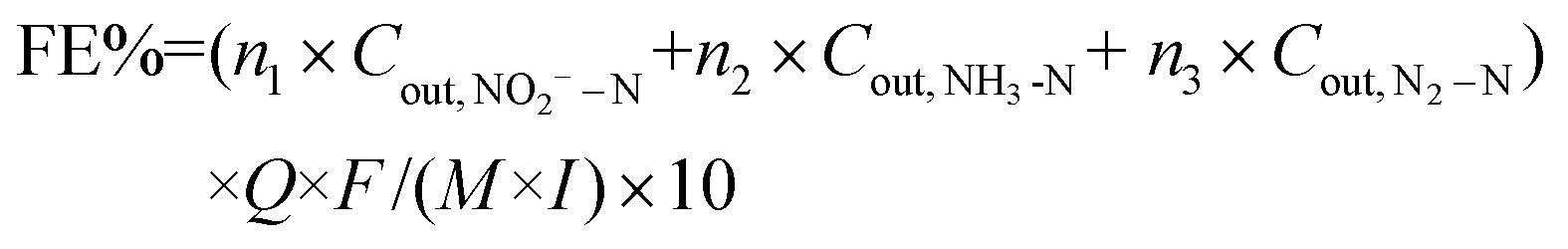
The Pd/MnO2-Ov nanosheets grown on the 3D-porous Ni foam were synthesized via a three-step approach: (i) growth of the uniform MnO2 sheet array on the skeleton of Ni foam (MnO2/Ni foam); (ii) enrichment of Ov on MnO2 nanosheets via an electrochemical reduction method (MnO2-Ov/Ni foam); (iii) further decoration of Pd NPs (Pd–MnO2-Ov/Ni foam). Fig. 1a–d present the representative SEM images of Ni foam, MnO2/Ni foam, MnO2-Ov/Ni foam, and Pd–MnO2-Ov/Ni foam. As observed, MnO2 grows on the smooth skeleton surface of Ni foam and displays a unique intersecting ribbon-like sheet structure. This structure is well preserved during the Ov construction and Pd NP decoration. The Pd NPs are evenly deposited at the sheet surface with little agglomeration. The EDS elemental mapping results in Fig. 1e further demonstrate the even distribution of Pd, Mn, O, and Ni on the skeleton of Ni foam. In Fig. 1f, the HRTEM image of the Pd–MnO2-Ov sheet that is scraped from the Ni foam further evidences the intense and even deposition of Pd NPs with a mean size of 1.4 nm on the MnO2 nanosheet (the NPs display clear lattice fringes with a consistent spacing of 0.238 nm, corresponding to the (111) facet of metallic Pd phase).37 As a comparison, Pd NPs were also deposited over the Ni foam (Pd/Ni foam). The SEM image in Fig. S2a† evidences the larger and aggregated Pd particles (∼20 nm) as well as some Ni(OH)2 nanosheet assemblies. This structure is also verified by the TEM image of the particle that was scraped from the Pd/Ni foam (Fig. S2b†).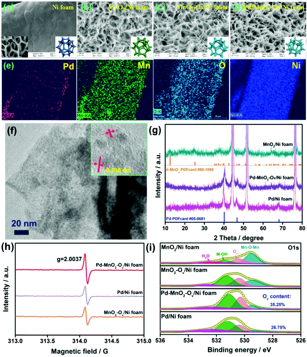 | ||
| Fig. 1 Representative SEM images of (a) Ni foam, (b) MnO2/Ni foam, (c) MnO2-Ov/Ni foam, and (d) Pd–MnO2-Ov/Ni foam; (e) EDS elemental mapping of Pd, Mn, O, and Ni for Pd–MnO2-Ov/Ni foam; (f) TEM image of Pd/MnO2-Ov nanosheet (inset is the corresponding HRTEM image); (g) XRD patterns of electrodes; (h) EPR spectra and (i) high-resolution O 1s XPS spectra for different electrodes. | ||
The XRD patterns of the MnO2/Ni foam, Pd/Ni foam, and Pd–MnO2-Ov/Ni foam in Fig. 1g point to the δ-form of MnO2 (PDFcard #80-1098) and the metallic crystal phase of Pd (PDFcard #05-0681) in all these samples.38,39 No Ni(OH)2 phase is discerned possibly due to its low content. The characteristic diffraction peaks for MnO2 become inconspicuous in the Pd–MnO2-Ov/Ni foam, possibly due to the crystallinity reduction of MnO2 after the Ov introduction or the dense cover of Pd NPs. The ICP analyses reveal that the Pd mass loading on Pd–MnO2-Ov/Ni foam and Pd/Ni foam are similar at 1.6 mg cm−3. The presence of Ov in the MnO2-Ov/Ni foam, Pd/Ni foam, and Pd–MnO2-Ov/Ni foam are evidenced by the strong EPR signal at around g = 2.0037 in their spectra (Fig. 1h) as well as the O 1s XPS peak at 530.4 eV (Fig. 1i).40 The presence of Ov on Pd/Ni foam can be ascribed to the involvement of the Ni(OH)2 species. Fig. 1i also shows that the Pd–MnO2-Ov/Ni foam carries a larger number of Ov than the Pd/Ni foam (35.25% vs. 26.75%), consistent with our speculation that Ov is more readily formed on MnO2.
3.2. NRR performance
The NRR performances of Pd–MnO2-Ov/Ni foam, Pd/Ni foam, and MnO2-Ov/Ni foam electrodes were tested and compared. Given the inherent 3D porous structure of the foam, a continuous-flow reaction cell was customized with the effluent penetrating the electrode, as schemed in Fig. 2a, which allows sufficient mass transfer of NO3−–N around the active sites. Two parallel working electrodes with a distance of 1.0 cm were set to enhance the NRR. Fig. 2b plots the C/C0 of NO3−–N in the effluent as a function of electrolysis time under a working potential of −0.85 V, a flow rate of 0.875 mL min−1, and a feeding NO3−–N concentration of 22.5 mg L−1, by which the NO3−–N conversion efficiency and the rate at the steady state for the electrode can be calculated. As observed, the Pd–MnO2-Ov/Ni foam affords both the largest NO3−–N conversion efficiency of 90.61% and conversion rate of 642 mg N m−2electrode h−1, of which the conversion rate is almost 1.7 and 5.7 times that of the Pd/Ni foam (369 mg N m−2electrode h−1) and Pd-free MnO2-Ov/Ni foam (118 mg N m−2electrode h−1), respectively. As shown by the product distribution in Fig. 2c, NH3–N is the leading product on both the Pd/Ni foam and Pd–MnO2-Ov/Ni foam electrode with a selectivity of 85.02% and 87.64%, respectively, while only a negligible amount of NO2−–N is tracked (3.72 and 0.25% in product). However, on MnO2-Ov/Ni foam, only 34.5% of the NO3− is converted to NH3 (another 30.2% to NO2− and the rest to N2), which confirms the critical role of Pd in the fast and deep reduction of NO3− to NH3. Here, the NH3 is believed to originate from the NO3− conversion rather than the N2 reduction or other impurities in the water as no NH3 is detected once the NO3−–free solution is fed in the flow. Fig. 2d shows that the faradaic current efficiencies for all three electrodes are smaller than 100% due to the side hydrogen evolution reaction (HER). However, the values for the Pd/Ni foam and Pd–MnO2-Ov/Ni foam electrodes are relatively high, approaching 70%.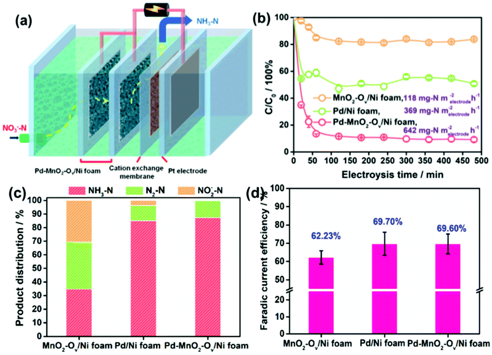 | ||
| Fig. 2 (a) Schematical description of the sealed continuous-flow reaction cell; (b) plots of C/C0 as a function of the reaction time; (c) product distribution in the outlet flow at the steady state (note that the present product distribution is an average of the ones determined during the 480 min of NRR in at least three repeated tests, the same below); (d) faradaic current efficiency for the NRR on MnO2-Ov/Ni foam, Pd/Ni foam, and Pd–MnO2-Ov/Ni foam. | ||
Impacts of the feeding NO3−–N concentration, the flowing rate, the solution pH, and the Pd loading on the NRR performances of the Pd–MnO2-Ov/Ni foam electrode were investigated. Fig. 3a evidences the decrease in the NO3−–N conversion efficiency from 87.06% to 32.87% while the increase in the conversion rate from 642 to 1933 mg N m−2electrode h−1 with the feeding NO3−–N concentration rising from 22.5 to 180.0 mg L−1. Fig. 3b shows that the faradaic current efficiency keeps growing with the increment in NO3−–N concentration and reaches the peak of 89.5% by feeding 180 mg L−1 NO3−–N. It is therefore suggested that the active sites are more specific to the NRR over HER with more NO3−–N supplied. The NH3 selectivity is kept at a high value of around 90% with 22.5–90.0 mg L−1 NO3−–N in the influent (Fig. 3c), while it sharply drops to 55.45% with 180.0 mg L−1 NO3−–N. Correspondingly, the N2 yield rises. According to the previous work, the decreased NH3 yield and the enhanced N2 formation can be attributed to the enlarged N-intermediate/H* (N/H) ratio on catalyst surface when feeding a larger concentration of NO3−–N.41,42
 | ||
| Fig. 3 Impacts of (a–c) the feeding NO3−–N concentration, (d–f) flow rate, (g–i) pH, (j–l) Pd loading, and (m–o) co-existing anions and dissolved organics on the NO3−–N conversion rate, faradaic current efficiency, and product distribution in NRR. | ||
Fig. 3d reveals that an increase in the flow rate from 0.87 to 2.81 mL min−1 reduces the NO3−–N removal efficiency from 87.06% to 52.02%, but raises the NO3−–N conversion rate from 642 to 1171 mg N m−2electrode h−1. This is rationalized by the fact that under the larger flow rate, more NO3− pass by the electrode but stay in a shorter time. Accordingly, a larger proportion of NO3− incline to flow through the electrode before being reduced, leading to the increased NO3− residues in the effluent. Despite these, the absolute amount of the converted NO3−–N is increased as the active sites are feed with more NO3−–N under the larger flow rate. Fig. 3e and f show that with the increase in flow rate, both the faradaic current efficiency and the NH3 selectivity in the product grow, reach the peak at 2.42 mL min−1 and then decrease. Some NO2−–N is even detected at 2.81 mL min−1. Therefore, it is suggested that the uplift of the flow rate but in a suitable range is conducive to acquire pure NH3–N.
Fig. 3g shows that the solution pH has little effect on both the NO3−–N conversion efficiency and rate of the electrode. This is beyond expectation as many previous reports have demonstrated that an acidic condition is beneficial to NRR by affording sufficient protons and alleviating the potential poisoning of active sites (e.g., Ov and the Pd sites) by OH−. This inconsistency might be attributed to the overdose of active sites on the electrode when subjected to the low NO3−–N load, which dilutes the effect of pH. Fig. 3h and i demonstrate that the faradaic current efficiency and the NH3 selectivity are maximized at nearly neutral conditions. As observed in Fig. 3i, the drop in NH3 selectivity primarily originates from the increased N2 yield. The enhanced N2 production in the acidic condition can be ascribed to the formation of HNO3(aq) that readily accumulates and is reduced on the catalyst in comparison to NO3−,43 which contributes to increasing the N/H ratio on electrode, promoting N2 formation. The enhanced N2 production in the alkaline condition can be attributed to the intensified poisoning of Ov by OH− (Fig. S3†). As a result, the NRR primarily occurs on Pd, which, as we know, is one excellent metal to trigger the N2 formation.44
Fig. 3j reveals that an increment in the Pd loading boosts the NO3−–N conversion on the electrode under a NO3−–N feeding concentration of 22.5 mg L−1, which further confirms the critical role of Pd in NO3−–N conversion. Fig. 3k shows that faradaic current efficiency decreases under a larger Pd loading, which results from the enhanced side HER that wastes more electrons. Fig. 3l shows that the moderate Pd loading of 3.2 mgPd cm−3 gives rise to the poorest NH3 selectivity. As Pd occupies the Ov sites during the deposition process, we attribute the higher NH3 selectivity at the lower Pd loading to the larger number of Ov, which survived at the surface, promoting NH3 formation. The higher NH3 selectivity at the higher Pd loading is rationalized by the fact that more H* are exported to the Ov for NO3− reduction, and the resultant smaller N/H ratio is conducive to NH3 formation.
Given the presence of various anions and dissolved organics in natural water, their impacts on the NRR performances of Pd–MnO2-Ov/Ni foam electrodes have to be considered. The carbonate (CO32−, 1.0 mM), sulfite (SO32−, 3.0 mM), and chloridion (Cl−, 5.0 mM) are selected as the probe anions,45 while the humic acid (3.3 mg L−1) is selected to represent the dissolved organics.46 Intriguingly, insignificant differences in the NO3−–N conversion rate, faradaic current efficiency, and NH3 selectivity are observed in Fig. 3m–o after the introduction of anions and humic acid, suggesting the relatively strong resistance of our electrode to the disturbance from natural water environments. The humic acid exhibits some detrimental effects as the NO2− residues increase to 9.87%. It hints that a lower organic content in water is conducive to the efficient and complete conversion of NO3− to NH3.
3.3. The dual-site catalysis mechanism
As observed, the Pd–MnO2-Ov/Ni foam delivers both the high NO3− conversion rate and NH3 selectivity, which can be expected by the proposed dual-site reaction mechanism that the Ov site adsorbs and activates NO3− while the Pd site generates H* and exports them to the Ov site for NRR. To confirm this mechanism, DFT calculations on the adsorption energy of H*, N*, and O*, as well as the Gibbs free energy changes for the NO3− conversion to NH3 and N2 on MnO2, MnO2-Ov, and Pd surfaces, were performed. The δ-MnO2 (001) surfaces without and with one Ov are chosen to model fine MnO2 and MnO2-Ov, while Pd (111) is selected as the active Pd surface. Fig. S3† reveals that the H* adsorption on MnO2-Ov is much weaker than that on Pd, confirming the better performance of Pd in proton harvest (the over-strong H adsorption on fine MnO2 can be ascribed to the formation of –OH groups. This H species is inert and cannot be used in NRR). Combining these calculation results with the poor NRR performance of the single MnO2-Ov in Fig. 2b, we are ascertained that the H* required for NRR is primarily provided by Pd.Fig. 4a and b compare the Gibbs free energy changes (ΔG) of the elementary reactions occurring during the NO3− conversion to N2 and NH3 on Pd (111) and MnO2-Ov (001), respectively. The N-intermediates and elementary reactions are set according to the literature.14,47,48 Basically, the NRR can be divided into two stages: (I) NO3− adsorption and its conversion to NO2*, which is well-known as the rate-determining step of NRR; (II) NO2* conversion to N2 or NH3, which is considered as the determinant of product selectivity. As observed, the process I on the MnO2-Ov surface is spontaneous with an overall negative ΔG of −3.56 eV, while that on the Pd surface has to overcome an energy barrier of 0.51 eV (0.48 eV for NO3− adsorption and 0.03 eV for NO3* hydrogenation). More intriguingly, Ov is found to have the ability to grab one O atom from both NO3* and NO2* and complete the NO3*–NO* conversion along with their adsorption processes. All these calculation results clearly verify that NO3− is preferred to be adsorbed and activated on MnO2-Ov rather than the Pd site. It should be mentioned that Ov is filled by the oxygen atoms during the NO3−/NO2* activation and should be regenerated under the synergy of polarization potential and H* by overcoming an energy barrier of 0.87 eV ((1.23–0.36) eV).
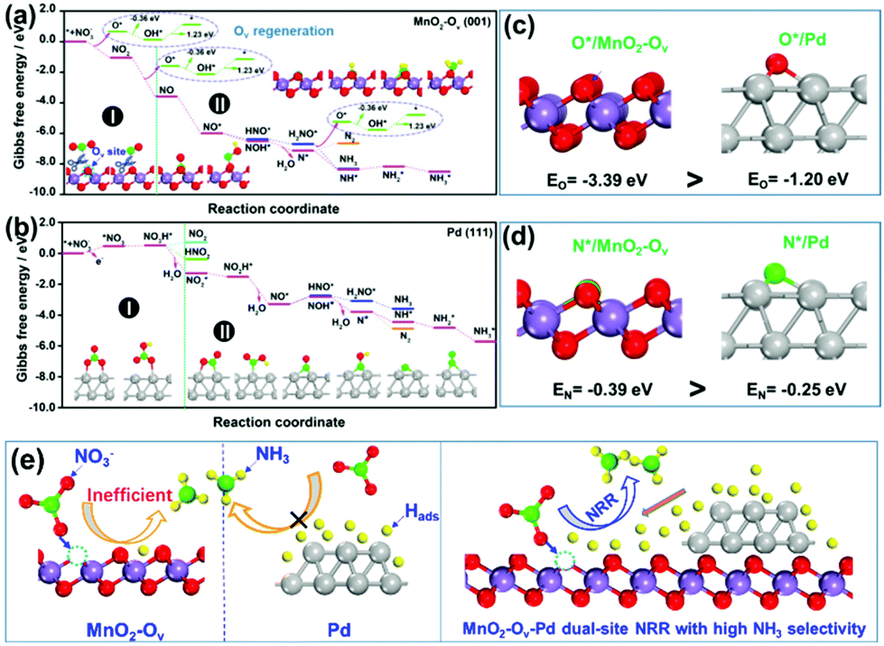 | ||
| Fig. 4 The reaction energy diagram for the conversion of NO3− to N2 and NH3 over (a) clean MnO2-Ov (001) and (b) Pd (111) facet; adsorption energies of (c) one oxygen atom and (d) one nitrogen atom on MnO2-Ov (001) and Pd (111) facets; (e) schematical illustration of the MnO2-Ov-Pd dual-site NRR mechanism for a high NH3 selectivity. | ||
In stage II, the NO* on MnO2-Ov is ready to be deeply hydrogenated to NH3* in an energetically favored pathway of NO* → NOH* → N* → NH* → NH2* → NH3* with the ΔG of all the steps displaying negative values. The N2 formation is relatively difficult as the N*–N* pairing requires extra energy of 0.43 eV. In comparison, the NO2* conversion to NH3 and N2 on Pd (111) experiences similar energy profiles, pointing to the relatively poor product selectivity to NH3 or N2 on the Pd site. This is consistent with the previous reports that a mixed product of NH3 and N2 can be formed on Pd-based catalysts.49,50 Combining the calculation results with the high NH3 selectivity of Pd–MnO2-Ov in Fig. 2c, we are ascertained that the Ov site is the active center for the selective conversion of NO3− to NH3.
We also examined the adsorption energies of N* and O* on MnO-Ov and Pd, and the results in Fig. 4c and d reveal the much stronger adsorption of O* and N* on the Ov site of MnO2-Ov than that on Pd. Given the linear scale of the adsorption energies for N-intermediates with that for either an oxygen or nitrogen atom,51,52 all the N-intermediates are believed to be preferably immobilized and reduced at the Ov site during NRR, which reduces their encountering possibilities and contributes to high NH3 selectivity.
On the basis of all the above, we firmly believe the dual-site NRR mechanism on MnO2-Ov–Pd, which is schematically described in Fig. 4e. The Ov serves to adsorb, immobilize, and activate the NO3− and N-intermediates, while Pd supplies the Ov with sufficient H* for both the NRR and Ov refreshment. Such a dual-site NRR mechanism accounts for both the efficient NRR and the high NH3 selectivity.
4. Conclusions
This work demonstrates the superior performance of the three-dimensional porous Pd–MnO2-Ov/Ni foam electrode for NRR. In a continuous-flow reaction cell, it delivers a substantial NO3−–N conversion rate of 642 mg N m−2electrode h−1 and a NH3 selectivity of 87.64% under −0.85 V when feeding a 22.5 mg L−1 NO3−–N solution at a rate of 0.875 mL min−1, outperforming the Pd/Ni foam (369 mg N m−2electrode h−1, 84.02%) and MnO2-Ov/Ni foam (118 mg N m−2electrode h−1, 32.25%). Combining the experimental characterizations and the theoretical calculations, we confirm the dual-site NRR process on Pd–MnO2-Ov, in which the MnO2-Ov serves to adsorb, immobilize, and activate the NO3− and the N-intermediates, while Pd supplies the Ov with sufficient H* for both the NRR and Ov refreshment. This work highlights the critical role of dual-site catalysis in the efficient and selective nitrate conversion to NH3, paving the way for utilizing dual-site catalysis in both the nitrate pollution abatement and nitrogen resource recycling from nitrate wastewater.Conflicts of interest
The authors declare no competing financial interest.Acknowledgements
We acknowledge the funding support from the National Natural Science Foundation of China (2217061059 and 51978110), the Program for the Top Young Talents of Chongqing, Innovation group of new technologies for industrial pollution control of Chongqing Education Commission (CXQT19023), and Science and Technology Research Program of Chongqing Municipal Education Commission (KJQN201800829 and KJZD-K202000802).Notes and references
- L. Liu, X. Zhang, W. Xu, X. Liu, Y. Li, J. Wei, M. Gao, J. Bi, X. Lu, Z. Wang and X. Wu, J. Agric. Food Chem., 2020, 68, 3354–3361 CrossRef CAS PubMed.
- F. Jiao and B. Xu, Adv. Mater., 2019, 31, 1805173 CrossRef PubMed.
- N. Lazouski, M. Chung, K. Williams, M. L. Gala and K. Manthiram, Nat. Catal., 2020, 3, 463–469 CrossRef CAS.
- Y. Zhao, L. Zheng, R. Shi, S. Zhang, X. Bian, F. Wu, X. Cao, G. I. N. Waterhouse and T. Zhang, Adv. Energy Mater., 2020, 10, 2002199 CrossRef CAS.
- M. C. Kim, H. Nam, J. Choi, H. S. Kim, H. W. Lee, D. Kim, J. Kong, S. S. Han, S. Y. Lee and H. S. Park, ACS Catal., 2010, 10, 10577–10584 CrossRef.
- G. M. Jiang, X. W. Li, M. N. Lan, T. Shen, X. S. Lv, F. Dong and S. Zhang, Appl. Catal., B, 2017, 205, 532–540 CrossRef CAS.
- Y. Zeng, C. Priest, G. Wang and G. Wu, Small Methods, 2020, 4, 2000672 CrossRef CAS.
- Y. T. Wang, Y. F. Yu, R. R. Jia, C. Zhang and B. Zhang, Natl. Sci. Rev., 2019, 6, 730–738 CrossRef CAS.
- X. Fu, X. Zhao, X. Hu, K. He, Y. Yu, T. Li, Q. Tu, X. Qian, Q. Yue, M. R. Wasielewski and Y. Kang, Appl. Mater. Today, 2020, 19, 100620 CrossRef.
- C. Yu, X. Huang, H. Chen, H. C. J. Godfray, J. S. Wright, J. W. Hall, P. Gong, S. Ni, S. Qiao, G. Huang, Y. Xiao, J. Zhang, Z. Feng, X. Ju, P. Ciais and N. C. Stenseth, Nature, 2019, 567, 516–520 CrossRef CAS PubMed.
- S. Wang, X. Zhang, C. Wang, X. Zhang, S. Reis, J. Xu and B. Gu, Sci. Data, 2020, 7, 379 CrossRef PubMed.
- J. Wang, T. Feng, J. Chen, V. Ramalingam, Z. Li, D. M. Kabtamu, J. H. He and X. Fang, Nano Energy, 2021, 86, 106088 CrossRef CAS.
- T. Zhu, Q. Chen, P. Liao, W. Duan, S. Liang, Z. Yan and C. Feng, Small, 2020, 16, 2004526 CrossRef CAS PubMed.
- X. D. Wang, M. Q. Zhu, G. S. Zeng, X. Liu, C. Fang and C. H. Li, Nanoscale, 2020, 12, 9385–9391 RSC.
- X. Chen, T. Zhang, M. Kan, D. Song, J. Jia, Y. Zhao and X. Qian, Environ. Sci. Technol., 2020, 54, 13344–13353 CrossRef CAS PubMed.
- Y. T. Wang, W. Zhou, R. R. Jia, Y. F. Yu and B. Zhang, Angew. Chem., Int. Ed., 2020, 59, 5350–5354 CrossRef CAS PubMed.
- R. R. Jia, Y. T. Wang, C. H. Wang, Y. F. Ling, Y. F. Yu and B. Zhang, ACS Catal., 2020, 10, 3533–3540 CrossRef CAS.
- H. Hirakawa, M. Hashimoto, Y. Shiraishi and T. Hirai, J. Am. Chem. Soc., 2017, 139, 10929–10936 CrossRef CAS PubMed.
- D. A. Tompsett, S. C. Parker and M. S. Islam, J. Am. Chem. Soc., 2014, 136, 1418–1426 CrossRef CAS PubMed.
- J. Liu, Y. Wei, P.-Z. Li, P. Zhang, W. Su, Y. Sun, R. Zou and Y. Zhao, ACS Catal., 2018, 8, 3865–3874 CrossRef CAS.
- G. Zhu, J. Zhu, W. Li, W. Yao, R. Zong, Y. Zhu and Q. Zhang, Environ. Sci. Technol., 2018, 52, 8684–8692 CrossRef CAS PubMed.
- M. Zang, N. Xu, G. Cao, Z. Chen, J. Cui, L. Gan, H. Dai, X. Yang and P. Wang, ACS Catal., 2018, 8, 5062–5069 CrossRef CAS.
- T. Zheng, W. Sang, Z. He, Q. Wei, B. Chen, H. Li, C. Cao, R. Huang, X. Yan, B. Pan, S. Zhou and J. Zeng, Nano Lett., 2017, 17, 7968–7973 CrossRef CAS PubMed.
- Y. Y. Peng, M. Y. Cui, Z. Y. Zhang, S. Shu, X. L. Shi, J. T. Brosnahan, C. Liu, Y. L. Zhang, P. Godbold, X. M. Zhang, F. Dong, G. M. Jiang and S. Zhang, ACS Catal., 2019, 9, 10803–10811 CrossRef CAS.
- W. Yu, H. Jiang, J. Fang and S. Song, Environ. Sci. Technol., 2021, 55, 10087–10096 CrossRef CAS PubMed.
- X. Li, X. Huang, S. Xi, S. Miao, J. Ding, W. Cai, S. Liu, X. Yang, H. Yang, J. Gao, J. Wang, Y. Huang, T. Zhang and B. Liu, J. Am. Chem. Soc., 2018, 140, 12469–12475 CrossRef CAS PubMed.
- S. Campisi, C. E. Chan-Thaw, L. E. Chinchilla, A. Chutia, G. A. Botton, K. M. H. Mohammed, N. Dimitratos, P. P. Wells and A. Villa, ACS Catal., 2020, 10, 5483–5492 CrossRef CAS.
- N. Liu, M. Xu, Y. Yang, S. Zhang, J. Zhang, W. Wang, L. Zheng, S. Hong and M. Wei, ACS Catal., 2019, 9, 2707–2717 CrossRef CAS.
- W. Duan, G. Li, Z. Lei, T. Zhu, Y. Xue, C. Wei and C. Feng, Water Res., 2019, 161, 126–135 CrossRef CAS PubMed.
- G. Kresse and J. Furthmüller, Phys. Rev. B: Condens. Matter Mater. Phys., 1996, 54, 11169–11186 CrossRef CAS PubMed.
- J. P. Perdew, K. Burke and M. Ernzerhof, Phys. Rev. Lett., 1996, 77, 3865–3868 CrossRef CAS PubMed.
- D. R. Hamann, M. Schlüter and C. Chiang, Phys. Rev. Lett., 1979, 43, 1494–1497 CrossRef CAS.
- X. Guo, J. Gu, S. Lin, S. Zhang, Z. Chen and S. Huang, J. Am. Chem. Soc., 2020, 142, 5709–5721 CrossRef CAS PubMed.
- J. H. Montoya, C. Tsai, A. Vojvodic and J. K. Norskov, ChemSusChem, 2015, 8, 2180–2186 CrossRef CAS PubMed.
- S. Grimme, J. Comput. Chem., 2006, 27, 1787–1799 CrossRef CAS PubMed.
- M. Bajdich, M. Garcia-Mota, A. Vojvodic, J. K. Nørskov and A. T. Bell, J. Am. Chem. Soc., 2013, 135, 13521–13530 CrossRef CAS PubMed.
- G. M. Jiang, X. J. Li, Y. Shen, X. L. Shi, X. S. Lv, X. M. Zhang, F. Dong, G. X. Qi and R. Liu, J. Catal., 2020, 391, 414–423 CrossRef CAS.
- X. Fang, Y. Liu, W. Cen and Y. Cheng, Ind. Eng. Chem. Res., 2020, 59, 14606–14615 CrossRef CAS.
- W. Yang, Y. Zhu, F. You, L. Yan, Y. Ma, C. Lu, P. Gao, Q. Hao and W. Li, Appl. Catal., B, 2018, 233, 184–193 CrossRef CAS.
- J. Wang, J. G. Wang, X. Qin, Y. Wang, Z. You, H. Liu and M. Shao, ACS Appl. Mater. Interfaces, 2020, 12, 34949–34958 CrossRef CAS PubMed.
- S. Hamid, M. A. Kumar and W. Lee, Appl. Catal., B, 2016, 187, 37–46 CrossRef CAS.
- P. J. Kuang, K. Natsui and Y. Einaga, Chemospere, 2018, 210, 524–530 CrossRef CAS PubMed.
- C. A. Clark, C. P. Reddy, H. Xu, K. N. Heck, G. H. Luo, T. P. Senftle and M. S. Wong, ACS Catal., 2019, 494–509 Search PubMed.
- H. Shin, S. Jung, S. Bae, W. Lee and H. Kim, Environ. Sci. Technol., 2014, 48, 12768–12774 CrossRef CAS PubMed.
- Y. M. Kang, M. K. Kim and K. D. Zoh, Chemosphere, 2018, 204, 148–155 CrossRef CAS PubMed.
- B. P. Chaplin, E. Roundy, K. A. Guy, J. R. Shapley and C. J. Werth, Environ. Sci. Technol., 2006, 40, 3075–3081 CrossRef CAS PubMed.
- R. Jia, Y. Wang, C. Wang, Y. Ling, Y. Yu and B. Zhang, ACS Catal., 2020, 10, 3533–3540 CrossRef CAS.
- J. Long, S. M. Chen, Y. L. Zhang, C. X. Guo, X. Y. Fu, D. H. Deng and J. P. Xiao, Angew. Chem., Int. Ed., 2020, 59, 9711–9718 CrossRef CAS PubMed.
- H. Li, S. J. Guo, K. Shin, M. S. Wong and G. Henkelman, ACS Catal., 2019, 9, 7957–7966 CrossRef CAS.
- P. Gayen, J. Spataro, S. Avasarala, A. M. Ali, J. M. Cerrato and B. P. Chaplin, Environ. Sci. Technol., 2018, 52, 9370–9379 CrossRef CAS PubMed.
- J. X. Liu, D. Richards, N. Singh and B. R. Goldsmith, ACS Catal., 2019, 9, 7052–7064 CrossRef CAS.
- J. P. Troutman, H. Li, A. M. Haddix, B. A. Kienzle, G. Henkelman, S. M. Humphrey and C. J. Werth, ACS Catal., 2020, 10, 7979–7989 CrossRef CAS.
Footnotes |
| † Electronic supplementary information (ESI) available. See DOI: 10.1039/d1nr04962c |
| ‡ These two authors contribute equally to this work. |
| This journal is © The Royal Society of Chemistry 2021 |