
 Open Access Article
 This Open Access Article is licensed under a
 Creative Commons Attribution 3.0 Unported Licence
Effect of coverage on the magnetic properties of –COOH, –SH, and –NH2 ligand-protected cobalt nanoparticles†
Barbara
Farkaš
 a and
Nora H.
de Leeuw
*ab
a and
Nora H.
de Leeuw
*ab
aSchool of Chemistry, Cardiff University, Cardiff CF10 3AT, UK
bSchool of Chemistry, University of Leeds, Leeds LS2 9JT, UK. E-mail: N.H.deLeeuw@leeds.ac.uk
First published on 24th June 2021
Abstract
Implementation of magnetic nanoparticles in biomedicine requires their passivation, which often comes at a cost of diminished magnetic properties. For the design of nano-agents with targeted magnetic behaviour, it is important to distinguish between ligands which can improve desired performance, and those that reduce it. Carboxylic acid-, thiol-, and amine-protected cobalt nanoparticles were studied by density functional theory calculations to model the impact of ligand coverage on the magnetic properties. The simulations show that the functional group, arrangement, and coverage density of the ligand coating control both the total magnetic moment and magnetic anisotropy energy of the nanoparticle, as well as the distribution of local spin magnetic moments across the metallic core. Captured effects of ligand binding on the orbital moments of cobalt atoms were insignificant. Out of the three ligand families, only carboxylic acid coatings increased the magnetic moments of cobalt nanoparticles, while amines and thiols quenched them. Calculated anisotropy energies of protected nanoparticles consistently increased with the growing ligand density, reaching the highest values for a 100% coverage of both carboxylic acid and thiol coatings. However, the binding nature of the two functional groups showed opposite impacts on the d-states of interacting cobalt atoms. This study has thus established important principles for the design of biocompatible magnetic nanocomposites, highlighting different routes to achieve desired magnetic behaviour.
Introduction
Nanomagnetic materials have been shown to be a powerful platform offering tuneable properties defined by a wide range of parameters, including dimensions, morphology, composition, and surface chemistry.1–7 Over recent years, their implementation has expanded from energy and data storage, to magnetically induced catalysis and drug delivery.8–12 Besides serving as a reliable miniature drug carrier, magnetism at the nanoscale recently found another promising function – a source of controllable heat generation, which has already been successfully tested for hyperthermia treatments.13–17 Since this specific application requires sufficiently high values of magnetisation throughout the duration of the therapy, naturally magnetic Ni, Co, and Fe nanoparticles (NPs) have generated a lot of interest in thus far unsuccessful efforts to improve magnetic moments in their corresponding biocompatible oxides.18–20 When comparing the heating power of various metallic NPs, cobalt was detected to have the best potential within NPs under 10 nm in diameter.21–23 However, there are formidable challenges in adapting these metallic nano-systems to functional biomaterials, including their stability, aggregation, and disintegration under physiological conditions. Effective protection has so far been accomplished through ligand-mediated stabilisation by a variety of organic molecules which can form strong ionic or covalent bonds with the surface metal atoms.In general, nano-sized metallic particles are known to exhibit enhanced electronic and magnetic properties compared to their respective bulk phases. Average magnetic moments of Co atoms in nanoclusters were measured by gas phase experiments to be as high as 2.6μB, which is more than 50% higher than the magnetic moment of bulk hcp Co (1.72μB) as a result of the under-coordinated surface atoms.24 This phenomenon was confirmed in computational reports on small clusters and medium-sized Co NPs.25–27 Furthermore, dependence on the morphology was also established through thorough experimental and theoretical studies, whereas organic coatings can also have a significant impact on the final electronic structure of metal NPs. The extent of ligand-induced changes depends on the type of both metal and ligand. Experiments indicate that gold NPs functionalised with organic molecules show complex magnetic behaviours, despite their starting structures having zero magnetic moment. Overall magnetisation ranges from 0.0036–1.00μB measured on thiolate-capped gold NPs to over 10 Bohr magnetons per adsorbed molecule of polypeptides on gold substrates.28–30 In contrast, two types of cobalt NPs of substantially dissimilar structural and magnetic features were synthesised in the presence of precursors containing different kinds of ligands.31 The divergence in properties was directly linked to the difference in the chemical environments, where phosphide-based ligands brought a 38% loss of magnetisation, while NPs synthesised via an amino route displayed unaltered magnetic properties.
Understanding contributions from the nature and structure of the ligands to the electronic, and consequently physical and chemical properties of these nano-systems is thus crucial for the effective utilisation of ligand-mediated magnetisation. Density functional theory (DFT) calculations have proved to be a reliable tool in describing magnetism of metallic and semiconducting materials, as well as explaining the mechanisms behind the occurrence of such magnetic behaviour.32–37 Using DFT calculations, the origin of unexpected magnetisation as observed within capped Au NPs has been traced to the charge transfer between organic molecules and the metallic core that can lead to the rearrangement in the occupied energy states, which are associated with the magnetic properties of these complex systems.38,39 Unusual magnetic behaviour was connected only to thiol ligands, while nitrogen-based molecules did not bring similar changes. Effects of organic ligands on magnetic moments of cobalt NPs have not been investigated as much. Recent computational studies have shown diverse magnetic quenching of simple cobalt–ligand systems, indicating that the magnetisation can be tuned by a careful design of the coating.40,41 Eleven unique ligand shell compositions were considered, mainly combinations of phosphine groups and halogen atoms, displaying different strengths in the decrease of the magnetisation. Changes were linked to the exchange of electrons, with electronegativity as a main factor in the final magnetisation of the composite system. Finally, it was found that, with increase in the size of the cluster, the dependence of magnetic properties on the presence of ligand molecules, although dampened, still persists.
However, a broad understanding of the fundamental principles that describe the changes in the magnetism of Co NPs functionalised by biomedically acceptable ligands does not currently exist. Thiols have been widely utilised for the protection of gold NPs implemented in chemical and biological sensing,42,43 whereas carboxylic acids are known to strongly bind to metallic NPs through the formation of covalent bonds and such systems have been synthesised with respectable stabilities.44–46 Their effect on the magnetisation remains largely unknown. In addition, studies on magnetic nanoparticle hyperthermia have shown that the heating efficiency is proportional not only to the NP magnetisation, but it also depends on the value of the magnetic anisotropy energy (MAE).47,48 It has been recently demonstrated that the deposition of a self-assembled monolayer of alkanethiolates on an ultrathin Co film grown on Au(111) induces a spin reorientation transition from in-plane to out-of-plane magnetisation, changing the anisotropy values.49 This work hence focuses on the evolution of the electronic and magnetic properties of carboxylic acid-, thiol-, and amine-protected cobalt NPs as a function of the ligand coverage. Evaluation of this dependence was conducted through the analysis of atomic Bader charges, spin and orbital magnetic moments, densities of state, and magnetic anisotropy energies, and correlation of these values to general trends in the considered systems.
Models and methods
The structural and magnetic properties of ligand-protected cobalt NPs were determined within the spin-polarised DFT framework of the Vienna Ab initio Simulation Package (VASP),50 employing the generalised gradient approximation (GGA) of the Perdew, Burke, and Ernzerhof (PBE) exchange functional.51 This level of theory has previously provided satisfactory description of a series of properties in nanosized cobalt systems in good agreement with available experimental data.26,27,52–54 The spatially confined core electrons were treated through the projector augmented wave (PAW) approach,55 while the intrinsically non-periodic nature of the system restricted the Brillouin zone sampling to the Γ-point. The wave functions of the valence electrons were expanded to an energy cut-off of 400 eV, which was sufficiently large to satisfy requirements of the accuracy in small energy differences needed to determine the MAE. The DFT-D3 method with Becke–Johnson damping was used to include the long-range dispersion interactions with the ligands.56Relaxations were carried out with a convergence criterion of 10–6 eV between consecutive steps without any structural, symmetry, or magnetic constraints, and optimised structures were used both in the analysis of NP properties and as the starting point for ligand-protected geometries. Ligand molecules were placed randomly on the surface of the NP, and their number increased progressively until full coverage had been reached. Full coverage was deemed to be achieved once every surface Co atom has formed a single bond with one ligand molecule. Charge distribution was calculated using the Bader charge analysis, as implemented by Henkelman et al.57 Magnetic moments were determined iteratively through simultaneous optimisation during the self-consistent field (SCF) procedure.
To predict spin–orbit-related properties, namely orbital magnetic moments and magnetic anisotropy energies, fully relativistic calculations including spin–orbit coupling (SOC) were performed.58,59 This required the non-collinear version of the VASP code developed by Hobbs et al. and Marsman and Hafner.60,61 These properties require extremely well-converged wave functions and charge densities, which hence necessitated tightening the criteria for termination of the SCF cycles to 10–7 eV per cell and enforcing energy changes to less than a hundredth of a meV. Two sets of self-consistent SOC non-collinear calculations were performed, one for each easy and hard magnetisation axis, and the MAE was determined in terms of the difference in their total energies. In principle, such approach, although time-consuming, is exact and straightforward.
Additional details can be found in the ESI.†
Results and discussion
First, the magnetic structure of bulk cobalt and unprotected Co NPs was examined to validate calculated properties against available experimental and theoretical results. The accuracy of the setup regarding structural and electronic properties for Co NPs of diverging shapes and sizes has already been proven in previous work to be satisfactory.25 Calculated magnetic moments of bulk hcp and fcc cobalt are 1.596μB and 1.664μB with orbital magnetic moments of 0.071μB and 0.074μB. Total magnetic moments of 1.67 (hcp) and 1.74μB (fcc) per atom correspond well to the experimentally determined magnetisation of 1.72 and 1.75μB for the hexagonal and cubic phase, respectively.62Predicted magnetic anisotropy energies of bulk hcp and fcc cobalt have values of 27.195 and −1.536 μeV per Co atom, Table 1. The energies were obtained with dense k-point meshes, 21 × 21 × 15 for hcp and 20 × 20 × 20 for fcc Co. The calculated value for the hcp phase is considerably lower compared to the experimental data, which is a well-known deficiency of the DFT approach and in accord with other theoretical works.59,63 A systematic study of the comparison of the Co MAE as obtained by various exchange–correlation functions and initial magnetic moment parameters showed no prominent difference between GGA functionals (PBE, PBE-pv, PBE-sv, and PW91), with all four correctly predicting the easy axis of magnetisation.63 Additionally, the results of the study indicate that the magnitude of the MAE underestimation is similar regardless of the chosen functional. Despite this underestimation of the MAE for bulk hcp Co, the qualitative trend for the variation of the MAE values as a function of ligand coverage density is expected to be captured properly.
![[thin space (1/6-em)]](https://www.rsc.org/images/entities/char_2009.gif)
The computational expense of non-collinear DFT calculations limited the determination of MAE to particles with 0.75–2.00 nm diameters (50–200 atoms). The NP morphologies considered and their accompanying axes of magnetisation are depicted in Fig. 1 and described in more detail in the ESI,† while the obtained MAE values per Co atom are summarised in Table 2.
 | ||
| Fig. 1 Schematic representation of different magnetisation axes considered in calculations of magnetic anisotropy of Co NPs with various morphologies (top: hcp, icosahedron, truncated octahedron; bottom: regular, Marks, and Ino decahedron). | ||
| MAE/μeV per atom | hcp | Icosahedron | Truncated octahedron | Cuboctahedron | Regular decahedron | Ino decahedron | Marks decahedron |
|---|---|---|---|---|---|---|---|
[10![[1 with combining macron]](https://www.rsc.org/images/entities/char_0031_0304.gif) 0]-[0001] 0]-[0001] |
[100]-[001] | [110]-[001] | [110]-[001] | [100]-[001] | [100]-[001] | [100]-[001] | |
| 0.75–1.00 nm | −49.0 | 1.5 | 11.9 | 12.4 | −1.2 | ||
| 1.50–2.00 nm | −19.4 | 4.1 | 8.1 | 13.1 | −30.0 | −77.8 | −29.4 |
For hcp shaped Co NPs, the two chosen orientations of the magnetisation were the one along the z-axis perpendicular to the (0001) facets and the other one along the x-axis in the direction of an edge joining two (101) facets (coinciding with the (100) directional growth). The latter was determined to be an easy magnetisation axis, with MAE values of −49.0 and −19.4 μeV per atom for Co NPs containing 57 and 153 atoms, respectively. For morphologies originating from a cubic bulk phase, namely cuboctahedron and truncated octahedron, considered magnetisation orientations were consistent with the growth directions of exposed facets or their conjoining edges, as was the case with hcp NPs. The axis coinciding with the directional growth of the (001) surface was detected to be an easy magnetisation axis for both morphologies, and MAE was calculated to be 11.9 μeV per Co atom for a 38-atom truncated octahedron and 12.4 μeV per Co atom for a 55-atom cuboctahedron, which are considerably reduced values compared to their 57-atom hcp counterpart. The 201-atom truncated octahedron and 147-atom cuboctahedron particles showed anisotropy values of 8.1 and 13.1 μeV per atom, respectively. The icosahedron, as a non-crystalline shape with solely (111) fcc facets, was found to have the lowest value of anisotropy which was calculated at 1.5 μeV per Co atom for the 55-atom particle. Even for a larger icosahedral particle with 147 atoms, the calculated MAE per atom was only 4.1 μeV. Finally, anisotropy energies of the least curvaceous NP shapes, regular and irregular decahedra, were amongst the highest calculated: −29.4 μeV per atom for the 100-atom Marks decahedron, −30.0 μeV per atom for the 105-atom regular decahedron, and −77.8 μeV per atom for the Ino decahedron with 147 atoms.
The reversed MAE directions of crystalline NPs compared to hcp and fcc Co bulk are a consequence of the various types of anisotropy present within the NPs, including surface anisotropy, shape anisotropy, and magneto-crystalline anisotropy, which arise from the abrupt ending of the crystallite and reduced number of closest neighbours, symmetry breaking, surface relaxation, and varying facet population and orientation.68,69 The NP shape and surface anisotropies can become comparable to, or even higher than, the bulk magneto-crystalline anisotropy.70–72 Additionally, magnetic axes for the shape and surface anisotropy may not be the same, because the former is related to the particle morphology and the latter to its faceting.73 Changes in the magnetisation axis were already detected for Co NPs with distinct polycrystallinity and facet alternations.74 A cumulative contribution of each anisotropy type ultimately determines the preferential orientation of NP magnetisation, in contrast to the uniaxial anisotropy of the bulk.
Experimentally measured magnetic anisotropy energies of Co NPs are reported to be in the range of 600–3000 kJ m−3, consistently above the bulk values (−23.6 kJ m−3 fcc and 700–800 kJ m−3 hcp at 0 K).24,65,70,75,76 The volume-expressed MAE obtained in this study ranges from 30.2 kJ m−3 to 1412.5 kJ m−3. Geometrical shapes of the particles are not always provided in experimental studies, but it is suspected that they are mostly fcc crystalline or icosahedral Co NPs. Moreover, several studies of varying NP sizes and morphologies have observed the coexistence of crystallographic structures in both gas and deposited phase,77–80 especially without further annealing. Calculated MAE of fcc motifs as a function of NP diameter in this work, MAE (∼0.7, 1.0, 1.4, 1.5 nm) = 439.9, 254.5, 211.7, 194.5 kJ m−3, correspond well to the experimentally measured fcc NP trend, MAE (1.9, 2.7, 3.2, 3.5, 3.8, 4.7, 5.5 nm) ≈ 218, 135, 114, 110, 154, 182, 180 kJ m−3, Fig. S1.†81 Experimental data have been complemented by the Néel pair modelling to correlate the observed MAE features to the increased importance of the exposed fcc facets, namely those of the (100) and (111) surfaces. Addition of a single facet does not significantly contribute to the NP geometry, but it is sufficient to break the symmetry and induce a change in the MAE. Such increase of the surface area successfully reproduced experimentally observed effects of the increased MAE values with respect to the bulk for the smallest sizes and varying MAE trend with decreasing size. Herein calculated MAE for 0.7–2.0 nm icosahedra (30.2 and 65.6 kJ m−3) agree with the derived values of 10–400 kJ m−3 for icosahedral Co NPs in the 3.1–4.3 nm size range.82 For a specific case of 3.0 nm truncated octahedral particles, experimental anisotropy constants are in the range of 10–200 kJ m−3, also in a good agreement with the herein obtained value of 194.5 kJ m−3 for a 2.0 nm diameter.70
In general, the spin moments, Si, of Co atoms within the considered NP morphologies do not depend significantly on the direction of magnetisation. In contrast, orbital moments, Li, were captured to be very sensitive to the chosen magnetisation axis, Fig. S2,† showing relation between the anisotropy in orbital moments and anisotropy in electronic energy, Lz − Lx ∝ Ez − Ex.83 This inverse behaviour of spin and orbital moments is characteristic for magnetic nanostructures defined by a large exchange regime, as found in various transition metal clusters and NPs with alternating symmetries, as well as in the magnetic thin films of distinct packings.84,85
With geometries, electronic structure, and magnetic properties of the bare NPs in hand, next the impact of ligands on the magnetic behaviour can be investigated. The choice was narrowed to two morphologies of interest: icosahedron, which is well-known as the most stable shape for small and medium Co NPs,86–89 and hcp, as the expected geometry for large NPs because of the natural hcp stacking of the bulk material.25 Moreover, several publications relate the use of hcp Co NPs for magnetisation-based applications due to the requirement of small NPs with high anisotropy at usable temperatures, and hcp Co NPs of varying diameters have already been successfully synthesised.90–94 As it has been shown that size-dependent effects are not prevalent in changes of the magnetic properties of Co clusters induced by ligand coatings,41 only the influence of the density of the coating on the magnetisation of the 55-atom icosahedron and 57-atom hcp NPs was considered. Ten different coverages of three ligand functional groups commonly used for biocompatibility (–SH, –COOH, and –NH2) were modelled on the icosahedral NP, increasing from 10% to a full 100% coverage in steps of 10%. Acetic acid, ethanamine, and ethanethiol were chosen as ligand molecules. Motivated by previous results from ab initio molecular dynamics simulations which captured spontaneous dissociation of the 5C counterpart ligands and the accompanying generation of gaseous hydrogen, ligand molecules were herein introduced to the surface in their dissociated forms.102 In accord with the most favourable binding modes suggested by experimental studies and DFT/metadynamics calculations, initial forms of interaction of acetic acid, ethanamine, and ethanethiol molecules were bridging bidentate, bridging monodentate, and three-fold monodentate, respectively.44,95–98 No changes in the interaction modes were observed upon the structural optimisation. Density of the passivating coating was determined as the number of Co atoms interacting with adsorbed molecules over the total number of surface Co atoms, where full coverage is reached once every surface Co atom interacts with one ligand molecule through a single bond. On the hcp NP, the role of progressive passivation of two different facets exposed on the surface of the NP, (0001) and (101), by carboxylic acid ligands was examined. Optimised structures of representative systems are shown in Fig. 2. Together, these systems sample a range of possible biocompatible shells used to form ligand-protected Co NPs, with carboxyl and thiol molecules commonly seen as coatings of respectable stabilities in literature.
 | ||
| Fig. 2 Optimised geometries of representative ligand systems considered: a. 100% coverage of carboxylic acid, amine, and thiol coating on a 55-atom icosahedral Co NP; b. 50% coverage of carboxylic acid coating on a 57-atom hcp Co NP with primary distribution on the (0001) surface, mixed over both surface types, and concentrated on the (101) surface. Each case is shown as a full molecule representation (top panel) and by only including ligand functional groups (bottom panel). | ||
The strength of interaction of the adsorbed molecules was captured through the binding energy per ligand molecule, Eb, which was calculated as:

| E b/eV | Icosahedron | E b/eV | hcp | |||||
|---|---|---|---|---|---|---|---|---|
| % | Acid | Amine | % | Thiol | % | (0001) | Mixed | (101) |
| 10 | −0.942 | −1.062 | 10 | −1.893 | −1.688 | |||
| 20 | −1.162 | −1.085 | 14 | −1.950 | 20 | −1.876 | −1.723 | −1.668 |
| 30 | −1.327 | −1.067 | 21 | −2.038 | 30 | −1.828 | −1.680 | −1.665 |
| 40 | −1.378 | −1.060 | 29 | −2.053 | 40 | −1.703 | −1.699 | −1.699 |
| 50 | −1.508 | −1.027 | 43 | −2.069 | 50 | −1.670 | −1.711 | −1.707 |
| 60 | −1.665 | −1.017 | 50 | −2.084 | 60 | −1.651 | −1.773 | −1.829 |
| 70 | −1.634 | −1.003 | 64 | −2.062 | 70 | −1.604 | −1.796 | −1.838 |
| 80 | −1.624 | −0.997 | 78 | −2.053 | 80 | −1.706 | ||
| 90 | −1.537 | −0.919 | 93 | −2.046 | 90 | −1.663 | ||
| 100 | −1.516 | −0.909 | 100 | −2.045 | 100 | −1.608 | ||
On the icosahedron, the average interaction per molecule first strengthens with the growing number of molecules before a slight decrease in the binding energy, caused by the bulkiness of the carbon chains at high coverages for all three types of ligands. Thiol shows the strongest binding with an average Eb of −2.05 eV, while the Eb of ethanamine was only half of that. The interaction strength of acetic acid molecules experienced the most pronounced change as the density of the coating increased, going from −0.942 eV at 10% coverage to −1.665 eV at 60%, accounting for a 75% stronger binding. On the hcp shaped NP, the calculated Eb of carboxylic acid ligands at low densities were more favourable when the majority of the molecules were situated on the (0001) facets. By reaching coverages of 40–50%, interaction on the (101) surface starts to prevail in strength. When comparing the two NP morphologies, it was found that the binding energies of acidic ligands interacting with the icosahedron are notably lower than those captured on the hcp NP for similar coating densities, where for the 10% coverage this difference is of the order of 1.00 eV. Icosahedron interaction strengths become competitive around the 50–60% coating density when the difference in Eb falls below 0.20 eV, which agrees well with the ab initio molecular dynamics simulations of carboxylic acid functionalisation, where the transformation from hcp to icosahedral shape of the Co NP was captured shortly after the coverage of 40% was reached.102 Further energy differences are also compensated by the favourable energetic stability of the icosahedral morphology at this size.
Fig. 3 depicts the relationship between the total magnetic moment, TMM, of the icosahedral and hcp Co NPs with different ligand coverages and the Bader charge of the cobalt core, q, of the same systems. In general, these TMM/q trends are controlled by the ligand binding group, electronegativity of the binding atoms, and their tendency to pair the surface atom spins in bonds that have been formed. Hence, the nature of the ligand–metal bond can provide insight into expected magnetic moments of the systems within each ligand family. It is therefore not surprising that a linear-like relation exists between the systems with similar coverage densities of different ligands. At a 100% coverage on the icosahedron, the oxygen-containing functional group of carboxylic acid ligands brings the charge of the cobalt core to 13.94|e−| with a corresponding TMM of 103.318μB, which is 3.3μB higher than the TMM of the bare NP. In contrast, NPs with 100% coatings of amine and thiol ligands, which contain less electronegative nitrogen and sulphur atoms, maintain higher core electron density, reaching charges of only 10.55 and 7.09|e−|, respectively, which is also reflected in the TMMs, which were calculated to be 95.057 and 93.180μB. This relationship found between the core charge and TMM coincides with earlier studies on a 13-atom Co cluster passivated by halogen ligands.40 Step-like trends were captured for increasing coverage within each ligand family and can also be seen in Fig. 3. Similarly, as the number of adsorbed carboxylic acid ligands increases on the hcp NP, the core loses more electrons and the TMM of the system is enhanced in a step-like fashion. The non-linear trends arise from two different factors, the first being saturation of the most favourable binding sites which for coverages above 40% requires further adsorption to proceed in the remaining positions around the NP, see Fig. S3, ESI.† The second factor is the symmetry, where only at fairly high coverages of >70% all of the exposed facets interact with a similar share of the total number of interacting ligands, causing a symmetric multi-fold effect on the magnetic moments of all inner Co atoms. Atom-decomposed local magnetic moments as a function of the coordination number of Co atoms are shown for the full coverage cases in Fig. S4, ESI.†
 | ||
| Fig. 3 Total magnetic moment, TMM, as a function of Bader charge of NP core, q; connecting lines are to guide an eye only. TMMs of bare 55- and 57-atom icosahedral and hcp Co NPs are also indicated. | ||
To gain insight into the functionalisation-induced changes in the magnetic anisotropy, ligand-protected NPs were simulated under two different directions of magnetisation, corresponding to those depicted for the bare NPs in Fig. 1, and obtained MAE are shown as a function of coverage in Fig. 4. Starting from a very low value of 1.5 μeV per atom for the unprotected icosahedron, all three families of ligands cause an increase in the MAE. The rates of this increase are, however, significantly different. Amine coatings result in the lowest enhancement of MAE, which is calculated for a 100% coverage at −25.9 μeV per atom. There is also a change in the direction of the easy axis of magnetisation for amine-protected NPs with coverage densities between 60 and 70%. For acid and thiol coatings, the absolute value of MAE steadily increases as the density grows, with a slightly faster pace in the case of the acidic ligand. However, for the maximum coverages of 90 and 100%, MAE of both acid- and thiol-protected NPs reach similar energies of absolute values between 48.1 and 52.3 μeV per atom.
 | ||
| Fig. 4 Magnetic anisotropy energy per Co atom, MAE, as a function of coverage for varying ligand families and arrangements; dotted lines indicate values of bare 55- and 57-atom icosahedral and hcp Co NPs. Directions of magnetisation are consistent with those of bare NPs shown in Fig. 1. | ||
The arrangements of the ligand molecules on the two types of surfaces of the hcp NP also showed significant effects on the anisotropy energies. By placing all of the ligand molecules on the (101) facets, the anisotropy energy of the NP is substantially decreased (15.9 μeV per atom for a 60% coverage) and the easy axis of magnetisation is reversed in comparison to the unprotected hcp NP. However, if the ligands predominantly interact with the (0001) surface, reduction of the MAE of the bare NP is not as significant (−45.1 μeV per atom for a 60% coverage). The MAE values obtained for a mixed arrangement of the ligands are somewhere in between. The anisotropy energy of the bare hcp NP is regained only at very high acid coverages, 90 and/or 100%, where it reaches values of −48.0 and −48.4 μeV per atom. The overall trends resemble the step-like ones of the TMMs shown in Fig. 3. However, an additional factor influencing trends of the MAE values comes from the orientation of the molecules bound in the less favourable adsorption sites. The directional variation of adsorption sites also affects the direction of the easy axis of magnetisation, similar to the effect of axial ligands and their interaction angles on the anisotropy of transition metal complexes.99–101 For amine-protected icosahedral Co NPs, this is reflected through the continuous decrease in the binding energy and ligand–surface angles (Table S6†), indicating a reduced influence of higher coverage molecules on surface Co atoms. In the case of hcp Co NPs with acid ligands, opposite binding energy trends on two exposed facet types and their shares of adsorbed ligands dictate the preferential magnetisation axis.
To understand these trends better, atomic charges and spin magnetic moments were decomposed as a function of the segments of the NP (centre, inner, surface atoms) for each ligand coverage density, Tables S1–S4.† In all cases, the most pronounced changes in the average charge values occur on the surface atoms, which is to be expected from the direct interactions of those atoms with the functional groups of the ligands. However, the areas with the most significantly affected magnetic properties differ for the distinct ligand families. In carboxylic acid-protected NPs, average magnetic moments of centre and inner segments of the Co core are affected more than those of surface Co atoms. For NPs functionalised by amine molecules, quenching of magnetic moments of similar intensity is experienced in all three segments of the Co core. In contrast, thiol-mediated changes in the magnetic moments are the most pronounced for surface atoms and the central atom, while a reduced effect is observed on the atoms of the inner segment. In each case, magnetic moments obtained through the non-collinear calculations show insignificant difference between the absolute (spin–orbit coupling included) and total magnetisation (spin–orbit coupling not included) of the NPs (Δ = 0.05–0.20μB per NP/0.001–0.005μB per atom), which indicates that almost no antiferromagnetic coupling exists between the metal atoms and ligand molecules.
Fig. 5 represents the average orbital magnetic moments per segment of the NP as a function of the coverage of different ligands. In general, there is a steady decrease of orbital moments on the surface, and a moderate increase of orbital moments of the inner atoms, but the overall change does not exceed 0.02μB. The orbital moment of the central atom oscillates the most from one coverage to another. Nevertheless, there is no clear connection between the local anisotropies (ΔL = Lz − Lx) as a function of the coverage and the observed MAE trends.
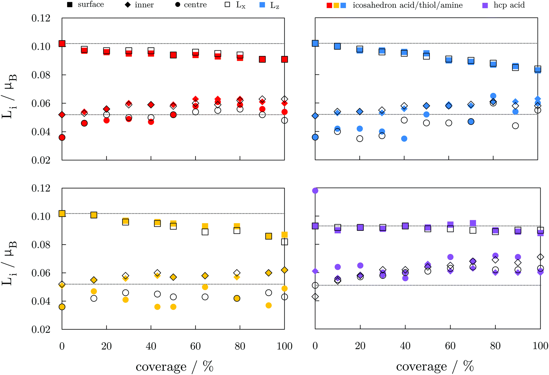 | ||
| Fig. 5 Average orbital moments for three segments (centre ●, inner ◆, surface ■) of ligand-protected Co NPs as a function of the ligand coverage. Two directions of magnetisation are shown as empty and filled symbols, with colours representing varying ligands on icoahedral and hcp Co cores (red, yellow, and blue: acid, thiol, and amine-protected icosahedron, purple: acid-protected hcp Co NP). Dotted lines are average surface and inner orbital moments of bare NPs. | ||
The absence of change in the absolute magnetisation and the Lz − Lx ∝ Ez − Ex correlation with the anisotropy energies which was observed for bare NPs indicates that the spin–orbit coupling has a minimal contribution to the MAE changes in the protected NPs. These changes also do not relate to any structural rearrangement of Co atoms caused by the ligand binding, which is shown by the consistent Co–Co distances over the coverages considered, Tables S5–S8, ESI.† On average, Co–Co bonds are shortened or elongated by ±2.0%, and mostly between the inner and surface Co atoms. Modifications in the binding geometry of the ligands are also minimal and arise due to the aforementioned differences in adsorption sites. Hence, considering the invariance in the orbital moments and structural descriptors, the major contribution to the changes in the MAE of functionalised NPs comes from the re-distribution of the electron density. Here, the nature of the bond between the ligand and metal atoms plays a critical role.
The electronic properties of a single Co–molecule pair for all three ligand types considered are shown in Fig. 6 in the form of projected densities of state, DOS, and the change in electron density induced from the binding of the molecule, Δρ. The difference in electron density was calculated as:
| Δρ = ρCoNLM − (ρCoN + ρM×L) |
 | ||
| Fig. 6 Left: Projected densities of state, DOS, for a single molecule of acetic acid (red), ethanamine (blue), and ethanethiol (yellow) interacting with a 55-atom icosahedral Co NP. Both majority and minority spins are shown. DOS of the surface Co atoms interacting with the molecule are shown as filled blocks, while DOS of the inner Co atom directly beneath the interaction site are shown as dotted lines. Right: Radial probability density function of the difference in electron density induced from the binding of the ligand molecules as a function of the distance from the centre, d. Vertical dashed line corresponds to the position of the surface Co atoms relative to the central atom, and colours correspond to those of ligands’ DOS. | ||
| Ligand-NP pair | Magnetic moment per ligand | Charge per ligand |
|---|---|---|
| Carboxylic acid–icosahedron | 0.089 | −0.643 |
| Amine–icosahedron | 0.050 | −0.482 |
| Thiol–icosahedron | 0.055 | −0.478 |
| Carboxylic acid–hcp | 0.081 | −0.633 |
For the carboxylic acids interacting with the hcp NP, changes in the d-band centre energy are similar in nature to the change induced on the icosahedron, regardless of the arrangement over the NP surfaces. The DOS for the two surfaces are shown in Fig. S5, ESI.† The majority spin d-band energy centre of the bare hcp NP is at −2.16 eV, and that of minority spin is found at −0.38 eV. For the (0001) surface atoms that bind the ligand molecule, those energies are altered to −2.18 and −0.33 eV, respectively, whereas the calculated d-band centre energies for the interacting cobalt atoms of the (101) surface are found at −2.11 and −0.25 eV. The overall effect of the ligand is, hence, unchanged with the position of adsorption, and cumulatively all the ligand molecules contribute to the shift of the minority spin d-band centre towards the Fermi level. The opposite effect of the carboxylic acid protective coating on the MAE values of icosahedral and hcp Co NPs then clearly has to come from the directional adsorption of the ligand molecules. Favoured adsorption positions on the hcp NP are either parallel or perpendicular to the x- and/or z-axis, while compact folding of (111) facets in the icosahedral morphology does not allow for such directional arrangement of ligands, which facilitates reversed MAE performance.
Conclusions
Utilising the chemistry of established interactions between functionalising ligands and magnetic nanoparticles which affect the NPs’ properties can be a robust way to tune the desired magnetic behaviour of the resulting nanocomposites. Amine and thiol functionalisation results in a significant reduction of the total magnetisation of Co NPs, whereas the increasing trend of the magnetic anisotropy energy progresses at a notably slower pace for amine than for thiol functional groups. In contrast, carboxylic acid-protected Co NPs show an increase in magnetic moments and high magnetic anisotropy energies for both icosahedral and hcp morphologies.Descriptors of ligand binding have captured shifts of the minority spin d-band centre energy as the most prominent difference between the three ligand families. While the amine-mediated shift was minimal, those induced through thiol and acid binding were of similar intensity, but of opposite sign, indicating that change in either direction is beneficial to enhance the MAE of icosahedral Co NPs. However, to achieve high MAE values and maintain the favourable magnetisation of bare Co NPs, the positive shift mediated through carboxylic acid interactions is the best out of the options considered here.
Given the important role of biocompatibility-inducing ligands in the magnetic behaviour of protected Co NPs, our work has shown that theoretical insights of such phenomena can boost the targeted design of nanomaterials with favourable magnetic moments and anisotropy energies.
Conflicts of interest
There are no conflicts to declare.Acknowledgements
BF is grateful to Cardiff University for support through a Research Scholarship from the School of Chemistry. We acknowledge the Engineering and Physical Sciences Research Council (Grant No. EP/R512503/1 and EP/K009567/2) for funding. This work was performed using the computational facilities of the Advanced Research Computing @ Cardiff\(ARCCA) Division, Cardiff University. Via our membership of the UK's HPC Materials Chemistry Consortium, which is funded by EPSRC (EP/L000202), this work made use of the facilities of ARCHER, the UK's national high-performance computing service. Information on the data underpinning the presented results, including how to access them, can be found in the Cardiff University data catalogue at DOI: 10.17035/d.2021.0129122354.References
- A. H. Lu, E. L. Salabas and F. Schüth, Angew. Chem., Int. Ed., 2007, 46, 1222–1244 CrossRef CAS PubMed.
- A. H. Latham and M. E. Williams, Acc. Chem. Res., 2008, 41, 411–420 CrossRef CAS PubMed.
- A. J. Cole, V. C. Yang and A. E. David, Trends Biotechnol., 2011, 29, 323–332 CrossRef CAS PubMed.
- P. Guardia, A. Labarta and X. Batlle, J. Phys. Chem. C, 2011, 115, 390–396 CrossRef CAS.
- A. G. Kolhatkar, A. C. Jamison, D. Litvinov, R. C. Willson and T. R. Lee, Int. J. Mol. Sci., 2013, 14, 15977–16009 CrossRef PubMed.
- Z. Karimi, L. Karimi and H. Shokrollahi, Mater. Sci. Eng., C, 2013, 33, 2465–2475 CrossRef CAS PubMed.
- R. A. Bohara, N. D. Thorat and S. H. Pawar, RSC Adv., 2016, 6, 43989–44012 RSC.
- N. A. Frey, S. Peng, K. Cheng and S. Sun, Chem. Soc. Rev., 2009, 38, 2532–2542 RSC.
- Y. Zhu, et al. , ChemCatChem, 2010, 2, 365–374 CrossRef CAS.
- H. Wang, et al. , J. Phys. Chem. C, 2015, 119, 26020–26028 CrossRef CAS.
- S. C. McBain, H. H. P. Yiu and J. Dobson, Int. J. Nanomed., 2008, 3, 169–180 CAS.
- V. V. Mody, et al. , Appl. Nanosci., 2014, 4, 385–392 CrossRef CAS.
- Q. A. Pankhurst, J. Connolly, S. K. Jones and J. A. Dobson, J. Phys. D: Appl. Phys., 2003, 36, R167–R181 CrossRef CAS.
- B. Jeyadevan, J. Ceram. Soc. Jpn., 2010, 118, 391–401 CrossRef CAS.
- S. Laurent, S. Dutz, U. O. Häfeli and M. Mahmoudi, Adv. Colloid Interface Sci., 2011, 166, 8–23 CrossRef CAS PubMed.
- A. E. Deatsch and B. A. Evans, J. Magn. Magn. Mater., 2014, 354, 163–172 CrossRef CAS.
- K. Maier-Hauff, et al. , J. Neurooncol., 2011, 103, 317–324 CrossRef PubMed.
- Z. Nemati, et al. , J. Phys. Chem. C, 2016, 120, 8370–8379 CrossRef CAS.
- A. Espinosa, et al. , ACS Nano, 2016, 10, 2436–2446 CrossRef CAS PubMed.
- E. E. Carpenter, J. Magn. Magn. Mater., 2001, 225, 17–20 CrossRef CAS.
- L. Kafrouni and O. Savadogo, Prog. Biomater., 2016, 5, 147–160 CrossRef CAS PubMed.
- M. Zeisberger, et al. , J. Magn. Magn. Mater., 2007, 311, 224–227 CrossRef CAS.
- A. H. Habib, C. L. Ondeck, P. Chaudhary, M. R. Bockstaller and M. E. McHenry, J. Appl. Phys., 2008, 103, 07A307 CrossRef.
- M. Respaud, et al. , Phys. Rev. B: Condens. Matter Mater. Phys., 1998, 57, 2925–2935 CrossRef CAS.
- B. Farkaš and N. H. de Leeuw, Nanotechnology, 2020, 31, 195711 CrossRef PubMed.
- S. Datta, et al. , Phys. Rev. B: Condens. Matter Mater. Phys., 2007, 76, 014429 CrossRef.
- J. L. Rodríguez-López, F. Aguilera-Granja, K. Michaelian and A. Vega, Phys. Rev. B: Condens. Matter Mater. Phys., 2003, 67, 174413 CrossRef.
- T. Ichii, T. Fukuma, K. Kobayashi, H. Yamada and K. Matsushige, Appl. Surf. Sci., 2003, 210, 99–104 CrossRef CAS.
- P. Crespo, et al. , Phys. Rev. Lett., 2004, 93, 087204 CrossRef CAS PubMed.
- C. Vericat, M. E. Vela, G. Benitez, P. Carro and R. C. Salvarezza, Chem. Soc. Rev., 2010, 39, 1805–1834 RSC.
- O. Margeat, C. Amiens, B. Chaudret, P. Lecante and R. E. Benfield, Chem. Mater., 2005, 17, 107–111 CrossRef CAS.
- V. A. de la Peña O'Shea, I. d. P. R. Moreira, A. Roldán and F. Illas, J. Chem. Phys., 2010, 133, 024701 CrossRef PubMed.
- J. D. Burton and E. Y. Tsymbal, Phys. Rev. B: Condens. Matter Mater. Phys., 2009, 80, 174406 CrossRef.
- K. D. Kwon, et al. , Phys. Rev. B: Condens. Matter Mater. Phys., 2011, 83, 064402 CrossRef.
- M. S. Kuklin and A. J. Karttunen, J. Phys. Chem. C, 2018, 122, 24949–24957 CrossRef CAS PubMed.
- P. Jiang, L. Kang, X. Zheng, Z. Zeng and S. C. Sanvito, Phys. Rev. B, 2020, 102, 195408 CrossRef CAS.
- S. Ener, et al. , Acta Mater., 2019, 165, 270–277 CrossRef CAS.
- L. Puerta, et al. , J. Phys. Chem. A, 2008, 112, 9771–9783 CrossRef CAS PubMed.
- C. Gonzalez, Y. Simón-Manso, M. Marquez and V. C. Mujica, J. Phys. Chem. B, 2006, 110, 687–691 CrossRef CAS PubMed.
- M. J. Hartmann, J. E. Millstone and H. Häkkinen, J. Phys. Chem. C, 2016, 120, 20822–20827 CrossRef CAS.
- M. J. Hartmann, J. E. Millstone and H. Häkkinen, Phys. Chem. Chem. Phys., 2018, 20, 4563–4570 RSC.
- J. M. Pingarrón, P. Yáñez-Sedeño and A. González-Cortés, Electrochim. Acta, 2008, 53, 5848–5866 CrossRef.
- S. Zeng, et al. , Plasmonics, 2011, 6, 491–506 CrossRef CAS.
- N. Wu, et al. , Nano Lett., 2004, 4, 383–386 CrossRef CAS.
- S. M. Ansari, et al. , Appl. Surf. Sci., 2017, 414, 171–187 CrossRef CAS.
- Y. Lu, X. Lu, B. T. Mayers, T. Herricks and Y. Xia, J. Solid State Chem., 2008, 181, 1530–1538 CrossRef CAS.
- H. Khurshid, et al. , J. Appl. Phys., 2015, 117, 17A337 CrossRef.
- L. M. Bauer, S. F. Situ, M. A. Griswold and A. C. S. Samia, Nanoscale, 2016, 8, 12162–12169 RSC.
- P. Campiglio, et al. , New J. Phys., 2015, 17, 063022 CrossRef.
- G. Kresse and J. Furthmüller, Comput. Mater. Sci., 1996, 6, 15–50 CrossRef CAS.
- J. P. Perdew, K. Burke and M. Ernzerhof, Phys. Rev. Lett., 1996, 77, 3865–3868 CrossRef CAS PubMed.
- C. Jo and J. Il Lee, J. Magn. Magn. Mater., 2009, 321, 47–51 CrossRef CAS.
- M. J. Piotrowski, P. Piquini, M. M. Odashima and J. L. F. Da Silva, J. Chem. Phys., 2011, 134, 134105 CrossRef PubMed.
- Y. Sun, S. Liu, X. Guo and S. Huang, Comput. Theor. Chem., 2019, 1154, 11–16 CrossRef CAS.
- G. Kresse and D. Joubert, Phys. Rev. B: Condens. Matter Mater. Phys., 1999, 59, 1758–1775 CrossRef CAS.
- S. Grimme, S. Ehrlich and L. Goerigk, J. Comput. Chem., 2011, 32, 1456–1465 CrossRef CAS PubMed.
- G. Henkelman, A. Arnaldsson and H. Jónsson, Comput. Mater. Sci., 2006, 36, 354–360 CrossRef.
- R. Wu and A. J. Freeman, J. Magn. Magn. Mater., 1999, 200, 498–514 CrossRef CAS.
- G. H. O. Daalderop, P. J. Kelly and M. F. H. Schuurmans, Phys. Rev. B: Condens. Matter Mater. Phys., 1990, 41, 11919–11937 CrossRef CAS PubMed.
- D. Hobbs, G. Kresse and J. Hafner, Phys. Rev. B: Condens. Matter Mater. Phys., 2000, 62, 11556–11570 CrossRef CAS.
- M. Marsman and J. Hafner, Phys. Rev. B: Condens. Matter Mater. Phys., 2002, 66, 224409 CrossRef.
- C. Kittel, Introduction to Solid State Physics, Willey & Sons, New Jersey, 2010 Search PubMed.
- J. Wang, J. M. Albina, T. Iwasaki, H. Moriya and Y. Umeno, J. Mater. Res., 2013, 28, 1559–1566 CrossRef CAS.
- S. Halilov, A. Y. Perlov, P. Oppeneer, A. Yaresko and V. Antonov, Phys. Rev. B: Condens. Matter Mater. Phys., 1998, 57, 9557–9560 CrossRef CAS.
- D. M. Paige, B. Szpunar and B. K. Tanner, J. Magn. Magn. Mater., 1984, 44, 239–248 CrossRef CAS.
- D. Weller, G. R. Harp, R. F. C. Farrow, A. Cebollada and J. Sticht, Phys. Rev. Lett., 1994, 72, 2097–2100 CrossRef CAS PubMed.
- T. Suzuki, et al. , Appl. Phys. Lett., 1994, 64, 2736–2738 CrossRef CAS.
- T. O. Strandberg, C. M. Canali and A. H. MacDonald, Phys. Rev. B: Condens. Matter Mater. Phys., 2005, 73, 144415 CrossRef.
- P.-A. Lindgård and P. V. Hendriksen, Phys. Rev. B: Condens. Matter Mater. Phys., 1994, 49, 12291–12294 CrossRef PubMed.
- M. Jamet, et al. , Phys. Rev. B: Condens. Matter Mater. Phys., 2000, 62, 493–499 CrossRef CAS.
- I. Hrianca, C. Caizer and Z. Schlett, J. Appl. Phys., 2002, 92, 2125–2132 CrossRef CAS.
- R. Moreno, et al. , Sci. Rep., 2020, 10, 2722 CrossRef CAS PubMed.
- M. Jamet, et al. , Phys. Rev. B: Condens. Matter Mater. Phys., 2004, 69, 024401 CrossRef.
- R. A. Guirado-López and J. M. Montejano-Carrizales, Phys. Rev. B: Condens. Matter Mater. Phys., 2007, 75, 184435 CrossRef.
- J. P. Chen, C. M. Sorensen and K. J. Klabunde, Phys. Rev. B: Condens. Matter Mater. Phys., 1995, 51, 527–533 Search PubMed.
- L. He and C. Chen, Phys. Rev. B: Condens. Matter Mater. Phys., 2007, 75, 184424 CrossRef.
- P. Wang, B. Huang, Y. Dai and M. H. Whangbo, Phys. Chem. Chem. Phys., 2012, 14, 9813–9825 RSC.
- I. Barke, et al. , Nat. Commun., 2015, 6, 6187 CrossRef CAS PubMed.
- F. Tournus, K. Sato, T. Epicier, T. J. Konno and V. Dupuis, Phys. Rev. Lett., 2013, 110, 055501 CrossRef CAS PubMed.
- F. Masini, et al. , Phys. Chem. Chem. Phys., 2014, 16, 26506–26513 RSC.
- S. Oyarzún, A. Tamion, F. Tournus, V. Dupuis and M. Hillenkamp, Sci. Rep., 2015, 5, 14749 CrossRef PubMed.
- R. Morel, A. Brenac, C. Portemont, T. Deutsch and L. Notin, J. Magn. Magn. Mater., 2007, 308, 296–304 CrossRef CAS.
- M. Martins and W. Wurth, J. Phys.: Condens. Matter, 2016, 28, 503002 CrossRef PubMed.
- J. Dorantes-Dávila and H. Dreyssé, Phys. Rev. B: Condens. Matter Mater. Phys., 1997, 55, 15033–15042 CrossRef.
- R. A. Guirado-López, J. Dorantes-Dávila and G. M. Pastor, Phys. Rev. Lett., 2003, 90, 226402 CrossRef PubMed.
- S. Rives, et al. , Phys. Rev. B: Condens. Matter Mater. Phys., 2008, 77, 085407 CrossRef.
- M. Pellarin, et al. , Chem. Phys. Lett., 1994, 217, 349–356 CrossRef CAS.
- T. D. Klots, B. J. Winter, E. K. Parks and S. J. Riley, J. Chem. Phys., 1991, 95, 8919–8930 CrossRef CAS.
- T. Rapps, R. Ahlrichs, E. Waldt, M. M. Kappes and D. Schooss, Angew. Chem., Int. Ed., 2013, 52, 6102–6105 CrossRef CAS PubMed.
- L. Meziane, et al. , Nanoscale, 2016, 8, 18640–18645 RSC.
- V. A. De La Peña O'Shea, P. R. De la Piscina, N. Homs, G. Aromí and J. L. G. Fierro, Chem. Mater., 2009, 21, 5637–5643 CrossRef.
- J. Ahmed, S. Sharma, K. V. Ramanujachary, S. E. Lofland and A. K. Ganguli, J. Colloid Interface Sci., 2009, 336, 814–819 CrossRef CAS PubMed.
- V. V. Matveev, et al. , Chem. Phys. Lett., 2006, 422, 402–405 CrossRef CAS.
- K. S. Rao, T. Balaji, Y. Lingappaa, M. R. P. Reddy and T. L. Prakash, J. Exp. Nanosci., 2013, 8, 162–170 CrossRef CAS.
- B. Farkaš, U. Terranova and N. H. de Leeuw, Phys. Chem. Chem. Phys., 2020, 22, 985–996 RSC.
- L. G. Wang, E. Y. Tsymbal and S. S. Jaswal, Phys. Rev. B: Condens. Matter Mater. Phys., 2004, 70, 075410 CrossRef.
- G. Lozano-Blanco and A. J. Adamczyk, Surf. Sci., 2019, 688, 31–44 CrossRef CAS.
- J. J. Sims, C. A. Ould Hamou, R. Réocreux, C. Michel and J. B. Giorgi, J. Phys. Chem. C, 2018, 122, 20279–20288 CrossRef CAS.
- A. Mondal, S. Q. Wu, O. Sato and S. Konar, Chem. – Eur. J., 2020, 26, 4780–4789 CrossRef CAS PubMed.
- D. Shao, S. L. Zhang, L. Shi, Y. Q. Zhang and X. Y. Wang, Inorg. Chem., 2016, 55, 10859–10869 CrossRef CAS PubMed.
- W. B. Sun, et al. , Chem. Sci., 2016, 7, 684–691 RSC.
- B. Farkaš, U. Terranova and N. H. de Leeuw, J. Mater. Chem. B, 2021, 9, 4915–4928 RSC.
Footnote |
| † Electronic supplementary information (ESI) available. See DOI: 10.1039/d1nr01081f |
| This journal is © The Royal Society of Chemistry 2021 |