 Open Access Article
Interfacial magnetism in a fused superatomic cluster [Co6Se8(PEt3)5]2†
Dinesh
Bista
 ,
Turbasu
Sengupta
 ,
Arthur C.
Reber
 and
Shiv N.
Khanna
 *
*
Department of Physics, Virginia Commonwealth University, Richmond, VA 23284-2000, USA. E-mail: Snkhanna@vcu.edu
First published on 10th September 2021
Abstract
An isolated Co6Se8(PEt3)6 cluster is non-magnetic; however, we find that a magnetic unit can be formed by fusing two Co6Se8(PEt3)5 superatoms into a [Co6Se8(PEt3)5]2 dimer. Theoretical studies indicate that the dumbbell-shaped [Co6Se8(PEt3)5]2 dimer has a spin moment of 2μB, and the spin density is primarily localized at the interfacial Co-sites where two clusters are fused into a dimer. The dimer has a low ionization energy of 4.17 eV, allowing the dimer to donate charge to C70 during the formation of a cluster assembled material, as seen in recent experiments by Nuckolls and co-workers. The donation of charge causes the dimer's magnetic moment to drop from 2μB to 1μB. We hypothesize that adding electrons to the dimer, such as doping impurities to the crystal lattice, may enhance the magnetic moment by neutralizing the charged cluster. This reveals a strategy for stabilizing magnetic moments in ligated cluster assemblies.
1. Introduction
Ligated metal chalcogenide clusters have emerged as a new class of superatoms that have attracted considerable interest.1–7 The most common central cores of metal–chalcogenide clusters have a composition of TM6X8(L)6 (TM: transition metal, X: chalcogen, L: ligand). These building blocks are highly stable, can be prepared in solution, and are redox-active, allowing the formation of ionic cluster assembled solids with various complementary units.4–10 These interesting classes of solids were initially reported by Roy et al.,4–10 who synthesized three such solids, including [Co6Se8(PEt3)6][C60]2, [Cr6Te8(PEt3)6][C60]2, and [Ni9Te6(PEt3)8][C60]. In each case, the core consists of chalcogenide-based clusters decorated with 6 or 8 triethylphosphine (PEt3) ligands connected to the metal atoms, thus protecting the sensitive metallic core. In the solid phase, the ligated clusters donate charge to C60, which acts as charge acceptor to form an ionic assembly analogous to CdI2 or NaCl class of ionic salts.6 Recent theoretical investigations have revealed that the ligands protect the metallic cores and control the electronic and magnetic properties.11–19 For example, the attachment of donor PEt3 ligands lowers the ionization energies leading to clusters with ionization energies even lower than the conventional alkali atoms.17 Donation of charge to counterions then promotes the formation of stable crystalline solids through ionic cluster assemblies.20–23The attached ligands generally protect the clusters and promote the formation of the ionic solids; however, the ligands may also lead to other outcomes. For example, PEt3 ligands quench the magnetic moment of the transition metal atoms, while the unligated metal cores usually possess a higher magnetic moment.24 Thus, it is important to ask if there is a way to protect the metal–chalcogenide cluster with ligands while also stabilizing the respective magnetic state. In this work, we show that by fusing two ligated superatomic clusters, one can form a dimer with a magnetic moment localized at the interface between the fused clusters.25–28 We demonstrate this intriguing possibility by considering the metal–chalcogenide cluster-core of Co6Se8 with PEt3 ligands. The addition of six PEt3 ligands to the Co-sites quenches the spin magnetic moment of the cluster.
In contrast, removing the PEt3 ligands can restore the spin moment. However, the unligated cluster becomes unstable. One way to overcome this problem is to join two Co6Se8(PEt3)5 clusters into a composite [Co6Se8(PEt3)5]2 unit through covalent bonding between Co and Se sites on different clusters. Here we show that such a composite cluster has a finite spin moment localized at the interfacial sites, thus offering a unique opportunity for a tunable spin magnetic moment in a ligand protected cluster. Additionally, these magnetic units can also be arranged into a magnetic cluster assembly.
Our investigations are inspired by the recent experimental work by Nuckolls et al.,29 who have stabilized metal–chalcogenide dimers, [Co6Se8(PEt3)5]2 with C70− dimers forming a cluster assembled solid. As pointed out by Nuckolls et al.29 the dimers’ elongated shapes allow the facile synthesis of novel solids that pack these dumbbell-shaped composite metal–chalcogenide clusters with other dumbbell-shaped C140 counterions to form stable anisotropic solids. The toluene solvent fills the space between the dumbbell-shaped chalcogenide-dimers and C140. Furthermore, the shape allows the generation of multiple assemblies with differing atomic arrangements of these ionic cluster solids formed from [Co6Se8(PEt3)5]2+ cations and C1402− anions. In addition to the investigation of the magnetic character, we also analyze the role of charge transfer on the stability of the cluster assembled solid. We find large cohesive energy of the cluster assembled material demonstrating a significant stabilization during the formation of the material. This stabilization is caused by charge transfer from the metal–chalcogenide dimers to the fullerenes. Hence, the material is stabilized via ionic bonding. The nature of electronic states characterizing the HOMO (highest occupied molecular orbital) and LUMO (lowest unoccupied molecular orbital) was analyzed to understand how this charge transfer affects the spin magnetic moment of the metal–chalcogenide dimers.
2. Results
2.1. Effect of ligands on the magnetic properties of a Co6Se8(PEt3)n (n = 0–6) cluster and dimer formation
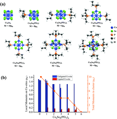
We present a brief review of the ligand effects on a Co6Se8 cluster's spin-magnetic moment. The ground-state structure of Co6Se8 consists of an octahedron of 6 Co-sites with faces decorated with 8 Se-atoms, as shown in Fig. 1a. The cluster has a spin magnetic moment of 10 μB. The average Co–Se bond is around 2.39 Å, and each Co-site carries a local spin magnetic moment of approximately 1.5μB. All cluster structures were fully optimized without constraints. The successive additions of PEt3 ligands decrease the total magnetic moment monotonically, thereby completely quenching the magnetic moment for the fully ligated cluster, as seen in Fig. 1b. The local spin-moments reduce drastically after the ligation on the Co-sites, also seen in Fig. 1b. The magnetic moments on the Co-sites decrease from 1.5μB to 0μB once the PEt3 ligand is attached. A detailed electronic structure investigation reveals that the ligand states bind with the d-states of the Co-sites that lead to a filling of minority states resulting in a decrease in the local moment, as shown in our previous work.24These results suggest that one way to create a magnetic cluster is to remove one or more ligands; however, losing the ligand exposes the metal-sites to reactants. Such unligated species are likely to be transient. One strategy for stabilizing such magnetic clusters is to fuse two ligated metal–chalcogenide clusters where the exposed metal ions bind to the chalcogen on the other cluster, making the system stable. When two Co6Se8(PEt3)5 clusters, each with one missing ligand, combine through the unligated Co-sites of one cluster with the Se-sites of the other, they form a composite superatomic dimer [Co6Se8(PEt3)5]2, as shown in Fig. 2. This dimer could result in a magnetic species with no exposed metal sites and enhanced stability. The ligated dimer is protected from exposure; however, the lack of a closed electronic shell and numerous phosphine ligands means that such dimers will likely be excellent charge donors and become cations when forming the cluster assembled solids.
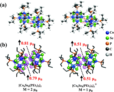
We investigated the atomic and electronic structure of [Co6Se8(PEt3)5]2 using theoretical methods. Fig. 2 shows the dumbbell-shaped ground state structure of [Co6Se8(PEt3)5]2, which has a spin magnetic moment of 2μB. The Adiabatic Ionization Potential (AIP) of the dimer is only 4.17 eV, slightly less than that of a K atom,30 showing that it is a suitable donor. Since the cluster is expected to donate charge while forming an ionic solid, we also calculated the spin magnetic moment of the cationic species and found it to be 1μB. The spin densities for both neutral and cationic dimers are localized at the interfacial Co-atoms that lie at the junction between the fused clusters without any PEt3 ligand attached to them, as seen in the isosurfaces in Fig. 2b. The localization of the spin densities at the interface is due to the presence of dangling bonds on the Co atoms at the junction whose spin magnetic moment is quenched when ligated by the phosphine, but not by the Se of the adjacent cluster. For neutral dimer, Co-atoms at the junction have local spin moments of 0.81μB and 0.79μB, while the other 10 Co-atoms contribute small spin moments to make a total 2μB magnetic moment. Thus, we have a magnetic moment on the unligated Co-sites at the interface while still protecting the interfacial Co-atoms from the reactivity.
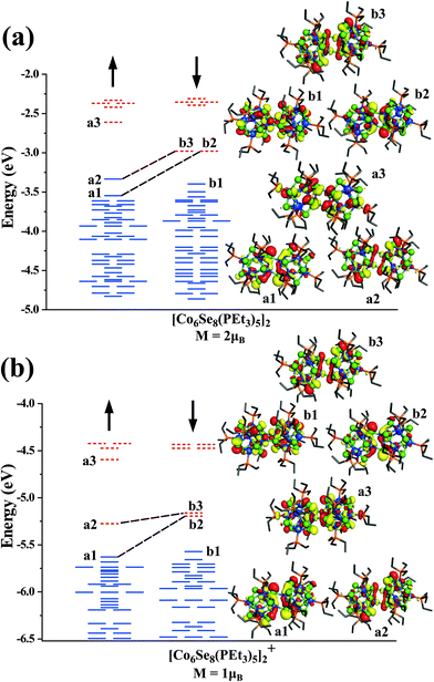
To gain more insight into the nature of states contributing to the moment, we show in Fig. 3, the one-electron levels in the neutral and cationic dimers. The ground state of the neutral cluster is marked by a pair of d-states a1 and a2 (Dyz/Dxz and Dz2) in the majority spin states that are unoccupied in the minority spin states (b2 and b3), as shown in Fig. 3a. These states correspond to the d-states of the interfacial Co-atoms and are responsible for the spin magnetic moment of 2μB. The HOMO level is in the majority spin, while the LUMO level is in the minority manifold. However, when the dimer becomes cationic, the HOMO level shifts to the minority spin channel, and the LUMO level shifts to the majority spin states, as shown in Fig. 3b. We also analyzed the electronic states to examine the stability of clusters. The neutral and cationic species are marked by HOMO–LUMO gaps of 0.35 and 0.30 eV, respectively.
Additionally, we found that the magnetic moment of the dimer with +2 oxidation state is also 2μB. It is interesting to note that both neutral and +2 state has a magnetic moment of 2μB, while the cationic dimer has the spin magnetic moment of 1μB. Since a pair of unfilled minority states characterize the neutral species, one may ask if filling those states would complete the electronic shell and lead to an electronically stable cluster. To explore this possibility, we investigated the electronic structure of a [Co6Se8(PEt3)5]22− cluster. The cluster is found to be non-magnetic with electronic shell-closure and a larger HOMO–LUMO gap of 0.53 eV, indicative of an electronically stable species, as shown in ESI Fig. 1.†
2.2. Cluster assembled solid
As mentioned earlier, Nuckolls et al.29 have recently synthesized a cluster assembled solid by combining [Co6Se8(PEt3)5]2 dimers with C140 motifs composed of two-linked C70 clusters.29 Both [Co6Se8(PEt3)5]2 and C140 are observed to have dumbbell-shaped structures, and unfilled interstitial space is filled by toluene solvent molecules. They have synthesized three different cluster-assembled solids made from [Co6Se8(PEt3)5]2 and the C70 dimers(C140), using different stoichiometry of toluene molecules. Initially, we start with investigating the redox properties of the cluster building blocks to understand the formation of this cluster assembled solid. The [Co6Se8(PEt3)5]2 dimers have a low AIP of 4.17 eV and donate charge to the C70, which has a large electron affinity of 2.86 eV, as shown in ESI Fig. 2.† The 1e− energy levels of the [Co6Se8(PEt3)5]2 dimer and C70 are plotted side by side in ESI Fig. 3† indicate that the HOMO of the [Co6Se8(PEt3)5]2 dimer is higher than the LUMO of the C70.Hence, the electron transfer from the dimer to the C70 is energetically favorable. The radical C70− anions formed have HOMO–LUMO gaps of only 0.12 eV and are highly reactive. Hence, the C70− anions combine to form the dimer C1402−, that has a closed electronic shell and a large HOMO–LUMO gap of 0.73 eV, as shown in ESI Fig. 4.†
We next examined the electronic structure of one of the crystal structures from the experiment29 to understand how the electronic structure of the metal chalcogenide-dimers evolves as they form the observed cluster-assembled solid. We studied the crystal structure of the solid with the stoichiometry of {[Co6Se8(PEt3)5]2(Toluene)2C140}2 in the unit cell, and the details of the calculations are noted in the Methods section. The crystal structure was fully optimized without constraints. The shortest distance between atoms in the nearest C140 dimers is found to be 6.1 Å. Fig. 4 shows the unit cell and an isosurface of the electron spin density. Note that the spin density is localized on the interface between the fused clusters, as seen in Fig. 4b. The magnetic moment on each dimer is found to be 1μB; however, the coupling between the four dimers in the unit cell is antiferromagnetic. This antiferromagnetic arrangement is only 0.03 eV more stable than the ferromagnetic state, which displays the magnetic moment of 1μB per dimer or 4μB per unit cell. The schematic of the antiferromagnetic and ferromagnetic couplings between the dimers in the solid is given in ESI Fig. 5.† Besides the energies being very close for the antiferromagnetic and ferromagnetic couplings, the bandgap energies are also almost equal with the values of 0.24 eV for each. We know that the spin magnetic moments of the neutral and cationic dimers are 2μB and 1μB, respectively, from our free cluster calculations. Hence, the dimers in the solid with 1μB can be best described as cations, [Co6Se8(PEt3)5]2+. To confirm this, we did a Bader analysis of the charge density and found a charge transfer of a 0.81e− from each [Co6Se8(PEt3)5]2-dimer units to the C140 units, as seen in Table 1. It confirms that the dimers are in the cationic state, and the C140 are also best described as C1402−. These theoretical calculations verify the experimental inference of charge transfer between the dimers and the fullerene units.29 The stabilization of the cluster assembly due to charge transfer is confirmed by an energy analysis that gives the cohesive energy of the unit cell to be 26.68 eV. The cohesive energy is calculated by eqn (1),
| Ecohesive = Esolid − 4E[Co6Se8(PEt3)5]2 − 4EC70− 4ETol | (1) |
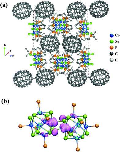 | ||
| Fig. 4 (a) The optimized unit cell structure of {[Co6Se8(PEt3)5]2(Toluene)2C140}2 crystal. (b) The spin density isosurface of the dimer unit. | ||
| Units | Charges | Total number of units | Total-Charge |
|---|---|---|---|
| Cluster | 0.8056 | 4 | 3.2224 |
| C140 | −1.6174 | 2 | −3.2348 |
| Toluene | 0.00297 | 4 | 0.0119 |
E solid, E[Co6Se8(PEt3)5]2, EC70, and ETol represent the energies of solid, [Co6Se8(PEt3)5]2, C70, and toluene molecules, respectively in eqn (1). To investigate further, we have calculated the removal energy of individual components in the solid. The removal energy is computed as the energy difference between the optimized {[Co6Se8(PEt3)5]2(Toluene)2C140}2 crystal and the optimized solid without the respective component. We found that the toluene's removal energy is 0.97 eV per molecule, and this comes to 3.88 eV for the four molecules in the unit cell. For comparison, the removal energies of the (C70)2 and [Co6Se8(PEt3)5]2 are found to be 9.66 and 7.72 eV, respectively. These large removal energies confirm that there is ionic interaction holding the material together. An alternative way of looking at this is that the cohesive energy of the cluster assembled material per electron transfer from the dimer to the C70 is 6.67 eV, as there are 4 electron transfers per unit cell. For comparison, the cohesive energy for NaCl is ∼8.19 eV per electron transfer,31,32 so the value is in the range expected for an ionic solid. The 6.67 eV cohesive energy combines several factors; in addition to the electron transfer, the bonding that forms the (C70)2 by combining two C70 is also included, as our reference energy is isolated C70. For free clusters, this bond energy is approximately 1.11 eV for combining two C70− into (C70)22−. The result of this dimer formation is a rough estimate since the stability of double anions in free space is much lower than in a solution or in a solid. The cohesive energy of 6.67 eV per electron transfer demonstrates that the present cluster assembled material is not a molecular solid but rather a material held together via ionic bonding.
The projected density of states (PDOS) of metal chalcogenide dimer, fullerene, and toluene within the solid is shown in Fig. 5. The material's bandgap energy is calculated to be 0.24 eV, with the valence band edge composed of the states on the metal–chalcogenide dimer. In contrast, the conduction band edge is mostly localized on the fullerenes (C140). The gap on the metal–chalcogenide dimers is found to be 0.32 eV. The optical bandgap from the experiment is reported to be 0.55 eV, which is higher than the calculated value. Our calculated value is expected to be lower than the experimentally observed value since the valence band edge is found on the metal–chalcogenide while the edge of the conduction band is on the fullerenes so that the band edge excitations may be relatively weak. Furthermore, the density functional theory also tends to underestimate the bandgap energy.33–36
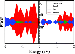 | ||
| Fig. 5 The projected density of state (PDOS) plot including the various components of {[Co12Se16(PEt3)10]2(Toluene)2C140}2 solid. | ||
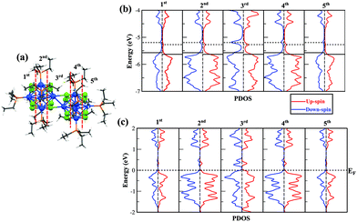
We next want to understand how the electronic structure changes as we move through the fused cluster dimer and are especially interested in the interfacial region where the two clusters are joined. We plotted the local density of states of different regions of the dimer in Fig. 6. The regions correspond to different cross sections of the fused clusters as we move from one terminal end, the 1st and 2nd regions, through the interface, the 3rd region, and on to the other terminal end of the cluster dimer, the 4th and 5th regions. The 1st and 2nd regions are the mirror images of the 5th and 4th regions, respectively, as shown in Fig. 6a. Fig. 6b provides the local density of states of free cationic dimer [Co6Se8(PEt3)5]2+, and Fig. 6c presents the local density of states of the metal–chalcogenide dimer in the cluster assembled solid. In both the free cluster and the solid, we see that the spin is quenched in every region except in the 3rd region that lies at the junction between the fused clusters. In the 3rd region, two unfilled minority states and one unfilled majority impurity states are found, consistent with a spin of 1μB per cluster. This offers additional proof that the spin is localized at the interfacial Co-atoms and that ligands have quenched the spin of Co-atoms at their respective sites. Hence, we have stabilized a ligand protected cluster with a finite magnetic moment at the junction by fusing two clusters. Moreover, we have reconfirmed that the interfacial magnetic moments of the metal–chalcogenide dimers are conserved even after the assembly of the solid.
Next, we consider the effect of adding or removing electrons on the magnetic state of such metal–chalcogenide dimers. The metal–chalcogenide dimers in the solid have +1 charge states with a magnetic moment of 1μB. However, the neutral and +2 states of metal–chalcogenide dimers have a magnetic moment of 2μB. Hence, if an electron can be added to or taken out from the dimers in the solid, then the magnetic moment of the solid can be increased. Fortunately, the controlled doping of impurities in the crystal lattice is possible through chemical synthesis.30 Thus, the addition of electron-donating or electron-withdrawing species to the material might enhance the magnetic moment, offering a cluster assembled material with tunable magnetic properties.37,38 It can be used as a method to enhance the magnetic moment in the ligated cluster assembled materials. We would like to add that in recent experiments,29 the significant electron transport was observed for only one of the three synthesized cluster assembled materials-{[Co6Se8(PEt3)5]1.44(Toluene)2C140}2, where the distance between the C140 chains was only 3.8 Å (the shortest distance between three cluster assembled materials). It was proposed that the conduction in that assembly was through fullerenes. However, it should be possible to induce conduction pathways through chalcogenide clusters39 by appropriate doping. One strategy to induce conductivity through the metal–chalcogen clusters would be to use bidentate aromatic ligands that could connect different clusters or use smaller ligands such as PMe3 to decrease the distance between the clusters. The second strategy could be to use 4d or 5d transition metals as these clusters may be more delocalized than the 3d clusters, resulting in better conduction. However, this may also lead to a change in the spin on the cluster interface. Hence, under circumstances where the conduction is through the metal–chalcogen clusters, the currents will be spin-polarized.
3. Conclusions
To summarize, we have shown that by linking two Co6Se8(PEt3)5 clusters, it is possible to form a composite dimer [Co6Se8(PEt3)5]2 that is magnetic. The spin magnetic moment is primarily localized at the interfacial Co-sites, where the two clusters are fused into a dimer. This means that we have stabilized a ligand protected magnetic cluster by combining two highly stable superatomic clusters. Furthermore, the dumb-bell shaped dimer is marked by low ionization energy of 4.17 eV, which can interact with the similar shaped C140 composed of two C70 units, characterized by a high electron affinity to form a stable ionic solid. Additionally, the theoretical calculations also support the experimental work done by Nuckolls and co-workers,29 who have stabilized the anisotropic solids by using toluene molecules as space fillers. Theoretical studies confirm that the [Co6Se8(PEt3)5]2 dimer loses electrons to C140 in the solid, leaving each metal–chalcogenide dimer as cations. The neutral dimers have a spin moment of 2μB per cluster, while the cationic dimers have spin moments of 1μB. When an electron passes through the metal–chalcogenide dimer, the transient neutrality of the cationic species will favor the higher magnetic state of the neutral dimer. Thus, the cluster-dimer is expected to show an intriguing magnetic characteristic when an electron is added to the system. If the electron is induced through the impurities to the cluster assembled materials, it can be used as a strategy to enhance the magnetic moment and might also lead to spin-polarized current. This situation may be useful for spintronic-related applications.4. Methods
4.1. Theoretical techniques
The studies performed here are based on the first-principles density functional methods using the Amsterdam Density Functional (ADF) program.40 The exchange–correlation functional proposed by Perdew, Burke, and Ernzerhof (PBE), which utilizes the generalized gradient approximation (GGA), was used.41 The Slater type valence triple-ζ basis sets with two polarization functions (TZ2P) basis sets42,43 were used for all the elements with a large frozen electron core. The local minimum for each structure was found using the quasi-Newton method44 without any symmetry restrictions, and the lowest energy structures were determined for all the calculated systems. The SCF convergence criterion was set to 1 × 10⁻⁸ Hartree, whereas the default criteria40 were used for all optimizations. The relativistic effects were incorporated using the zero-order regular approximation (ZORA).45 We have investigated several spin multiplicities to determine the most energetically stable ground state structure for the anionic, neutral, and cationic species.The geometric optimization and the electronic structure calculation of the periodic crystal structure were performed by the projector-augmented wave (PAW) method46,47 as implemented in the Vienna Ab initio Simulation Package (VASP).48,49 The dispersion-corrected density functional theory (DFT) within the generalized gradient approximation (GGA) framework proposed by Perdew, Burke, and Ernzerhof (PBE)41 for the exchange and correlation functional is utilized for all calculations. The DFT-D3 method was used to include the van der Waals corrections.50 The Kohn–Sham orbitals were expanded using a plane-wave basis set, and the cutoff was set to 400 eV. For the VASP48,49 calculations, the crystal structure was fully optimized, and the threshold for the electronic convergence was set to 10−5 eV, whereas 0.01 eV Å−1 was chosen as the criterion for ionic convergence.
Author contributions
D.B, A.C.R., and T.S. conducted all the calculations. S.N.K, A.C.R., T.S., and D.B analyzed the results, and the manuscript was written by S.N.K, A.C.R., T.S., and D.B.Data availability
The structures and data are given in the ESI.† All additional data generated or analyzed during this study are available via request to the corresponding author.Conflicts of interest
The authors declare no competing interests.Acknowledgements
The authors gratefully acknowledge funding by the US Department of Energy (DOE) under the award DE-SC0006420.References
- J. F. Corrigan, O. Fuhr and D. Fenske, Adv. Mater., 2009, 21, 1867–1871 CrossRef CAS.
- C. E. Anson, A. Eichhöfer, I. Issac, D. Fenske, O. Fuhr, P. Sevillano, C. Persau, D. Stalke and J. Zhang, Angew. Chem., Int. Ed., 2008, 47, 1326–1331 CrossRef CAS PubMed.
- C. A. Goddard, J. R. Long and R. H. Holm, Inorg. Chem., 1996, 35, 4347–4354 CrossRef CAS PubMed.
- A. M. Champsaur, J. Yu, X. Roy, D. W. Paley, M. L. Steigerwald, C. Nuckolls and C. M. Bejger, ACS Cent. Sci., 2017, 3, 1050–1055 CrossRef CAS PubMed.
- A. Pinkard, A. M. Champsaur and X. Roy, Acc. Chem. Res., 2018, 51, 919–929 CrossRef CAS PubMed.
- X. Roy, C.-H. Lee, A. C. Crowther, C. L. Schenck, T. Besara, R. A. Lalancette, T. Siegrist, P. W. Stephens, L. E. Brus and P. Kim, Science, 2013, 341, 157–160 CrossRef CAS PubMed.
- B. M. Boardman, J. R. Widawsky, Y. S. Park, C. L. Schenck, L. Venkataraman, M. L. Steigerwald and C. Nuckolls, J. Am. Chem. Soc., 2011, 133, 8455–8457 CrossRef CAS PubMed.
- N. A. Gadjieva, A. M. Champsaur, M. L. Steigerwald, X. Roy and C. Nuckolls, Eur. J. Inorg. Chem., 2020, 2020, 1245–1254 CrossRef CAS.
- C.-H. Lee, L. Liu, C. Bejger, A. Turkiewicz, T. Goko, C. J. Arguello, B. A. Frandsen, S. C. Cheung, T. Medina, T. J. S. Munsie, R. D'Ortenzio, G. M. Luke, T. Besara, R. A. Lalancette, T. Siegrist, P. W. Stephens, A. C. Crowther, L. E. Brus, Y. Matsuo, E. Nakamura, Y. J. Uemura, P. Kim, C. Nuckolls, M. L. Steigerwald and X. Roy, J. Am. Chem. Soc., 2014, 136, 16926–16931 CrossRef CAS PubMed.
- E. J. Telford, J. C. Russell, J. R. Swann, B. Fowler, X. Wang, K. Lee, A. Zangiabadi, K. Watanabe, T. Taniguchi, C. Nuckolls, P. Batail, X. Zhu, J. A. Malen, C. R. Dean and X. Roy, Nano Lett., 2020, 20, 1718–1724 CrossRef CAS PubMed.
- V. Chauhan, A. C. Reber and S. N. Khanna, J. Am. Chem. Soc., 2017, 139, 1871–1877 CrossRef CAS PubMed.
- V. Chauhan, A. C. Reber and S. N. Khanna, J. Phys. Chem. A, 2016, 120, 6644–6649 CrossRef CAS PubMed.
- V. Chauhan, S. Sahoo and S. N. Khanna, J. Am. Chem. Soc., 2016, 138, 1916–1921 CrossRef CAS PubMed.
- A. C. Reber, V. Chauhan and S. N. Khanna, J. Chem. Phys., 2017, 146, 024302 CrossRef PubMed.
- G. Liu, A. Pinkard, S. M. Ciborowski, V. Chauhan, Z. Zhu, A. P. Aydt, S. N. Khanna, X. Roy and K. H. Bowen, Chem. Sci., 2019, 10, 1760–1766 RSC.
- A. C. Reber and S. N. Khanna, Npj Comput. Mater., 2018, 4, 33 CrossRef.
- A. C. Reber, D. Bista, V. Chauhan and S. N. Khanna, J. Phys. Chem. C, 2019, 123, 8983–8989 CrossRef CAS.
- G. Liu, V. Chauhan, A. P. Aydt, S. M. Ciborowski, A. Pinkard, Z. Zhu, X. Roy, S. N. Khanna and K. H. Bowen, J. Phys. Chem. C, 2019, 123, 25121–25127 CrossRef CAS.
- S. T. Akin, V. Zamudio-Bayer, K. Duanmu, G. Leistner, K. Hirsch, C. Bülow, A. Ławicki, A. Terasaki, B. von Issendorff, D. G. Truhlar, J. T. Lau and M. A. Duncan, J. Phys. Chem. Lett., 2016, 7, 4568–4575 CrossRef CAS PubMed.
- S. A. Claridge, A. W. Castleman, S. N. Khanna, C. B. Murray, A. Sen and P. S. Weiss, ACS Nano, 2009, 3, 244–255 CrossRef CAS PubMed.
- S. Mandal, A. C. Reber, M. Qian, P. S. Weiss, S. N. Khanna and A. Sen, Acc. Chem. Res., 2013, 46, 2385–2395 CrossRef CAS PubMed.
- S. Serrano-Guisan, G. di Domenicantonio, M. Abid, J.-P. Abid, M. Hillenkamp, L. Gravier, J.-P. Ansermet and C. Félix, Nat. Mater., 2006, 5, 730–734 CrossRef CAS PubMed.
- A. Turkiewicz, D. W. Paley, T. Besara, G. Elbaz, A. Pinkard, T. Siegrist and X. Roy, J. Am. Chem. Soc., 2014, 136, 15873–15876 CrossRef CAS PubMed.
- G. Liu, V. Chauhan, A. P. Aydt, S. M. Ciborowski, A. Pinkard, Z. Zhu, X. Roy, S. N. Khanna and K. H. Bowen, J. Phys. Chem. C, 2019, 123, 25121–25127 CrossRef CAS.
- A. M. Champsaur, T. J. Hochuli, D. W. Paley, C. Nuckolls and M. L. Steigerwald, Nano Lett., 2018, 18, 4564–4569 CrossRef CAS PubMed.
- A. C. Reber, V. Chauhan, D. Bista and S. N. Khanna, Nanoscale, 2020, 12, 4736–4742 RSC.
- D. Bista, V. Chauhan, T. Sengupta, A. C. Reber and S. N. Khanna, Nanoscale, 2020, 12, 12046–12056 RSC.
- D. Bista, T. Sengupta, A. C. Reber and S. N. Khanna, J. Phys. Chem. A, 2021, 125, 816–824 CrossRef CAS PubMed.
- J. Yang, F. Wang, J. C. Russell, T. J. Hochuli, X. Roy, M. L. Steigerwald, X. Zhu, D. W. Paley and C. Nuckolls, J. Am. Chem. Soc., 2020, 142, 11993–11998 CrossRef CAS PubMed.
- A. Kramida, Y. Ralchenko and J. Reader, NIST Atomic Spectra Database (Ver. 5.7. 1), National Institute of Standards and Technology, Gaithersburg, MD, USA, 2019 Search PubMed.
- M. P. Marder, Condensed matter physics, John Wiley & Sons, 2010 Search PubMed.
- S. Nagasaka and T. Kojima, J. Phys. Soc. Jpn., 1987, 56, 408–414 CrossRef CAS.
- J. P. Perdew, Int. J. Quantum Chem., 1985, 28, 497–523 CrossRef.
- J. M. Crowley, J. Tahir-Kheli and W. A. Goddard III, J. Phys. Chem. Lett., 2016, 7, 1198–1203 CrossRef CAS PubMed.
- H. Xiao, J. Tahir-Kheli and W. A. Goddard III, J. Phys. Chem. Lett., 2011, 2, 212–217 CrossRef CAS.
- H. R. Banjade, J. Pan and Q. Yan, Phys. Rev. Mater., 2021, 5, 014005 CrossRef CAS.
- E. S. O'Brien, M. T. Trinh, R. L. Kann, J. Chen, G. A. Elbaz, A. Masurkar, T. L. Atallah, M. V. Paley, N. Patel, D. W. Paley, I. Kymissis, A. C. Crowther, A. J. Millis, D. R. Reichman, X.-Y. Zhu and X. Roy, Nat. Chem., 2017, 9, 1170 CrossRef PubMed.
- S. N. Khanna and A. C. Reber, Nat. Chem., 2017, 9, 1151–1152 CrossRef CAS PubMed.
- J. Yu, C.-H. Lee, D. Bouilly, M. Han, P. Kim, M. L. Steigerwald, X. Roy and C. Nuckolls, Nano Lett., 2016, 16, 3385–3389 CrossRef CAS PubMed.
- G. te Velde, F. M. Bickelhaupt, E. J. Baerends, C. Fonseca Guerra, S. J. A. van Gisbergen, J. G. Snijders and T. Ziegler, J. Comput. Chem., 2001, 22, 931–967 CrossRef CAS.
- J. P. Perdew, K. Burke and M. Ernzerhof, Phys. Rev. Lett., 1996, 77, 3865–3868 CrossRef CAS PubMed.
- E. Van Lenthe and E. J. Baerends, J. Comput. Chem., 2003, 24, 1142–1156 CrossRef CAS PubMed.
- D. P. Chong, E. Van Lenthe, S. Van Gisbergen and E. J. Baerends, J. Comput. Chem., 2004, 25, 1030–1036 CrossRef CAS PubMed.
- L. Fan and T. Ziegler, J. Chem. Phys., 1991, 95, 7401–7408 CrossRef CAS.
- E. van Lenthe, J. G. Snijders and E. J. Baerends, J. Chem. Phys., 1996, 105, 6505–6516 CrossRef CAS.
- P. E. Blöchl, Phys. Rev. B: Condens. Matter Mater. Phys., 1994, 50, 17953 CrossRef PubMed.
- G. Kresse and D. Joubert, Phys. Rev. B: Condens. Matter Mater. Phys., 1999, 59, 1758 CrossRef CAS.
- G. Kresse and J. Hafner, Phys. Rev. B: Condens. Matter Mater. Phys., 1993, 47, 558–561 CrossRef CAS PubMed.
- G. Kresse and J. Furthmüller, Phys. Rev. B: Condens. Matter Mater. Phys., 1996, 54, 11169–11186 CrossRef CAS PubMed.
- S. Grimme, S. Ehrlich and L. Goerigk, J. Comput. Chem., 2011, 32, 1456–1465 CrossRef CAS PubMed.
Footnote |
| † Electronic supplementary information (ESI) available. See DOI: 10.1039/d1nr00876e |
| This journal is © The Royal Society of Chemistry 2021 |

