
 Open Access Article
 This Open Access Article is licensed under a Creative Commons Attribution-Non Commercial 3.0 Unported Licence
An ion-selective crown ether covalently grafted onto chemically exfoliated MoS2 as a biological fluid sensor†
Anastasios
Stergiou‡
 *a,
Christina
Stangel‡
a,
Ruben
Canton-Vitoria
b,
Ryo
Kitaura
b and
Nikos
Tagmatarchis
*a
*a,
Christina
Stangel‡
a,
Ruben
Canton-Vitoria
b,
Ryo
Kitaura
b and
Nikos
Tagmatarchis
*a
aTheoretical and Physical Chemistry Institute, National Hellenic Research Foundation, 48 Vassileos Constantinou Avenue, 11635 Athens, Greece. E-mail: astergiou@eie.gr; tagmatar@eie.gr
bDepartment of Chemistry, Nagoya University, Nagoya 464-8602, Japan
First published on 12th April 2021
Abstract
We describe the basal plane functionalization of chemically exfoliated molybdenum disulfide (ce-MoS2) nanosheets with a benzo-15-crown-5 ether (B15C5), promoted by the chemistry of diazonium salts en route to the fabrication and electrochemical assessment of an ion-responsive electrode. The success of the chemical modification of ce-MoS2 nanosheets was investigated by infrared and Raman spectroscopy, and the amount of the incorporated crown ether was estimated by thermogravimetric analysis. Raman spatial mapping at on-resonance excitation allowed us to disclose the structural characteristics of the functionalized B15C5-MoS2 nanosheets and the impact of basal plane functionalization to the stabilization of the 1T phase of ce-MoS2. Morphological investigation of the B15C5-MoS2 hybrid was implemented by atomic force microscopy and high-resolution transmission electron microscopy. Furthermore, fast-Fourier-transform analysis and in situ energy dispersive X-ray spectroscopy revealed the crystal lattice of the modified nanosheets and the presence of crown-ether addends, respectively. Finally, B15C5-MoS2 electrodes were constructed and evaluated as ion-selective electrodes for sodium ions in aqueous solution and an artificial sweat matrix.
Introduction
Molybdenum disulfide (MoS2) has a layered crystal structure, in which the trigonal prismatic (2H) coordination of sulfur (S) to molybdenum (Mo) atoms results in quasi-2D crystal nanosheets held together by weak van der Waals interactions forming bulk 2H-MoS2.1,2 The presence of the interlayer spacing has been utilized for the exfoliation of the bulk material towards monolayered nanosheets3–6 and the preparation of MoS2-based intercalation compounds,7–9 advancing the exploration of exfoliated quasi-2D crystals for a series of applications.10,11 Treating the bulk semiconducting 2H-MoS2 with n-butyl lithium (n-BuLi) under dry conditions results in Lix–MoS2, the most common transition metal dichalcogenide intercalated compound. The violent decomposition of Lix–MoS2 in aqueous media affords stable suspensions of monolayered nanosheets, in which the Mo atoms are octahedrally (1T) coordinated, abbreviated as chemically exfoliated MoS2 (ce-MoS2).12,13 Nevertheless, upon drying or annealing of the ce-MoS2 exfoliated layers, an irreversible transformation to the 2H phase occurs.13,14 Notably, the metastable 1T phase of ce-MoS2 emerged as a versatile candidate for the decoration of the basal plane of the exfoliated nanosheets.15,16 Exposure of bulk MoS2 powders to n-BuLi results in an extended electron transfer from the organometallic reagent to the inorganic crystals. The as-prepared Lix–MoS2 can be thus considered as a highly reactive nucleophile and is capable to undergo substitution reactions with organic compounds bearing molecular fragments susceptible to nucleophilic substitution reactions. In this context, the reaction of ce-MoS2 nanosheets with organic halides17 and aryl diazonium salts18,19 proved to facilitate the decoration of the basal plane with organic addends.Monitoring of biological fluids drives the rapid expansion of wearable chemical sensors, which effectively allow the real-time determination of analytes of diagnostic interest.20 Molybdenum disulfide nanosheets show compatibility for nanomedicine applications21 and low cytotoxicity,22 while molybdenum is also considered as a biocompatible metal for implants.23 Moreover, MoS2 is processable in liquid media and can be utilized as water-based inks for printed devices.24 However, as long as ce-MoS2 nanosheets lack any regions as recognition motifs for analytes, their chemical functionalization may incorporate new functions and specificity. In this work, we employ the chemistry of diazonium salts to prepare MoS2 nanosheets covalently modified by benzo-15-crown-5 ether (B15C5) as functional organic species with high binding affinity and selectivity. By taking advantage of the conducting nature of ce-MoS2, we highlight in a proof-of-concept application the preparation of a redox platform establishing the newly derived B15C5-MoS2 as an electrode to selectively recognize and electrochemically sense the level of sodium ions in artificial sweat.
The very first synthesis of crown ethers by Pedersen25,26, and the later expansion of the family of these molecules possessing an exploitable cavity for binding, enabled the selective ligation of cations by macrocyclic polyethers.27,28 Complexation processes mediated by crown ether units have significantly impacted the field of carbon-based nanostructures.29 Especially for graphene, embedded crown ether motifs have been studied by means of theoretical approximations and experimental observations,30–32 whereas basal plane functionalized nanosheets with crown ethers have been evaluated for their cation permeation efficiency.33 In the field of transition metal dichalcogenides, to the best of our knowledge, crown ethers have been only utilized as Li ion-containing intercalants within MoS2 exfoliated nanosheets serving as potential electrochemical switches.34,35 The selective recognition of cations by tuning the size of the oxygen-containing macrocycles offers the advantage of developing responsive electrochemical platforms based on the host–guest interactions, arising from the stabilization of the cations within the macrocyclic polyether tether. Furthermore, it is known that B15C5 efficiently hosts sodium cations with high binding affinity.36 The preference of the 5-oxygen macrocyclic cavity for sodium cations has been also demonstrated for the case of dibenzo-30-crown-10, where a 1![[thin space (1/6-em)]](https://www.rsc.org/images/entities/char_2009.gif) :2 complex is formed – that is the macrocyclic polyether behaves as a bis(15-crown-5) system.37 Analogous 1:2 complexes have been also observed for dibenzo-36-crown-12, which self-organizes into two 15-crown-5 like domains.38 For benzo-15-crown-5 ether, the ligated sodium cation lies in the center of the macrocyclic cavity, indicating the optimum matching between the macrocyclic host and the ion guest.39
:2 complex is formed – that is the macrocyclic polyether behaves as a bis(15-crown-5) system.37 Analogous 1:2 complexes have been also observed for dibenzo-36-crown-12, which self-organizes into two 15-crown-5 like domains.38 For benzo-15-crown-5 ether, the ligated sodium cation lies in the center of the macrocyclic cavity, indicating the optimum matching between the macrocyclic host and the ion guest.39
Results and discussion
The exfoliation of bulk 2H-MoS2via lithium intercalation is a facile method towards aqueous suspensions containing high yields of mono- and few-layered ce-MoS2 nanosheets. A major disadvantage of this method is the labile nature of the intermediate Lix–MoS2 and the metastable octahedral phase of ce-MoS2, which irreversibly transforms to the parent 2H-MoS2 upon heating or drying (restacking). However, when stored protected from light, air and heat, ce-MoS2 remains stable for over a month (ESI, Fig. S1†). However, the characteristic A (670 nm) and B (610 nm) excitons of the 2H-phase start to emerge after a period of two months in storage. Eventually, suspensions of fresh ce-MoS2 can be directly used for the basal plane functionalization of MoS2. Treating bulk MoS2 with n-BuLi results in the transfer of electrons on the basal plane of the nanosheets, which are stabilized by lithium cations.4,5 Therefore, the 1T-polytype can be utilized as a strong nucleophile and reacts with organic compounds bearing good leaving groups, furnishing covalent S–C bonds.17,18 In this context, we prepared suspensions of ce-MoS2 nanosheets and directly employed them for basal plane decoration with benzo-15-crown-5 ether via diazonium chemistry (Fig. 1a). We should note here that the preparation of the aryl diazonium salt, based on the benzo-15-crown-5 derivative, affects the dispersibility of the ce-MoS2 suspensions. More specifically, for the chemical transformation of the parent arylamine to the corresponding aryl diazonium salt, the use of hydrochloric acid is necessary, and commonly an excess of HCl is used for the in situ preparation of the desired aryl diazonium salt. In contrast, the pH of a ce-MoS2 suspension is strongly basic (pH = ∼12) as a result of the partial hydrolysis of the intermediate Lix–MoS2, producing lithium hydroxide. Consequently, the use of excess HCl for the in situ formation of the aryl diazonium salt, towards functionalization with ce-MoS2, reduces the pH value of the reaction mixture, resulting in MoS2 precipitation when the pH reaches acidic values.40 Hence, in a blank experiment, HCl was added to induce precipitation of MoS2 nanosheets, which were then isolated, washed with distilled water and re-dispersed in water to monitor the absorption spectra. As witnessed, the HCl-treated MoS2 sheets show enhanced excitonic absorption features at 405, 448, 610 and 670 nm, suggesting partial transformation of 1T-MoS2 to 2H-MoS2 (ESI, Fig. S2†). A rough estimation of the 1T/2H ratio can be derived with the aid of UV-Vis from the absorption intensity ratio at 350 and 410 nm.18 Accordingly, for the as-prepared suspension of ce-MoS2, the I350 nm/I410 nm ratio is 1.32, suggesting an increased octahedral coordination phase, while for the HCl-treated nanosheets the corresponding value is 1.02, indicating that a partial irreversible transformation to the 2H trigonal prismatic phase occurred. Moreover, the precipitation and restacking of MoS2 sheets blocks the basal plane, making them eventually inaccessible for the diazonium reaction. Consequently, in situ formation of the diazonium salt should proceed with controlled amounts of HCl, i.e. ideally stoichiometric amounts, ensuring the formation of the diazonium salt and making sure that the pH, upon addition to the suspension of ce-MoS2, is not acidic.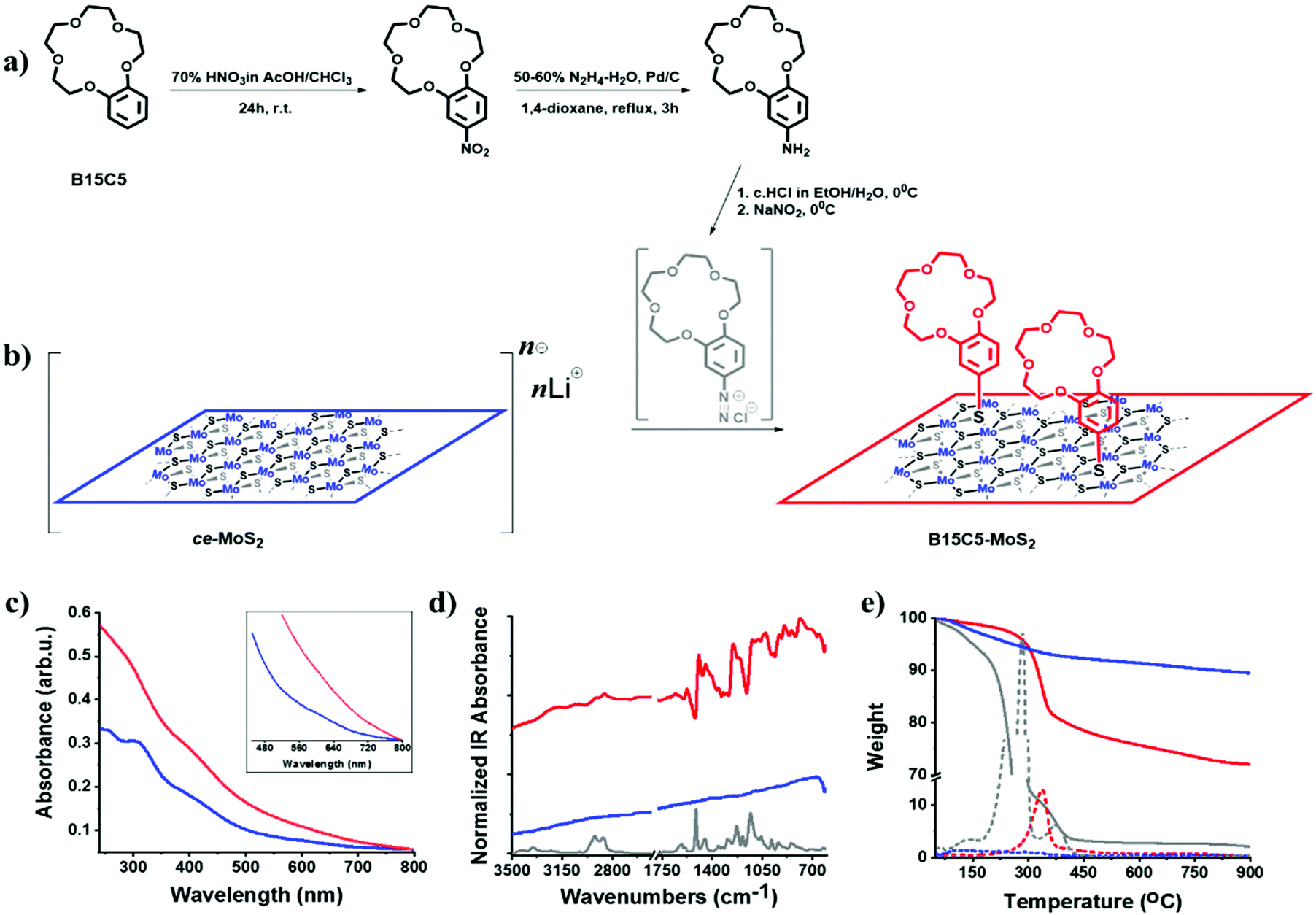 | ||
| Fig. 1 (a) Synthetic route towards 4′-aminobenzo-15-crown-5. (b) Schematic illustration of the ce-MoS2 functionalization route towards B15C5-MoS2via in situ generated diazonium salts. (c) UV-Vis spectra of ce-MoS2 (blue) and B15C5-MoS2 (red), obtained in deionized water. (d) Normalized FT-IR (presented as absorbance) spectra for B15C5 crown ether (grey), ce-MoS2 (blue) and B15C5-MoS2 (red). (e) TGA curves recorded for B15C5 (grey), ce-MoS2 (blue) and B15C5-MoS2, obtained under a nitrogen atmosphere. With dashed lines are presented the corresponding curves of the 1st derivative of weight versus temperature. | ||
In our case, the in situ formation of the B15C5 crown ether-based aryl diazonium salt, from the parent 4′-aminobenzo-15-crown-536,41 (Fig. 1a and b, and ESI, Fig. S3 and S4†), was performed both with excess of HCl and stoichiometric HCl (2 eq.) amounts. The B15C5-functionalized ce-MoS2, derived by the two approaches, was first studied by Fourier-transform infrared spectroscopy (FT-IR). The functionalized MoS2 nanosheets were thoroughly purified by consecutive sonication/centrifugation cycles to ensure the complete removal of the excess of the diazonium salt and any trapped or physisorbed traces from the reaction (see experimental details in the ESI†). The purification process was monitored by examining the FT-IR spectra of each supernatant and continued until no organic matter was present in the dried supernatant phase. Accordingly, the purified B15C5-MoS2 displayed FT-IR profiles emerging exclusively from the vibrations of the MoS2 lattice and the covalently grafted crown ether moiety. Interestingly, the two different approaches resulted in different signal intensities of the vibrations attributed to the covalently grafted B15C5 within B15C5-MoS2 (ESI, Fig. S5a†), while thermogravimetric analysis (TGA) also demonstrated different loading ratios (ESI, Fig. S5b†). In more detail, for the reaction with excess HCl, upon the dropwise addition of the in situ generated diazonium salt in the suspension of the ce-MoS2 nanosheets, aggregation and precipitation of the material within the first few drops occurred, while for the case of adding stoichiometric HCl the ce-MoS2 suspension remained stable during the course of the reaction. The characteristic IR vibration bands of the attached B15C5 species were found to be more intense (ESI, Fig. S5a†), and the loading increased from 17% to 25% w/w, when stoichiometric amounts of HCl were used for the preparation of the diazonium salt (ESI, Fig. S5b†). For the subsequent characterization and ion-binding assays, we discuss the B15C5-MoS2 material derived by using stoichiometric amounts of HCl for the in situ formation of the diazonium salt and the subsequent basal plane functionalization of ce-MoS2.
Insights into the stabilization of the 1T-phase during functionalization were obtained from Raman spectroscopy, using off-resonance (514 nm) and on-resonance (633 nm) excitation, with respect to the energy of the A exciton.42 The laser power was adjusted to 0.3 mW cm−2, and short exposure time (10 s) was used to avoid sample overheating and guarantee the stability of the samples during spectral acquisition.43 The J1, J2, J3 peaks located at 151, 221 and 329 cm−1, respectively, are the signature peaks arising from the 1T octahedral phase of MoS2 and can be detected under both excitation conditions (ESI, Fig. S6†). In more detail, these modes are of high intensity and well resolved for exfoliated ce-MoS2 under 514 nm excitation, while still remaining observable in B15C5-MoS2 (Fig. 2a), indicating the stabilization of the octahedral phase of MoS2via functionalization,17,44 in line with the aforementioned discussion on the UV-Vis spectroscopy findings. The co-existence of octahedral and trigonal prismatic coordination of Mo atoms, within ce-MoS2, is validated by the presence of the E12g mode (∼380 cm−1), usually observed in 2H-MoS2, since the 380 cm−1 phonon mode in octahedral coordination of Mo atoms is Raman inactive.13 The disorder induced across the quasi-2D crystals due to the chemical exfoliation and the phase transition from 2H-to-1T phase is also depicted by the broadening of the full-width-half-maximum (FWHM) of the A1g mode at 514 nm excitation. For the bulk and exfoliated 2H-MoS2,45 the FWHM values are 3.6 and 4.6 cm−1, respectively, whereas for ce-MoS2 and functionalized B15C5-MoS2 the registered value is 9.3 cm−1. Furthermore, from the frequency difference of A1g–E12g we calculated a value of 26 cm−1 for bulk 2H-MoS2, 22 cm−1 for ce-MoS2 and 21 cm−1 for B15C5-MoS2. These values represent a decrement in the layer thickness of the studied samples, and they are close to the value of 19 cm−1 of monolayer MoS2.46 Notably, the value of 21 cm−1 calculated for B15C5-MoS2 demonstrates that the basal plane functionalization protects MoS2 from restacking and further supports the successful incorporation of the B15C5 crown ether on the quasi-2D crystal lattice. Moving to the on-resonance spectra (633 nm), we clearly observe the J phonon modes for ce-MoS2, while for B15C5-MoS2 J2 is the most intense with J1 and J3 being almost indiscernible (Fig. 2b). Under resonance excitation, the intensity of the 2LA mode is strongly enhanced and is highly energy-dispersive.42,43,47 In a previous report, it was proposed that the intensity ratio of A1g (404 cm−1) to 2LA (∼450 cm−1) may assist as an evaluation tool for the basal plane functionalization of chemically exfoliated MoS2.18 More specifically, the A1g/2LA intensity ratio appeared to be increased as a result of MoS2 functionalization. Recently, the intensity ratio of 2LA/A1g was systematically investigated as a potential spectroscopic tool for monitoring the degree of sulfur vacancies on the basal plane of chemically exfoliated MoS2 during lattice healing with the aid of thiols.48 The 2LA/A1g ratio was found to increase as long as sulfur vacancies were occupied by thiols. Actually, from the recorded spectra shown in Fig. 2b we observe a slightly smaller A1g/2LA ratio for B15C5-MoS2 as compared to ce-MoS2.
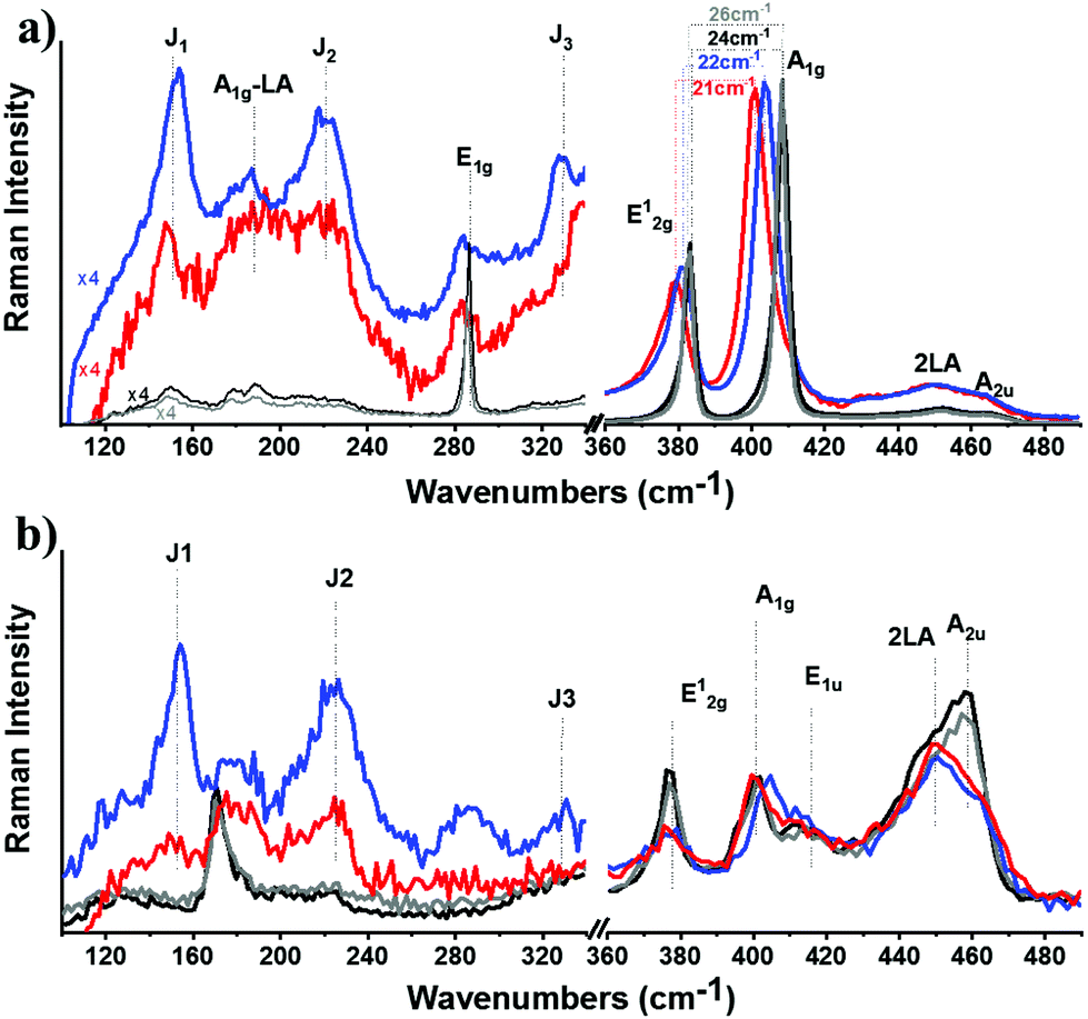 | ||
| Fig. 2 Raman spectra recorded for ce-MoS2 (blue) and B15C5-MoS2 (red) at (a) off-resonance (514 nm, 0.3 mW cm−2) and (b) on-resonance (633 nm, 0.3 mW cm−2) excitation. The spectra of bulk MoS2 (grey) and exfoliated 2H-MoS2 (black) are also presented for comparison. All spectra obtained under ambient conditions and normalized to the intensity of the A1g mode. | ||
To shed more light on the impact of chemical functionalization on the lattice disorder, instead of using the mean spectrum of the collected point-spectra, we performed spatial Raman mapping in order to probe the A1g/2LA ratio in a 20 μm × 20 μm area of the prepared materials, in order to probe the uniformity of the samples and the deviation of the intensity of the Raman modes of interest. Raman maps were constructed by acquiring and collecting 196 point-spectra for ce-MoS2 (ESI, Fig. S7a†) and B15C5-MoS2 (ESI, Fig. S7b†). The average A1g/2LA ratio for B15C5-MoS2, ca. 0.90, is around 10% lower (Fig. 3a) than that for ce-MoS2, ca. 0.98, (Fig. 3b), proving the enhancement of the local strain due to the chemical functionalization and induced symmetry disorder. Furthermore, we plotted the A1g/E12g intensity ratio for the two materials in order to qualitatively evaluate the stability of the 1T symmetry, as long as the E12g was Raman inactive for the octahedrally coordinated MoS2 and A1g was active in both polytypes.13 The A1g/E12g intensity ratio decreased by 4%, from 1.23 for ce-MoS2 to 1.19 for B15C5-MoS2, indicating partial structural transformation to 2H symmetry and evolution of the E12g mode (Fig. 3c and d). Along the same lines, the A1g/J2 (Fig. 3e and f) and E12g/J2 (Fig. 3g and h) intensity ratios were found to increase as a result of the functionalization. Collectively, UV-Vis and Raman spectroscopy showed that upon functionalization the metastable octahedral symmetry of Mo atoms within B15C5-MoS2 is significantly retained.
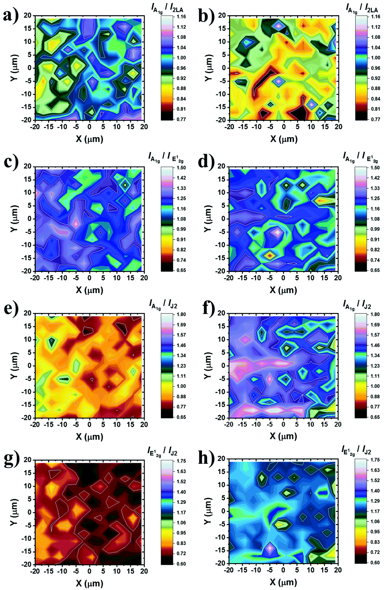 | ||
| Fig. 3 Raman intensity ratio maps from a 20 μm × 20 μm area (3 nm step, 196 points per spectra) of ce-MoS2 and B15C5-MoS2. (a, b) Plots of A1g/2LA for ce-MoS2 and B15C5-MoS2, respectively. (c, d) Plots of A1g/E12g for ce-MoS2 and B15C5-MoS2, respectively. (e, f) Plots of A1g/J2 for ce-MoS2 and B15C5-MoS2, respectively. (g, h) Plots of E12g/J2 for ce-MoS2 and B15C5-MoS2, respectively. All spectra recorded under on-resonance excitation (633 nm, 0.3 mW cm−2) under ambient conditions. A projection of each map is also given at the bottom for clarity. The spectra acquired for constructing the maps are presented in the ESI, Fig. S7.† | ||
The morphology of B15C5-MoS2 was analyzed by atomic force microscopy (AFM) and high-resolution transmission electron microscopy (HR-TEM). Free-of-aggregation B15C5-MoS2 was obtained by drop casting of aqueous diluted B15C5-MoS2 over a h-BN/SiO2 substrate. Based on AFM imaging, B15C5-MoS2 shows a nanoribbon-like structure, typically with dimensions of 10 nm × 80 nm and an average height of 4 nm (Fig. 4a). Fig. 4b shows a higher magnification low-height single B15C5-MoS2 nanoribbon. This B15C5-MoS2 has a height of 1.3 nm (Fig. 4c), which topically enhances by 1–2 nm by the presence of single B15C5 species and/or due to interactions with the h-BN substrate that cause folds and twists of the MoS2. Additional morphological insight on B15C5-MoS2 was possible by HR-TEM. Specifically, MoS2 in B15C5-MoS2 shows random distribution of the edges with low defects on the basal plane (Fig. 4d). Due to the presence of B15C5 on the surface of MoS2, dark areas are registered, making it difficult to accurately interpret the atomic structure of B15C5-MoS2. On the other hand, fast Fourier transform (FFT) analysis of the TEM image (Fig. 4e) shows a hexagonal pattern, proving the presence of a highly crystalline single layer of MoS2. Finally, electron dispersive X-ray (EDX) spectroscopy (Fig. 4f) reveals relatively high amounts of C and O derived from the added B15C5 as well as Mo and S from MoS2 at 0.278, 0.521, 2.32 and 2.46 keV, respectively, ensuring the covalent functionalization and formation of B15C5-MoS2. On the other hand, ce-MoS2 tends to form van der Waals aggregates, and extended regions of monolayers or bilayers were completely absent as revealed by AFM imaging. The average AFM height of ce-MoS2 was double that of B15C5-MoS2, ca. 8–9 nm (ESI, Fig. S8a and b†). Further TEM analysis of ce-MoS2 shows crystalline areas free of holes (ESI, Fig. S8c†). Apparently, the current covalent functionalization of ce-MoS2 with B15C5 not only results in further delamination of MoS2 but also blocks aggregation of the exfoliated material.
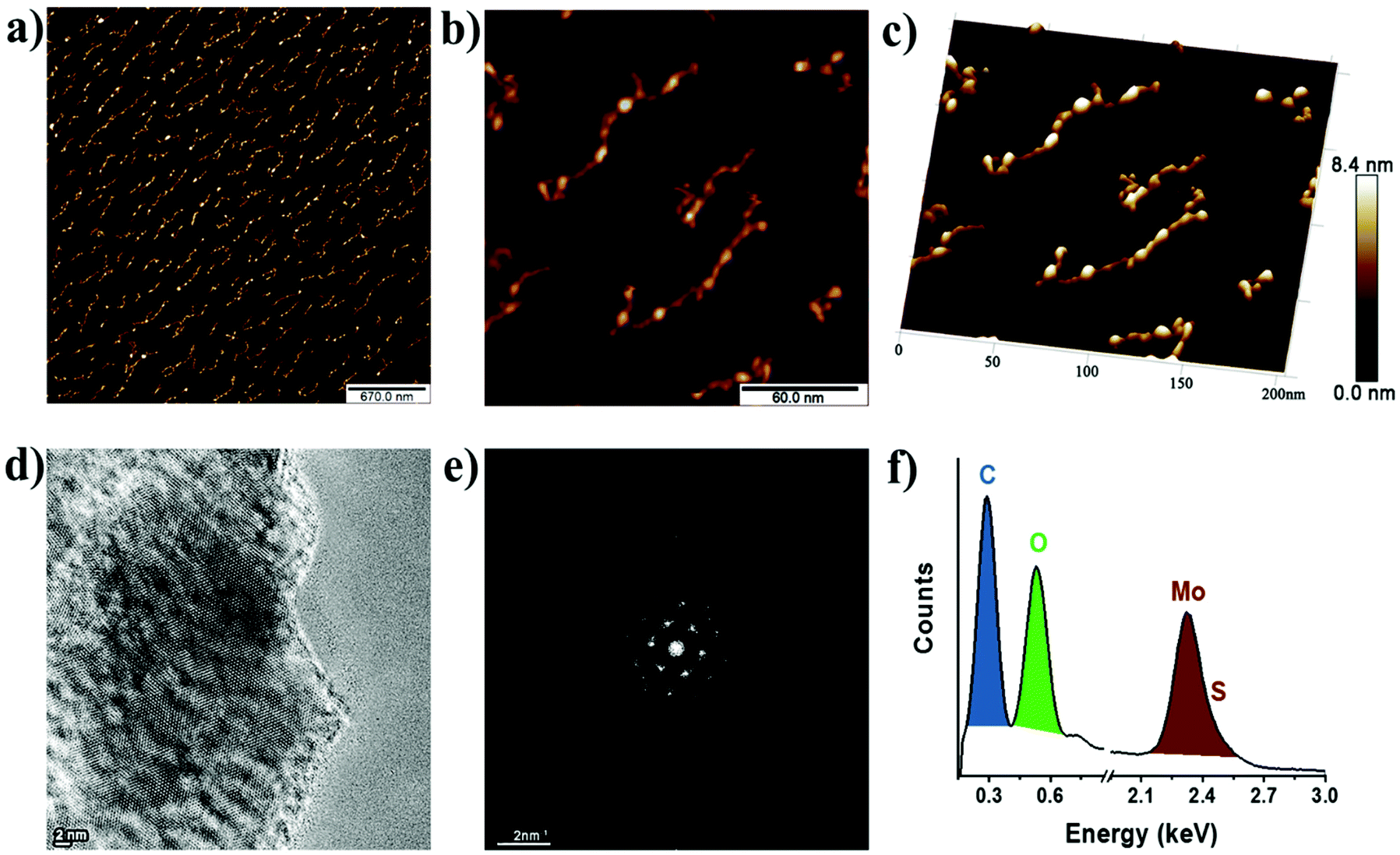 | ||
| Fig. 4 AFM image of B15C5-MoS2 at (a) low and (b) high magnification. (c) 3D-AFM image of B15C5-MoS2 at high magnification. The height scale bar is common in (a–c). (d) TEM micrograph of B15C5-MoS2 taken under focus conditions to enhance contrast from MoS2. (e) FFT-TEM, and (f) EDX from the same region of B15C5-MoS2. | ||
As comprehensively presented by the UV-Vis and Raman spectroscopy studies, the structural and electronic characteristics of B15C5-MoS2 resemble those of the octahedral symmetry MoS2, while owing a significant amount of a covalently grafted ion-recognition motif. In this context, B15C5-MoS2 was evaluated as an ion-responsive electrode for monitoring the levels of sodium in aqueous media and artificial sweat. Initially, B15C5-MoS2 was deposited on a glassy carbon disk electrode (GC), in the form of a thin film, for capacitance studies (ESI, Fig. S9a, c and e†). Cyclic voltammetry (CV) studies were performed in nitrogen-saturated aqueous 0.5 M H2SO4 in the non-faradaic region (−0.2 to +0.2 V vs. Ag/AgCl), while GC/ce-MoS2 and GC/B15C5 electrodes were also tested for reference. Chemically exfoliated MoS2 has a high surface area generating high capacitance values.49 Actually, the GC/ce-MoS2 electrode displays a value of 2.77 μF cm−2, which is two orders of magnitude higher than that of bare GC, i.e. 0.025 μF cm−2, and 47-times higher than that of GC/B15C5-MoS2, i.e. 0.059 μF cm−2, (ESI, Fig. S9b, d and f†). The decreased value registered for GC/B15C5-MoS2 is related to the presence of covalently grafted B15C5 on the basal plane of MoS2, which blocks the interactions of the electrolyte and the conductive lattice. The latter was further probed by CV runs in the presence of the redox probe [Fe(CN)6]4−/[Fe(CN)6]3− (ESI, Fig. S10a†). For GC/B15C5-MoS2, the recorded signal is suppressed, as compared to the reference GC/ce-MoS2 electrode, since the negatively charged iron complex experiences difficultly in approaching the also negatively-charged oxygen-containing crown ether. However, the signal is not totally suppressed, since the counter potassium cations of the [Fe(CN)6]4−/[Fe(CN)6]3− probe are possibly weakly coordinated to the macrocyclic ether, mediating the electronic communication with the surface of the MoS2 lattice. Eventually, CV runs were performed in the presence of sodium cations, which strongly coordinate to the B15C5 domain of the GC/B15C5-MoS2 electrode. In the presence of Na+ the recorded signal is enhanced, indicating the attraction of the [Fe(CN)6]4−/[Fe(CN)6]3− probe to the electrode surface (ESI, Fig. S10c†), in contrast to the non-modified ce-MoS2 electrode, in which the impact of sodium is negligible since no coordination sites are present (ESI, Fig. S10b†). Coordination of sodium to the crown ether decreases the negative charge around the macrocyclic ether and allows for enhanced electrostatic attractive interactions between the coordinated sodium and the redox probe. Moreover, the intensity of the signal is further increased in the second run, suggesting that a short incubation time is required to reach equilibrium.
Given the electrochemical data for the GC/B15C5-MoS2 electrode in the presence of sodium ions, we moved forward and studied the potentiometric response of the nanosheets in the range of 0.1–100 mM of sodium cations in aqueous media with the aid of an electrochemical cell equipped with an Ag/AgCl reference electrode. Recent advances in the fabrication of potentiometric wearable sensors offer the advantage of utilizing such reference electrode systems as ink pseudo-reference electrodes for monitoring the open circuit potential (OCP) between the layer of the ion-responsive electrode and the reference electrode.50 Initially, we used distilled water as a medium for the electrochemical cell, with pH value ca. 5.8 within the pH range of human sweat, i.e. 4.5–7.0; then sodium chloride was gradually introduced, and the OCP response of the GC/B15C5-MoS2 electrode was recorded (Fig. 5a). The GC/ce-MoS2 electrode was also assessed as a reference system, in which the ion-selective B15C5 crown ether was absent. Upon incremental addition of NaCl, the OCP increases as a result of the increased ionic strength of the aqueous medium, and the OCP versus log[Na+] plot demonstrates a linear response (R2 = 0.990) of the GC/B15C5-MoS2 electrode in the region of CNaCl 10−4–10−1 M (Fig. 5b). Ideally, assuming that only the analyte is taken up on the electrode, an ion-selective electrode (ISE) exhibits a Nernstian behavior when the slope of the OCP versus log[Na+] plot gives a value of 59 mV dec−1 of concentration change, while for sodium cations the charge of the analyte (n) equals +1. From the slopes of the OCP versus log[Na+] plots in aqueous solution for the GC/B15C5-MoS2 electrode we calculate a value of 22.8 mV dec−1 of concentration change with n = 2.58 and excellent linearity (R2 = 0.999). In contrast, the reference GC/ce-MoS2 electrode displays a fairly linear response, however, with much lower sensitivity (R2 = 0.990, 8.2 mV dec−1, n = 7.21), while for the reference GC/B15C5 electrode the calculated values (R2 = 0.990, 15.2 mV dec−1, n = 3.88) are slightly better than those for GC/ce-MoS2. To further probe the performance of the GC/B15C5-MoS2 electrode, we performed selectivity tests by injecting competitive analytes, which are present in human sweat, albeit at much lower concentrations than that of sodium. Accordingly, we recorded the potentiometric response of the GC/B15C5-MoS2 electrode by subsequent addition of 10 mM Na+, 10 mM K+, 10 mM Li+, 10 mM Mg2+ and 10 mM Zn2+ (Fig. 5c). As expected, the high selectivity of the B15C5 crown ether, within the GC/B15C5-MoS2 electrode, towards Na+ resulted in a higher potentiometric response than K+, while for the rest of the ions the response was negligible. Considering that Na+, alongside with Cl−, is the dominant species in human sweat and that the usual concentration range of K+ is at least an order of magnitude lower than Na+ while those of other common metal ions (Li+, Mg2+, Zn2+etc.) are on the micromolar and sub-micromolar scales,51 the GC/B15C5-MoS2 electrode could be an ideal future candidate for monitoring applications. Therefore, we further examined the sodium-response of B15C5-MoS2 in an aqueous matrix of artificial sweat (6 mM KCl, 0.08 mM MgCl2, 0.18 mM pyruvic acid, 0.17 mM glucose, 5 mM NH4Cl and 10 mM urea).52 Notably, the GC/B15C5-MoS2 electrode exhibits a linear behavior (R2 = 0.999) upon incremental addition of sodium ions, whereas the reference GC/ce-MoS2 and GC/B15C5 electrodes display lower linearity (R2 = 0.980 and 0.969, respectively) (Fig. 5d and e). The potentiometric response of the GC/B15C5-MoS2 electrode in the artificial sweat matrix is rather improved, approaching a quasi-Nernstian behavior, with registered values of 35.21 mV dec−1 of concentration change and n = 1.67. Evidently, the presence of agonist cation analytes (K+, Mg2+, NH4+) in the artificial sweat matrix does not block the selectivity of the covalently grafted B15C5 macrocyclic ether for sodium cations. These findings support the beneficial role of the covalently incorporated B15C5 onto MoS2 as an ionophore for sodium ions and the potential use of GC/B15C5-MoS2 as an ion-selective electrode. The presence of B15C5 macrocycles within B15C5-MoS2 assists the attraction of sodium ions close to the surface of the electrode. Moreover, we conclude that post-functionalization engineering of the surface of the GC/B15C5-MoS2 electrode further assists in improving the response and stability of such hybrid MoS2-based ion-sensing electrodes.
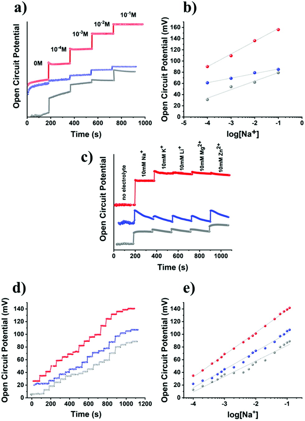 | ||
| Fig. 5 (a) Open circuit potential (OCP) response with respect to the concentration of Na+ (0, 10−4, 10−3, 10−2 and 10−1 M), and (b) the corresponding OCP versus log[Na+] plots for GC/B15C5-MoS2 (red), GC/ce-MoS2 (blue) and GC/B15C5 (grey) electrodes, in an aqueous environment. (c) OCP response for the GC/B15C5-MoS2 (red), GC/ce-MoS2 (blue) and GC/B15C5 (grey) electrodes in the absence of electrolyte and in the presence of subsequently added 10 mM Na+, 10 mM K+, 10 mM Li+, 10 mM Mg2+ and 10 mM Zn2+ in an aqueous environment. (d) OCP response for the GC/B15C5-MoS2 (red), GC/ce-MoS2 (blue) and GC/B15C5 (grey) electrodes at 0.1, 0.2, 0.4, 0.6, 0.8, 1.0, 2.0, 4.0, 6.0, 8.0, 10.0, 20.0, 40.0, 60.0, 80.0, 100.0 and 120.0 mM Na+ within an artificial sweat solution matrix, and (e) the corresponding OCP versus log[Na+] plots. | ||
Conclusions
In this work, we took advantage of the facile diazonium chemistry for the basal plane functionalization of ce-MoS2 nanosheets with benzo-15-crown-5 ether (B15C5). The newly synthesized B15C5-MoS2 was studied by FT-IR and TGA, and the successful chemical incorporation of the macrocyclic polyether was validated. UV-Vis and Raman spectroscopy revealed the stabilization of the octahedral (1T) symmetry within the B15C5-MoS2 nanosheets in equilibrium to the trigonal prismatic (2H). The registered ratio of A1g/2LA intensity from spatial Raman mapping showed that the incorporation of B15C5 on the basal plane of MoS2 induces a symmetry distortion, however, it prevents the nanosheets against restacking and stabilizes the metastable 1T phase of the exfoliated quasi-2D nanocrystals. Cyclic voltammetry assays further supported the surface functionalization of MoS2, since the calculated double layer capacitance value was almost 50-times lower than that of non-modified ce-MoS2, suggesting that the surface of B15C5-MoS2 was blocked by the incorporated B15C5 units. Finally, B15C5-MoS2 electrodes were constructed, and we investigated the response in the presence of sodium ions. We, initially, witnessed improved electrochemical signal of the [Fe(CN)6]4−/[Fe(CN)6]3− redox probe in the presence of sodium ions, as a result of the coordination of sodium ions to the crown ether within B15C5-MoS2 enabling the electronic communication between the negatively charged redox complex and the conductive nanosheets. Then, B15C5-MoS2 was evaluated as a responsive electrode for the potentiometric monitoring of sodium ions in aqueous media and artificial sweat matrix. As compared to the non-functionalized ce-MoS2 nanosheets, the B15C5-MoS2 electrodes exhibited a linear increase of the recorded open circuit potential upon incremental addition of sodium ions, while displaying a quasi-Nernstian behavior. The crown-ether functionalized MoS2 nanosheets showed potential for sensing sodium ions in liquid samples. It is anticipated that post-functionalization engineering of their surface may further improve their electrochemical response, opening avenues for utilization as ion-selective electrodes in wearable sensors.Chemicals
MoS2 powder (particle size ∼6 μm, max. 40 μm), benzo-15-crown-5 (98%), K4Fe(CN)6, tetrabutylammonium bromide, nitric acid 70%, hydrazine hydrate 50–60%, Pd/C, n-BuLi (2.5 M in hexanes), NaCl, KCl, MgCl2, pyruvic acid, glucose, NH4Cl, urea were commercially available and used as received.Instrumentation
Ultrasonication was performed with the aid of a Bandelin Sonoplus GM3200 system equipped with a VS 70 T extended probe at 50% power (75 W, 20 kHz). High-resolution transmission electron microscopy (HR-TEM) was performed on a JEOL JEM-2100F system equipped with Energy Dispersive X-Ray (EDX) spectroscopy, working at 80 keV. TEM images were processed by Gatan DigitalMigrograph and ImageJ. Atomic force microscopy (AFM) observations were performed by using the Veeco AFM system (Dimension 3100SPM, Nanoscope IV) operating at a scanning rate of 1 Hz. The tip used in AFM was RESPA-300, employing the contact mode with a strength of 0.3 V. Sample preparation was performed by dissolving 0.5 mg of B15C5-MoS2 in 1 mL of water and sonicating for 1 h. Then, h-BN/SiO2 was submersed in the aqueous solution. After several hours, B15C5-MoS2 attached onto the h-BN/SiO2 substrate, and it was dried by employing a spin coater MS-A100 at 6000 rpm. Steady-state UV-Vis absorption spectra were recorded on a Perkin–Elmer (Lambda 19) UV–vis–NIR spectrophotometer. FT IR spectra were recorded on a Bruker Equinox 55 FTIR spectrometer equipped with a Pike Miracle Ge ATR accessory. Micro-Raman scattering measurements were performed at room temperature in the backscattering geometry using a RENISHAW inVia Raman microscope equipped with a CCD camera and a Leica microscope. A 2400 lines per mm grating (for 514 nm) and 2400 lines per mm grating (for 633 nm) were used, providing a spectral resolution of ±1 cm−1. As an excitation source, Ar (514 nm) and He/Ne lasers (633 nm) were used. Measurements were taken with 10 seconds of exposure times and laser power of ∼0.3 mW cm−2 to prevent overheating and damage of the basal plane. The laser spot was focused on the sample surface using a long working distance 50× (L50) objective. Raman spectra were collected on numerous spots on the sample and recorded with a Peltier cooled CCD camera. The data were collected and analyzed with Renishaw Wire and Origin software. Electrochemical measurements were carried out in a standard three-compartment electrochemical cell using a rotating disk electrode (RDE) setup from Metrohm Autolab connected to an AUTOLAB PGSTAT128N potentiostat/galvanostat instrument connected to a personal computer running the Nova 2.1 software. As the counter electrode, a platinum foil was used, and as the reference an Ag/AgCl (aqueous 3.0 M KCl electrolyte) electrode was placed into a Luggin capillary. The working electrode was a glassy carbon (GC) disk (geometric surface area, 0.071 cm2) without using rotation. The working electrode was cleaned before each experiment through polishing with a cloth and 6, 3 and 1 μm diamond pastes. The GC/B15C5-MoS2 and GC/ce-MoS2 electrodes were prepared by deposition of the materials in the form of thin films on top of the GC surface.Preparation of ce-MoS2
[Extreme care must be taken when working with n-BuLi, since it reacts violently with humidity and water and is pyrophoric. A well-ventilated hood is also required.] Initially, 750 mg (4.68 mmol) of bulk 2H-MoS2 was placed in a furnace at 300 °C for 24 h. Then, the dried powder was placed in a 10 mL flask with a magnetic stir bar and cooled to room temperature under a nitrogen atmosphere. Under a nitrogen atmosphere, 7.5 mL (18.75 mmol) of 2.5 M n-BuLi was introduced, and the mixture was stirred vigorously for 48 h under nitrogen. After this period, the black suspension was left to settle, the intercalated solid Lix–MoS2 was precipitated, and the supernatant n-BuLi solution was pipetted-off under nitrogen. Then 15 mL of dry hexane was introduced under a nitrogen atmosphere, and the mixture was vigorously stirred for 10 minutes. Then, the black suspension was left to settle, the intercalated solid Lix–MoS2 was precipitated, and the supernatant containing the excess n-BuLi was pipetted-off under nitrogen. This step was repeated two more times to ensure the removal of excess n-BuLi from the reaction mixture. The residual black slurry of Lix–MoS2 was opened in the air and rapidly immersed in a 1 L flask filled with 750 mL of cold distilled water. Water reacted rapidly with the Lix–MoS2 evolving gas. The immersed flask and the stir bar were removed, and the mixture (C = 1 mg mL−1) was ultra-sonicated for 3 h (pulse ON:3 s–OFF:3 s) keeping the temperature below 30 °C with the aid of an ice bath. Finally, the suspension was left to settle overnight, and the top 2/3 was collected and stored in a sealed flask in the dark and below 30 °C. The concentration of the ce-MoS2 suspension was calculated as follows: 3 mL of the suspension was filtered over a pre-weight PTFE membrane filter under vacuum and washed with distilled water and ethanol; the filter cake was dried under vacuum and weighted. Accordingly, the concentration of the suspension was calculated to be as high as 0.87 mg mL−1. The suspension remained stable without any precipitation for several weeks. The stability of the 1T phase and the transformation to the 2H phase were monitored periodically with UV-Vis spectroscopy, and no well-resolved peaks were evident for at least 40 days under storage conditions (Fig. S1†).
Synthesis of 4′-aminobenzo-15-crown-5 (B15C5-NH2)36
Step 1: To a mixture of benzo-15-crown-5 (1.5 g, 5.6 mmol), acetic acid (18 mL) and chloroform (20 mL), nitric acid (5 mL, 70%) was added dropwise over 30 minutes. The mixture was left to stir at room temperature for 24 h, followed by neutralization with saturated aqueous NaHCO3. The organic layer was separated, and the aqueous layer was extracted with CHC13. The combined organic layers were dried (Na2SO4), filtered and evaporated to dryness. Recrystallization of the resulting yellow residue in ethanol then gave 4′-nitrobenzo-15-crown-5 as a white solid, after being filtered, washed with cold ethanol and dried under vacuum (1.3 g, 75%). 1H NMR (300 MHz, CDCl3): δ 3.76 (m, 8H), 3.93 (m, 4H), 4.20 (m, 4H), 6.86 (d, J = 9 Hz, 1H), 7.71 (s, 1H), 7.88 (d, J = 9 Hz, 1H) ppm.Step 2: A mixture of 4′-nitrobenzo-15-crown-5 (1.1 g, 3.51 mmol) and 10% Pd/C (0.1 g) in 1,4-dioxane (20 mL) was heated to reflux. Next, hydrazine hydrate (10 mL, 50–60%) was added dropwise, and the resulting solution was refluxed for 3 h. After cooling to room temperature, the solution was passed through Celite and concentrated to dryness to give 4′-aminobenzo-15-crown-5 (B15C5-NH2) as a light brown viscous solid (0.9 g, 91%). The product was used without further purification. 1H NMR (300 MHz, CDCl3): δ 3.75 (m, 8H), 3.89 (m, 4H), 4.06 (m, 4H), 6.21 (d, J = 6 Hz, 1H), 6.28 (s, 1H), 6.73 (d, J = 6 Hz, 1H) ppm.
Preparation of the in situ formed B15C5-diazonium salt
In a round bottom flask, 0.5 mmol (141 mg) of B15C5-NH2 were dissolved in 2 mL of EtOH, followed by addition of 3 mL of distilled H2O and 1.2 mmol (100 μL) of concentrated HCl. The slight-yellow transparent solution was cooled under stirring in an ice-bath (solution A). Then NaNO2 (60 mg, 0.87 mmol) was dissolved in 1 mL of distilled H2O and cooled in an ice-bath (solution B). The cold solution B was added to solution A under stirring in an ice-bath. The final mixture was left under stirring in the cold bath for 30 min, and the color turned to deep orange indicating the diazotization reaction.Preparation of the covalently functionalized B15C5-MoS2
In a round bottom flask, 23 mL (∼20 mg) of an aqueous ce-MoS2 suspension were added and cooled in an ice-bath under nitrogen atmosphere and stirring. The cold solution containing the in situ prepared diazonium salt was added dropwise, and the mixture was allowed to reach r.t. overnight. During the addition of the diazonium salt, bubbles evolved due to the loss of nitrogen. The mixture was left at r.t. under stirring for another 24 h to ensure completion of the reaction. Then, the mixture was centrifuged and washed thoroughly with 1× distilled H2O, 1× MeOH and acetone (consecutive sonication/centrifugation cycles) until the supernatant was colorless, indicating the removal of the non-reacted diazonium salt, and no organic residuals were present (monitored by FT-IR). Finally, the black solid was dried in vacuum at r.t. The dried black powder, abbreviated as B15C5-MoS2, was used for further characterization and studies.Preparation of thin-film GC/B15C5-MoS2. GC/ce-MoS2 and GC/B15C5 and formation of electrodes
1 mg of B15C5-MoS2 was dispersed in distilled water with the aid of mild ultrasonication, furnishing a dispersion with C = 1 mg mL−1. 20 μL of the suspension was deposited on the surface of the polished GC electrode and dried at r.t. under vacuum. In an analogous manner, 10 μL of the ce-MoS2 aqueous suspension (C = 0.87 mg mL−1) was deposited on the surface of the polished GC electrode and dried at r.t. under vacuum. For the preparation of the GC/B15C5 electrode, 10 mg of B15C5 was dissolved in an isopropanol solution containing Nafion, and a 20 μL aliquot of the solution was drop-casted on the surface of the polished GC electrode and dried at r.t. under vacuum.Conflicts of interest
There are no conflicts to declare.Acknowledgements
This research is co-financed by Greece and the European Union (European Social Fund – ESF) through the Operational Programme “Human Resources Development, Education and Lifelong Learning 2014–2020” in the context of the project “Chemically modified MoS2 with organic recognition motifs as electrochemical sensors for the selective detection of ions and (bio)molecules” (MIS 5048201). This work is also supported by Japan Society for the Promotion of Science (JSPS) postdoctoral fellowship grant agreement no P19368.References
- G. H. Han, D. L. Duong, D. H. Keum, S. J. Yun and Y. H. Lee, Chem. Rev., 2018, 118, 6297–6336 CrossRef CAS PubMed.
- S. Manzeli, D. Ovchinnikov, D. Pasquier, O. V. Yazyev and A. Kis, Nat. Rev. Mater., 2017, 2, 17033 CrossRef CAS.
- P. Joensen, R. F. Frindt and S. R. Morrison, Mater. Res. Bull., 1986, 21, 457–461 CrossRef CAS.
- M. A. Py and R. R. Haering, Can. J. Phys., 1983, 61, 76–84 CrossRef CAS.
- K. Chrissafis, M. Zamani, K. Kambas, J. Stoemenos, N. A. Economou, I. Samaras and C. Julien, Mater. Sci. Eng., B, 1989, 3, 145–151 CrossRef.
- X. Cai, Y. Luo, B. Liu and H.-M. Cheng, Chem. Soc. Rev., 2018, 47, 6224–6266 RSC.
- R. B. Somoano and J. A. Woollam, in Intercalated Layered Materials, ed. F. Lévy, D. Reidel Publishing Company, Dordrecht (NL), 1979, pp. 307–371, DOI:10.1007/978-94-009-9415-7.
- M. S. Stark, K. L. Kuntz, S. J. Martens and S. C. Warren, Adv. Mater., 2019, 31, e1808213 CrossRef PubMed.
- Y. Jung, Y. Zhou and J. J. Cha, Inorg. Chem. Front., 2016, 3, 452–463 RSC.
- J. Wan, S. D. Lacey, J. Dai, W. Bao, M. S. Fuhrer and L. Hu, Chem. Soc. Rev., 2016, 45, 6742–6765 RSC.
- J. Shi, M. Hong, Z. Zhang, Q. Ji and Y. Zhang, Coord. Chem. Rev., 2018, 376, 1–19 CrossRef CAS.
- S. Jiménez Sandoval, D. Yang, R. F. Frindt and J. C. Irwin, Phys. Rev. B: Condens. Matter Mater. Phys., 1991, 44, 3955–3962 CrossRef PubMed.
- D. Yang, S. J. Sandoval, W. M. R. Divigalpitiya, J. C. Irwin and R. F. Frindt, Phys. Rev. B: Condens. Matter Mater. Phys., 1991, 43, 12053–12056 CrossRef CAS PubMed.
- G. Eda, H. Yamaguchi, D. Voiry, T. Fujita, M. Chen and M. Chhowalla, Nano Lett., 2011, 11, 5111–5116 CrossRef CAS PubMed.
- S. Bertolazzi, M. Gobbi, Y. Zhao, C. Backes and P. Samorì, Chem. Soc. Rev., 2018, 47, 6845–6888 RSC.
- A. Stergiou and N. Tagmatarchis, Chem. – Eur. J., 2018, 24, 18246–18257 CrossRef CAS PubMed.
- D. Voiry, A. Goswami, R. Kappera, C. D. C. C. E. Silva, D. Kaplan, T. Fujita, M. Chen, T. Asefa and M. Chhowalla, Nat. Chem., 2015, 7, 45–49 CrossRef CAS.
- K. C. Knirsch, N. C. Berner, H. C. Nerl, C. S. Cucinotta, Z. Gholamvand, N. McEvoy, Z. Wang, I. Abramovic, P. Vecera, M. Halik, S. Sanvito, G. S. Duesberg, V. Nicolosi, F. Hauke, A. Hirsch, J. N. Coleman and C. Backes, ACS Nano, 2015, 9, 6018–6030 CrossRef CAS.
- E. Er, H.-L. Hou, A. Criado, J. Langer, M. Möller, N. Erk, L. M. Liz-Marzán and M. Prato, Chem. Mater., 2019, 31, 5725–5734 CrossRef CAS.
- G. Matzeu, L. Florea and D. Diamond, Sens. Actuators, B, 2015, 211, 403–418 CrossRef CAS.
- T. Liu and Z. Liu, Adv. Healthcare Mater., 2018, 7, e1701158 CrossRef PubMed.
- J. H. Appel, D. O. Li, J. D. Podlevsky, A. Debnath, A. A. Green, Q. H. Wang and J. Chae, ACS Biomater. Sci. Eng., 2016, 2, 361–367 CrossRef CAS PubMed.
- A. M. Ribeiro, T. H. S. Flores-Sahagun and R. C. Paredes, J. Mater. Sci., 2015, 51, 2806–2816 CrossRef.
- D. McManus, S. Vranic, F. Withers, V. Sanchez-Romaguera, M. Macucci, H. Yang, R. Sorrentino, K. Parvez, S. K. Son, G. Iannaccone, K. Kostarelos, G. Fiori and C. Casiraghi, Nat. Nanotechnol., 2017, 12, 343–350 CrossRef CAS PubMed.
- C. J. Pedersen, J. Am. Chem. Soc., 1967, 89, 2495–2496 CrossRef CAS.
- C. J. Pedersen, J. Am. Chem. Soc., 1967, 89, 7017–7036 CrossRef CAS.
- J. S. Bradshaw and R. M. Izatt, Acc. Chem. Res., 1997, 30, 338–345 CrossRef CAS.
- J. W. Steed, Coord. Chem. Rev., 2001, 215, 171–221 CrossRef CAS.
- L. Moreira, B. M. Illescas and N. Martín, J. Org. Chem., 2017, 82, 3347–3358 CrossRef CAS PubMed.
- J. Guo, J. Lee, C. I. Contescu, N. C. Gallego, S. T. Pantelides, S. J. Pennycook, B. A. Moyer and M. F. Chisholm, Nat. Commun., 2014, 5, 5389 CrossRef CAS PubMed.
- R. Krishnakumar and R. S. Swathi, ACS Appl. Mater. Interfaces, 2017, 9, 999–1010 CrossRef CAS PubMed.
- A. Smolyanitsky, E. Paulechka and K. Kroenlein, ACS Nano, 2018, 12, 6677–6684 CrossRef CAS PubMed.
- K. R. Bang, D. Bahamon, L. F. Vega and E. S. Cho, Adv. Mater. Interfaces, 2020, 7, 1901876 CrossRef CAS.
- M. A. Santa Ana, N. Mirabal, E. Benavente, P. Gómez-Romero and G. González, Electrochim. Acta, 2007, 53, 1432–1438 CrossRef CAS.
- N. Lara and E. Ruiz-Hitzky, J. Braz. Chem. Soc., 1996, 7, 193–197 CrossRef CAS.
- R. Ungaro, B. El Haj and J. Smid, J. Am. Chem. Soc., 1976, 98, 5198–5202 CrossRef CAS.
- J. D. Owen and M. R. Truter, J. Chem. Soc., Dalton Trans., 1979, 1831–1835, 10.1039/DT9790001831.
- J. M. Maud, J. F. Stoddart, H. M. Colquhoun and D. J. Williams, Polyhedron, 1984, 3, 675–679 CrossRef CAS.
- Y. Inokuchi, O. V. Boyarkin, R. Kusaka, T. Haino, T. Ebata and T. R. Rizzo, J. Phys. Chem. A, 2012, 116, 4057–4068 CrossRef CAS PubMed.
- E. Benavente, M. A. Santa Ana, F. Mendizábal and G. González, Coord. Chem. Rev., 2002, 224, 87–109 CrossRef CAS.
- T. Liu, C. Bao, H. Wang, Y. Lin, H. Jia and L. Zhu, Chem. Commun., 2013, 49, 10311–10313 RSC.
- X. Zhang, X. F. Qiao, W. Shi, J. B. Wu, D. S. Jiang and P. H. Tan, Chem. Soc. Rev., 2015, 44, 2757–2785 RSC.
- B. C. Windom, W. G. Sawyer and D. W. Hahn, Tribol. Lett., 2011, 42, 301–310 CrossRef CAS.
- M. Calandra, Phys. Rev. B: Condens. Matter Mater. Phys., 2013, 88, 245428-6 CrossRef.
- Q. Qian, Z. Zhang and K. J. Chen, Langmuir, 2018, 34, 2882–2889 CrossRef CAS PubMed.
- C. Lee, H. Yan, L. E. Brus, T. F. Heinz, J. Hone and S. Ryu, ACS Nano, 2010, 4, 2695–2700 CrossRef CAS PubMed.
- B. Chakraborty, H. S. S. R. Matte, A. K. Sood and C. N. R. Rao, J. Raman Spectrosc., 2013, 44, 92–96 CrossRef CAS.
- X. Chen, P. Denninger, T. Stimpel-Lindner, E. Spiecker, G. S. Duesberg, C. Backes, K. C. Knirsch and A. Hirsch, Chem. – Eur. J., 2020, 26, 6535–6544 CrossRef CAS.
- J. Chen, W. R. Walker, L. Xu, O. Krysiak, Z. She and M. A. Pope, ACS Nano, 2020, 14, 5636–5648 CrossRef CAS.
- A. Cazalé, W. Sant, F. Ginot, J. C. Launay, G. Savourey, F. Revol-Cavalier, J. M. Lagarde, D. Heinry, J. Launay and P. Temple-Boyer, Sens. Actuators, B, 2016, 225, 1–9 CrossRef.
- J. R. Cohn and E. A. Emmett, Ann. Clin. Lab. Sci., 1978, 8, 270–275 CAS.
- T. Glennon, C. O'Quigley, M. McCaul, G. Matzeu, S. Beirne, G. G. Wallace, F. Stroiescu, N. O'Mahoney, P. White and D. Diamond, Electroanalysis, 2016, 28, 1283–1289 CrossRef CAS.
Footnotes |
| † Electronic supplementary information (ESI) available: NMR spectra for the synthesis of the organic compounds. Supplementary UV-Vis and Raman spectroscopy spectra for ce-MoS2 and B15C5-MoS2 materials. Supplementary FT-IR, TGA and electrochemistry characterization for ce-MoS2 and B15C5-MoS2 materials. See DOI: 10.1039/d1nr00404b |
| ‡ Equal contribution. |
| This journal is © The Royal Society of Chemistry 2021 |