 Open Access Article
Creative Commons Attribution 3.0 Unported Licence
Correction: Design and characterization of a plasmonic Doppler grating for azimuthal angle-resolved surface plasmon resonances
Kel-Meng
See
a,
Fan-Cheng
Lin
a and
Jer-Shing
Huang
 *abc
*abc
aDepartment of Chemistry, National Tsing Hua University, 101 Sec. 2, Kuang-Fu Road, Hsinchu 30013, Taiwan. E-mail: jer-shing.huang@leibniz-ipht.de
bLeibniz Institute of Photonic Technology, Albert-Einstein Str. 9, 07745 Jena, Germany
cResearch Center for Applied Sciences, 128 Sec. 2, Academia Road, Nankang, Taipei 11529, Taiwan
First published on 22nd December 2020
Abstract
Correction for ‘Design and characterization of a plasmonic Doppler grating for azimuthal angle-resolved surface plasmon resonances’ by Kel-Meng See et al., Nanoscale, 2017, 9, 10811–10819, DOI: 10.1039/C7NR01509G.
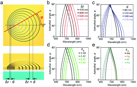
The authors regret that Fig. 1e of the original paper contained an error in the curves displayed for the silver, aluminium and palladium gratings. Specifically, a different value of the ‘index of the environment’ (1.65) was used in the calculation of these curves compared to that used for calculating the optical response of the gold grating (1.33). The correct Fig. 1 below, displays the curves calculated with the same value of the index of the environment (1.33). No amendments are made to the caption of Fig. 1 or the other sub-figures presented in the figure. This error does not affect any of the results or conclusions reported in the paper; only the display of the figure.
The Royal Society of Chemistry apologises for these errors and any consequent inconvenience to authors and readers.
| This journal is © The Royal Society of Chemistry 2021 |

