
Tailored growth of graphene oxide liquid crystals with controlled polymer crystallization in GO-polymer composites†
Soh Jin
Mun
a,
Yul Hui
Shim
 a,
Geon Woong
Kim
a,
Sung Hwan
Koo
b,
Hyungju
Ahn
c,
Tae Joo
Shin
d,
Sang Ouk
Kim
b and
So Youn
Kim
*ae
a,
Geon Woong
Kim
a,
Sung Hwan
Koo
b,
Hyungju
Ahn
c,
Tae Joo
Shin
d,
Sang Ouk
Kim
b and
So Youn
Kim
*ae
aSchool of Energy and Chemical Engineering, Ulsan National Institute of Science and Technology, Ulsan, 44919, Republic of Korea. E-mail: soyounkim@unist.ac.kr
bNational Creative Research Initiative Center for Multi-Dimensional Directed Nanoscale Assembly, Department of Materials Science & Engineering, KAIST, Daejeon, 34141, Republic of Korea
cPohang Accelerator Laboratory (PAL), Pohang 37673, Republic of Korea
dUNIST Central Research Facilities & School of Natural Science, Ulsan National Institute of Science and Technology, Ulsan, 44919, Republic of Korea
eSchool of Chemical and Biological Engineering, Seoul National University, Seoul, 08826, Republic of Korea
First published on 26th January 2021
Abstract
Graphene Oxides (GOs) have been frequently employed as fillers in polymer-based applications. While GO is known to nucleate polymer crystallization in GO-polymer composites reinforcing the mechanical properties of semicrystalline polymers, its counter effect on how polymer crystallization can alter the microstructure of GO has rarely been systematically studied yet. In this work, we study the GO nematic liquid crystal (LC) phase during polymer crystallization focusing on their hierarchical structures by employing in situ small/wide-angle X-ray scattering/diffraction (SAXS/WAXD) techniques. We found that GO LC and polymer crystals co-exist in the GO/polymer complex, where the overall liquid crystallinity is influenced by polymer crystallization. While polymer crystallizes in bulk or at the interface depending on the cooling rate, the interfacial crystallization of poly(ethylene glycol) (PEG) on GO improves both GO alignment and orientation of PEG crystal. This work provides an opportunity to develop a hierarchical structure of GO-based crystalline polymer nanocomposites, whose directionality can be controlled by polymer crystallization under proper cooling rates.
Introduction
Graphene oxide (GO) has attracted tremendous attention in materials science as a promising material due to its extraordinary mechanical, electrical, and thermal properties.1–3 GO has been employed in fibers, membranes, water treatment, and polymer-based applications.4–8 GO can be easily dispersed in polar solvents, including water, and is known to exhibit liquid crystallinity.9–12Good dispersity and the ability to form LC has enabled GO to be a good candidate as an effective nanofiller compared to other carbon materials. Therefore, one of the most attractive applications of GO is GO-based polymer nanocomposites, where GOs are employed as effective nanofillers enhancing the physical properties of the neat polymer matrix based on its large surface area and functionality. Indeed, the GO/polymer composite shows better physical properties than neat polymers. For example, Danda et al. reported improved ductility for thermoplastic polyurethane/GO nanocomposites.10 Kim et al. reported a CNT/PVA nanocomposite in the presence of GO; the GO additives effectively facilitate the structure of an interconnected CNT network in PVA and thus CNT/GO/PVA nanocomposites exhibit higher mechanical properties than CNT/PVA nanocomposites.9
In these applications, crystalline polymers can be additionally considered as they generally provide superior physical properties than amorphous polymers. When GO is employed as a filler in polymer nanocomposites with crystallizable polymers, GO can help the nucleation of polymer crystallization, improving the kinetics of crystallization.13–16 The two-dimensional planar structure and high specific surface area of GO are believed to help crystallization.17 Previous studies showed that GO could induce intrachain ordering of isotactic polypropylene (iPP) at the surface based on the high aspect ratio of GO, resulting in considerable elevation of the overall crystallization rate of the polymer.17,18 Cheng et al. reported that poly(ethylene oxide) crystal orientation is significantly enhanced because of the use of GO sheets as passive fillers.19 As a result, solid polymer electrolytes (SPEs) in the presence of GO exhibit higher conductivity than that without GO filler.
In GO-crystallizable polymer nanocomposites, structural anisotropy of the composite is attributed not only to polymer crystallization but also to GO liquid crystallinity. As the GO sheets can be highly aligned in a polymer solution keeping their unique liquid crystal (LC) structure,20,21 the two anisotropy parameters may compete in GO-polymer nanocomposite, creating a hierarchical yet complex GO LC structure.
However, how polymer crystallization can interact with the structure of the GOs in polymer solution or polymer nanocomposites remains unclear. Though many GO-employed applications rely on the unique anisotropic property of GO LC, such as highly ordered graphene-based fibers and films,22,23 a systematic study of GO LC with polymer crystallization has not been fully investigated. Thus, more systematic correlations between the microstructure of GO LCs and crystalline polymers should be simultaneously found before considering more advanced GO-polymer nanocomposites.
In this regard, we investigated the microstructure of GO LC in a dense semicrystalline polymer solution where the degree of GO LC and polymer crystallization simultaneously influence one another. GO can remain as liquid crystals even in a dense semicrystalline polymer solution and the degree of liquid crystallinity can be changed by the degree and type of polymer crystallization.
We found that the GO sheets in polymer composites can be dispersed worse/better when polymer crystallization occurs, resulting in dramatically decreased/increased alignment of GO. We show that the degree of GO LC alignment can be systematically controlled by the cooling rate during polymer crystallization. A fast cooling rate causes polymers to crystallize in the bulk polymer matrix, whereas a slow cooling rate causes them to preferentially crystallize on the GO surface. As the polymer crystallization proceeds differently depending on the cooling rate, GO LCs are significantly affected by the cooling rate of polymer crystallization.
Here, we study the growth of GO LCs with polymer crystallization, where the GO concentration and the rate and type of polymer crystallization are systematically controlled. The detailed correlation between the structure of GO LCs and polymer crystals was examined using various experimental techniques. Extensive small-angle X-ray scattering (SAXS) measurements and polarized optical microscopy (POM) were employed to examine the microstructure of GO LCs. The structure of polymer crystals and the degree of crystallinity are thoroughly investigated with wide-angle X-ray diffraction (WAXD) and differential scanning calorimetry (DSC) experiments, respectively.
Experimental
Sample preparation
The experimental model system employed in this work is composed of aqueous GO suspensions and poly(ethylene glycol) (PEG). The polymer was purchased from Sigma-Aldrich (Mn = 3350 g mol−1). GO was first suspended in water at 1 wt% after purification as described elsewhere,24,25 and then PEG stock solution (20 wt%) was added to the GO suspension to meet the desired concentration of the GO-PEG suspension. The lateral size of GO is approximately 1 μm with a density of 1.8 g cm−3. The GO/PEG complex was left for 6 hours to be stabilized and then annealed under vacuum at 70 °C to remove excess water until it reaches the desired final composition. Finally, the composites of GO/polymer were prepared and the final concentration of GO was 0.3 and 1.5 wt% in PEG 80 wt%.Cooling rate controls for polymer crystallization
The temperature profiles were controlled with a Linkam TS1500 heating stage and the samples were loaded in a capillary cell for the heating stage and X-ray scattering experiments. The exact experimental temperature profile is shown in Fig. 1: (i) initial heating at 10 °C min−1 rate from room temperature to 90 °C to remove the thermal history of GO/PEG complexes; (ii) holding at 90 °C for 15 min; (iii) cooling to 30 °C at a rate of 10 or 1 °C min−1; (iv) holding at 30 °C up to 24 h for polymer crystallization. The 10 or 1 °C min−1 was chosen for a fast or slow cooling rate, respectively (For WAXD, the cooling rate was 5 °C min−1). The same temperature profile given in Fig. 1 was employed for all experiments of SAXS, POM, and DSC, and all data is labeled based on the holding time in stage iv.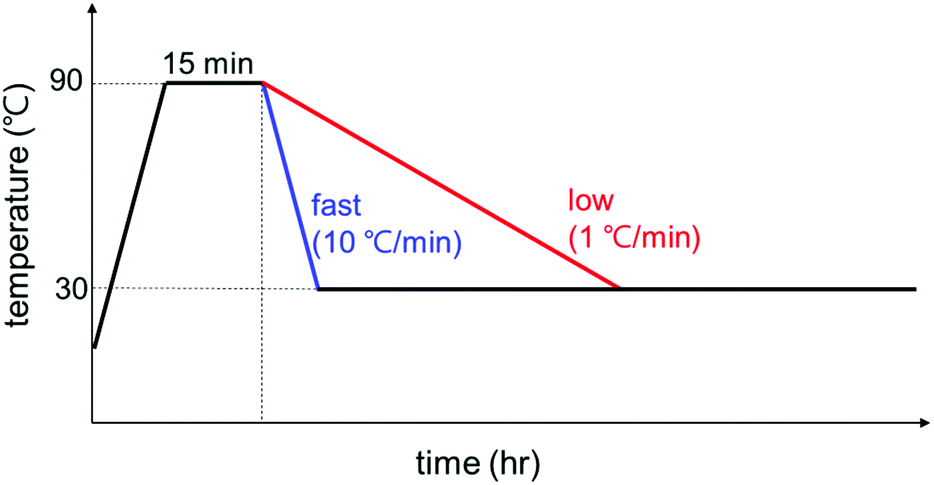 | ||
| Fig. 1 A temperature control profile for polymer crystallization during the experiment. | ||
Polarized optical microscopy (POM)
The LC phase of GO suspension in a dense polymer solution was investigated by POM. The sample was injected into a 1 mm thick glass cell, and images were taken at 50× magnification between two crossed polarizers with an Olympus BX51 M microscope. To control the temperature profile, a Linkam CSS-450 temperature stage was connected to the microscope.Differential scanning calorimetry (DSC)
The DSC measurement was carried out using a differential scanning calorimeter (TA DSC Q2000). First, 5 to 10 mg of the sample was subjected to the temperature profile shown in Fig. 1 and then multiple samples were prepared that have different holding times. Then, the samples with different holding times were heated at a rate of 10 °C min−1 to 90 °C to calculate the degree of crystallinity of PEG in GO/PEG complexes.Synchrotron X-ray characterization
WAXD and SAXS experiments were conducted at the 6D and 9A Beamline of Pohang Accelerator Laboratory (PAL), respectively. For sample preparation, 200 μl of GO/PEG complex was injected at a constant rate (3 ml min−1) into a 1.5 mm thick quartz capillary cell. The scattering length densities of GO and PEG are 5.99 × 10⁻⁶ Å−2 and 0.70 × 10⁻⁶ Å−2, respectively.WAXD experiment provides information about crystallization behavior of polymers at atomic scales. The sample-to-detector distance was 475 mm, and the X-ray energy was 18.986 keV. The scattered X-rays were analyzed with a CCD area detector (MX-225HS, Rayonix LLC). The 2D patterns were azimuthally integrated to a 1D profile of intensity versus scattering vector, q = (4π![[thin space (1/6-em)]](https://www.rsc.org/images/entities/char_2009.gif) sinθ)/λ (2θ is the scattering angle, and λ is the wavelength of X-ray).
sinθ)/λ (2θ is the scattering angle, and λ is the wavelength of X-ray).
To investigate the microstructure of GO LC with polymer crystals, the SAXS experiment was performed. The sample-to-detector distance was 4605 mm, and the X-ray energy was 11.045 keV. The scattered X-rays were analyzed with a CCD area detector (Rayonix SX165, USA).
Results and discussion
GO LC with polymer crystallization was observed at GO concentrations of 0.3 and 1.5 wt%. The samples were heated up to 90 °C above the melting temperature of PEG 3350 (Tm = 54–58 °C) and cooled at different rates as shown in Fig. 1. For simplicity, the samples are labeled based on the GO concentration and the cooling rate as ‘GP concentration-cooling rate’. For instance, GP03-fast (GP03-slow) stands for a GO/PEG sample containing GO 0.3 wt% and was crystallized at a cooling rate of 10 (1 °C min−1). The polymer concentration was constant at 80 wt% in all samples. We performed Raman spectroscopy to check for possible chemical reduction of GO during heating/cooling and the result showed no changes in the GO function/structure during the crystallization process of PEG (Fig. S1 in ESI†).Macroscopic GO LC behavior with polymer crystallization
The macroscopic GO LC structure and polymer crystallization were investigated through POM (Fig. 2). Fig. 2 shows the changes in POM images for ‘GP03’ at different stages of polymer crystallization following the temperature profile given in Fig. 1. Before the crystallization at a high temperature of 90 °C, the typical LC texture from the birefringence of GO LC was seen, indicating that GO forms nematic LC structures. As the polymer crystallization occured at a decreased temperature of 30 °C, the POM image became dark and some typical spherulites were formed. While the reduced birefringence of GO LC may contribute to the reduced brightness in the POM images, the change in the microstructure of GO LC was difficult to observe because of the excess polymers present in the sample. Because the sample states were too thick, the POM images for the film state of samples were additionally obtained after a quick blade-coating. Fig. 2b shows that the slow cooling rate yields a greater degree of birefringence. The POM results confirm the existence of GO LC; however, the delicate change in GO LCs between two cooling rates was more difficult to be analyzed, which were dealt with a SAXS experiment as follow.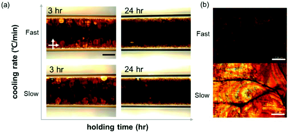 | ||
| Fig. 2 POM images of (a) GO LC in the polymer solution with different polymer crystallizations and (b) birefringence in the film after complete evaporation. The scale bar is 500 μm. | ||
Polymer crystallization with GO LC at controlled cooling rate
Before discussing the detailed microstructure of GO LC with crystallization, we examined the role of GO for polymer crystallization. In the presence of GO, the mobility of polymers can be restricted, especially near the GO surface, whereas the GO surface may provide directionality for polymer crystallization. Thus, one needs to understand how the addition of GO conversely affects PEG crystallization: the crystal structure and kinetics of crystallization. To probe the growth of polymer crystals, in situ WAXD experiments were performed under a temperature-controlled profile. The polymer crystallization was induced by cooling the sample at a rate of 5 °C min−1. Fig. 3a and b show the resulting WAXD profiles for the neat polymer solution and the same polymer solution but with GO, respectively. While the pure PEG solution did not show any crystal peak even after being held at 30 °C for 10 min despite a high PEG concentration of 80%, the GP15 composites had already exhibited the first crystal reflections before even reaching 30 °C. The distinctive crystal peaks found in PEG in the GO solution show the accelerated kinetics of PEG crystallization in the presence of GO. There are two signature peaks located at 2θ = 19° and 23.3°, which arise from (021) and (032) reflections of the PEG crystals with monoclinic unit cells, respectively;26,27 the typical reflections show that the addition of GO did not alter the original PEG crystal structure at the atomic level.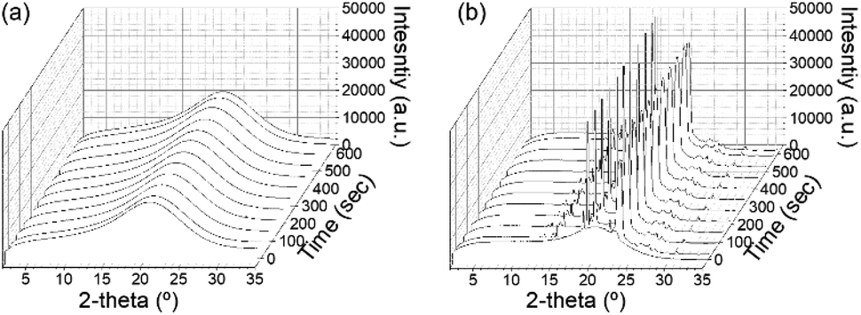 | ||
| Fig. 3 Development of WAXS profiles as a function of holding time for (a) neat PEG solution and (b) PEG solution with 1.5 wt% GO. | ||
The significantly enhanced crystallization of PEG with GO is consistent with the previous study, which reported that the polymer chain could easily align at the GO interface with high specific surface areas,28 reducing the nucleation barrier and thereby exerting a higher degree of PEG crystallization. It additionally noted that strong interfacial adhesion between the polymer chain with a hydroxyl group and GO nanosheets exists.17,18,28
Microscopic GO LC behaviour with polymer crystallization
While the POM experiment confirmed the presence of GO LC and PEG crystallization and WAXD suggested a plausible polymer crystallization at the interface, the detailed microstructure of GO LC and PEG crystallization was still missing. Thus, we extensively performed in situ SAXS experiments to investigate the microstructural change of GO LC with polymer crystallization in more detail. The samples were loaded into 1.5 mm thick capillary cells and loaded with a syringe pump at the same rate of 3 ml min−1 to provide the same degree of the initial shear effect. Once the samples are cooled to 30 °C based on the temperature profile given in Fig. 1, the sample scatterings from GO LC and polymer crystallization were obtained with increasing the holding time.Fig. 4 shows the representative 2D SAXS patterns of the samples after cooling to 30 °C at different times (a complete series of the SAXS results is given in Fig. S2†). As the samples were cooled down, the polymer crystallization occurs simultaneously with GO LC. Noting the critical concentration to nematic LC of GO is around 0.3 wt,20 GO can align and form the LC phase along the longest axis of the capillary cells in a long range confirmed by the stretched 2D SAXS patterns.29
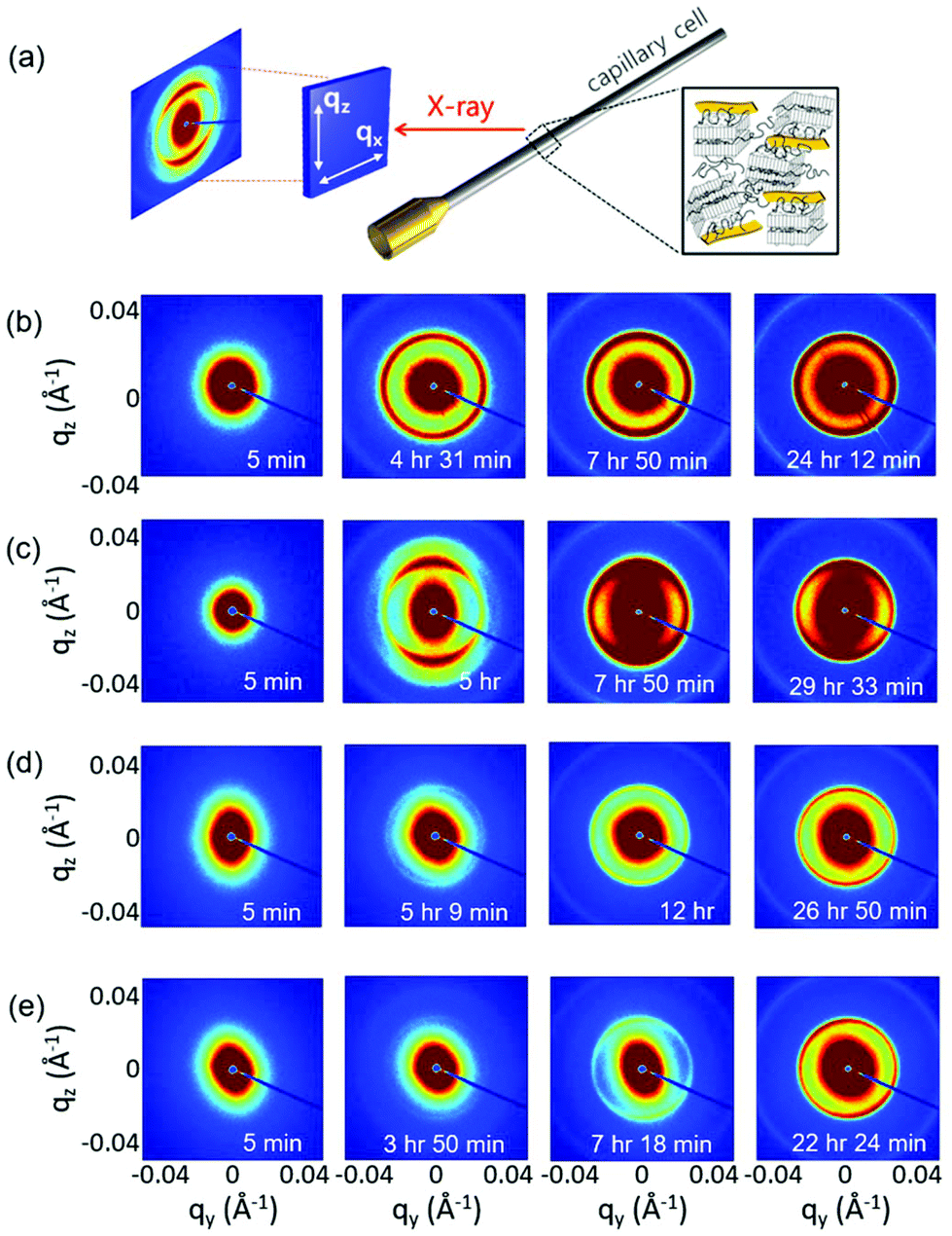 | ||
| Fig. 4 (a) Schematic illustration of SAXS experiment. Selected 2D SAXS pattern of (b) GP03-fast, (c) GP03-slow, (d) GP15-fast, and (e) GP03-slow at different holding times. | ||
However, the long range alignment of GO LC seems to be related to the type of polymer crystallization. In Fig. 4b, when GP03 was crystallized under the fast cooling rate (GP03-fast) to 30 °C, the 2D pattern of GP03-fast was isotropic with the isotropic rings developed from the polymer crystallization. It implies that the directionality and alignment of GO LC were affected by the non-directional growth of polymer crystallization, and thereby the liquid crystallinity of GO was significantly decreased compared to that without polymer crystallization. In contrast, highly asymmetric scattering patterns were obtained at the slow cooling rate of GP03-slow (Fig. 4c). In GP03-slow, 2D SAXS patterns from 5 h to the final state at 30 °C show more stretched patterns along the long axis of a capillary cell with higher intensity.
The effect of the slow cooling rate is less pronounced at the high concentration (GP15) than at the low concentration (GP03). At low concentrations of GP03, different LC behaviour of GO was seen: the isotropic patterns at the fast cooling rate and the anisotropic pattern at the slow cooling rate were found (Fig. 4b and c). However, in the final state of concentrated GP15 where the crystallization was complete over 20 h of holding time, the 2D SAXS patterns show the weakly stretched patterns at both fast and slow cooling rates (Fig. 4d and e). While the liquid crystallinity of GO decreased with PEG crystallization, the decreased degree of GO LC was more or less the same despite the different cooling rates, which require more detailed analysis.
The effect of crystallization kinetics on GO LC
To understand the structural development of PEG crystals more quantitatively, the in situ SAXS profiles are re-examined focusing on scattering features at high q ranges. The scattering intensity was normalized by multiplying q2 considering the two-dimensional nature of GO and thus the Kratky plot (Iq2vs. q) emphasizes the structural information of polymer crystallization. Fig. 5a and b show the Kratky plots of ‘GP03-fast’ and ‘GP03-slow’ at the selected holding times, respectively. Multiple crystal peaks are found arising from the PEG lamellar structures. As shown in Fig. 5a, after 30 minutes, PEG in GP03-fast exhibits the peaks at qold = 0.04/0.08 Å−1, which are the first/second diffraction peaks. The corresponding long period L0 of PEG lamellar stacks was about 15.77 nm (calculated from Bragg's law L0 = 2nπ/qold, where n is the diffraction order and q is the scattering vector), which indicates the twice-folded lamellar structure.15 With further crystallization after 7 h 50 m, PEG showed well-resolved peaks at qnew = 0.026, 0.052 and 0.078 Å−1 with the q ratio of 1:2:3, which indicates the first, second, and third orders of lamellar stacks, respectively. The corresponding long period L0 was about 24 nm, implying the once-folded lamellae. This peak shift phenomenon confirms the well-known unfolding of PEG lamellae from a twice-folded to a once-folded structure.30,31 The lamellar thickening behavior is generally known to occur with low molecular weight PEG and this experiment also confirmed that behavior regardless of the cooling rate and GO concentration (Fig. 5a and b), ensuring that the addition of GO did not change the lamellar thickening trend of PEG crystal.
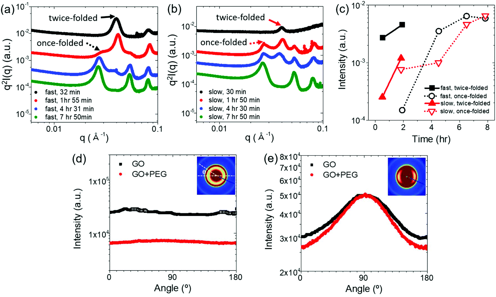 | ||
| Fig. 5 Kratky plots of (a) GP03-fast and (b) GP03-slow. (c) The intensity development at q* at different times of GP03 crystallization. Angle distribution curves of scattering intensity for (d) GP03-fast and (e) GP03-slow at selected holding times of 7 h 50 min. | ||
However, the speed of lamellar thickening was different depending on the cooling rate. Fig. 5c shows the growth rate of PEG crystals at fast and slow cooling rates; we compared the scattering intensity at the qold and qnew (Fig. 5a and b), which indicates twice and once-folded structure, with increasing holding time at 30 °C. The peaks of GP03-fast grew faster than that of GP03-slow did at early times, implying that the PEG in GO suspension crystallized faster at faster cooling rates with higher crystallinity as generally expected in polymer crystallization kinetics. As the system approaches the target temperature faster, more nucleation points are created simultaneously increasing the crystallinity of the polymer. This result was also supported by DSC measurements. In Fig. S3,† the degree of crystallinity of GP03-fast was higher than that of GP03-slow.
One expects that the different degrees of PEG crystallization will certainly influence GO LC. To investigate the effect of the degree of PEG crystallization with varying cooling rates on GO LC and the PEG crystal structure, azimuthal distributions of scattering profiles were obtained at specific q-ranges, qGO = 0.004–0.02 Å−1 and qPEG = 0.016–0.036 Å−1. The range of qGO = 0.004–0.02 Å−1 is chosen where the PEG crystal peaks did not appear; thus the structural information on GO LC is dominant (black symbol in Fig. 5d and e). In contrast, the structural information on PEG crystals is more dominant in the range of qPEG = 0.016–0.036 Å−1 where the distinctive crystal peaks are present along with the scatterings from GO (red symbol in Fig. 5d and e).
Fig. 5d and e compare the directionality of GO LC and PEG crystallization of GP03 depending on the cooling rates. After 7 h 50 m of cooling, the scattering of GP03-fast is evenly distributed for angle in both q ranges, consistent with the isotropic scattering pattern (Fig. 5d). In fast cooling, PEG begins to crystallize simultaneously in bulk with multiple nucleation points. As the PEG crystals rapidly grow non-directionally under the fast cooling rate, the GO is swept away by the PEG crystallization growth and thus cannot form LC despite GO03 being at the critical nematic LC concentration. The angle distributions of GO15 are given in Fig. S5.†
However, the scattered intensity of GP03-slow (Fig. 5e) in the same time scale exhibits a sharp peak at 90° in both q ranges. The directionality found in both qGO and qPEG ranges implies that the GO is aligned along the long axis of the capillary sample cell in a long range, which more importantly guided the crystal growth of the PEG as well. The asymmetric distribution of PEG crystal growth shows that PEG in GO suspension prefers to crystallize on the surface of GO at a slow cooling rate. Unlike the bulk PEG crystallization with the fast cooling rate, interfacial crystallization of PEG is found with the slow cooling rate. More interestingly, the slow growth of PEG crystals seemed to help GOs to align one another, improving the directionality of GO LC.
A similar dependency of cooling rates on GO LC is found for a high concentration of GP15. In the absence of PEG crystallization, the nematic transition concentration of GO is around 0.3 wt% and thus the nematic LC is readily formed at a sufficient concentration of 1.5 wt% in the long range. Considering that the macroscopic directionality of GO LC is directly related to the physical properties of the GO-based composites, this observation could provide an idea to control the microstructure of GO LC in polymer matrices.
Microscopic evolution for lamellar thickness of PEG and d-spacing of GO at different cooling rates
As the crystallization kinetics changes the macroscopic ordering of GO LC, it additionally affects the microscopic structure of PEG crystals and the GO-layering (d-spacing) structures. Thus, in this part, the lamellar thickness and d-spacing between GO sheets were calculated and compared for different cooling rates. Fig. 6a and b show the development of the lamellar thickness, L0 calculated from the first peak of the once-folded lamellae, q* during the selected holding times at 30 °C for GP03 and GP15, respectively (the q* developments are given in Fig. S6†).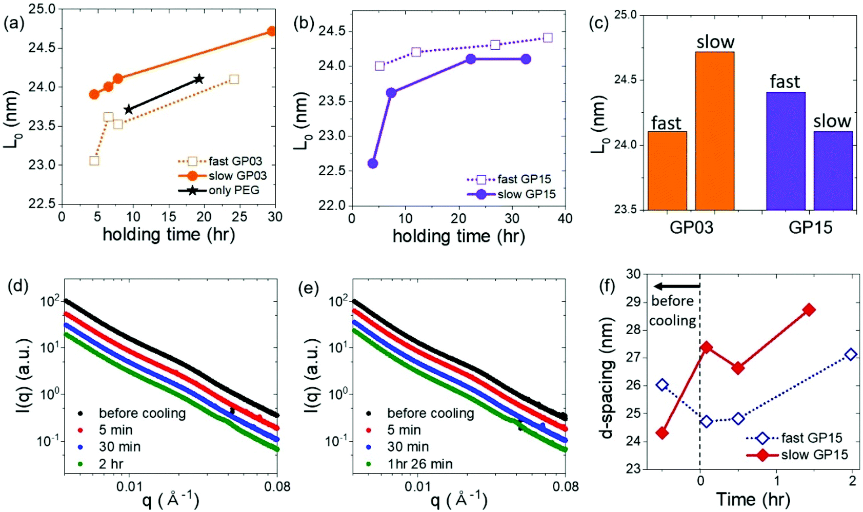 | ||
| Fig. 6 The long period of crystal lamellae as a function of holding time for (a) GP03 and (b) GP15. (c) The calculated lamellae thickness after complete crystallization of GP03 and GP15. The 1D profile of (d) GP15-fast and (e) GP15-slow at early times. (f) Interlayer spacing of GO with varying holding time for different cooling rates. | ||
For GP03 in Fig. 6a, the L0 for slow cooling (filled) is always higher than that for fast cooling (unfilled); the lamellar thickness of PEG was slightly thicker at GP03-slow than at GP03-fast as shown in Fig. 6c. As the slow cooling rate led to the interfacial growth of the PEG crystal on the surface of GO, it ultimately increased the lamellar thickness of the PEG crystal. Conversely, at the fast cooling rate, PEG crystals are likely to grow randomly in the bulk polymer matrix, and thus the crystal growth can be restricted by the presence of other nearby crystals to a small degree, which simultaneously prevents GO from forming a stable LC phase at the fast cooling rate.
For concentrated GP15 shown in Fig. 6b, the thickness of PEG lamellae, in contrast to GP03, was thicker at the fast cooling rate. For GP15, the GO–GO layer spacing is reduced close to the size of PEG lamellae, and therefore, the interfacial growth of PEG crystals is rather restricted by nearby GO sheets. This confinement effect by GO sheets, in turn, decreased the size of the PEG lamellae and the bulk PEG crystallization with fast cooling results in slightly thicker lamellae without confinement.
Next, we observed the change in the interlayer distance between GO sheets during polymer crystallization at different cooling rates. As the crystal peaks are developed, the GO scattering profile is buried, thus, the information of GO spacing is discussed only for early times. The samples were initially at 90 °C and cooled down to 30 °C. Fig. 6d and e show the scattering intensity of GP15-fast and slow at a different stage of PEG crystallization, respectively. The average plane-to-plane distance, d-spacing is obtained from the peak position, q* (d-spacing = 2π/q*). As the polymer crystallization further proceeds, the d-spacing generally increases in both cooling rates (Fig. 6e) because the growing polymer crystals push GO sheets away, thereby slightly interrupting the liquid crystallinity of GO. Intriguingly, the d-spacing at the slow cooling rate was larger than that at the fast cooling rate, presumably due to the interfacially-grown PEG crystals. Finally, we present the schematic images of GO LC behaviour with polymer crystallization under different cooling rates and GO concentrations in Fig. 7. The degree of liquid crystallinity is indicated with the brightness in the yellow bar. GP03-fast shows the lowest liquid crystallinity of GO and GP03-slow has the highest liquid crystallinity of GO. The interfacial crystallization at a slow cooling rate improved GO LC while the bulk crystallization at a fast cooling rate increased GO LC. For GP15, the GO LCs in GP15-fast and slow were not significantly different; however, the random growth of PEG crystallization in bulk with a fast cooling rate rather decreased the GO–GO interlayer spacing.
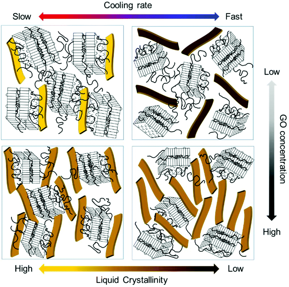 | ||
| Fig. 7 Schematic images of GO LC with polymer crystal structure cooling at fast and slow speed. | ||
Conclusion
In this study, we have thoroughly investigated the effect of crystallization kinetics on the microstructure of GO LCs through extensive time-resolved scattering analysis. Based on the general perception that the addition of GO fillers improves the physical properties of polymer composites, we found that there is a more delicate interaction between GO LCs and PEG crystallization.Depending on the crystallization kinetics, PEG with GO prefers to crystallize at the interface or in bulk, which ultimately changes the primary direction of GO LC. We believe that this study will provide a significant insight to control the filler direction in potential GO-based polymer composites. We emphasize that polymer crystallization is certainly beneficial to improve the physical properties of neat polymers; however, the control of GO LC correlated with polymer crystallization should be simultaneously realized to design high-performance polymer composite materials at a more practical level for GO applications.
Author contributions
The manuscript was written through the contributions of all authors. All authors have approved the final version of the manuscript.Conflicts of interest
There are no conflicts to declare.Acknowledgements
This work was supported by the National Research Foundation of Korea (NRF) grant funded by the Korea government (MSIT) (NRF-2016M3A7B4905624 and NRF-2018R1A5A1024127. WAXD and SAXS measurements were performed at the PLS-II 9A U-SAXS beamline and 6D UNIST-PAL beamline of the Pohang Accelerator Laboratory (PAL) in Pohang, Korea, respectively, and those experiments were supported in part by MSIT, POSTECH, and UNIST UCRF.References
- C. Cheng and D. Li, Adv. Mater., 2013, 25, 13–30 CrossRef CAS.
- R. Narayan, J. E. Kim, J. Y. Kim, K. E. Lee and S. O. Kim, Adv. Mater., 2016, 28, 3045–3068 CrossRef CAS.
- D. A. Dikin, S. Stankovich, E. J. Zimney, R. D. Piner, G. H. B. Dommett, G. Evmeneko, S. T. Nguyen and R. S. Ruoff, Nature, 2007, 448, 457–460 CrossRef CAS.
- A. Corker, H. C. Ng, R. J. Poole and E. Garcia-Tunon, Soft Matter, 2019, 15, 1444–1456 RSC.
- H. Cong, P. Wang and S. Yu, Chem. Mater., 2013, 25, 3357–3362 CrossRef CAS.
- M. J. Noh, M. J. Oh, J. H. Choi, J. C. Yu, W. Kim, J. Park, Y. Chang and P. J. Yoo, Soft Matter, 2018, 14, 6708–6715 RSC.
- X. Yun, B. Lu, Z. Xiong, B. Jia, B. Tang, H. Mao, T. Zhang and X. Wang, RSC Adv., 2019, 9, 29384–29395 RSC.
- K. Zhou, C. Chen, M. Lei, Q. Gao, S. Nie, X. Liu and X. Wang, RSC Adv., 2020, 10, 2150–2159 RSC.
- J. Kim, S. W. Kim, H. Yun and B. J. Kim, RSC Adv., 2017, 7, 30221–30228 RSC.
- C. Danda, L. G. Amurin, P. A. R. Munoz, D. A. Nagaoka, T. Schneider, B. Troxell, S. Khani, S. H. Domingues, R. J. E. Andrade, G. J. M. Fechine and J. M. Maia, ACS Appl. Mater. Interfaces, 2020, 3, 9694–9705 CrossRef CAS.
- H. J. Jung, S. P. Sasikala, K. E. Lee, H. S. Hwang, T. Yun, I. H. Kim, S. H. Koo, R. Jain, G. S. Lee, Y. H. Kang, J. G. Kim, J. T. Kim and S. O. Kim, ACS Cent. Sci., 2020, 6, 1105–1114 CrossRef CAS.
- C. Yeh, H. Huang, A. T. O. Lim, R. Jhang, C. Chen and J. Huang, Nat. Commun., 2019, 10, 442 CrossRef.
- S. Cheng, X. Chen, Y. G. Hsuan and C. Y. Li, Macromolecules, 2011, 45, 993–1000 CrossRef.
- H. Huang, J. Xu, Y. Fan, L. Xu and Z. Li, J. Phys. Chem. B, 2013, 117, 10641–10651 CrossRef CAS.
- K. Liu, E. L. de Boer, Y. Yao, D. Romano, S. Ronca and S. Rastogi, Macromolecules, 2016, 49, 7497–7509 CrossRef CAS.
- H. Xu, D. Wu, X. Yang, L. Xie and M. Hakkaranien, Macromolecules, 2015, 48, 2127–2137 CrossRef CAS.
- J. Xu, C. Chen, Y. Wang, H. Tang, Z. Li and B. S. Hsiao, Macromolecules, 2011, 44, 2808–2818 CrossRef CAS.
- J. Xu, Y. Liang, G. Zhong, H. Li, C. Chen, L. Li and Z. Li, J. Phys. Chem. Lett., 2012, 3, 530–535 CrossRef CAS.
- S. Cheng, D. M. Smith and C. Y. Li, Macromolecules, 2015, 48, 4503–4510 CrossRef CAS.
- Y. H. Shim, K. E. Lee, T. J. Shin, S. O. Kim and S. Y. Kim, Mater. Horiz., 2017, 4, 1157–1164 RSC.
- Y. H. Shim, K. E. Lee, T. J. Shin, S. O. Kim and S. Y. Kim, ACS Nano, 2018, 12, 11399–11406 CrossRef CAS.
- S. J. Kim, D. W. Kim, K. M. Cho, K. M. Kang, J. Choi, D. Kim and H. T. Jung, Sci. Rep., 2018, 8, 1959–1967 CrossRef.
- M. P. Godfrin, F. Guo, I. Chakraborty, N. Heeder, A. Shukla, A. Bose, R. H. Hurt and A. Tripathi, Langmuir, 2013, 29, 13162–13167 CrossRef CAS.
- J. E. Kim, T. H. Han, S. H. Lee, J. Y. Kim, C. W. Ahn, J. M. Yun and S. O. Kim, Angew. Chem., Int. Ed., 2011, 50, 3043–3047 CrossRef CAS.
- P. Kumar, U. N. Maiti, K. E. Lee and S. O. Kim, Carbon, 2014, 80, 453–461 CrossRef CAS.
- M. Pulst, M. H. Samiullah, U. Baumeister, M. Prehm, J. Balko, T. Thurn-Albrecht, K. Busse, Y. Golitsyn, D. Reichert and J. Kressler, Macromolecules, 2016, 49, 6609–6620 CrossRef CAS.
- M. S. Lisowski, Q. Liu, J. Cho and J. Runt, Macromolecules, 2000, 33, 4842–4849 CrossRef CAS.
- B. P. Grady, F. Pompeo, R. L. Shambaugh and D. E. Resasco, J. Phys. Chem. B, 2002, 106, 5852–5858 CrossRef CAS.
- Z. Xu and C. Gao, Nat. Commun., 2011, 2, 571–579 CrossRef.
- T. V. Duong, B. Goderis, J. V. Hunbeeck and G. V. der Mooter, Mol. Pharmaceutics, 2018, 15, 629–641 CrossRef.
- C. Buckley and A. Kovacs, Colloid Polym. Sci., 1976, 254, 695–715 CrossRef CAS.
Footnote |
| † Electronic supplementary information (ESI) available. See DOI: 10.1039/d0nr07858a |
| This journal is © The Royal Society of Chemistry 2021 |