
Switching to the brighter lane: pathways to boost the absorption of lanthanide-doped nanoparticles
Riccardo
Marin
*a,
Daniel
Jaque
 ab and
Antonio
Benayas
*ab
ab and
Antonio
Benayas
*ab
aFluorescence Imaging Group (FIG), Departamento de Física de Materiales, Facultad de Ciencias, Universidad Autónoma de Madrid, C/Francisco Tomás y Valiente 7, Madrid 28049, Spain. E-mail: riccardo.marin@uam.es; antonio.benayas@uam.es
bNanobiology Group, Instituto Ramón y Cajal de Investigación, Sanitaria Hospital Ramón y Cajal, Ctra. de Colmenar Viejo, Km. 9100, 28034 Madrid, Spain
First published on 23rd December 2020
Abstract
Lanthanide-doped nanoparticles (LNPs) are speedily colonizing several research fields, such as biological (multimodal) imaging, photodynamic therapy, volumetric encoding displays, and photovoltaics. Yet, the electronic transitions of lanthanide ions obey the Laporte rule, which dramatically hampers their light absorption capabilities. As a result, the brightness of these species is severely restricted. This intrinsic poor absorption capability is the fundamental obstacle for untapping the full potential of LNPs in several of the aforementioned fields. Among others, three of the most promising physicochemical approaches that have arisen during last two decades to face the challenges of increasing LNP absorption are plasmonic enhancement, organic-dye sensitization, and coupling with semiconductors. The fundamental basis, remarkable highlights, and comparative achievements of each of these pathways for absorption enhancement are critically discussed in this minireview, which also includes a detailed discussion of the exciting perspectives ahead.
 Riccardo Marin | Riccardo Marin obtained his PhD in Chemistry jointly from the University Ca’Foscari (Venice, Italy) and the Institut National de la Recherche Scientifique (INRS-Varénnes, Canada) under the supervision of Prof. P. Canton and Prof. F. Vetrone. He then undertook a postdoctoral fellowship at the University of Ottawa from 2017 to 2019 with Prof. E. Hemmer and Prof. M. Murugesu. He is currently a Marie Skłodowska-Curie fellow at the Universidad Autónoma de Madrid in the group of Prof. D. Jaque. His research interests encompass the development and study of optically active (nano)materials based on lanthanide ions and semiconductors. |
 Daniel Jaque | Daniel Jaque got his PhD in Physics from Universidad Autónoma de Madrid (UAM, Spain) in 1999. After a decade of outstanding research on laser materials and photonics, he founded the Fluorescence Imaging Group together with Prof. J. García Solé in 2010, which has been working to develop luminescent materials nanomaterials of different kinds (quantum dots, lanthanide doped nanoparticles, etc.) towards applications ranging from optical trapping to biomedical imaging. Prof. Jaque was a pioneer from the dawn of luminescence thermometry; today, he is a world-renowned leader in the in vivo application of this technique. |
 Antonio Benayas | Antonio Benayas was awarded his PhD “cum laude”—Physics of Light and Matter—at Universidad Autónoma de Madrid (UAM, Spain) in 2012. His research then shifted to near-infrared emitting luminescent nanoparticles, supported by health-related funding agencies to join the group led by Prof. Vetrone (INRS, Canada). Later on, he worked at Stanford School of Medicine (USA) with Prof. J. Rao, and at Aveiro Materials Institute (CICECO, Portugal) joining forces with Prof. L. Carlos; both of those terms were supported by a Marie Skłodowska-Curie Action (European Commission). By mid-2020 Dr Benayas joined his alma mater (UAM), thus starting a tenure-track contract. |
1. Introduction
Despite suggestions of turning the periodic table upside down,1 lanthanides (from the Greek word lanthaneien meaning “lying hidden”) continue to occupy the bottom part of it together with their bigger brothers, namely actinides. This representation makes lanthanides quite literally “outstanding” elements but not only for their unique properties. Lanthanides, which along with scandium and yttrium form the family of rare earths, are indeed elements of strategic interest for several applications. Anti-counterfeiting tags in banknotes, blue-light conversion layer in LEDs, permanent magnets, and lighter flints are some of the mundane objects containing lanthanides that cross our paths on a daily basis. Other materials are more exotic, such as lanthanide complexes behaving as magnets at the single-molecule level (single-molecule magnets-SMMs).2,3 However, herein, we are interested in a particular family of materials that capitalize on the light emitted by trivalent lanthanide ions (Ln3+); colloidal nanoparticles doped with Ln3+ (LNPs). LNPs are the workhorses in several fields of nanotechnology owing to their capability, for example, to act as optical probes4–6 and photo-initiate chemical reactions under excitation with low-energy photons.7,8 The small size of LNPs makes them usable in microenvironments (e.g., cells)9 and more generally for the investigation of phenomena with sub-micrometric accuracy while minimally perturbing the observed system.10,11 They have also been proposed for the preparation of light harvesting layers for low-energy photons, which would otherwise go unexploited in photovoltaic devices.12,13 All in all, LNPs have deservedly gained a place of respect in the field of nanotechnology alongside their older kin featuring photoluminescence properties—the family of semiconductor nanocrystals. LNPs and semiconductor nanocrystals are both inorganic luminescent nanoparticles. However, the similarities between them end there. Numerous discrepancies exist in terms of chemistry and physics, making each of these nanomaterials suited for specific applications where the other might need to stretch. Hence, LNPs and semiconductor nanocrystals are complementary rather than competing both with their advantages and shortcomings. Speaking of the latter, the most notable limitation of LNPs resides in their low overall emission intensity, which is the result of the electronic configuration of Ln3+ ions (vide infra). This poor brightness represents a major bottleneck in the widespread employment of LNPs in fields such as lighting and optical imaging. However, brighter LNPs would also translate to better performance in applications where these species are already routinely employed, such as in the field of sensing. Given the central role played by brightness in the context of this minireview, it is convenient to provide its rigorous definition from the very beginning, i.e., the product of molar absorption coefficient and photoluminescence quantum yield (PLQY). In layman terms, these two quantities define the efficiency of a species in absorbing and emitting photons.In this review, we discuss the recent advances in the development of brightly-emitting LNPs through the improvement of their absorption. In Section 2, we present in simple and comprehensive terms the “brightness issue” that affects Ln3+ luminescence. We then proceed to Section 3 to critically review the methods developed so far for tackling this issue. Although several approaches have been proposed, we herein focus on three specifically: the use of plasmonic moieties to increase the absorption (and emission) prowess of Ln3+, and the sensitization of Ln3+ emission through the use of organic dyes and semiconductors. Lastly, in Section 4, we provide an overview of the field, pinpointing the questions still unresolved, also identifying the most promising and probable future research directions.
2. Lanthanide ions and their forbidden transitions
Trivalent lanthanides (Ln3+) owe most of their properties to non-bonding electrons occupying the 4f orbitals.14,15 Precisely because of this lack of involvement of 4f electrons in the formation of bonds, at the single-ion level, Ln3+ feature remarkably similar physical properties in vacuo and when bound to other elements to form compounds. The “ladder” of the 4f electronic states of each Ln3+ (Fig. 1) is in fact screened by external charge densities from the 5s and 5p orbitals. Thus, the electrons can jump undisturbed between the steps of the 4f ladder; however, they should obey an important quantum mechanics constraint, namely, the parity (Laporte) rule.16 This rule states the impossibility of electronic transitions between states with the same parity (such as 4f–4f intraconfigurational transitions) to occur in centrosymmetric environments. Fortunately, even when a Ln3+ is placed at the centre of a perfectly centrosymmetric coordination polyhedron, f–f electronic transitions can still occur thanks to vibrations that induce a temporary reduction of the symmetry. Moreover, admixing with opposite-parity wavefunctions (e.g., 5d orbitals and/or coordinating ligands) can also cause the breakdown of this selection rule. Of course, the forbidden nature of these transitions decreases the probability of an electron to be excited to a higher-energy state as well as relax to a less energetic one. Therefore, when (and if) an electron is promoted by the absorption of a photon to a higher step of the ladder, it will sit there for a relatively long time (micro- to milliseconds) before being kicked up to an even more energetic state or relaxing to a lower lying one. Under the right conditions, such relaxation is accompanied by the release of energy in the form of a photon whose energy matches the energy difference between the initial and final states, rather than as heat generated by vibrations. Overall, the unique electronic configuration of Ln3+ results in emissions that are narrow (atom-like), fall at relatively constant energies (changing by few hundred wavenumbers at most), and have extended lifetimes. The long-lived nature of the 4f electronic states is desirable since it can be harnessed to generate the optical phenomenon of upconversion (UC). This process entails the sequential absorption of multiple low-energy photons, followed by radiative relaxation of the excited electron with the emission of a single higher-energy photon.17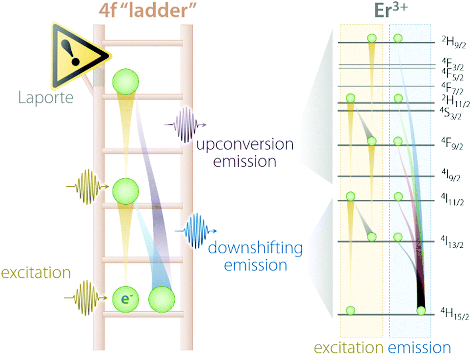 | ||
| Fig. 1 Schematic representation of the “4f ladder” featured by Ln3+ ions, along with the real example of Er3+ excitation and emission processes under 980 nm excitation. | ||
However, the reduced probability of these transitions also translates to poor light absorption and thus to low brightness. From an optical standpoint, this is the more relevant shortcoming of Ln3+ ions since it limits the effectiveness of the direct excitation of 4f electrons responsible for emission. Quantitatively, the capability to absorb a photon of specific energy (i.e., wavelength) is defined by the molar extinction coefficient, which is expressed in units of length per mole. This parameter is of the order of 0.1–10 M−1 cm−1 for Ln3+, while semiconductor nanocrystals and organic dyes feature much larger values in the 104–106 M−1 cm−1 range. The product of this parameter and the PLQY (# of emitted photons per # of absorbed photons) gives the brightness of a species, as previously defined. This is arguably the most important parameter to consider for practical uses as it provides an estimate of how much of the excitation light shined on the luminescent species will eventually be converted to emitted light. However, not all Ln3+ are the same. Some, such as Nd3+ and Yb3+, can absorb light more effectively than others and are thus used as sensitizers, i.e., ions that absorb the excitation light and transfer this energy to the emitting ion (activator). The use of sensitizer–activator pairs is at the basis of the preparation of LNP with good emission brightness. However, more sophisticated strategies have been developed to improve on this concept. In the next section, we discuss selected approaches for the enhancement of this parameter in nanoparticles doped with Ln3+ ions, which aim at increasing the excitation light absorption capability of the nanostructure.
To complete this brief overview of the absorption capabilities of Ln3+, it should be noted that there are exceptions to the cases discussed thus far. Among others, Ce3+ and Eu2+ (divalent europium) are the most relevant lanthanide ions that feature 4f–5d electronic transitions. These transitions are allowed and, as such, yield relatively good light absorption.18,19 Therefore, in such instances, the “brightness issue” is a less urging concern.
3. Strategies to enhance the brightness of Ln3+ nanophosphors
Several researchers have been working on the optimization of LNP-based nanosystems with the goal of maximizing the amount of light absorbed and the fraction of energy funnelled to the activator ion (Fig. 2). This effort resulted in the development of several approaches. Some of them entail the introduction of lattice distortion-inducing ions (Fig. 2A)20–22 and preparation of multi-shell structures (Fig. 2B).23–28 The former approach aims to manipulate the crystal field experienced by the Ln3+ ion, increasing the f–f electronic transition probabilities by the partial admixing of 4f wavefunctions with opposite-parity ones (i.e., 5d orbitals). The latter approach is instead underpinned by concepts such as the maximization of sensitizer concentration, spatial segregation of ions, and surface passivation of the LNP. These approaches push the limit of intrinsic Ln3+ optical properties and are not discussed in the present review; the interested reader is encouraged to read the above cited works. Another strategy entails the co-doping of Ln3+ with ions featuring allowed electronic transitions, such as Ce3+,29,30 Bi3+,31 and Mn3+/4+,32 which can more effectively absorb light and transfer it to nearby activators (Fig. 2C). These allowed electronic transitions occur with the involvement of orbitals that participate in the formation of chemical bonds, unlike the previously mentioned 4f orbitals. For this reason, the energy of the associated electronic levels (and thus the absorption range) can be tailored via the selection of the host material and/or tuning of its composition.18 These ions can also introduce additional energy levels that act as intermediate states for the population of Ln3+, thus increasing the energy transfer efficiency and enabling the fine tuning of the emission colour. In this review, we do not examine these approaches.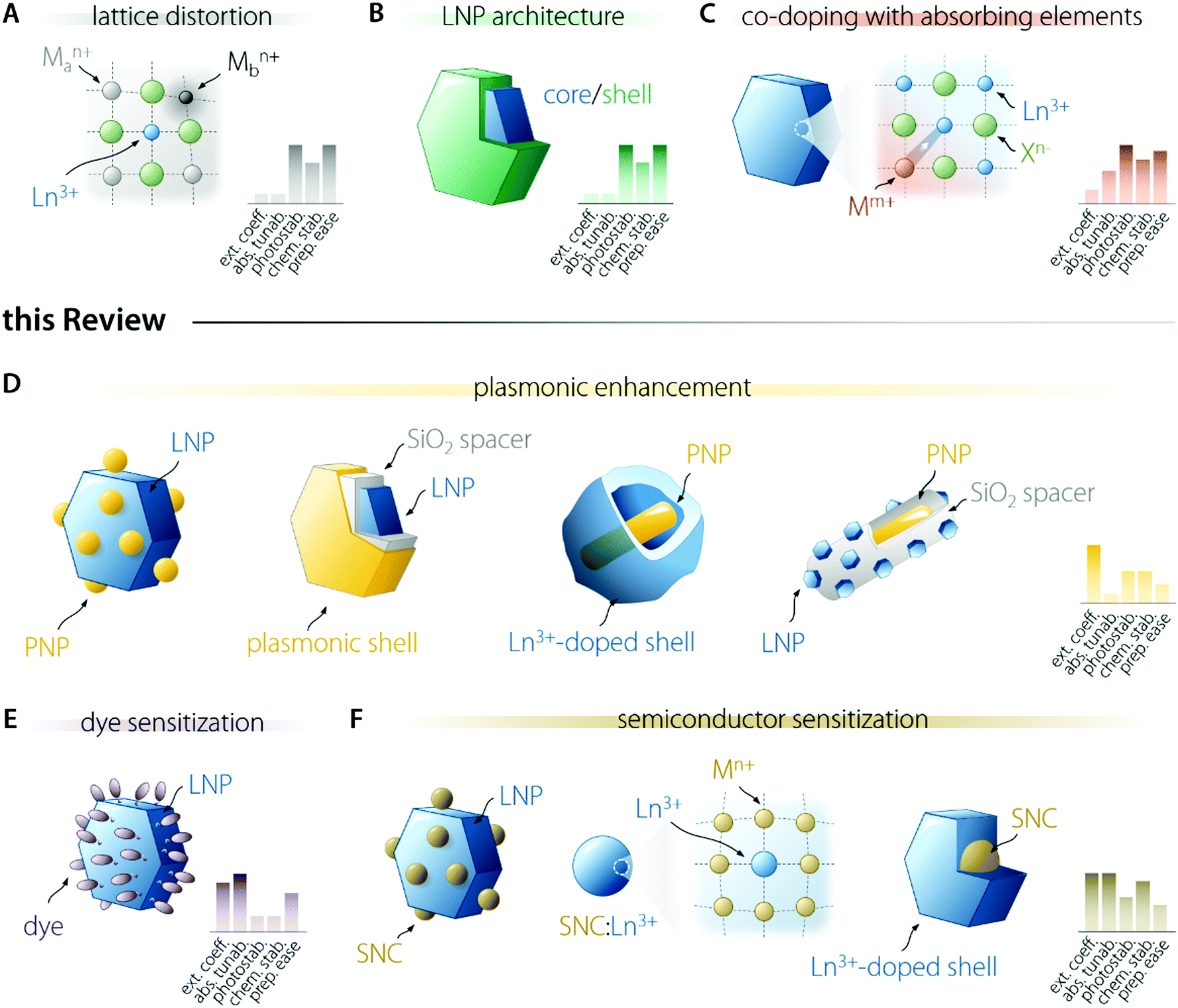 | ||
| Fig. 2 Graphical summary of the strategies employed for the enhancement of Ln3+ emission brightness. (A) The modification of the lattice by the incorporation of defects and lattice-distorting ions effectively lowers the coordination symmetry of Ln3+, ultimately leading to a relaxation of the parity rule for intraconfigurational f–f transitions. (B) Preparation of LNPs with multi-shell architecture, where different Ln3+ ions are spatially confined and protected from quenchers (e.g., solvent molecules with high-energy vibrations) allows minimizing energy losses, thus yielding brighter Ln3+ emission. (C) Co-doping with Ln3+ and ions featuring allowed electronic transitions (Ce3+, Bi3+…) is a viable strategy to enhance the light absorbing capability of LNPs. These approaches (A–C), albeit easy realized, theoretically afford a limited enhancement of the LNP capability to absorb the excitation light. For this reason, in this review we focus on three other approaches that can theoretically grant brighter Ln3+ luminescence. (D) Plasmon-enhancement entails the use of moieties featuring localized surface plasmon resonance (LSPR), which can improve both the absorption and emission efficiency of the coupled LNP. (E, F) Dyes and semiconductors can both be used as excitation light harvesters and, upon proper coupling/amalgamation with LNPs, they can transfer the absorbed energy to Ln3+. These three latter strategies promise the highest absorption enhancement and tunability but the synthesis of these nanosystems require a higher degree of finesse. | ||
In the following sections, we focus our attention on three strategies. One of them acts via the enhancement of the intrinsic absorption (and emission) probability of the Ln3+ ions doped into a material, i.e., the use of plasmonic nanostructures (Fig. 2D). The other two rely on light harvesting moieties of different nature—organic dyes (Fig. 2E) and semiconductor nanocrystals (SNCs – Fig. 2F). For each strategy, we outline the general principle at its basis, passing then to the description of the involved physical processes and the listing of the requirements to be met to successfully prepare a brightly emitting colloidal LNP following the selected strategy.
3.1. Plasmonic enhancement
Among the alternatives discussed in this review, the use of plasmonic materials is by far the most explored pathway for the enhancement of LNPs’ emission. A plasmon is a quasiparticle that defines the collective motion of free charge carriers within a conductor material (e.g., metals), which occurs at a frequency characteristic of the material itself. Surface plasmon (polaritons) resonances (SPR) result from the hybridization of the bulk plasmons with free-space radiation, which takes place at the interface of the plasmonic material and a dielectric medium. Along with the nature of the conducting material, the dielectric constant of the medium determines the oscillation frequency of the charge carriers. When the carriers are spatially confined, as is the case for plasmonic nanoparticles (PNP), the natural frequency of these collective oscillations also depends on the size and geometry of the PNP. This is referred to as localized surface plasmon resonance (LSPR) and is the phenomenon of interest in the current frame. In fact, although there are numerous examples of UC emission enhancement using patterned plasmonic surfaces and 2D structures,33,34 we are herein focusing only on colloidal systems. Clearly, for preparing such systems, PNPs ought to be used.The enhancement of Ln3+ emission stems from the influence of surface plasmons on three distinct parameters, which synergistically contribute to determining the overall emission brightness: decay rates (i.e., radiative and non-radiative relaxations), energy transfer coefficients, and absorption cross-section.35 We should note here that albeit the focus of this review is the betterment of the absorption capability of the LNPs, to comprehensively address the topic of plasmon-enhanced emission, we also discuss the cases wherein increased radiative decay rate plays a major role. Indeed, often the effects cannot be completely disentangled and other times the explanation offered by the authors for the observed emission enhancement is more an “educated guess” than a definitive explanation.
An in-depth discussion of the fundamentals of each aspect lies beyond the scope of this manuscript and the interested reader is encouraged to read the instructive review from Park et al.35 For the sake of the present discussion, it is sufficient to say that (i) absorption is mainly influenced by the local field enhancement, (ii) radiative decay rate is enhanced by the increased photon density of the states (Purcell effect), (iii) non-radiative relaxation is impacted by ohmic losses induced by the presence of metal, (iv) experimental reports indicate that energy transfer enhancement is generally observed for systems with large donor–acceptor separation distance and as such featuring intrinsically inefficient transfer. Regarding the last point, in the case of LNPs, the donor–acceptor distance refers to the separation between the sensitizer and activator ions in the particle lattice. Considering the large amount of sensitizers introduced in LNPs (often between 20 and ∼100%),36 the average distance between the neighbouring ions is short, making the energy transfer between them efficient enough so that its further enhancement using plasmonic moieties is difficult to achieve.37 Importantly, the interplay between the first three points yields an emission enhancement factor whose maximum falls at a specific separating distance between LNP and PNP.38 This distance defines the optimal thickness of the spacer between the two moieties (Fig. 3A – generally of the order of 10 to few tens of nanometres). In the case of LNP–PNP coupling, such a spacer is often made of silica;38–42 however, polymers have also been used.43,44 Another important aspect to consider is that larger PNPs always feature stronger scattering of light, which induces higher luminescence enhancement compared to their smaller counterpart.45,46 For smaller particles, the LSPR peak overlaps with the emission support instead of a more efficient quenching of the luminescence via energy transfer (likely due to their dominant absorption over scattering).47 This is a pivotal consideration, which provides further guidelines for the design of the most suitable plasmonic system for plasmon-enhanced luminescence.
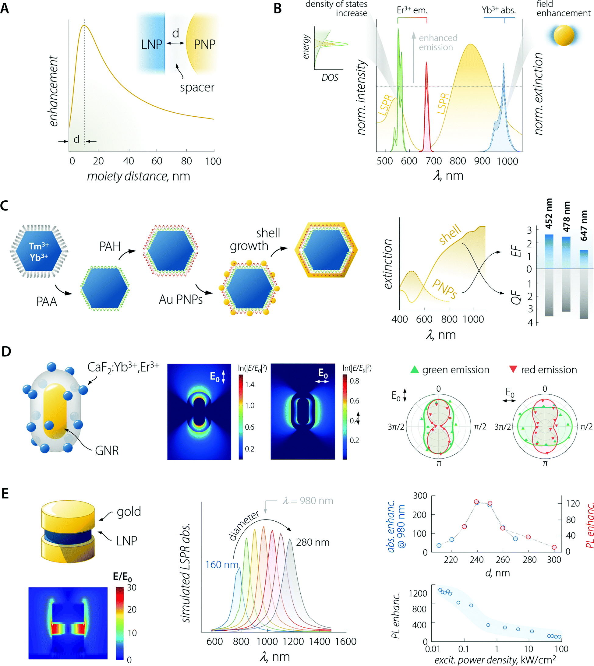 | ||
| Fig. 3 Plasmon-enhanced LNP emission. (A) The enhancement factor is a complex function of the PNP–LNP separation distance with its maximum falling at a value determined by several effects discussed in the main text. (B) Plasmon-enhancement in a Yb3+/Er3+ upconversion system, where absorption (due to local field enhancement) and emission (due to the Purcell effect) are simultaneously achieved. (C) Scheme of sequential decoration of Yb3+/Tm3+-doped LNP with gold nanospheres and the complete coverage with a gold nanoshell, along with the extinction spectra and enhancement/quenching factors observed for the two architectures. Adapted with permission from ref. 53. Copyright 2010 Wiley-VCH. (D) Decoration of a single SiO2-coated GNR with CaF2-based small LNPs. Local field enhancement under 980 nm excitation varies considerably in intensity and spatial distribution, depending on the relative orientation of the impinging light (E0) and the GNR. The different behaviour of the observed polarization of green and red emitted light arises mainly from the coupling between LSPR and UC emission rather than from laser polarization. Adapted with permission from ref. 39. Copyright 2016 Springer-Nature. (E) In a structure comprised of LNPs sandwiched between gold nanodisks, the field (980 nm) is greatly enhanced within the LNPs. Moreover, the position of the LSPR peak of the structure can be tuned by varying the diameter of the plasmonic moieties (gold disks above and below the LNP). In reality, the produced structures have an upper disk smaller than the lower one (approx. 85%). The simulated absorption (blue) and overall measured PL (red); enhancement is found with a diameter of the lower gold disk between 240 and 250 nm, yielding a maximum enhancement of >1000 at low excitation powers. Adapted from ref. 52. | ||
Considering the observations above, the enhancement of LNP emission can be achieved by simultaneously matching the excitation and/or the emission wavelengths, thus exploiting the absorption enhancement and the radiative decay rate increase, respectively (Fig. 3B).48,49 This was also demonstrated in dye molecules coupled to individual silver nanoprisms.50 Regarding LNPs in particular, it is important to note that while plasmon-induced enhancement of downshifting emission has a quadratic dependence on the local field enhancement, the anti-Stokes process of UC depends on the fourth power of this parameter.35,51 It therefore comes as no surprise that studies on plasmon-enhanced UC are far more common than studies on downshifting enhancement, also because emission processes that are intrinsically poorly efficient (such as UC) are more easily enhanced harnessing plasmonic effects. Nonetheless, we should point out that UC is a process that relies on the long-lived nature of the Ln3+ energy states for the successive absorption of photons. Therefore, any increase in the decay rate of an intermediate energy state involved in the population of higher-energy levels is detrimental to this anti-Stokes optical process. A fitting example is offered by a Yb3+–Er3+ co-doped material, where the excitation of Yb3+ at 980 nm fosters UC emission of Er3+. In some instances, it has been observed that a perfect match between LSPR and Yb3+ absorption was not the most favourable situation for plasmon-enhancement.52 A wavelength mismatch instead allowed the maximization of the optical performance of the combined system, likely due to a less pronounced lifetime shortening (i.e., decay rate increase) of the Yb3+ 4F5/2 excited level that happens in particular for zero-phonon transitions.
Lastly, a point should be made regarding the versatility of plasmon enhancement as a strategy. The position of the LSPR peak featured by the PNPs can be controlled by several means such as the nature of the plasmonic material, size and morphology, as well as the presence of interfaces with different materials are all parameters that can be harnessed to fine-tune the LSPR position. Gold is the most versatile material for the preparation of PNPs and decades of experience have produced a vast literature of synthetic approaches. Nanospheres, nanorods (GNRs), nanoshells (GNSs), and nanourchins are only some of the proposed gold-based PNPs, and their LSPR covers a wide gamut of wavelengths, from visible to the second biological window (NIR-II, 1000–1350 nm). Silver is another noble metal with suitable plasmonic properties but also some oxides (indium tin oxide – ITO,54 WxO55), chalcogenides (CuxS, CuxSe),56 and boride (LaB6)57 nanoparticles feature LSPR. For many of these latter PNPs, plasmonic resonance can be easily extended in the near-infrared (NIR) beyond 1000 nm, whereas PNPs based on noble metals tend to have their LSPR in the visible (unless cumbersome or high aspect-ratio systems are prepared). Despite this flexibility in terms of the tuning of the optical properties, the coupling of PNP with LNP does not afford broadband excitability. Indeed, the excitation wavelength is still determined by the Ln3+ whose absorption is to be enhanced.
In the rest of this section, we discuss selected examples of the plasmonic enhancement of LNP emission (Table 1), subdividing the approaches depending on the architecture of the final system. As mentioned above, most of the examples deal with UCNPs.
| Ln3+-Doped material | Plasmonic material | Spacer | Structure | Excitation wavelength (nm) | Highest enhancement factor (emission range) | Ref. |
|---|---|---|---|---|---|---|
| NaYF4:Nd3+,Yb3+,Ho3+ | Ag nanospheres | SiO2 | LNP/SiO2/PNPs | 808, 980 | 15 (green), 7.5 (red) | 59 |
| NaYF4:Yb3+,Er3+ | Ag nanospheres | SiO2 | LNP/SiO2/PNPs | 980 | 14.4 (green), 12.2 (red) | 42 |
| NaYF4:Yb3+,Tm3+ | Au nanospheres, Au shells | PAA–PAH | LNP/polymer/PNPs, LNP/polymer/shell | 980 | Nanospheres: 2.5 (blue), 1.5 (red) shell: <1 (blue, red) | 53 |
| Na(Y,Gd)F4:Yb3+,Er3+,Tm3+ | Ag nanospheres | SiO2 | LNP/SiO2/PNPs | 980 | 3–4 (green, red, NIR) | 60 |
| NaYF4:Yb3+,Tm3+ | Au NRs | PMAM | LNP/PMAM/NRs | 980 | Shorter NRs: 11.2 (visible) longer NRs: 27 (NIR) | 43 |
| Ce0.9Tb0.1F3 and LaF3:Yb3+,Er3+ | Au NRs | SiO2 | NR/SiO2/Ln3+-disks | 255, 980 | Ce0.9Tb0.1F3:2.3, 3.7, 1.9, 1.8 (Tb3+:5D4 → 7F6,5,4,3) | 67 |
| LaF3:Yb3+,Er3+: 6.5 (green), 6.2 (red) | ||||||
| NaGdF4:Yb3+,Nd3+/NaGdF4:Yb3+,Er3+/NaGdF4 | Au NRs | SiO2 | NR/SiO2/LNPs | 808, 980 | 2 (blue), 20 (green), 8 (red) | 49 |
| CaF2:Yb3+,Er3+ | Au NRs | SiO2 | NR/SiO2/LNPs | 980 | 3 (green), 6.7 (red) | 39 |
| NaYF4:Yb3+,Tm3+ (or Er3+) | Au shell | Citrate | LNP/shell | 975 | Tm3+: 5.5 (blue), 8.5 (red), 4.5 (NIR) | 68 |
| NaYF4:Yb3+,Er3+ | Au shell | SiO2 | LNP/SiO2/shell | 980 | 3.3 (blue), 2.5 (green), 2.2 (red) | 69 |
| NaYF4:Yb3+,Er3+,Tm3+ | Au and Ag shells | PMAM | LNP/PMAM/shell | 980 | Ag: 20 (blue), 3 (green, red) | 44 |
| Au: 2.3 (blue), 20 (green) | ||||||
| Y2O3:Er3+ | Ag nanospheres | SiO2 | PNP/SiO2/Ln3+-shell | 980 | 4 (green + red) | 72 |
| Y2O3:Yb3+,Er3+ | Au nanospheres | SiO2 | PNP/SiO2/Ln3+-shell | 980 | 9.59 (green), <1 (red) | 73 |
| Lu2O3:Gd3+,Yb3+,Er3+ | Ag nanospheres | SiO2 | PNP/SiO2/Ln3+-shell | 980 | 30 (green + red) | 71 |
| NaYF4/NaYF4:Yb3+,Er3 | Cu1.8S | — | PNP/Ln3+-shell | 980 | 6.9 (green), 7.5 (red) | 79 |
| Nd2O3 | Au NRs | — | NR/Ln3+-shell (rattle-like) | 730 | 4.6 (870 nm) | 74 |
| NaYF4:Yb3+,Er3+ | Au disks | — | Disk/LNP/disk (sandwich) | 980 | >1000 (green) | 52 |
| Y2O3:Yb3+,Er3+ | Au cap | — | Ln3+-sphere/cap | 980 | 64 (green), 101 (red) | 80 |
| NaYF4:Yb3+,Er3+ | Au cap | — | Ln3+-NR/cap | 980 | >100 (green, red) | 81 |
The enhancement of UC luminescence was also observed in GNR-decorated NaYF4:Yb3+,Tm3+ LNPs.43 A polyamidoamine dendrimer was used to functionalize the surface of LNPs, and GNRs were grown in situ on the surface of the structure. The extinction spectrum of GNRs was characterized by two contributions at 520 and 805 nm owing to the LSPR transverse ad longitudinal modes, respectively. On extending the GNR growth time to 240 min, the light extinction efficiency of the plasmonic particles increased, resulting in a maximum 27-fold enhancement of NIR-to-NIR UC luminescence (Tm3+ emission at 800 nm) under 980 nm excitation. At shorter growth times, the GNRs had a smaller aspect ratio, which resulted in the preferential improvement of the UC visible emission (11.2-fold) compared to NIR. The nanocomposite (GNRs + LNP) functionalized with 2-thiouracil was employed by the authors for uric acid (UA) sensing: in the presence of UA, the particles aggregated, yielding changes in both the extinction and luminescence spectra. Both signals could be used to determine the UA concentration with a detection limit as low as 1 pM.
3.2. Organic antennas
Together with the use of semiconductors, this approach grants broadband sensitization of LNP emission, which is in stark contrast with the spectrally narrow absorption lines intrinsically featured by lanthanide ions. The organic sensitization of LNPs typically involves the use of organic dye molecules anchored on the inorganic LNP surface to implement the antenna effect.83 Frequently, the authors describe the effect of the dye as “brightness enhancement”. Although an increased brightness is indeed the ultimate effect, the direct consequence of dye attachment/decoration is an enhancement of the absorption properties of the Ln3+-doped nanoparticle. This attachment of the organic dyes on the surface of the LNPs can proceed through the routes of covalent bonding, electrostatic attraction, physical absorption, or their combination.Upon electromagnetic irradiation, the dye molecule is promoted to its excited singlet electronic state(s). Subsequently, de-excitation takes place through several processes (Fig. 4A), such as:
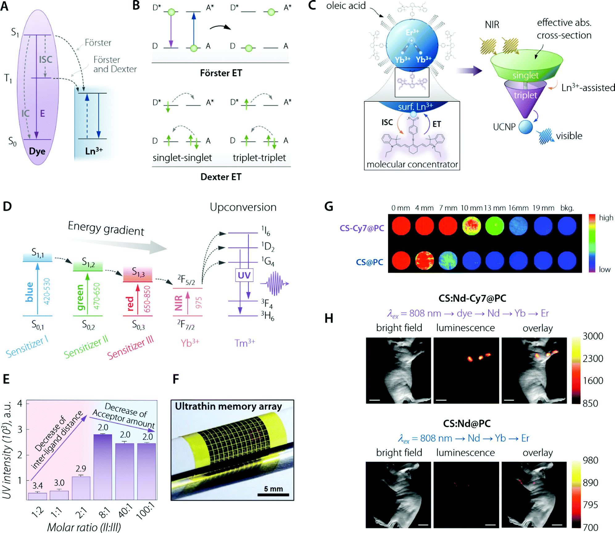 | ||
Fig. 4 Organic (dye) antenna. (A) Schematic of the energy transfer mechanisms, Förster and Dexter. (B) Schematic illustration of non-radiative energy transfer processes from the dye to Ln3+. E, IC, and ISC represent the luminescence emission, internal conversion, and intersystem crossing, respectively. Adapted with permission from ref. 89. Copyright 2017 Royal Society of Chemistry. (C) (top left) Cartoon schematic of the dye-sensitized UCNP system, showing IR-806 bound to the UCNP surface (not to scale), and an upconversion event inside the UCNP where two excited Yb3+ non-radiatively and sequentially excite Er3+ into a higher energy state. (bottom left) Magnified illustration of the interactions between IR-806 and a surface lanthanide—the heavy nucleus of the lanthanide aids in ISC from IR-806 S1 → T1 states, allowing much more efficient T1 sensitization of the Ln3+ ions within the UCNP. (right) Depiction of the antenna-like nature of IR-806 in sensitizing the UCNP, conveying the much larger absorption cross-section of IR-806 relative to the UCNP, as well as S1 → T1 ISC enhancement by Ln3+. Adapted with permission from ref. 86. Copyright 2018 Springer-Nature. (D) Energy diagram of a three sensitizer-system and ions of the so-sensitized UCNPs. The thick horizontal lines represent the energy levels and the arrows represent the sequential energy transfer. (E) Upconverted UV emission intensity from the double-ligand UCNPs (1.6 mg mL−1). Molar ratios of sensitizer II and III range from 1![[thin space (1/6-em)]](https://www.rsc.org/images/entities/char_2009.gif) :2 to 100:1. The 517 nm laser power density is 25 mW mm−2. The number written above the purple bars indicates the calculated interligand distances (nm). Overall, the figure shows that there is a trade-off (appreciable in terms of final UV emitted intensity) between the increasing number of sensitizer ligands and the relative decrease in the acceptor amount. That is, the former effect is beneficial for absorption of the excitation beam while the latter decreases the effective transfer of optical energy to Tm3+ ions. (F) Image of the integrated device array on a flexible plastic substrate. (F, G, and H) are adapted with permission from ref. 90. Copyright 2017 Wiley. (G) NIR imaging of CS & Cy7@PC and CS@PC through the pork tissue of varied thickness (excited at 800 nm). Adapted with permission from ref. 91. Copyright 2018 Royal Society of Chemistry. (H) UC luminescence lymphatic imaging at 30 min post injection of (upper) CS:Nd-Cy7@PC and (bottom) CS:Nd@PC under irradiation at 808 nm (λUCLumin = 540 ± 12 nm, scale bar = 10 mm). Adapted with permission from ref. 92. Copyright 2016 Royal Society of Chemistry. :2 to 100:1. The 517 nm laser power density is 25 mW mm−2. The number written above the purple bars indicates the calculated interligand distances (nm). Overall, the figure shows that there is a trade-off (appreciable in terms of final UV emitted intensity) between the increasing number of sensitizer ligands and the relative decrease in the acceptor amount. That is, the former effect is beneficial for absorption of the excitation beam while the latter decreases the effective transfer of optical energy to Tm3+ ions. (F) Image of the integrated device array on a flexible plastic substrate. (F, G, and H) are adapted with permission from ref. 90. Copyright 2017 Wiley. (G) NIR imaging of CS & Cy7@PC and CS@PC through the pork tissue of varied thickness (excited at 800 nm). Adapted with permission from ref. 91. Copyright 2018 Royal Society of Chemistry. (H) UC luminescence lymphatic imaging at 30 min post injection of (upper) CS:Nd-Cy7@PC and (bottom) CS:Nd@PC under irradiation at 808 nm (λUCLumin = 540 ± 12 nm, scale bar = 10 mm). Adapted with permission from ref. 92. Copyright 2016 Royal Society of Chemistry. | ||
– Non-radiative internal conversion (IC) at the dye molecule.
– Intersystem crossing (ISC) between singlet and triplet state of such molecules.
– Fluorescence emission (E).
– Energy transfer (ET) from the dye molecule acting as a donor to Ln3+ (mostly on the surface of the LNP) as an acceptor. It involves the relaxation of dye molecules to the ground state, together with the promotion of Ln3+ to their excited state.
Zooming into a more detailed description of the fourth step, it typically proceeds through either Förster or Dexter non-radiative energy transfer or a combination of the two.
For a given donor–acceptor pair (Fig. 4B), (i) the Dexter mechanism is an exchange interaction, which involves double electron transfer and requires a sizeable orbital overlap between the wavefunctions of organic molecules as the donor (D) and the Ln3+ as the acceptor (A); (ii) Förster (or dipole–dipole) mechanism is an electrostatic interaction, in which the dipole moment associated with the dye molecule's state couples with the dipole moment of the 4f orbitals. In addition, dipole–multipole transfers play a non-negligible role in the sensitization of Ln3+ ions.84,85
Both singlet and triplet states of the organic molecules may transfer energy to the lanthanide ion, possibly with the assistance of phonons. However, since the singlet state is short-lived, transfer from this latter level is often not efficient. The most likely energy transfer process to happen (ET from S1; Fig. 4A) leads as its outcome to the relaxation of dye molecules to the ground state S0 and promotion of Ln3+ to an excited state. But it is also possible that ISC (whose likeliness is inversely proportional to the S1–T1 energy gap) can occur more efficiently than the ET from S1 just described. If that is the case, the dye molecule will first switch to its triplet state (T1), then an ET from T1 to Ln3+ may happen. This second kind (and less likely to occur) ET can be Förster, Dexter, or both simultaneously. In a majority of the published dye–Ln3+ systems, emphasis has been put on Förster-based description only because of the higher ET rate from S1 over the ISC one. Inter-distance wise, at an estimated dye molecule–Ln3+ distance in the 1–2 nm range, Dexter ET was usually found to be negligible or, at maximum, comparable with the Förster mechanism.
Albeit a selected list of representative applications and developments of the organic antenna approach for the enhancement of LNPs absorption is included within this section (Table 2), we decided to highlight here the innovative work by D. J. Garfield et al.86 Therein, the authors managed to amplify UC nanoparticles’ (UCNPs) emission by enriching the molecular antenna triplets. This was accomplished by promoting the ISC in the dye via the adjustment of the UCNP composition. It was demonstrated that the triplet states in the dye antennas critically affect the brightness and stability of the dye–UCNP systems, thus providing relevant insight to overcome limitations found in previously reported materials. The IR-806-sensitized NaYF4:Yb3+,Er3+ UCNPs underwent an adjustment of the Gd3+ content, from 0 to 30%, substituting the Y3+ ions. In particular, ISC within the dye was found to be enhanced by the larger spin–orbit coupling to Ln3+ ions near the surface of the UCNPs achieved by increasing the Gd3+ content (Fig. 4C). Furthermore, this enriched triplet population was responsible for a significant amount of energy transfer into the UCNPs. The overall result was a 30-fold enhancement in the UC emission. The main conclusion of this work is the possibility to concurrently optimize the LNP composition and the dye sensitization pathway to achieve maximum optical performance.
| LNP | Dye molecule | Excitation wavelength (nm) | Enhancement (emission range) | Ref. |
|---|---|---|---|---|
| β-NaY3+ (78 − x)%Gd3+x%Yb3+20%Er3+20%F4 | IR-806 | 808 | 33000-fold (520 to 680 nm; Er3+ VIS emission) |
86 |
| Y3+80%Ln3+20%F4 (Ln = Nd3+ or Yb3+) | Tropolonate (Trop) | 340 | Not reported (900–1100 nm) luminescence lifetimes (longest components) >5 times longer (Yb) >11 times longer (Nd) | 93 |
| La3+95%Eu3+5%F3 | 6-Carboxy-50-methyl-2,20-bipyridine (bipyCOO−) | 305 | ∼100-fold (615 nm) | 94 |
| β-NaYF4:Yb3+,Er3+ | IR-806 | 800 | 3300-fold (720–1000 nm) | 95 |
| (NaYbF4:Tm3+ 0.5%)/NaYF4:Nd3+ | IR-808 | 800 | 14-fold (300–700 nm; Tm3+ UC range) | 96 |
| NaYF4:Tm3+,Yb/NaYF4:Yb3+ | IR-1061 | 980 | 2.8-fold (800 nm) | 97 |
| NaYF4:Yb10%,Er2%/NaYF4: Nd 30% | IR-783 | 670–860 | Not reported (300–700 nm) | 98 |
| NaYF4:Yb3+,X/NaYbF4/NaYF4:Nd3+ (X = null, Er3+, Ho3+, Tm3+, or Pr) | Indocyanine green (ICG) | 700–860 | 4-fold (multipeak between 1000–1600 nm) | 99 |
| β-NaYF4:Yb20%, Tm 0.5% | I: BODIPY-FL | 488, 517, 800, and 980 | Between 50 and 100-fold (340–360 nm) | 90 |
| II: Cy3.5 | ||||
| III: IR806 | ||||
| NaYbF4/NaYF4:Nd3+ | Cy7 | 808 | 15-fold (980 nm) | 91 |
| NaYF4:Yb3+,Nd3+,Er3+/NaYF4:Nd3+ | Sulfonic-functionalized Cy7 | 808 | 17-fold (520 to 680 nm; Er3+ VIS emission) | 92 |
By 2007, the first report was published by J. Zhang et al. for testing the concept of an organic dye acting as the antenna for lanthanide-doped (inorganic) nanoparticles.93 This seminary paper portrayed the combination of the antenna effect provided by organic chromophores with the protection of Ln3+ given by an inorganic matrix. At the dawn of using antenna dyes for LNPs, the work from L. J. Charbonnière et al. must be highlighted.94 The authors reported an increase in the emission of Eu3+ under 305 nm excitation of up to two orders of magnitude, as compared to the same Eu3+-doped nanoparticles with no dye attached. A thorough photo-physical study demonstrated that such a large increase in the brightness of the LNP's luminescence, with a corresponding long-lived excited-state lifetime, was caused by a broad absorption in the near-UV and subsequent energy transfer to Eu3+ from bipyCOO− ligands tethered to the surface.
A remarkable milestone of this bubbling trend was published in 2012, when W. Zou et al. reported an enhancement by a factor of ∼3300 of the overall sensitized UC emission of NaYF4:Yb3+,Er3+ UCNPs by using the NIR-absorbing IR-806 organic dye as the antenna.95 This dye was a carboxylic acid-functionalized derivative created by the nucleophilic substitution of the central chlorine atom in IR-780, which is a commercially available cyanine dye. The use of such a novel dye resulted in a blue-shift (806 nm) in the absorption maximum of the structure (LNP + dye) from 975 nm (i.e., direct Yb3+ absorption) that is otherwise used for the optical excitation of the very same LNPs with no dye attached. The extinction coefficient of IR-806 at 806 nm was measured to be ∼5 × 10⁶ times higher than that of NaYF4:Yb3+,Er3+ nanoparticles at 975 nm. Interestingly, a set of photophysical control experiments demonstrated that ∼50% of the photon energy initially absorbed by IR-806 is transferred to the Yb3+ and Er3+ energy-accepting ions in the NaYF4:Yb3+,Er3+ core. The glaring shortcoming of the proposed system was the remarkably large energy gap between the energy levels of the dye molecule and the Yb3+ ion. This fact limited the ET efficiency to support the UC process via the usual ET pathway (dye to Yb3+ and then to the Er3+ emitter). Moreover, the energy mismatch between the dye–Yb3+ energy levels may cause the ET performance to be undesirably temperature-dependent. Years later, G. Chen et al. introduced the concept of cascade energy UC to mitigate such a drawback. Using NaYbF4:Tm3+0.5%/NaYF4:Nd3+ core/(active) shell UCNPs sensitized by different NIR-absorbing dyes as a model, they achieved a large enhancement in visible UC emission, efficacious ET, and surprisingly high (∼19%) PLQY.96
As outstanding example from the materials viewpoint, in 2018, the work by C. Hazra et al. pushed the limits on the spectral range of excitation wavelength for dye-sensitized UCNPs.97 In that work, the use of a water-dispersible dye absorbing above 1000 nm (IR-1061) to sensitize NaYF4:Yb3+30%/Tm3+0.5%/NaYF4:Yb3+10% core/active shell UCNPs was proposed for the first time. Having the goal of proofing biomedical potential, the authors managed to encapsulate the as-synthesized NIR-absorbing dye in the polyoxomer Pluronic F68 (PF-68), thus rendering the dye water dispersible owing to the presence of hydroxyl groups. From a quantitative standpoint, a relatively modest ∼3-fold enhancement in the 800 nm emission of the Tm3+ ion was reported from such IR-1061-sensitized UCNPs via the doping of Yb3+ ions (10% optimal) in the UCNP shell (i.e., core/active shell architecture). Critically speaking, the performed excitation at 980 nm did not allow to fully profit from the IR-1061 absorption, which peaks at longer wavelengths within NIR-II. Moreover, the experiments also carried the drawbacks of a relatively strong water absorption at the chosen excitation wavelength.
In the ever-growing field of integrated photo-electronics, systems based on dye-sensitized LNPs have also been actively developed. The work by J. Lee et al. is remarkable for several reasons,90 starting from the use of a multi-dye organic antenna to sensitize the β-NaYF4:20%Yb3+,0.5%Tm3+ UCNPs. The three dyes were, namely, BODIPY-FL, Cy3.5, and IR-806, having in common their composition, comprising an energy harvesting aromatic fluorophore and a carboxylic acid for linkage to the UCNP. This game-changer approach widens the photon absorption window of such nanoparticles, from solely the NIR range (975 nm, when relying on just Yb3+ as the sensitizer) to the entire visible and NIR-I range (450–975 nm) (Fig. 4D). Such an expansion of the excitation range, encompassing photons that cannot be used in conventional UCNPs, maximized the utility of such Yb3+,Tm3+-doped UCNPs. This is because a large photo-absorption bandwidth with high absorption coefficients increases the upconverted output emission intensity in the UV range. Moreover, the authors walked the extra mile in terms of material engineering, optimizing the sensitizer-ligand distance and the ratio between the different organic dyes, thus further increasing the efficiency of the sequential ET and UC processes (Fig. 4E). Finally, the third exciting aspect of the work lies in the application of such a fine-tuned nanosystem, in collaboration with ultraviolet (UV)-responsive photo-acid-generators (PAGs), as a new information security module in data storage devices with the function of unrecoverable data erasure. Because of the ultrathin nature of the so-built electronics, the entire system is deformable and can be integrated on various curvilinear surfaces including the human skin (Fig. 4F).
Not all the outstanding examples of organic antennas that improve absorption for LNPs have been developed for UC systems (Table 2). The current growing trend of developing NIR emitters for biomedical imaging owing to the deeper penetration, better optical contrast, and low tissue autofluorescence characterizing such spectral “transparency window” finds a fertile ground in LNPs. NaYbF4/NaYF4:Nd3+60% nanoparticles were coupled with high-PLQY Cy7 dye in the work by Q. Liu et al. in 2018.91 Starting from a pure NaYbF4 emitter core, the authors augmented the Nd3+ doping concentration up to 60% in the outer shell, which is appreciably higher than in the case of most reported dye-sensitized systems. The architecture favoured the optically-absorbed energy that is transferred from the sensitizer (Cy7) to the emitters (Yb3+) via intermediate ions (Nd3+), the overall benefit being offered by a significant increase in the absorbance of the LNPs. Therefore, the brightness was increased, yielding a deeper imaging penetration (Fig. 4G). The relevance of this report lies also in how the water-solubility and biocompatibility of the nanosystem were addressed by wrapping the Cy7 dye–core/shell composite in phosphatidylcholine. This way, two of the key points of concern for biomedically-oriented LNPs were taken care of. This NIR-emitting (centred at 980 nm) material was applied in vivo, proving itself to be a promising imaging agent for fluorescence-guided surgery by way of its application in assisting in the procedure of peritumoral lymph node dissection. Notwithstanding the achievements of this paper, in line with the critical approach of this review, it is also worth noting that the characterization performed by the authors showed that coating with an inert shell would make energy transfer efficiency from Cy7 to Nd3+ relatively weak. This happens because the undoped outer shell increases the physical distance between the (donor) organic molecules and the (acceptor) Ln3+ ions, thus hindering ET between the two species. Such incompatibility of the approaches severely limits the possibility to simultaneously implement organic antennas (for absorption betterment) together with the growth of an undoped outer protective shell (nowadays, a widely used method to improve the LNPs’ quantum yield). This constitutes a limiting issue within the framework of LNPs’ achievable brightness by the use of organic antennas, a matter discussed further in this review (vide infra).
Highlighting the most promising NIR-absorbing organic dyes, the above mentioned Cy7 has indeed made possible in vivo imaging even for UCNPs acting as imaging probes by emitting in the visible range. This result is remarkable, considering the sizeably lower tissue penetration depth in that wavelength range. Indeed, Nd3+-based UCNPs sensitized with Cy7 demonstrated, as shown in the report by X. Zou et al., in vivo lymphatic imaging at 540 nm under excitation at 808 nm (Fig. 4H).92
Finally, the report from W. Shao et al. in 2016 should also be analyzed within the current research trend to develop downshifting LNPs for in vivo imaging, which emit at longer wavelengths (NIR-II and NIR-III spectral ranges, meaning 1000–1700 nm).99 Therein, upon achieving NIR-II, III emission, the authors aimed at profiting from the assets already described above that arise from shifting the signal collection towards longer wavelengths (i.e., deeper sub-skin penetration, better optical contrast, and higher signal-to-noise ratio). Thus, the NaYF4:Yb3+/X3+/NaYbF4/NaYF4:Nd3+, (X = null, Er, Ho, Tm, or Pr) core/shell/shell system, with indocyanine green (ICG) attached to the LNP surface, was designed to create a cascade ET pathway upon 700–860 nm optical excitation: ICG → Nd3+ (outer shell) → Yb3+ (inner shell) → Yb3+/X3+ (core). The ICG antenna not only enhanced the overall brightness of the multiple-line emission of the LNPs by ∼4 times but also provided the much broader excitation band than the LNPs had just by themselves. The proof-of-concept of NIR-II, III bioimaging was extended in vivo by means of subcutaneous injection of an aqueous suspension of phospholipid-encapsulated ICG-sensitized core/shell/shell LNPs, which allowed imaging in a mouse.
3.3. Semiconductors as light harvesters
The use of SCNs for the sensitization of Ln3+ emission follows the same principle of organic antennas: the semiconductor moiety should be able to absorb the optical energy and transfer it to the Ln3+ ions. The pivotal difference from the case of organic antennas is that the role of the dye's singlet/triplet states is herein played by the semiconductor's excited states. These can be localized excitonic levels, inter-bandgap levels, and charge trap states (Fig. 5A). SNCs have a molar absorption coefficient that is generally slightly larger than that of the dyes (up to 106vs. up to 105 M−1 cm−1).100 However, the smaller size of dye molecules could mitigate this partial shortcoming since it is plausible to think that more dye molecules than SNCs could be accommodated on the surface of the LNPs (if the decoration LNPs with SNCs is the pursued approach). On the other hand, in the case of using SNCs, the final material is fully inorganic and hence, it is less prone to photobleaching and degradation in harsher environments.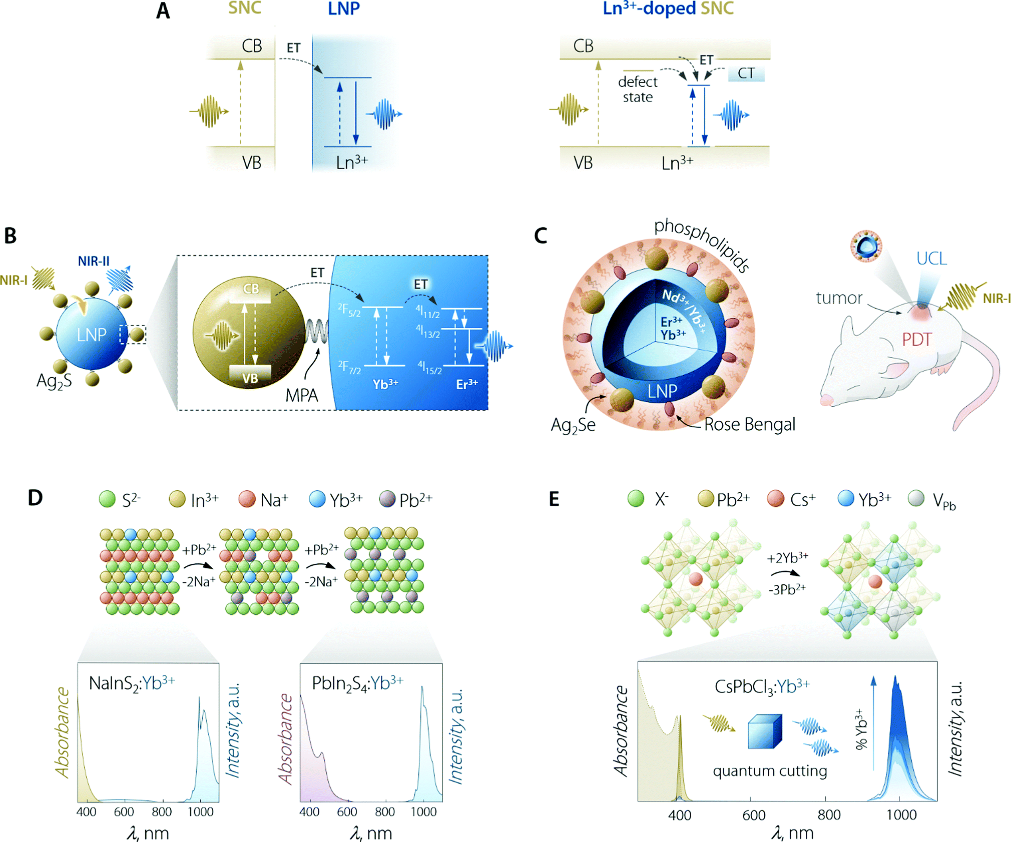 | ||
| Fig. 5 Use of SNCs to increase the brightness of lanthanide emission. (A) Partial energy level diagrams to illustrate the sensitization mechanism between conjugated SNC and LNP moieties (left) and in the case of Ln3+-doped SNC (right). In the latter case, CT means charge transfer state; dark yellow arrows indicate the ET processes and vertical lines are the electronic transitions. (B) Scheme of Ag2S SNC-decorated Yb3+,Er3+-doped LNPs along with the proposed energy transfer mechanism responsible for the sensitization of lanthanide NIR emission. MPA = 3-mercaptopropionic acid. Adapted with permission from ref. 101. Copyright 2020 American Chemical Society. (C) Scheme and means of operation as an optical probe and PDT agent of the Ag2Se–LNP–Rose Bengal composite encapsulated in phospholipids. Adapted with permission from ref. 102. Copyright 2019 American Chemical Society. (D) Preparation of Yb3+-doped PbIn2S4 SNCs and their optical properties. The cation exchange process to transform NaInS2 into PbIn2S4 entails the substitution of two Pb2+ ions for each Na+. Both NaInS2:Yb3+ and PbIn2S4:Yb3+ feature host-sensitized Yb3+ emission around 1000 nm; however, upon passing from NaInS2 to PbIn2S4, the absorption extends to longer wavelength, covering a good part of the visible spectrum. Adapted with permission from ref. 103. Copyright 2017 American Chemical Society. (E) Lanthanide doping scheme in Pb2+-based halide perovskite SNCs along with the absorption and emission spectra of CsPbCl3:Yb3+ SNCs doped with increasing amounts of lanthanide ion (from 0 to 7.4%). Adapted with permission from ref. 104. Copyright 2018 American Chemical Society. | ||
Aside from the points above, a fair comparison should also include the efficiency of transfer between the light harvesting moiety (dye or SNC) and the lanthanide ion. Unfortunately, the very limited availability of these numbers makes it difficult to fairly compare the performance of the two approaches from this point of view.
The sensitization of Ln3+ through SNCs was accomplished via different approaches, such as the coupling of SNCs and LNPs, doping of Ln3+ in a SNC, and the synthesis of core/shell SNC/LNP structures (Table 3). Albeit these methods rely on a similar operation principle (Fig. 5A), they require attention to different variables.
| Ln3+-Doped SNCs | ||||
|---|---|---|---|---|
| Ln3+ | Semiconductor | Excitation range (nm) | PLQY | Ref. |
| Eu3+ | CdS | <400 | — | 113 |
| Tb3+ | CdSe | <500 | 0.03% | 114 |
| Yb3+ | CdSe | <600 | — | 115 |
| Tb3+, Eu3+ | ZnS, ZnSe, CdSe | ZnS: <410 | ZnS:Tb3+: 12% (overall), 5% (Tb3+) | 116 |
| ZnS:Eu3+: 27% (overall), 0.01% (Eu3+) | ||||
| Tb3+ | ZnO | <420 | — | 143 |
| Eu3+, Er3+, Sm3+ | TiO2 | 488 | — | 144 |
| Eu3+ | In2O3 | <400 | — | 120 |
| Eu3+, Tb3+ | Ga2O3 | <250 | Eu3+: 0.1% | 121 |
| Yb3+ | NaInS2, PbIn2S4 (CdIn2S4, AgInS2) | <600 | 5% (λex = 405 nm) | 103 |
| (Er3+–Ce3+, Nd3+–Ce3+) | CaS | <300 (host), 400–500 (Ce3+) | Er3+: 9.3%. Nd3+: 7.7% [excited through Ce3+] | 122 |
| Yb3+ | CsPbCl3 | <410 | Up to 170% (λex = 380 nm) | 104 |
| Ce3+, Sm3+, Eu3+, Tb3+, Dy3+, Dy3+, Er3+, Yb3+ | CsPbCl3 | <410 | Yb3+: 142.7% | 128 |
| Eu3+: 27.2% | ||||
| Yb3+–Pr3+–Ce3+ | CsPbClBr2 | <480 | 173% (overall) | 129 |
| Yb3+, Er3+ | Cs2AgInCl6 | <300 | Yb3+: 3.6% | 134 |
| Er3+: 0.05% | ||||
| Yb3+ | Cs2AgBiCl6 | <420 | <1% | 135 |
| Cs2AgBiBr6 | <520 | |||
| Eu3+ | Cs3Bi2Br3 | <425 | 42.4% (overall), approx. 28% (Eu3+) | 136 |
| Other structures | ||||
|---|---|---|---|---|
| Ln3+-Doped material | Semiconductor | Excitation wavelength (nm) | PLQY | Ref. |
| YF3:Yb3+/LuF3 (shell material) | InP (core material) | 440 (and 760) | 0.1–0.5% | 142 |
Nonetheless, as mentioned above, one of the main disadvantages of this approach lies in the necessity of the SNCs to be in close proximity to the sensitizer ions for the ET to effectively take place. This means that only superficial ions in the LNP can accept energy from the SNCs. This reduces the possibility of growing a passivating shell on the LNPs, as also underscored earlier in this minireview in the case of dye-sensitization of LNP emission (see Section 3.2.3). All these considerations have also been demonstrated in the reverse case of LNP-to-SNC ET105,106 and they pose limitations in the design of the final nanostructure.
Early attempts to prepare Ln3+-doped SNCs focused on the use of binary semiconductors, such as CdS,113 CdSe,114,115 and ZnS.116 However, these lattices are far from ideal in this context since therein Cd2+ and Zn2+ occupy low-CN sites (tetrahedral). Moreover, these ions feature different size and oxidation state compared to Ln3+. In fact, most of the works attempting Ln3+ incorporation in the SNC lattice mainly report the evidence of surface absorption of the dopant ions.117 Some success was obtained by the group of Meijerink, who managed to immobilize Yb3+ ions on the surface of the CdSe SNCs via ion adsorption, followed by the overgrowth of a thin Se layer.115 Numerous studies have been reported on the incorporation of Ln3+ in oxide-based semiconductor nanoparticles, such as ZnO,118 TiO2,119 In2O3,120 and Ga2O3.121 Although host sensitization is achieved in these materials, the efficiency is generally poor and the absorption of the semiconductor moiety lies in the UV-vis part of the spectrum. Interestingly, Gamelin and co-workers reported the incorporation of Ln3+ in the lattice of colloidal ternary SNCs (Fig. 5D).103 Their approach involved the use of NaInS2 as the host material—a ternary semiconductor where In3+ resides in an octahedral environment. The similar ionic radius of this cation compared to Ln3+, along with same oxidation state (3+), allowed for the effective incorporation of Yb3+ in the lattice. The advantage of using a ternary system where cations with different properties (i.e., Na+ and In3+) granted the possibility to perform selective cation exchange to fine-tune the optical properties of the Ln3+-doped SNCs. The authors showed that Na+ can be substituted by Cd2+, Ag+, and Pb2+. Exchange with the latter cation afforded partially-exchanged PbIn2S4:Yb3+ SNCs, which exhibited extended visible absorption and a maximum PLQY of 5%.
Other host materials that grant effective Ln3+ doping are alkaline-earth semiconductors (AESs) such as CaS and SrS.109,122–124 The large cationic radius of the alkaline earths, along with their high CN, allows for their substitution by lanthanides. Often, Ce3+ is doped in these hosts, while europium takes its divalent state. Hence, albeit host sensitization is observed, efficient direct excitation of doped lanthanide ions is generally realized. For instance, Zhang et al. recently prepared CaS:Ce3+,Er3+ and CaS:Ce3+,Nd3+ featuring NIR emission under UV-blue excitation. Energy transfer from Ce3+ to the second Ln3+ enabled bright emission (PLQY of 9.3 and 7.7%, respectively, for Er3+ and Nd3+). After transferring these LNPs to water with the aid of phospholipids, the authors managed to sense H2O2 and H2O2-producing disease marker xanthine in water. The detection of these species was afforded by the quenching of Ln3+ emission in the presence of hydrogen peroxide.
This section would not be complete without mentioning halide perovskites. In the past few years, semiconductors of the family CsPbX3 (where X = Cl, Br, I) have become the staple for Ln3+ doping in SNCs, with unmatched results in terms of host-sensitized photoluminescence efficiency.108 Halide perovskites, in general, feature octahedral sites, which offer an ideal coordination environment for Ln3+. In lead-based systems, doping with Ln3+ proceeds through the substitution of three Pb2+ for every two incorporated lanthanides.104,125 To maintain the charge balance, a Pb2+ vacancy (VPb) is also introduced. The most energetically-favourable configuration of the resulting defect complex (Ln3+–VPb–Ln3+) is shown in Fig. 5E. Hence, Ln3+ doping of halide perovskites proceeds through the creation of defects and the possibility to successfully dope this material hinges on the tolerance that it possesses towards defects, both structure- and emission-wise.126,127 Several Ln3+ (Ce3+, Sm3+, Eu3+, Tb3+, Dy3+, Dy3+, Er3+, Yb3+) were doped in CsPbCl3 SNCs by Pan et al.,128 observing increased overall PLQY (exciton + Ln3+ emission) compared to the undoped system. Stunningly, the PLQY in the case of Yb3+ doping overcame 100%. Because of their high conversion efficiency and the ideal overlap of Yb3+ emission with silicon absorption, Yb3+-doped halide perovskites are thus envisioned as ideal conversion materials in photovoltaic devices. Indeed, conversion layers for silicon and Cu(In,Ga)(S,Se)2 cells129,130 and quantum cutting luminescent solar concentrators (QC-LSC) have been prepared using Ln3+-doped lead halide perovskite SNCs. This quantum cutting phenomenon was further investigated by Milstein et al., who described it with the help of low-temperature photoluminescence study on La3+-doped SNCs.104 The authors explained quantum cutting as assisted by shallow defect states below the conduction band, thus effectively bridging the electronic states of the SNC and the Ln3+. In a following study, Li et al. modelled this quantum cutting phenomenon and explained it in light of the higher density of states (DOS) at the CB edge featured by Pb2+ located close to the Yb3+ ions. This increased DOS favours strong localized absorption in correspondence of the transition metal ion, followed by energy transfer to the two nearby Yb3+.125 Ln3+-doped lead-based perovskite SNCs were also used for preparing with-light emitting diodes, wherein blue-emitting GaN chips were coated with polymeric dispersions of, for e.g., CsPbCl3:Ce3+,Eu3+ (ref. 128) or CsPbCl1.8Br1.2:Ce3+,Mn2+.131 Despite Pb2+-based halide perovskites’ showcasing excellent luminescent performance, the presence of lead in their composition, in hand with the poor chemical resistance towards moisture, poses major concerns in terms of the toxicity and environmental impact.132 Ln3+-doping has been shown to improve the stability of CsPbX3133 but their foreseeable applicability remains limited mainly to water-free environments. In search for more sustainable alternatives, the incorporation of Ln3+ in other lead-free mixed perovskites has been performed too, using hosts such as halide double perovskites (e.g., Cs2AgInCl6134 and Cs2AgBiCl6135) and Cs3Bi2Br3.136,137 To this end, Eu3+-doped SNCs of the latter material have been prepared by Ding et al., who employed them in aqueous media for Cu2+ detection, a rare instance of the use of perovskites in water.136 However, the emission efficiency of Pb2+-free systems is often lower compared to the one featured by lead-containing ones. Lastly, the absorption of halide perovskites generally cannot be effectively tuned towards the red-NIR part of the spectrum, thus further limiting the versatility in terms of the working wavelength range, particularly foreseeing applications in the biomedical field where NIR working capabilities (both absorption and emission) are key.
Despite the challenges of doping Ln3+ in SNCs, an additional advantage of this avenue is the possibility of exploiting the host-to-metal charge transfer (CT) phenomena to sensitize the activator luminescence.138,139 According to the model proposed by Dorenbos140 (and validated several times experimentally), Ln3+ ions that are more likely to give rise to CT are Eu3+ and Yb3+, followed by Sm3+ and Tm3+. This is because of the lower-lying ground state of their divalent form (Ln2+) compared to other lanthanides. This subject is rather complex and its thorough explanation lies beyond the scope of the present review. The interested reader is redirected to the body of work from Dorenbos (see, for example, ref. 141). The important aspect to consider is that when Ln3+ ions are doped in hosts composed of relatively polarizable anions (such as S2− and Se2− as opposed to O2− and F−), absorption corresponding to the CT band occurs at lower energies. This observation opens the door to the possibility of tuning the position of CT-related light absorption by controlling the host composition.
Lastly, this approach for combining Ln3+ and SNCs allows for core/shell architectures to be prepared. The passivation of the surface therefore becomes possible, aiming for higher PLQY. We foresee exciting scenarios ahead in this avenue.
4. Conclusion and perspective
In this minireview, we have assessed the state-of-the-art of three families of approaches to improve the brightness (mainly by increasing the absorption capability) of lanthanide-doped nanoparticles. These strategies entail the use of (i) plasmonic species, (ii) organic antennas, and (iii) semiconductor nanocrystals. From our critical literature survey, we can draw several general conclusions:– The interest around the production of brightly-emitting nanoparticles based on lanthanide ions is vivid. Efforts towards this direction are driven by the possibility of broadening the applicability of these unique luminescent species in fields such as lighting, photovoltaics, and bioimaging.
– Enhancement of the light absorption properties of lanthanide ions appears to be the decisive step in undertaking the pursuit of increased emission brightness of these species. Strategies to achieve this goal are constantly being honed both from a physical and chemical standpoint. A better understanding of the mechanisms involved in brightness enhancement by way of absorption enhancement allows for a more rational and effective design of the material. On the other hand, new materials and synthetic strategies are being proposed, thus opening a host of new opportunities.
– Despite the advancements witnessed in the preparation of more intensely-emitting lanthanide-based nanoparticles, we are far from the performance and reliability of other luminescent species, such as fluorescent small molecules, quantum dots, or even lanthanide complexes. Yet, it is encouraging to observe that dye-sensitized lanthanide-based nanoparticles have been applied with unrivalled results in cellular imaging thanks to improved brightness and sensitivity compared to other fluorophores.145,146 However, in general, there is plenty of room for improvement in terms of brightness enhancement as well as chemical and photostability.
Regarding the specific strategies discussed in this review, the following conclusions have been reached.
– Coupling with plasmonic materials is one of the most exploited approaches to enhance the emission intensity of lanthanide-based nanoparticles. Yet, in colloidal systems, the degree of control that can be exerted over the reciprocal position of the two moieties is limited. The combination of wet-chemistry methods and metal deposition has already proven to be a useful hybrid approach for the preparation of unique architectures. In these nanosystems, the electromagnetic field is concentrated within the lanthanide-doped nanoparticle, thus allowing for maximum luminescence enhancement. It is expected that similar results can be achieved harnessing methods to decorate selectively different sites of plasmonic nanostructures.147 Lanthanide-doped materials can be deposited, for instance, at the tip of the gold nanorods, where the longitudinal plasmonic mode results in maximal localized enhancement of the electromagnetic field. On top of that, the use of plasmonic materials other than noble metals should be further investigated. For example, materials with plasmonic resonance located deeper in the NIR (e.g., >1400 nm) could be used to enhance the absorption and/or emission of lanthanide ions at these wavelengths, which are relatively unexplored. Copper chalcogenides, indium tin oxide, and LaB6 nanoparticles could serve that purpose. We also observed a lack of studies where the lanthanide-doped moiety is optimized in terms of the dopant type, concentration, and relative positioning. The mastery achieved in preparing complex structures with multiple shells, wherein different dopants are spatially segregated for maximum optical performance, has grown in the past few years.148,149 Therefore, it should be employed also in the design of nanomaterials with even brighter plasmon-enhanced luminescence. We also note that the body of literature dealing with brightness enhancement of LNPs by betterment of the absorption capabilities of Ln3+ is limited. This is unfortunate since this approach is the one anticipated to yield higher enhancements and thus, more efforts should be put in this direction. One of the possible battlefields where nanostructures based on LNPs and PNPs could be deployed is biomedicine for theranostic (therapeutic + diagnostic) purposes. Enhanced upconversion luminescence and downshifting emission can be harnessed to photoinitiate chemical reactions in situ and imaging, respectively. However, the presence of the plasmonic part could be a double-edged sword owing to its light-to-heat conversion capability; if, on the one hand, this effect can be harnessed for photothermal therapy, on the other hand, unwanted and uncontrolled heating can be generated upon irradiation.
– The most pressing shortcomings toward the consolidation of the use of organic antennas for addressing the low absorption of LNPs are basically three. Firstly, opting for this approach (absorption enhancement) limits the possibility to prepare nanoparticle architectures with an undoped outer shell, which is known to lead to an improvement of the quantum yield through quenching suppression. The undoped shell both alleviates the quenching phenomena, arising from surface defects as well as from the interaction between Ln3+ and solvent molecules with vibrational modes resonant with Ln3+ transitions. However, the distance imposed by the shell between the Ln3+ and the surface, where organic molecules anchor makes the antenna approach poorly effective, as successful energy transfer requires the involved species to be at close range. A possible solution to this conundrum could surge from the use of an optically-active organic polymer able to act as the antenna for Ln3+, simultaneously providing strong isolation to the very same Ln3+ from the vibrational modes of solvent (water) molecules.
The second limitation is directly related to the structural stability and long-term robustness of the whole antenna-nanoparticle construct. In a majority of the published reports, the binding stability of the dye onto the nanoparticle surface remains largely a matter pending further study, along with the unknown photostability of the dye-sensitized LNP. To that end, no comparative studies have been systematically performed for the most functional “anchoring” methods, i.e., covalent bonding, electrostatic attraction, and physical absorption. In particular, the unknown stability of the bond between the dye and the nanoparticle curbs the application of these nanocomposites in the in vivo biomedical arena. Indeed, upon injection in the specimen, these LNPs would find themselves in a potentially aggressive environment that could possibly induce detachment of the dye molecules.
Lastly, the third relevant factor imposing constraints is the number of dyes per nanoparticle. In the published works, this number has often been reported to be less than 1000:1, thus posing a threshold to the light-harvesting ability of dye-sensitized LNPs. In other words, there seems to exist an upper limit of dye molecules per nanoparticle, above which the molecules are more likely to transfer energy between them than to the Ln3+ inside the LNP matrix.
As a general comment, there is still a sort of “thematic-scope gulf”, keeping disciplines away between researchers working on the physical properties of lanthanide ions (particularly, the luminescence side of LNPS) and organic chemists, in particular, those interested in the soft-chemistry facet of colloidal dispersions. However, it is reasonable to think that this gap will continue to be gradually bridged, especially when considering previous relevant cases such as the very travelled research road of dye-sensitized semiconductor solar cells.
– The research line dealing with the use of semiconductor materials to sensitize the emission of lanthanide ions is by far the one that is gaining greater momentum thanks to the advent on the scene of halide perovskites. The optical and structural properties of these materials make them utterly suitable for the preparation of Ln3+-doped nanoparticles with bright emission. Provided that lead-based species are the ones performing the best, future effort should be put in the development of LNPs based on heavy metal-free materials that are also resistant to moisture (hence more broadly applicable in aqueous environments). Bismuth-based and halide double perovskites are amongst the most promising materials in these regards. Following this path, on the one hand, concerns about the toxicity of the material would be mitigated. On the other, more stable and water-resistant species will ensure their broader applicability in field such as light-emitting diodes, photovoltaics, and biomedicine. Aside from perovskites, it is foreseeable that novel, efficient lanthanide-doped semiconductor nanocrystals could be produced, leveraging the strategy of ion exchange, following the example set by the group of Gamelin.103 Ternary semiconductors represent the ideal canvas for this approach as they allow orthogonal manipulation of their composition (i.e., selective exchange of one or the other metal ion). Once these strategies will be mastered, taking one page from the book of quantum dots, the preparation of core/shell architectures is the natural successive step. The minimization of surface quenching phenomena that will result is envisaged to increase the emission brightness of doped lanthanides to an even higher degree. Core/shell structures, where the core is an LNP and the shell is constituted of semiconductor materials, are also expected to be designed (although lattice mismatch between the materials involved might pose serious limitations to the realizability of these structures). Regarding other strategies, the coupling of pre-synthesized semiconductor nanocrystals and lanthanide-doped nanoparticles could provide a means to more finely tune the optical properties of the two moieties in a separate way. On the negative side, the nature of the interparticle energy transfer mechanisms involved in the sensitization process poses limits in terms of the maximum distance between the energy donor (semiconductor nanocrystal) and the acceptors (lanthanide ions doped in the nanoparticle). Notwithstanding this, it is often easier to prepare such composite structures rather than pursuing lanthanide doping in semiconductors, given the knowledge gained over the recent years of nanoparticle surface functionalization. This knowledge also allows to agilely tune the affinity (i.e., dispersibility) of the composite towards different environments depending on the application sought after, a task more challenging in the case of using organic dyes, most of which are not hydrophilic. Consequently, we propose that the coupling of semiconductor nanocrystals and lanthanide-doped nanoparticles could bring exciting results in the next few years, particularly in the biomedical context.
All in all, the journey in the chase of brighter lanthanide-doped nanoparticles presents several opportunities and it is far from being at its end. While the avenues described above have been walked so far independently, it is also possible that they will intersect, joining forces quite literally for a brighter tomorrow. Case in point, the coupling of plasmonic nanoparticles and lanthanide-doped nanocrystals can be performed with the goal of simultaneously profiting from host sensitization and Purcell effect. The decoration of lanthanide-doped nanoparticles with both plasmonic species and organic dyes could be performed too. These are just some examples but the list of combined methods is expected to quickly become longer.
Like we have mentioned throughout Section 3, the application fields that would mainly benefit from the availability of lanthanide-doped inorganic nanoparticles are photovoltaics, lighting, sensing, and biomedicine. Of course, each area necessitates specific requirements to be met in terms of optical and physicochemical features, as well as the toxicity profile of the nanosystem. For this reason, it is plausible to think that different strategies will provide species suitable for different applications. What we are convinced of is that lanthanide-doped nanoparticles made brighter via the methods reviewed herein will play a pivotal role in several fields.
Conflicts of interest
There are no conflicts to declare.Acknowledgements
The authors thank Prof. A. Fernández-Domínguez (UAM) for helpful discussion about plasmonic concepts. R. M. is grateful to the European Commission for the financial support through the Marie Skłodowska-Curie Grant agreement no. 797945 “LANTERNS”. A. B. acknowledges funding from Comunidad Autónoma de Madrid through TALENTO grant ref. 2019-T1/IND-14014. This work was partially supported by the Ministerio de Economía y Competitividad de España (MAT2016-75362-C3-1-R), by the Ministerio de Ciencia e Innovación (PID2019-106211RB-I00), by the Instituto de Salud Carlos III (PI16/00812), and by the Comunidad Autónoma de Madrid (B2017/BMD-3867RENIMCM). Additional funding was provided by the European Union's Horizon 2020 FET Open programme under grant agreement no. 801305 (NanoTBTech).References
- M. Poliakoff, A. D. J. Makin, S. L. Y. Tang and E. Poliakoff, Nat. Chem., 2019, 11, 391–393 CrossRef CAS.
- R. Marin, G. Brunet and M. Murugesu, Angew. Chem., Int. Ed., 2019 DOI:10.1002/anie.201910299.
- D. N. Woodruff, R. E. Winpenny and R. A. Layfield, Chem. Rev., 2013, 113, 5110–5148 CrossRef CAS.
- S. F. Himmelstoss and T. Hirsch, Methods Appl. Fluoresc., 2019, 7, 022002 CrossRef CAS.
- C. D. S. Brites, S. Balabhadra and L. D. Carlos, Adv. Opt. Mater., 2018, 7, 1801239 CrossRef.
- B. del Rosal, E. Ximendes, U. Rocha and D. Jaque, Adv. Opt. Mater., 2017, 5, 1600508 CrossRef.
- A. Skripka, V. Karabanovas, G. Jarockyte, R. Marin, V. Tam, M. Cerruti, R. Rotomskis and F. Vetrone, Adv. Funct. Mater., 2019, 29, 1807105 CrossRef.
- Z. Chen, X. Wang, S. Li, S. Liu, H. Miao and S. Wu, ChemPhotoChem, 2019, 3, 1077–1083 CrossRef CAS.
- F. Vetrone, R. Naccache, A. Zamarron, A. Juarranz de la Fuente, F. Sanz-Rodriguez, L. Martinez Maestro, E. Martin Rodriguez, D. Jaque, J. Garcia Sole and J. A. Capobianco, ACS Nano, 2010, 4, 3254–3258 CrossRef CAS.
- C. D. S. Brites, B. Zhuang, M. L. Debasu, D. Ding, X. Qin, F. E. Maturi, W. W. Y. Lim, W. Soh, J. Rocha, Z. Yi, X. Liu and L. D. Carlos, J. Phys. Chem. Lett., 2020, 11, 6704–6711 CrossRef CAS.
- A. Lay, C. Siefe, S. Fischer, R. D. Mehlenbacher, F. Ke, W. L. Mao, A. P. Alivisatos, M. B. Goodman and J. A. Dionne, Nano Lett., 2018, 18, 4454–4459 CrossRef CAS.
- M. He, X. Pang, X. Liu, B. Jiang, Y. He, H. Snaith and Z. Lin, Angew. Chem., Int. Ed., 2016, 128, 4352–4356 CrossRef.
- J. Day, S. Senthilarasu and T. K. Mallick, Renewable Energy, 2019, 132, 186–205 CrossRef.
- J.-C. G. Bünzli, Coord. Chem. Rev., 2015, 293–294, 19–47 CrossRef.
- S. V. Eliseeva and J. C. Bunzli, Chem. Soc. Rev., 2010, 39, 189–227 RSC.
- O. Laporte and W. F. Meggers, J. Opt. Soc. Am., 1925, 11, 464–564 CrossRef.
- F. Auzel, Chem. Rev., 2004, 104, 139–173 CrossRef CAS.
- X. Qin, X. Liu, W. Huang, M. Bettinelli and X. Liu, Chem. Rev., 2017, 117, 4488–4527 CrossRef CAS.
- F. Wang, X. Xue and X. Liu, Angew. Chem., Int. Ed., 2008, 47, 906–909 CrossRef CAS.
- Q. Dou and Y. Zhang, Langmuir, 2011, 27, 13236–13241 CrossRef CAS.
- J. Huang, J. Li, X. Zhang, W. Zhang, Z. Yu, B. Ling, X. Yang and Y. Zhang, Nano Lett., 2020, 20, 5236–5242 CrossRef CAS.
- L. Lei, D. Chen, J. Xu, R. Zhang and Y. Wang, Chem. – Asian J., 2014, 9, 728–733 CrossRef CAS.
- T. Cheng, R. Marin, A. Skripka and F. Vetrone, J. Am. Chem. Soc., 2018, 140, 12890–12899 CrossRef CAS.
- X. Chen, D. Peng, Q. Ju and F. Wang, Chem. Soc. Rev., 2015, 44, 1318–1330 RSC.
- D. Hudry, I. A. Howard, R. Popescu, D. Gerthsen and B. S. Richards, Adv. Mater., 2019, 31, e1900623 CrossRef.
- Y. Fan, P. Wang, Y. Lu, R. Wang, L. Zhou, X. Zheng, X. Li, J. A. Piper and F. Zhang, Nat. Nanotechnol., 2018, 13, 941–946 CrossRef CAS.
- M. Zhao, B. Li, Y. Wu, H. He, X. Zhu, H. Zhang, C. Dou, L. Feng, Y. Fan and F. Zhang, Adv. Mater., 2020, 32, e2001172 CrossRef.
- X. Li, Z. Guo, T. Zhao, Y. Lu, L. Zhou, D. Zhao and F. Zhang, Angew. Chem., Int. Ed., 2016, 55, 2464–2469 CrossRef CAS.
- D. Peng, Q. Ju, X. Chen, R. Ma, B. Chen, G. Bai, J. Hao, X. Qiao, X. Fan and F. Wang, Chem. Mater., 2015, 27, 3115–3120 CrossRef CAS.
- R. Marin, G. Sponchia, P. Riello, R. Sulcis and F. Enrichi, J. Nanopart. Res., 2012, 14, 886 CrossRef.
- M. Back, E. Trave, R. Marin, N. Mazzucco, D. Cristofori and P. Riello, J. Phys. Chem. C, 2014, 118, 30071–30078 CrossRef CAS.
- K. Trejgis and L. Marciniak, Phys. Chem. Chem. Phys., 2018, 20, 9574–9581 RSC.
- M. Saboktakin, X. Ye, U. K. Chettiar, N. Engheta, C. B. Murray and C. R. Kagan, ACS Nano, 2013, 7, 7186–7192 CrossRef CAS.
- K. T. Lee, J. H. Park, S. J. Kwon, H. K. Kwon, J. Kyhm, K. W. Kwak, H. S. Jang, S. Y. Kim, J. S. Han, S. H. Lee, D. H. Shin, H. Ko, I. K. Han, B. K. Ju, S. H. Kwon and D. H. Ko, Nano Lett., 2015, 15, 2491–2497 CrossRef CAS.
- W. Park, D. Lu and S. Ahn, Chem. Soc. Rev., 2015, 44, 2940–2962 RSC.
- A. Skripka, T. Cheng, C. M. S. Jones, J. Marques-Hueso, R. Marin and F. Vetrone, Nanoscale, 2020, 12, 17545–17554 RSC.
- D. Lu, S. K. Cho, S. Ahn, L. Brun, C. J. Summers and W. Park, ACS Nano, 2014, 8, 7780–7792 CrossRef CAS.
- S. Rohani, M. Quintanilla, S. Tuccio, F. De Angelis, E. Cantelar, A. O. Govorov, L. Razzari and F. Vetrone, Adv. Opt. Mater., 2015, 3, 1606–1613 CrossRef CAS.
- J. He, W. Zheng, F. Ligmajer, C. F. Chan, Z. Bao, K. L. Wong, X. Chen, J. Hao, J. Dai, S. F. Yu and D. Y. Lei, Light: Sci. Appl., 2017, 6, e16217 CrossRef CAS.
- H. Li, Q. Deng, B. Liu, J. Yang and B. Wu, RSC Adv., 2016, 6, 13343–13348 RSC.
- Z. Li, L. Wang, Z. Wang, X. Liu and Y. Xiong, J. Phys. Chem. C, 2011, 115, 3291–3296 CrossRef CAS.
- P. Yuan, Y. H. Lee, M. K. Gnanasammandhan, Z. Guan, Y. Zhang and Q. H. Xu, Nanoscale, 2012, 4, 5132–5137 RSC.
- P. Kannan, F. Abdul Rahim, R. Chen, X. Teng, L. Huang, H. Sun and D. H. Kim, ACS Appl. Mater. Interfaces, 2013, 5, 3508–3513 CrossRef CAS.
- P. Kannan, F. A. Rahim, X. Teng, R. Chen, H. Sun, L. Huang and D.-H. Kim, RSC Adv., 2013, 3, 7718–7721 RSC.
- S. Fischer, D. Kumar, F. Hallermann, G. von Plessen and J. C. Goldschmidt, Opt. Express, 2016, 24, A460–A475 CrossRef CAS.
- Y. Xue, C. Ding, Y. Rong, Q. Ma, C. Pan, E. Wu, B. Wu and H. Zeng, Small, 2017, 13, 1701155 CrossRef.
- D. Mendez-Gonzalez, S. Melle, O. G. Calderon, M. Laurenti, E. Cabrera-Granado, A. Egatz-Gomez, E. Lopez-Cabarcos, J. Rubio-Retama and E. Diaz, Nanoscale, 2019, 11, 13832–13844 RSC.
- Q. Zhan, X. Zhang, Y. Zhao, J. Liu and S. He, Laser Photonics Rev., 2015, 9, 479–487 CrossRef CAS.
- F. Kang, J. He, T. Sun, Z. Y. Bao, F. Wang and D. Y. Lei, Adv. Funct. Mater., 2017, 27, 1701842 CrossRef.
- Y. Chen, K. Munechika and D. S. Ginger, Nano Lett., 2007, 7, 690–696 CrossRef CAS.
- D. M. Wu, A. Garcia-Etxarri, A. Salleo and J. A. Dionne, J. Phys. Chem. Lett., 2014, 5, 4020–4031 CrossRef CAS.
- A. Das, C. Mao, S. Cho, K. Kim and W. Park, Nat. Commun., 2018, 9, 4828 CrossRef.
- H. Zhang, Y. Li, I. A. Ivanov, Y. Qu, Y. Huang and X. Duan, Angew. Chem., Int. Ed., 2010, 49, 2865–2868 CrossRef CAS.
- M. Kanehara, H. Koike, T. Yoshinaga and T. Teranishi, J. Am. Chem. Soc., 2009, 131, 17736–17737 CrossRef CAS.
- J. Li, W. Zhang, C. Lu, Z. Lou and B. Li, Nanoscale Horiz., 2019, 4, 999–1005 RSC.
- D. Zhou, D. Liu, W. Xu, Z. Yin, X. Chen, P. Zhou, S. Cui, Z. Chen and H. Song, ACS Nano, 2016, 10, 5169–5179 CrossRef CAS.
- T. M. Mattox, A. Agrawal and D. J. Milliron, Chem. Mater., 2015, 27, 6620–6624 CrossRef CAS.
- Y. Ma, L. Zhang, L. Wang, L. Wang and H. Chen, Anal. Methods, 2017, 9, 2977–2982 RSC.
- Y. Qin, Z. Dong, D. Zhou, Y. Yang, X. Xu and J. Qiu, Opt. Mater. Express, 2016, 6, 1942–1955 CrossRef CAS.
- H. Xing, W. Bu, S. Zhang, X. Zheng, M. Li, F. Chen, Q. He, L. Zhou, W. Peng, Y. Hua and J. Shi, Biomaterials, 2012, 33, 1079–1089 CrossRef CAS.
- T. Jiang, J. Li, W. Qin and J. Zhou, J. Lumin., 2014, 156, 164–169 CrossRef CAS.
- M. Rai, S. K. Singh, A. K. Singh, R. Prasad, B. Koch, K. Mishra and S. B. Rai, ACS Appl. Mater. Interfaces, 2015, 7, 15339–15350 CrossRef CAS.
- S. Liu, G. Chen, T. Y. Ohulchanskyy, M. T. Swihart and P. N. Prasad, Theranostics, 2013, 3, 275–281 CrossRef CAS.
- S. Wu, N. Duan, Z. Shi, C. Fang and Z. Wang, Talanta, 2014, 128, 327–336 CrossRef CAS.
- M. Runowski, J. Lumin., 2017, 186, 199–204 CrossRef CAS.
- M. Sun, L. Xu, W. Ma, X. Wu, H. Kuang, L. Wang and C. Xu, Adv. Mater., 2016, 28, 898–904 CrossRef CAS.
- C. Zhang and J. Y. Lee, J. Phys. Chem. C, 2013, 117, 15253–15259 CrossRef CAS.
- L. Sudheendra, V. Ortalan, S. Dey, N. D. Browning and I. M. Kennedy, Chem. Mater., 2011, 23, 2987–2993 CrossRef CAS.
- A. Priyam, N. M. Idris and Y. Zhang, J. Mater. Chem., 2012, 22, 960–965 RSC.
- Y. Song, G. Liu, J. Wang, X. Dong and W. Yu, Phys. Chem. Chem. Phys., 2014, 16, 15139–15145 RSC.
- D. Yin, C. Wang, J. Ouyang, X. Zhang, Z. Jiao, Y. Feng, K. Song, B. Liu, X. Cao, L. Zhang, Y. Han and M. Wu, ACS Appl. Mater. Interfaces, 2014, 6, 18480–18488 CrossRef CAS.
- F. Zhang, G. B. Braun, Y. Shi, Y. Zhang, X. Sun, N. O. Reich, D. Zhao and G. Stucky, J. Am. Chem. Soc., 2010, 132, 2850–2851 CrossRef CAS.
- W. Ge, X. R. Zhang, M. Liu, Z. W. Lei, R. J. Knize and Y. Lu, Theranostics, 2013, 3, 282–288 CrossRef CAS.
- Y. Zhang, J. Wang, F. Nan and Q.-Q. Wang, RSC Adv., 2018, 8, 20056–20060 RSC.
- B. A. R. Aiken, W. P. Hsu and E. Matijevic, J. Am. Ceram. Soc., 1988, 71, 845–853 CrossRef CAS.
- Y. Huang, F. Rosei and F. Vetrone, Nanoscale, 2015, 7, 5178–5185 RSC.
- C. Wang, C. Xu, L. Xu, C. Sun, D. Yang, J. Xu, F. He, S. Gai and P. Yang, J. Mater. Chem. B, 2018, 6, 2597–2607 RSC.
- C. Wang, L. Xu, J. Xu, D. Yang, B. Liu, S. Gai, F. He and P. Yang, Dalton Trans., 2017, 46, 12147–12157 RSC.
- F. Xu, H. Gao, J. Liang, S. Jin, J. Zhao, Y. Liu, H. Zhang, Z. Zhang and Y. Mao, Ceram. Int., 2019, 45, 21557–21563 CrossRef CAS.
- T. Hinamoto, H. Takashina, H. Sugimoto and M. Fujii, J. Phys. Chem. C, 2017, 121, 8077–8083 CrossRef.
- T. Hinamoto, T. Higashiura, H. Sugimoto and M. Fujii, J. Phys. Chem. C, 2019, 123, 25809–25815 CrossRef CAS.
- N. J. Greybush, M. Saboktakin, X. Ye, C. Della Giovampaola, S. J. Oh, N. E. Berry, N. Engheta, C. B. Murray and C. R. Kagan, ACS Nano, 2014, 8, 9482–9491 CrossRef CAS.
- G. Bao, S. Wen, G. Lin, J. Yuan, J. Lin, K.-L. Wong, J.-C. G. Bünzli and D. Jin, Coord. Chem. Rev., 2021, 429, 213642 CrossRef CAS.
- D. L. Dexter, J. Chem. Phys., 1953, 21, 836–850 CrossRef CAS.
- Z. Q. You, C. P. Hsu and G. R. Fleming, J. Chem. Phys., 2006, 124, 044506 CrossRef.
- D. J. Garfield, N. J. Borys, S. M. Hamed, N. A. Torquato, C. A. Tajon, B. Tian, B. Shevitski, E. S. Barnard, Y. D. Suh, S. Aloni, J. B. Neaton, E. M. Chan, B. E. Cohen and P. J. Schuck, Nat. Photonics, 2018, 12, 402–407 CrossRef CAS.
- S. I. Weissman, J. Chem. Phys., 1942, 10, 214–217 CrossRef CAS.
- J. P. Leonard, C. B. Nolan, F. Stomeo and T. Gunnlaugsson, Photochemistry and Photophysics of Coordination Compounds II, Springer-Verlag Berlin Heidelberg, 2007, ch. 142, pp. 1–43 Search PubMed.
- X. Wang, R. R. Valiev, T. Y. Ohulchanskyy, H. Agren, C. Yang and G. Chen, Chem. Soc. Rev., 2017, 46, 4150–4167 RSC.
- J. Lee, B. Yoo, H. Lee, G. D. Cha, H. S. Lee, Y. Cho, S. Y. Kim, H. Seo, W. Lee, D. Son, M. Kang, H. M. Kim, Y. I. Park, T. Hyeon and D. H. Kim, Adv. Mater., 2017, 29, 1603169 CrossRef.
- Q. Liu, X. Zou, Y. Shi, B. Shen, C. Cao, S. Cheng, W. Feng and F. Li, Nanoscale, 2018, 10, 12573–12581 RSC.
- X. Zou, M. Xu, W. Yuan, Q. Wang, Y. Shi, W. Feng and F. Li, Chem. Commun., 2016, 52, 13389–13392 RSC.
- J. Zhang, C. M. Shade, D. A. Chengelis and S. Petoud, J. Am. Chem. Soc., 2007, 129, 14834–14835 CrossRef CAS.
- L. J. Charbonnière, J.-L. Rehspringer, R. Ziessel and Y. Zimmermann, New J. Chem., 2008, 32, 1055–1059 RSC.
- W. Zou, C. Visser, J. A. Maduro, M. S. Pshenichnikov and J. C. Hummelen, Nat. Photonics, 2012, 6, 560–564 CrossRef CAS.
- G. Chen, J. Damasco, H. Qiu, W. Shao, T. Y. Ohulchanskyy, R. R. Valiev, X. Wu, G. Han, Y. Wang, C. Yang, H. Agren and P. N. Prasad, Nano Lett., 2015, 15, 7400–7407 CrossRef CAS.
- C. Hazra, S. Ullah, Y. E. Serge Correales, L. G. Caetano and S. J. L. Ribeiro, J. Mater. Chem. C, 2018, 6, 4777–4785 RSC.
- S. Hao, Y. Shang, D. Li, H. Agren, C. Yang and G. Chen, Nanoscale, 2017, 9, 6711–6715 RSC.
- W. Shao, G. Chen, A. Kuzmin, H. L. Kutscher, A. Pliss, T. Y. Ohulchanskyy and P. N. Prasad, J. Am. Chem. Soc., 2016, 138, 16192–16195 CrossRef CAS.
- U. Resch-Genger, M. Grabolle, S. Cavaliere-Jaricot, R. Nitschke and T. Nann, Nat. Methods, 2008, 5, 763–775 CrossRef CAS.
- W. Zhang, T. Chen, L. Su, X. Ge, X. Chen, J. Song and H. Yang, Anal. Chem., 2020, 92, 6094–6102 CrossRef CAS.
- D. Song, S. Chi, X. Li, C. Wang, Z. Li and Z. Liu, ACS Appl. Mater. Interfaces, 2019, 11, 41100–41108 CrossRef CAS.
- S. E. Creutz, R. Fainblat, Y. Kim, M. C. De Siena and D. R. Gamelin, J. Am. Chem. Soc., 2017, 139, 11814–11824 CrossRef CAS.
- T. J. Milstein, D. M. Kroupa and D. R. Gamelin, Nano Lett., 2018, 18, 3792–3799 CrossRef CAS.
- R. Marin, L. Labrador-Paéz, A. Skripka, P. Haro-González, A. Benayas, P. Canton, D. Jaque and F. Vetrone, ACS Photonics, 2018, 5, 2261–2270 CrossRef CAS.
- S. Bhuckory, E. Hemmer, Y.-T. Wu, A. Yahia-Ammar, F. Vetrone and N. Hildebrandt, Eur. J. Inorg. Chem., 2017, 5186–5195 CrossRef CAS.
- R. Marin and D. Jaque, Chem. Rev., 2020 DOI:10.1021/acs.chemrev.0c00692 , accepted.
- W. J. Mir, T. Sheikh, H. Arfin, Z. Xia and A. Nag, NPG Asia Mater., 2020, 12, 9 CrossRef CAS.
- Y. Zhao, F. T. Rabouw, T. van Puffelen, C. A. van Walree, D. R. Gamelin, C. de Mello Donega and A. Meijerink, J. Am. Chem. Soc., 2014, 136, 16533–16543 CrossRef CAS.
- M. Makkar, A. Saha, S. Khalid and R. Viswanatha, J. Phys. Chem. Lett., 2019, 10, 1992–1998 CrossRef CAS.
- L. De Trizio and L. Manna, Chem. Rev., 2016, 116, 10852–10887 CrossRef CAS.
- V. A. Vlaskin, C. J. Barrows, C. S. Erickson and D. R. Gamelin, J. Am. Chem. Soc., 2013, 135, 14380–14389 CrossRef CAS.
- J. Planelles-Aragó, E. Cordoncillo, R. A. S. Ferreira, L. D. Carlos and P. Escribano, J. Mater. Chem., 2011, 21, 1162–1170 RSC.
- D. A. Chengelis, A. M. Yingling, P. D. Badger, C. M. Shade and S. Petoud, J. Am. Chem. Soc., 2005, 127, 16752–16753 CrossRef CAS.
- R. Martin-Rodriguez, R. Geitenbeek and A. Meijerink, J. Am. Chem. Soc., 2013, 135, 13668–13671 CrossRef CAS.
- P. Mukherjee, C. M. Shade, A. M. Yingling, D. N. Lamont, D. H. Waldeck and S. Petoud, J. Phys. Chem. A, 2011, 115, 4031–4041 CrossRef CAS.
- A. A. Bol, R. van Beek and A. Meijerink, Chem. Mater., 2002, 14, 1121–1126 CrossRef CAS.
- V. Kumar, O. M. Ntwaeaborwa, T. Soga, V. Dutta and H. C. Swart, ACS Photonics, 2017, 4, 2613–2637 CrossRef CAS.
- V. Štengl, S. Bakardjieva and N. Murafa, Mater. Chem. Phys., 2009, 114, 217–226 CrossRef.
- Q. Xiao, Y. Liu, L. Liu, R. Li, W. Luo and X. Chen, J. Phys. Chem. C, 2010, 114, 9314–9321 CrossRef CAS.
- T. Wang, A. Layek, I. D. Hosein, V. Chirmanov and P. V. Radovanovic, J. Mater. Chem. C, 2014, 2, 3212–3222 RSC.
- M. Zhang, W. Zheng, Y. Liu, P. Huang, Z. Gong, J. Wei, Y. Gao, S. Zhou, X. Li and X. Chen, Angew. Chem., Int. Ed., 2019, 58, 9556–9560 CrossRef CAS.
- D. C. Rodríguez Burbano, E. M. Rodríguez, P. Dorenbos, M. Bettinelli and J. A. Capobianco, J. Mater. Chem. C, 2014, 2, 228–231 RSC.
- J. Wang, Y. Zhu, C. A. Grimes and Q. Cai, Nanoscale, 2019, 11, 12497–12501 RSC.
- X. Li, S. Duan, H. Liu, G. Chen, Y. Luo and H. Ågren, J. Phys. Chem. Lett., 2019, 10, 487–492 CrossRef.
- J. Kang and L. W. Wang, J. Phys. Chem. Lett., 2017, 8, 489–493 CrossRef CAS.
- J.-P. Ma, Y.-M. Chen, L.-M. Zhang, S.-Q. Guo, J.-D. Liu, H. Li, B.-J. Ye, Z.-Y. Li, Y. Zhou, B.-B. Zhang, O. M. Bakr, J.-Y. Zhang and H.-T. Sun, J. Mater. Chem. C, 2019, 7, 3037–3048 RSC.
- G. Pan, X. Bai, D. Yang, X. Chen, P. Jing, S. Qu, L. Zhang, D. Zhou, J. Zhu, W. Xu, B. Dong and H. Song, Nano Lett., 2017, 17, 8005–8011 CrossRef CAS.
- D. Zhou, R. Sun, W. Xu, N. Ding, D. Li, X. Chen, G. Pan, X. Bai and H. Song, Nano Lett., 2019, 19, 6904–6913 CrossRef CAS.
- D. Zhou, D. Liu, G. Pan, X. Chen, D. Li, W. Xu, X. Bai and H. Song, Adv. Mater., 2017, 29, 1704149 CrossRef.
- G. Pan, X. Bai, W. Xu, X. Chen, D. Zhou, J. Zhu, H. Shao, Y. Zhai, B. Dong, L. Xu and H. Song, ACS Appl. Mater. Interfaces, 2018, 10, 39040–39048 CrossRef CAS.
- Z. Wang, Z. Shi, T. Li, Y. Chen and W. Huang, Angew. Chem., Int. Ed., 2017, 56, 1190–1212 CrossRef CAS.
- L. Wang, H. Zhou, J. Hu, B. Huang, M. Sun, B. Dong, G. Zheng, Y. Huang, Y. Chen, L. Li, Z. Xu, N. Li, Z. Liu, Q. Chen, L. D. Sun and C. H. Yan, Science, 2019, 363, 265–270 CrossRef CAS.
- W. Lee, S. Hong and S. Kim, J. Phys. Chem. C, 2019, 123, 2665–2672 CrossRef CAS.
- N. Chen, T. Cai, W. Li, K. Hills-Kimball, H. Yang, M. Que, Y. Nagaoka, Z. Liu, D. Yang, A. Dong, C. Y. Xu, R. Zia and O. Chen, ACS Appl. Mater. Interfaces, 2019, 11, 16855–16863 CrossRef CAS.
- N. Ding, D. Zhou, G. Pan, W. Xu, X. Chen, D. Li, X. Zhang, J. Zhu, Y. Ji and H. Song, ACS Sustainable Chem. Eng., 2019, 7, 8397–8404 CrossRef CAS.
- Y. Zhu, J. Zhu, H. Song, J. Huang, Z. Lu and G. Pan, J. Rare Earths, 2020 DOI:10.1016/j.jre.2020.06.007.
- O. M. ten Kate, H. T. Hintzen, P. Dorenbos and E. van der Kolk, J. Mater. Chem., 2011, 21, 18289–18294 RSC.
- M. A. Klik, T. Gregorkiewicz, I. V. Bradley and J. P. Wells, Phys. Rev. Lett., 2002, 89, 227401 CrossRef CAS.
- P. Dorenbos, J. Phys.: Condens. Matter, 2003, 15, 8417–8434 CrossRef CAS.
- P. Dorenbos, Opt. Mater., 2017, 69, 8–22 CrossRef CAS.
- J. K. Swabeck, S. Fischer, N. D. Bronstein and A. P. Alivisatos, J. Am. Chem. Soc., 2018, 140, 9120–9126 CrossRef CAS.
- G. L. Kabongo, G. H. Mhlongo, T. Malwela, B. M. Mothudi, K. T. Hillie and M. S. Dhlamini, J. Alloys Compd., 2014, 591, 156–163 CrossRef CAS.
- D. Falcomer, M. Daldosso, C. Cannas, A. Musinu, B. Lasio, S. Enzo, A. Speghini and M. Bettinelli, J. Solid State Chem., 2006, 179, 2452–2457 CrossRef CAS.
- M. Cardoso Dos Santos, J. Goetz, H. Bartenlian, K. L. Wong, L. J. Charbonnière and N. Hildebrandt, Bioconjugate Chem., 2018, 29, 1327–1334 CrossRef CAS.
- C. Charpentier, V. Cifliku, J. Goetz, A. Nonat, C. Cheignon, M. Cardoso Dos Santos, L. Frances-Soriano, K. L. Wong, L. J. Charbonniere and N. Hildebrandt, Chem. – Eur. J., 2020, 26, 14602–14611 CrossRef CAS.
- F. Wang, S. Cheng, Z. Bao and J. Wang, Angew. Chem., Int. Ed., 2013, 52, 10344–10348 CrossRef CAS.
- L. Labrador-Paez, E. C. Ximendes, P. Rodriguez-Sevilla, D. H. Ortgies, U. Rocha, C. Jacinto, E. Martin Rodriguez, P. Haro-Gonzalez and D. Jaque, Nanoscale, 2018, 10, 12935–12956 RSC.
- Y. Fan, L. Liu and F. Zhang, Nano Today, 2019, 25, 68–84 CrossRef CAS.
| This journal is © The Royal Society of Chemistry 2021 |