Versatile template-directed synthesis of gold nanocages with a predefined number of windows†
Céline
Hubert
ab,
Cyril
Chomette
a,
Anthony
Désert
 a,
Alexandra
Madeira
a,
Adeline
Perro
a,
Alexandra
Madeira
a,
Adeline
Perro
 c,
Ileana
Florea
 d,
Dris
Ihiawakrim
d,
Ovidiu
Ersen
d,
Dris
Ihiawakrim
d,
Ovidiu
Ersen
 d,
Anna
Lombardi
e,
Etienne
Pertreux
e,
Fabien
Vialla
 e,
Paolo
Maioli
 e,
Aurélien
Crut
 e,
Natalia
Del Fatti
 e,
Fabrice
Vallée
e,
Jérôme
Majimel
e,
Fabrice
Vallée
e,
Jérôme
Majimel
 a,
Serge
Ravaine
 *b,
Etienne
Duguet
 *a and
Mona
Tréguer-Delapierre
 *a
*a
aUniv. Bordeaux, CNRS, ICMCB, UMR 5026, Pessac 33600, France. E-mail: etienne.duguet@icmcb.cnrs.fr; mona.treguer@icmcb.cnrs.fr
bUniv. Bordeaux, CNRS, CRPP, UMR 5031, Pessac 33600, France. E-mail: serge.ravaine@crpp.cnrs.fr
cUniv. Bordeaux, CNRS, ISM, UMR 5255, Talence 33400, France
dIPCMS, UMR 7504 CNRS – Université de Strasbourg, Strasbourg 67034, France
eOptics group, Université de Lyon, CNRS, Université Claude Bernard Lyon 1, Institut Lumière Matière, Villeurbanne F-69622, France
First published on 6th January 2021
Abstract
Highly symmetrical gold nanocages can be produced with a controllable number of circular windows of either 2, 3, 4, 6 or 12 via an original fabrication route. The synthetic pathway includes three main stages: the synthesis of silica/polystyrene multipod templates, the regioselective seeded growth of a gold shell on the unmasked part of the silica surface and the development of gold nanocages by dissolving/etching the templates. Electron microscopy and tomography provide evidence of the symmetrical features of the as-obtained nanostructures. The optical properties of nanocages with 4 and 12 windows were measured at the single particle level by spatial modulation spectroscopy and correlated with numerical simulations based on finite-element modeling. The new multi-step synthesis approach reported here also allows the synthesis of rattle-like nanostructures through filling of the nanocages with a guest nano-object. With the potential to adjust the chemical composition, size and geometry of both the guest particle and the host cage, it opens new routes towards the fabrication of hollow nanostructures of high interest for a variety of applications including sensing devices, catalytic reactors and biomedicine.
New conceptsWe demonstrate a new concept for making hollow nanoscale structures which are central to the advances in many current and emerging areas of technology. Nanocages are hollow and porous nanostructures. The ones made of metal are needed for optics, catalysis, biomedicine, and sensing. But, they are difficult to make. In particular, it is difficult to yield precise nanoscale control of the porosity as well as the composition. We address this challenge by combining inorganic colloidal synthesis and metal deposition on biphasic sacrificial templates. The single-particle spectroscopy and simulation confirm that our approach affords tight control over the morphology and porosity at the nanoscale. Previous approaches to making metal nanocages rely on galvanic replacement reactions and site-selective deposition. They offer control over morphology, but limited control over composition, porosity and scale-up. Our approach provides a simple and general strategy to circumvent these issues. It can be applied to a wide range of materials, and with further developement to any nanorattle-like nanostructures. |
Introduction
Due to their fascinating tunable localized surface plasmon resonance (LSPR) properties,1–3 and their growing potential for a wide range of applications including light harvesting4 ultrasensitive detection5 and metamaterials,6 the fabrication of plasmonic nanostructures with a well-controlled shape and morphology has attracted considerable research effort in recent decades.7–9 Among all the investigated approaches, a huge number are based on the use of a template,10 with the global aim of obtaining nanostructured architectures unattainable through other means. Organized films of colloidal particles deposited onto a substrate have been extensively used as surface mask templates to create a large panel of plasmonic nanostructures,11–13 while porous membranes are routinely used to guide the synthesis of mostly one-dimensional plasmonic nanomaterials.14,15 A third category of templated syntheses refer to processes occurring in solution.16 The template can serve either as a platform upon which the material is sculpted through its partial dissolution17 or as a scaffold to which the growing material conforms.18 These subtractive and additive processes can also be combined. One of the most straightforward examples of the use of templates in solution is the synthesis of hollow metal nanostructures. These are of special interest because they have higher surface-to-volume ratios compared to their solid counterparts, making them good candidates for catalysis19–21 and trace detection.22–24 Moreover, their LSPR absorption band lies in the near-infrared domain when their thickness is sufficiently small,25–27 which makes them useful for in vivo imaging28–33 or photothermal therapy.34,35 To date, the large majority of metallic nanocage synthesis routes are based on a galvanic replacement reaction wherein the template is oxidized and dissolved, while metal ions are reduced and plated onto the surface of the template. Following the pioneering work of Xia and coworkers who synthesized hollow gold nanostructures from silver nanospheres,36 a lot of metal nanostructures with hollow interiors such as nanoframes, nanocages and nanoboxes with various morphologies were synthesized from templates.37–47 Since a complete removal of the less stable metal is hardly obtained, most of the as-prepared hollow nanostructures consist of alloy shells. To complete the dealloying process, the addition of an etchant, e.g. Fe(NO3)348 or O2,49 has been proposed by several groups to yield hollow nanostructures with better controlled wall thicknesses and porosities. Nanostructures with greatly increased complexity such as nanorattles50,51 or multi-walled nanoshells52–54 were also obtained by coupling galvanic replacement with other physical/chemical processes such as co-reduction, sequentially deposited templates, or the Kirkendall effect. These combined routes offer high precision but limited control over the composition and the scale-up.To tackle these restrictions, we envisioned a new paradigm based on sacrificial templates made of two phases with different surface energies: only one phase shows affinity for the coating material in order to achieve a discontinuous shell and therefore simultaneously carve the walls and the windows of the cage. Therefore, the cage structure may be fully programmed through the control of the biphasic template. Recently, we implemented and validated this original pathway to fabricate titania nanocages, but titania growth was not as regioselective as desired and complete template etching was not achieved.55 The group of Stein developed a similar concept for an ensemble of particles (3D close-packed colloidal crystals) but not for individual ones.56 Thus, the creation of cages from our approach offers numerous advantages due to the very low polydispersity of the templates, their high symmetry and geometries, their specific customization and their production at the gram scale or more. Also, our process allows to fill the nanocages with a guest particle of same or different nature.
Here, with complete success, gold nanocages are grown using highly symmetrical silica/polystyrene (PS) sacrificial templates. These templates are multipod clusters made of a core silica sphere surrounded by a controlled number of PS latex spherical satellites. Inspired by the pioneering works of Halas and coworkers57–60 alongside more recent publications,61–64 we took advantage of the regioselective attachment of gold nanoseeds onto the accessible surface of the silica cores of binary clusters and their subsequent growth. Because of the lack of affinity between gold and the surface of the PS satellites, gold was selectively reduced onto the seeds, creating the cage structure in the interstitial gaps between PS satellites. Electron microscopy reveals the well-defined shape of the gold nanocages upon dissolution of the binary templates, demonstrating that the number and positions of the windows directly correlate to the number and positions of the PS nodules. The optical properties of the as-prepared hollow nanostructures were extracted at the single particle level by spatial modulation spectroscopy. Experimental data are compared to the results of numerical simulations. Furthermore, we demonstrate that this approach can be used to fill the nanocages with a guest magnetic nanoparticles, such as iron oxide.
Results and discussion
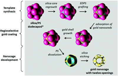
Fig. 1 schematically illustrates the multi-step process employed in the synthesis of the gold nanocages with twelve regularly-spaced and calibrated windows. We start from silica/PS dodecapods which may be described as icosahedral clusters of PS spheres attached to a central silica sphere of similar diameter. We then overgrow the core and functionalize the silica in the void space between the PS satellites via surface amination using N-[3-(trimethoxysilyl)-propyl]ethylenediamine (EDPS). The anchored amine moieties enable a regioselective coating by gold. The regioselective gold coating is obtained in two steps: the adsorption of tiny gold nanoparticles65 on the freshly aminated silica surface62 and their subsequent regrowth using a reducing agent (formaldehyde) and a gold plating solution (tetrachloroauric acid/potassium carbonate).63 Polyvinylpyrrolidone is added to the growth medium to prevent colloidal aggregation. Finally, by selective dissolution/etching of the silica/PS template, we release the nanocage. It presents the high symmetry of a hollow dodecahedron whose thirty edges are made of gold and slightly curved, and whose twelve faces are drilled with circular windows.We have previously reported the fabrication of the silica/PS dodecapod-like precursors at the gram scale by a seed-growth emulsion polymerization of styrene in the presence of 85 nm silica spheres.63 They are readily obtained with a morphological purity of ∼75%. The nature and proportion of the side-products, i.e. essentially clusters with a lower number of PS satellites or made of several silica cores, are described in Table S1 (ESI†).
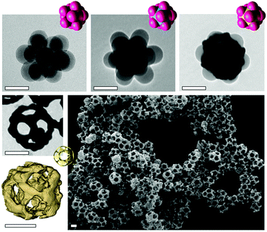
Due to its excellent spatial resolution, transmission electron microscopy (TEM) is well adapted for verifying the success of the different synthesis stages and analyzing the final morphology of the nanocages (Fig. 2). TEM images confirm the window morphology, their symmetrical arrangement and the hollow interior of the nanoparticles. The inner diameter, which corresponds to the value of the silica diameter after regrowth, is 125 nm. The windows are large and regularly distributed across the surface. Electron tomography reconstructs three-dimensional images of the nanoparticles, precisely measuring gold edges 20 nm in thickness and windows of 48 nm in diameter (Fig. 2 and Fig. S1, ESI†).
The gold shell is rather rough since the Au deposits consist of agglomerates of gold nanoparticles. The morphological yield of the nanocages is similar to that of the silica/PS dodecapod-like templates (∼75%), which shows that our synthesis pathway is very efficient at preserving the shape of the sacrificial template. The nanocages can have tunable dimensions, including the gold wall thickness and pore diameters. They can be adjusted by varying the total amount of gold or silica deposited during the multi-step process.
The simplicity and versatility of our approach was further evidenced by extending the strategy to the fabrication of nano-cages with 2, 3, 4 and 6 windows from bipod, tripod, tetrapod and hexapod silica/PS templates, respectively (Table S1 and Fig. S2–S5, ESI†). Gold maps obtained by scanning TEM coupled with energy-dispersive X-ray spectroscopy (STEM-EDX) of Fig. 3 show the morphologies of the as-obtained nanocages. They evidence that the high symmetry of the template is systematically transferred to the nanocages, especially the relative position of the windows, i.e. in line, triangular, tetrahedral and octahedral spatial windows. Similarly to the dodecapods, these nanocages can be produced on a large scale, as the templates are readily fabricated in gram quantities and with morphology purity from 66% to 91% (Table S1, ESI†).
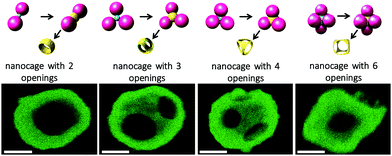 | ||
| Fig. 3 Top row: Schematic representation of silica/PS templates and intermediate morphologies, leading to the synthesis of nanocages with 2, 3, 4 and 6 windows. Bottom row: STEM-EDX gold maps of the corresponding nanocages (Au in green). Scale bars: 100 nm. TEM or SEM images of the different intermediates and resulting nanocages can be found in Fig. S2–S5 (ESI†), respectively, and the morphological features of the gold nanocages are compiled in Table S2 (ESI†). | ||
Detailed investigations of the optical responses of two types of synthesized nanocages, presenting four and twelve windows, performed in different environments (ensembles of nanoparticles in solution, or individual nanoparticles deposited on transparent and absorbing substrates) are presented in Fig. 4 and 5.
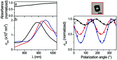
Average information on the optical properties of the produced gold nanocages can be obtained by measuring the absorbance of the synthesized solutions (proportional to the extinction of the nanocages according to Beer–Lambert law). The absorbance spectrum is obtained from nanocage dispersions having four windows, shown in Fig. 4a. It does not display any clear resonance in the 700–1050 nm wavelength range, and weakly increases with wavelength. However, this optical response does not necessarily reflect that of the individual nanocages present in the investigated solution, as absorbance measurements are affected by the nanoparticle polydispersity (which results in the broadening – or even complete obscuration – of optical resonances). These drawbacks can all be avoided by using spatial modulation spectroscopy (SMS), a single-particle technique based on the modulation of a nanoparticle position in a strongly focused laser beam which allows the quantitative determination of its extinction cross-section as a function of light wavelength and polarization.2,66,67
The extinction spectra measured for three individual gold nanocages with four windows deposited on a thin silica membrane are shown in Fig. 4b. These spectra differ considerably from the absorbance spectrum of the nanocage dispersion (Fig. 4a), highlighting that using a single-particle approach is indeed crucial for an accurate optical characterization of this sample (more generally, single particle approaches are especially useful in the case of colloidal solutions composed of nano-objects presenting a large dispersion in composition and morphology and/or when strong interactions between the nano-objects present in the solution modify their optical properties). Single-particle spectra are characterized by marked LSPRs centered at about 900 nm wavelength. The transmission electron microscopy images of the optically investigated nano-objects (one of them being shown in Fig. 4) confirm their four windows. The variation of the resonance position for the three investigated nanocages (from 890 to 950 nm) shows that the large width of the ensemble spectrum results at least partly from the morphological dispersion of the synthesized nano-objects. One could also a priori ascribe this LSPR variation to a different nanocage orientation on the underlying substrate, but the theoretical simulations presented below allow this hypothesis to be ruled out.
SMS also probes the effect of light polarization direction on nanoparticle optical extinction. Fig. 4c presents such measurements on the four nanocage windows. The extinction spectra show sinusoidal oscillations (with 180° period) with the polarization angle, as already observed in previous studies on elongated nano-objects such as nanorods.2,68 The amplitude of these polarization-induced variations is found here to be strongly particle-dependent (the minimal extinction cross-section representing 20, 50 and 80% of the maximal measurement for the three investigated nanoparticles), suggesting a morphological dispersion of the three synthesized nanocages.
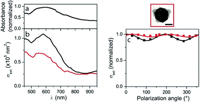
Strongly contrasting results were obtained for nanocages with twelve windows (Fig. 5). The absorbance of the correspond ding solution shows a single and broad resonance near 600 nm (Fig. 5a). The measured spectra for two individual nanocages (deposited on a thin carbon membrane) present different amplitudes, but their shapes remain similar to that of the solution absorbance spectrum (Fig. 5b), with also a resonance at 600 nm wavelength. Although, the ensemble and the single-particle spectra should be compared with care because the nanoparticle environment is not the same in the two cases (because of the necessity of depositing nanoparticles on a substrate for studying them individually), this indicates that the effect of morphological dispersion (and aggregation) are much weaker for this sample than for the four windows nanocages one. This is further confirmed by the measurement of a weak extinction polarization dependence (<10% variation) for both investigated twelve windows nanocages, which corresponds to the behavior theoretically expected for ideal nanocages (see below).
Optical experiments were complemented with numerical simulations of nanocage optical properties (Fig. 6). These simulations, based on finite-element modeling (FEM), were performed using the mean sizes deduced from a statistical analysis of the TEM images of the synthesized nanocages (Table S2, ESI†), assuming ideal nanocage morphology, and in particular perfectly smooth surfaces and regularly spaced windows. The synthesis intermediates (silica core and PS nodules) were respectively included and omitted when simulating nanocages with twelve and four windows, consistent with the TEM images of the nano-objects optically investigated (Fig. 4 and 5). The inhomogeneous environment of the particles in the SMS experiments resulting from their deposition on a substrate was also taken into account. Direct contact between the nanocages and the substrate was assumed, complementary simulations showing that the obtained results are weakly sensitive to the inclusion of a 1–2 nm separation between them (which could for instance result from an interfacial surfactant layer). Simulations were performed for multiple orientations of the nanocages, showing that this parameter has only a minor influence on their optical properties (Fig. 6).
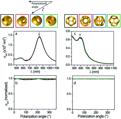 | ||
| Fig. 6 Simulated optical properties of nanocages with four (a and b) and twelve (c and d) windows: extinction spectra (a and c) and polarization-dependence (b and d) of extinction at resonance wavelengths (indicated by arrows in the respective panels (a and c)). Simulations were performed in the configuration of SMS experiments (nanocages deposited on a thin membrane), for different nanocage orientations generated by successive 30 degree rotations of the nanocage about an axis orthogonal to light propagation direction (the top views of the considered orientations are shown on top, each one being associated to a specific color). Simulations on nanocages with four windows were performed with 105 nm core diameter, 160 nm PS satellite diameter, 25 nm gold thickness and 40 nm thick silica substrate. Simulations on nanocages with twelve windows were performed with 125 nm core diameter, 85 nm PS satellite diameter, 20 nm gold thickness and 20 nm thick carbon substrate, including the silica core and PS nodules consistent with the TEM image shown in Fig. 5. An environmental refractive index of 1.1 and 1.3 was used for nanocages with twelve and four windows, respectively.68 | ||
Similarly to those measured via single-particle experiments, the extinction spectra computed for nanocages with four windows display a main, quasi-Lorentzian LSPR in the near-infrared domain. The characteristics of this resonance, extracted from a Lorentzian fit in the energy domain (850 nm central position, 280 meV spectral width and 7 × 10⁴ nm2 eV area) are close to those of the experimental spectra (890–950 nm central position, 210–250 meV and 6–7 × 10⁴ nm2 eV area). Such a good quantitative agreement, with only a slight blue-shift and broadening of the computed resonance as compared to experimental data, is remarkable considering the morphological complexity of the investigated nano-objects.
The extinction spectra computed for nanocages with twelve windows display a strongly asymmetric shape resulting from a partial spectral overlap of a main resonance centered at about 600 nm with an absorption background below 650 nm wavelength due to gold interband transitions. Computed spectra display marked similarities with experimental ones (Fig. 4), with also an extinction maximum near 600 nm. However, the general agreement is not as good as in the case of nanocages with four windows, in particular regarding extinction cross-section amplitudes in the infrared domain, which are larger in the measurements than in the simulations.
This may be the result of uncertainties in the determination of morphological parameters and/or deviation of the actual nanocage morphology from the ideal environment assumed in the modeling. The polarization dependence of nanocage resonance extinction cross-sections was also investigated (Fig. 6b and d) by reproducing the calculations shown in panels a and c for different directions of the polarization of the linearly polarized incident plane wave (wavelength being fixed to its resonance value). These computations yield sinusoidal variations of extinction with polarization angle, similar to the experimental case. Nanocage orientation is predicted to have an impact on the amplitude (and phase) of the polarization dependence. However, the computed polarization-induced extinction variations are of less than 5% in all considered cases. This numerical result is consistent with the small polarization dependence observed for nanocages with twelve windows. It also implies that the large polarization dependence measured for the extinction of some nanocages with four windows stems from effects not included in the FEM simulations. It probably originates from imperfections in the window morphology and spacing in the actual nano-objects (while such effects may also occur for nanocages with twelve windows, individual windows imperfections are more likely to average out due to the much higher number of windows).
The synthetic approach presented in this paper can be extended to create hollow nanostructures with a more complex architecture, such as rattle-like nanostructures, consisting of a gold cage containing a guest nano-object. Hajfathalian et al. recently reported the confinement of a Wulff-shaped core within a metallic nanocage of different shape and nature,69 but their synthetic approach requires a solid substrate onto which the Wulff-shaped core is first fabricated by thermal dewetting of a thin film, which represents a severe limitation regarding the quantity of nanostructures that can be produced. In our case, all the stages of the synthetic route occur in solution allowing upscaling. We demonstrated that our strategy does actually entrap nano-objects within the gold nanocage by replacing the silica seeds used for the fabrication of the silica/PS multipods by core@shell nanoparticles made of magnetite (γ-Fe3O4) cores surrounded by a thin silica shell.70 Because their size distribution was larger than that of the conventional silica seeds, the as-obtained maghemite/silica/PS multipod nanoparticles are indeed a more complex mixture of bipods to dodecapods (Table S1, ESI†). Thus in this single experiment, we show that the maghemite/silica core can generate all desired nanocages morphologies. Since the magnetite core can dissolve in hydrofluoric acid, we stopped the fabrication process after the dissolution of the PS nodules. Fig. 7 shows Fe, Si and Au element mapping obtained by STEM-EDX of nanocages with 2, 3, 4, 6 and 12 windows. This approach offers a unique capability to create new hollow nanostructures formed by different components (metal, semiconductor, dielectric), and to combine and modify their individual properties via their interaction (for instance through the strongly enhanced electromagnetic field inside the core of the cage due to plasmonic effect). It opens new ways towards the design of hollow nano-objects.
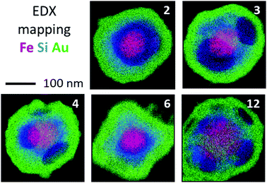 | ||
| Fig. 7 STEM-EDX superimposed elemental maps of the Au hollow structures with respectively 2, 3, 4, 6 and 12 windows filled with a spherical Fe3O4 nanoparticle (Fe in red, Si in blue and Au in green). Original STEM images and individual element maps can be seen in Fig. S6–S9 (ESI†), respectively. | ||
Conclusions
We demonstrated a new strategy to fabricate gold nanocages, with a control over the number (from 2 to 12) and the relative positioning of the windows, through a multi-step colloidal approach. The frame of the nanocages does exhibit a roughness of a few nanometers that could be smoothed via post-treatment, for example by oxidation etching. The extinction spectra of some of these structures were measured using single-particle spectroscopy. The specific features of the plasmonic hollow nanostructures are well correlated with those computed numerically, assuming perfectly symmetrical nanocage geometries. We demonstrated that our synthesis approach allows a guest spherical particle of iron oxide to be included within the nanocages. More broadly, this route offers a promising strategy to design and construct multifunctional architectures based on porous hollow nanostructures. As it can be adapted to numerous systems (noble and non noble metals, metal oxide or chalcogenide), it may enable a variety of fundamental studies and technological important applications in various fields including biological medicine, sensing and detection, energy conversion and catalysis.71–73Experimental
Synthetic procedures of Au nanocages
Silica/polystyrene multipods-like particles. Multipods made of a central silica core and a predetermined number of PS satellite nodules were obtained after a procedure previously published in detail.63,64 It consists in a seeded-growth emulsion polymerization of styrene using highly monodisperse silica nanoparticles surface-modified with methacryloxyalkyl groups as seeds. We used different batches of multipods dispersed in water (Table S1, ESI†), whose number of PS nodules was controlled by playing with the seed concentration and/or the satellite-to-seed size ratio. Their concentration was determined by the dried extracts method. More details are shown in ESI.†
Regrowth and amination of the silica core. We mixed 1 mL aqueous dispersion of multipods, 45.5 mL absolute ethanol of TEOS (tetraethoxysilane) depending on the expected regrowth extent. We added this solution at the rate of 0.5 mL h−1 and the mixture was stirred at room temperature for 12 h. Then a calculated volume of EDPS, corresponding to 20 functions per nm2 of free silica surface area, was added to the particle dispersion, which was let to age at 40 °C for 2 h. The as-prepared templates were purified by 3 cycles of centrifugation/redispersion in absolute ethanol. The final concentration of the templates was accurately determined by the dried extracts method and adjusted to 7.3 1015 particles L−1. For each batch of silica/PS multipods, the final diameter of the silica core was determined from transmission electron microscopy images (Table S1, ESI†).
More details of experimental section, e.g. Chemicals, Characterization and simulations, can be found in ESI.†
Author contributions
Conceptualization, E. D., S. R. and M. T.-D.; Investigation, A. C., A. D., A. M., C. C., C. H., I. F. and D. I.; Optical experiments A. L., E. P., P. M. and F. Vi.; Formal Analysis, A. P., E. D., O. E., A. C., N. D.-F., S. R. and M. T.-D.; Writing draft, A. C., A. P., E. D., S. R. and M. T.-D.; Review & Editing, N. D.-F., O. E. and F. Va.; Funding Acquisition, E. D., S. R. and M. T.-D.Conflicts of interest
There are no conflicts to declare.Acknowledgements
STEM-EDX analyses were performed at the Plateforme Aquitaine de Caractérisation des Matériaux and Bordeaux Imaging Center of the University of Bordeaux. This work was supported by the Conseil Régional d’Aquitaine, the Agence Nationale de la Recherche (grant ANR-07-BLAN-0271 and ANR-BLAN-SIMI10-LS-100617-15-01), and the LabEx AMADEus (ANR-10-LABX-42) in the framework of IdEx Bordeaux (ANR-10-IDEX-03-02), i.e. the Investissements d’Avenir programme of the French government. The authors acknowledge Dr Véronique Many for some parallel experiments, Dr Laurent Adumeau and Dr Stéphane Mornet for helpful discussion, and Dr Yohan Grand for SEM experiments performed at ITODYS laboratory (UMR 7086, Univ. Paris Diderot).References
- M. Ha, J. Kim, M. You, Q. Li, C. Fan and J. Nam, Chem. Rev., 2019, 119, 12208 CrossRef CAS.
- A. Crut, P. Maioli, N. D. Fatti and F. Vallée, Chem. Soc. Rev., 2014, 43, 3921 RSC.
- M. Grzlczak, L. Liz-Marzan and R. Klajn, Chem. Soc. Rev., 2019, 48, 1342 RSC.
- H. A. Atwater and A. Polman, Nat. Mater., 2010, 9, 205 CrossRef CAS.
- M. E. Stewart, C. R. Anderton, L. B. Thompson, J. Maria, S. K. Gray, J. A. V. Rogers and R. G. Nuzzo, Chem. Rev., 2008, 108, 494 CrossRef CAS.
- B. Luk’yanchuk, N. I. Zheludev, S. A. Maier, N. J. Halas, P. Nordlander, H. Giessen and C. T. Chong, Nat. Mater., 2010, 9, 707 CrossRef.
- Y. Xia, Y. Xiong, B. Lim and S. E. Skrabalak, Angew. Chem., Int. Ed., 2009, 48, 60 CrossRef CAS.
- Y. Xia, J. A. Rogers, K. E. Paul and G. M. Whitesides, Chem. Rev., 1999, 99, 1823 CrossRef CAS.
- B. D. Gates, Q. Xu, M. Stewart, D. Ryan, C. G. Willson and G. M. Whitesides, Chem. Rev., 2005, 105, 1171 CrossRef CAS.
- M. R. Jones, K. D. Osberg, R. J. Macfarlane, M. R. Langille and C. A. Mirkin, Chem. Rev., 2011, 111, 3736 CrossRef CAS.
- H. W. Deckman and J. H. Dunsmuir, Appl. Phys. Lett., 1982, 41, 377 CrossRef CAS.
- J. C. Hulteen and R. P. Van Duyne, J. Vac. Sci. Technol., A, 1995, 13, 1553 CrossRef.
- H. Zheng, R. Vallée, I. Ly, R. M. Almeida, T. Rivera and S. Ravaine, J. Phys. Chem. C, 2016, 120, 1178 CrossRef CAS.
- S. J. Hurst, E. K. Payne, L. Qin and C. A. Mirkin, Angew. Chem., Int. Ed., 2006, 45, 2672 CrossRef CAS.
- C. J. Brumlik, V. P. Menon and C. R. Martin, J. Mater. Res., 1994, 9, 1174 CrossRef CAS.
- L. M. Liz-Marzan, M. Giersig and P. Mulvaney, Langmuir, 1996, 12, 4329 CrossRef CAS.
- M. J. Mulvihill, X. Y. Ling, J. Henzie and P. Yang, J. Am. Chem. Soc., 2010, 132, 268 CrossRef CAS.
- C. Xue, J. E. Millstone, S. Li and C. A. Mirkin, Angew. Chem., Int. Ed., 2007, 46, 8436 CrossRef CAS.
- C. W. Yen, M. A. Mahmoud and M. A. El-Sayed, J. Phys. Chem. A, 2009, 113, 4340 CrossRef CAS.
- M. A. Mahmoud, D. O’Neil and M. A. El-Sayed, Chem. Mater., 2014, 26, 44 CrossRef CAS.
- M. Nazemi, S. R. Panikkanvalappil and M. A. El-Sayed, Nano Energy, 2018, 49, 316 CrossRef CAS.
- B. Pang, X. Yang and Y. Xia, Nanomedicine, 2016, 11, 1715 CrossRef CAS.
- S. Lepinay, A. Staff, A. Ianoul and J. Albert, Biosens. Bioelectron., 2014, 52, 337 CrossRef CAS.
- L. Tian, K. K. Liu, J. J. Morrissey, N. Gandra, E. D. Kharasch and S. Singamaneni, J. Mater. Chem. B, 2014, 2, 167 RSC.
- M. Hu, J. Chen, Z. Y. Li, L. Au, G. V. Hartland, X. Li, M. Marquez and Y. Xia, Chem. Soc. Rev., 2006, 35, 1084 RSC.
- M. A. Mahmoud and M. A. El-Sayed, J. Am. Chem. Soc., 2010, 132, 12704 CrossRef CAS.
- M. A. Mahmoud, B. Snyder and M. A. El-Sayed, J. Phys. Chem. C, 2010, 114, 7436 CrossRef CAS.
- G. Ferraro, D. M. Monti, A. Amoresano, N. Pontillo, G. Petruck, F. Pane, M. A. Cinellu and A. Merlino, Chem. Commun., 2016, 52, 9518 RSC.
- G. Wang, W. Gao, X. Zhang and X. Mei, Sci. Rep., 2016, 6, 28258 CrossRef CAS.
- X. Yang, K. D. Gilroy, M. Vara, M. Zhao, Z. Ming, S. Zhou and Y. Xia, Chem. Phys. Lett., 2017, 683, 613 CrossRef CAS.
- J. Chen, F. Saeki, B. J. Wiley, H. Cang, M. J. Cobb, Z. Y. Li, L. Au, H. Zhang, M. B. Kimmey, Y. Li and Y. Xia, Nano Lett., 2005, 5, 473 CrossRef CAS.
- K. H. Song, C. Kim, C. M. Cobley, Y. Xia and L. V. Wang, Nano Lett., 2009, 9, 183 CrossRef CAS.
- Y. Wang, Y. Liu, H. Luehmann, X. Xia, D. Wan, C. Cutler and Y. Xia, Nano Lett., 2013, 13, 581 CrossRef CAS.
- S. Cheemalapati, M. Ladanov, B. Pang, Y. Yuan, P. Koria, Y. Xia and A. Pyayt, Nanoscale, 2016, 8, 18912 RSC.
- S. Bao, S. Huang, Y. Liu, Y. Hu, W. Wang, M. Ji, H. Li, N. X. Zhang, C. Song and S. Duan, Nanoscale, 2017, 9, 7284 RSC.
- Y. Sun, B. T. Mayers and Y. Xia, Nano Lett., 2002, 2, 481 CrossRef CAS.
- K. An and T. Hyeon, Nano Today, 2009, 4, 359 CrossRef CAS.
- S. E. Skrabalak, J. Chen, Y. Sun, X. Lu, L. Au, C. M. Cobley and Y. Xia, Acc. Chem. Res., 2008, 41, 1587 CrossRef CAS.
- J. Zeng, Y. Ma, U. Jeong and Y. Xia, J. Mater. Chem., 2010, 20, 2290 RSC.
- Y. Sun and Y. Xia, Science, 2002, 298, 2176 CrossRef CAS.
- L. M. Moreau, C. A. Schurman, S. Kewalramani, M. M. Shahjamali, C. A. Mirkin and M. J. Bedzyk, J. Am. Chem. Soc., 2017, 139, 12291 CrossRef CAS.
- K. D. Gilroy, A. Sundar, P. Farzinpour, R. A. Hughes and S. Neretina, Nano Res., 2014, 7, 365 CrossRef CAS.
- J. Ahn, D. Wang, Y. Ding, J. Zhang and D. Qin, ACS Nano, 2018, 12, 298 CrossRef CAS.
- Y. Sun and Y. Xia, J. Am. Chem. Soc., 2004, 126, 3892 CrossRef CAS.
- J. Chen, J. M. McLellan, A. Siekkinen, Y. Xiong, Z. Y. Li and Y. Xia, J. Am. Chem. Soc., 2006, 128, 14776 CrossRef CAS.
- C. M. Cobley and Y. Xia, Mater. Sci. Eng., R, 2010, 70, 44 CrossRef.
- Z. Fang, Y. Wang, C. Liu, S. Chen, W. Sang, C. Wang and J. Zeng, Small, 2015, 11, 2593 CrossRef CAS.
- X. Lu, L. Au, J. McLellan, Z. Y. Li, M. Marquez and Y. Xia, Nano Lett., 2007, 7, 1764 CrossRef CAS.
- F. Lu, H. Xin, W. Xia, M. Liu, Y. Zhang, W. Cai and O. Gang, ACS Cent. Sci., 2018, 4, 1742 CrossRef CAS.
- H. M. Chen, R. S. Liu, K. Asakura, J. F. Lee, L. Y. Jang and S. F. Hu, J. Phys. Chem. B, 2006, 110, 19162 CrossRef CAS.
- J. Yang, L. Lu, H. Wang and H. Zhang, Scr. Mater., 2006, 54, 159 CrossRef CAS.
- E. González, J. Arbiol and V. F. Puntes, Science, 2011, 334, 1377 CrossRef.
- W. Zhang, M. Rahmani, W. Niu, S. Ravaine, M. Hong and X. Lu, Sci. Rep., 2015, 5, 8382 CrossRef CAS.
- Y. Sun and Y. Xia, Adv. Mater., 2004, 16, 264 CrossRef CAS.
- J. Cheng, N. Mallet, W. Baaziz, O. Ersen, E. Gombart, V. Alard, J. Majimel, M. H. Delville, M. Tréguer-Delapierre and E. Duguet, Chem. – Eur. J., 2018, 24, 6917 CrossRef CAS.
- F. Li, C. Yoo, M. Beernink and A. Stein, J. Am. Chem. Soc., 2009, 131, 18548 CrossRef CAS.
- S. J. Oldenburg, G. D. Hale, J. B. Jackson and N. J. Halas, Appl. Phys. Lett., 1999, 75, 1063 CrossRef CAS.
- S. J. Oldenburg, J. B. Jackson, S. L. Westcott and N. J. Halas, Appl. Phys. Lett., 1999, 75, 2897 CrossRef CAS.
- S. J. Oldenburg, R. D. Averitt, S. L. Westcott and N. J. Halas, Chem. Phys. Lett., 1998, 288, 243 CrossRef CAS.
- S. J. Oldenburg, S. Westcott, R. D. Averitt and N. J. Halas, J. Chem. Phys., 1999, 111, 4729 CrossRef CAS.
- Z. Cai, E. S. P. Leong, Z. Wang, W. Niu, W. Zhang, S. Ravaine, N. L. Yakovlev, Y. J. Liu, J. Teng and X. Lu, J. Mater. Chem. C, 2015, 3, 11645 RSC.
- C. Hubert, C. Chomette, A. Désert, M. Sun, M. Treguer-Delapierre, S. Mornet, A. Perro, E. Duguet and S. Ravaine, Faraday Discuss., 2015, 181, 139 RSC.
- V. Many, R. Dézert, E. Duguet, A. Baron, V. Jangid, V. Ponsinet, S. Ravaine, P. Richetti, P. Barois and M. Tréguer-Delapierre, Nanophotonics, 2019, 8, 549 CAS.
- A. Désert, J. Morele, J. C. Taveau, O. Lambert, M. Lansalot, E. Bourgeat-Lami, A. Thill, O. Spalla, L. Belloni, S. Ravaine and E. Duguet, Nanoscale, 2016, 8, 5454 RSC.
- D. G. Duff, A. Baiker and P. P. Edwards, Langmuir, 1993, 9, 2301A CrossRef.
- A. Arbouet, D. Christofilos, N. Del Fatti, F. Vallée, J. R. Huntzinger, L. Arnaud, P. Billaud and M. Broyer, Phys. Rev. Lett., 2004, 93, 127401 CrossRef CAS.
- A. Crut, P. Maioli, F. Vallée and N. Del Fatti, J. Phys.: Condens. Matter, 2017, 29, 123002 CrossRef.
- A. Lombardi, M. Loumaigne, A. Crut, P. Maioli, N. D. Fatti, F. Vallée, M. Spuch-Calvar, J. Burgin, J. Majimel and M. Tréguer-Delapierre, Langmuir, 2012, 28, 9027 CrossRef CAS.
- M. Hajfathalian, K. D. Gilroy and S. D. Golze, ACS Nano, 2016, 10, 6354 CrossRef CAS.
- E. Yammine, L. Adumeau, M. Abboud, S. Mornet, M. Nakhl and E. Duguet, Nanomaterials, 2021, 11, 147 CrossRef.
- Z. Weng, J. Xie, C. Bi, H. Xin, Y. Wang and X. Cao, Analyst, 2019, 144, 7250 RSC.
- M. Ottonelli, Z. Zappia, A. Demartini and M. Alloisio, Nanomaterials, 2020, 10, 224 CrossRef CAS.
- T. Aubert, K. Ma, K. Tan and U. Wiesner, Adv. Mater., 2020, 32, 1908362 CrossRef CAS.
Footnote |
| † Electronic supplementary information (ESI) available. See DOI: 10.1039/d0nh00620c |
| This journal is © The Royal Society of Chemistry 2021 |

