
 Open Access Article
 This Open Access Article is licensed under a Creative Commons Attribution-Non Commercial 3.0 Unported Licence
Heterojunction-based photocatalytic nitrogen fixation: principles and current progress
Hassan
Ali
 ,
Milan
Masar
,
Ali Can
Guler
,
Michal
Urbanek
,
Michal
Machovsky
* and
Ivo
Kuritka
,
Milan
Masar
,
Ali Can
Guler
,
Michal
Urbanek
,
Michal
Machovsky
* and
Ivo
Kuritka
Centre of Polymer Systems, Tomas Bata University in Zlin, Tr. T. Bati 5678, 76001 Zlin, Czech Republic. E-mail: machovsky@utb.cz
First published on 16th September 2021
Abstract
Nitrogen fixation is considered one of the grand challenges of the 21st century for achieving the ultimate vision of a green and sustainable future. It is crucial to develop and design sustainable nitrogen fixation techniques with minimal environmental impact as an alternative to the energy–cost intensive Haber–Bosch process. Heterojunction-based photocatalysis has recently emerged as a viable solution for the various environmental and energy issues, including nitrogen fixation. The primary advantages of heterojunction photocatalysts are spatially separated photogenerated charge carriers while retaining high oxidation and reduction potentials of the individual components, enabling visible light-harvesting. This review summarises the fundamental principles of photocatalytic heterostructures, the reaction mechanism of the nitrogen reduction reaction, ammonia detection methods, and the current progress of heterostructured photocatalysts for nitrogen fixation. Finally, future challenges and prospects are briefly discussed for the emerging field of heterostructured photocatalytic nitrogen fixation.
 Hassan Ali | Hassan Ali received his Masters degree in Chemical Technology from AGH University of Science and Technology, Krakow, Poland in 2017. Then, he joined the Centre of Polymer Systems at Tomas Bata University in Zlin, Czechia, in 2019. His research interest primarily focuses on the development of improved photocatalytic and photoelectrochemical materials for environmental sustainability, such as pollutant degradation, water splitting, N2 fixation, and CO2 reduction. |
 Michal Machovsky | Michal Machovsky received his PhD degree in Technology of Macromolecular Compounds from Tomas Bata University in Zlin (TBU) in 2013 and currently holds the position of senior researcher in the research group of Nanomaterials and Advanced Technologies at the Centre of Polymer Systems at TBU. His research interests cover broad aspects of nanomaterial synthesis and characterization with focus on development of heterostructured photocatalysts, antimicrobials, and polymer nanocomposites. He published more than 50 papers indexed in WoS, h-index-16. |
 Ivo Kuritka | Ivo Kuritka received his PhD degree in Technology of Macromolecular Compounds from Tomas Bata University in Zlin (TBU) in 2005 and habilitation in the same field in 2009. Currently, he is a head of the research group of Nanomaterials and Advanced Technologies at the Centre of Polymer Systems at TBU. His research interests include nanomaterial synthesis and characterization, photocatalysis and energy conversion, sensors and other electronic devices, and spectroscopy. He is a member of the Ammonia Energy Association and the Czech Chemical Society. He contributed more than 130 papers in WoS, h-index 22. He supervised 15 successfully defended dissertations. |
1. Introduction
The nitrogen fixation process is an important chemical process in which inert nitrogen gas molecules are converted into ammonia (NH3) and other nitrogenous compounds such as nitrates. Nitrogen is essential for all living organisms on the planet, as it is utilised in the formation of various building blocks of organisms, such as proteins, amino acids, and nucleotides for DNA and RNA.1 Despite being the most abundant and ubiquitous gas in the atmosphere (∼78%),2 nitrogen cannot be directly utilised before it is “fixed” or converted to other innocuous nitrogen derivates. However, nitrogen fixation to NH3 or nitrates is an energy-intensive process due to the triple bond cleavage of the dinitrogen molecule.3 Broadly, nitrogen fixation is accomplished via three main routes, i.e., (i) biological nitrogen fixation, (ii) geochemical nitrogen fixation, and (iii) artificial nitrogen fixation.4–6 In nature, biological nitrogen fixation (BNF) is accomplished by a special enzyme called nitrogenase consisting of iron, a sulphur-based cofactor, and a heterometal complex, usually molybdenum.1 Moreover, some geochemical processes, such as lightning and volcanic activity, also account for a minor portion of the fixed nitrogen supply.7 During the early 20th century, the demand for fixed nitrogen supply obtained solely via natural processes could not be met due to the ever-growing human population. Therefore, in 1903 Birkland and Eyde developed a process to generate nitric acid (HNO3) from atmospheric nitrogen using energy-intensive plasma generated via electric current. However, the process was not well suited for large-scale HNO3 synthesis due to the energy-intensive production of HNO3 (2.4 MJ mol−1).8 In 1908, Fritz Haber and Carl Bosch developed a relatively low energy-consuming process to convert nitrogen gas to NH3 at the temperature and pressure range of 400–500 °C and 150–200 atm, respectively.9 The Haber–Bosch (HB) process is considered one of the most important chemical reactions of the 20th century, which led to rapid industrialisation and human population growth over the last century. However, the considerable energy consumption required for the HB process, which is supplied in the form of H2 gas, mainly obtained via steam reforming, leads to the emission of large amounts of greenhouse gases. Statistically, the HB process consumes 1–2% of the global energy supply and generates about 3% of the total global CO2 emissions.10,11 Moreover, due to the ever-growing human population, the demand for fixed nitrogen is gradually rising while excess nitrogen is slowly discharged into rivers.12As a consequence of these anthropogenic activities, the natural nitrogen cycle is disturbed, resulting in severe environmental concerns, such as the greenhouse effect, ozone layer depletion, acid rain, and contamination of freshwater sources.13,14 In a broader scenario, photocatalytic nitrogen fixation is one of the several emerging power-to-X (P2X) technologies in which abundant renewable energy resources are utilised to generate high energy density chemicals, such as H2, methane, and NH3. These hydrogen-rich chemicals generate relatively high heat per unit mass, enabling greater flexibility in energy storage, transport, and decarbonisation of the conventional fossil fuel-based energy infrastructure.15 Therefore, it is critical to develop and design new strategies that are environmentally sustainable for nitrogen fixation, keeping in view the stringent environmental regulations. Currently, the US Academy of Engineering has listed sustainable management of nitrogen fixation and its cycle as one of the fourteen grand challenges for engineering in the 21st century.16 Therefore, several concerted efforts have been devoted to the development of an environmentally friendly process for atmospheric nitrogen fixation under mild conditions with minimal energy and cost.17 These include, albeit still in early stages, bio-assisted catalysis, thermally assisted catalysis, and photocatalysis.17–19 Among these approaches, photocatalysis has already been employed in several applications for years with commendable success, such as water treatment, pollutant degradation, bio-organic waste treatment, and bactericidal drugs.20–22 This diverse range of applications has stimulated great research interest, and as a result, photocatalysis has recently emerged as a promising solution for sustainable environmental nitrogen fixation. In 1977, Guth et al. reported on the nitrogen reduction reaction over a TiO2 photocatalyst and Fe2O3 as a cocatalyst.23 Subsequently, Schrauzer et al., in 1983, demonstrated the capability of natural physicochemical nitrogen photofixation of iron titanate in desert sands formed by weathering of ilmenite-rich rocks. It was estimated that the global abiological N2 fixation via titania-rich desert sand contributed significantly, corresponding to about ten per cent of biologically reduced N2.24 Since then, a wide variety of photocatalytic semiconducting materials have been explored, such as metal oxides, metal sulphides, layered double hydroxides, and carbonaceous materials.25–29
Despite the substantial progress that has been made in photocatalytic nitrogen fixation, several issues must be addressed before any practical significance can be achieved. Firstly, the nitrogen reduction reaction (NRR) and hydrogen evolution reaction (HER) possess similar reduction potentials, and thus the selectivity for the NRR is reduced in favour of the HER in aqueous electrolytes.30,31 Secondly, the lack of suitable adsorption and activation sites for stable N![[triple bond, length as m-dash]](https://www.rsc.org/images/entities/char_e002.gif) N molecules onto the surface of photocatalysts results in sluggish kinetics of the NRR.32 Furthermore, the high recombination rate of charge carriers and poor visible light-harvesting result in low overall photocatalytic nitrogen fixation.33 In general, several modification strategies for enhancing the photoactivity of photocatalysts have been developed, as single-component photocatalysts usually suffer from poor efficiencies. These strategies include loading of cocatalysts, introduction of defects, and formation of heterojunctions.34 Heterojunction-based photocatalysts currently have the highest potential to achieve enhanced photocatalytic activity owing to the charge transfer mechanism and the separation of photogenerated charge carriers, which is a critical issue in single-component photocatalysts.35
N molecules onto the surface of photocatalysts results in sluggish kinetics of the NRR.32 Furthermore, the high recombination rate of charge carriers and poor visible light-harvesting result in low overall photocatalytic nitrogen fixation.33 In general, several modification strategies for enhancing the photoactivity of photocatalysts have been developed, as single-component photocatalysts usually suffer from poor efficiencies. These strategies include loading of cocatalysts, introduction of defects, and formation of heterojunctions.34 Heterojunction-based photocatalysts currently have the highest potential to achieve enhanced photocatalytic activity owing to the charge transfer mechanism and the separation of photogenerated charge carriers, which is a critical issue in single-component photocatalysts.35
To the best of our knowledge, there is no compilation of the latest reported studies dedicated solely to the type-II and Z-scheme-based photocatalysts towards the application of nitrogen fixation. In this review, we summarise the recent progress in heterojunction-based photocatalytic nitrogen fixation. A brief introduction to the fundamentals of heterojunction-based photocatalysis, the mechanism of BNF, ammonia detection methods, and the current progress in photocatalytic nitrogen fixation is reviewed. Finally, this review concludes with the prospects of achieving nitrogen fixation via photocatalysis.
2. Reaction mechanism of nitrogen fixation
2.1 Biological nitrogen fixation
In nature, biological nitrogen fixation (BNF) is primarily carried out by microbes known as azotobacter via a special enzyme called nitrogenase under room temperature and atmospheric pressure. The most common nitrogenase is a two-component system comprising (i) a FeMo protein which acts as a binding and reduction site for N2 molecules and (ii) an iron-containing protein responsible for providing reducing electrons.1 The reaction is initiated by the transfer of electrons from a pair of adenosine triphosphate (ATP) molecules to the Fe–S cluster located inside the Fe protein and subsequently to the FeMo cofactor (FeMoco), the active binding and reduction site for nitrogen atoms1,36 (see Fig. 1). Kinetic measurements have shown that nitrogen fixation via the nitrogenase enzyme is not a typical reduction of N2 by six electrons and protons but proceeds by the following equation.| N2 + 8e− + 16ATP + 16H2O + 8H+ → 2NH3 + H2 + 16ADP + 16Pi, ΔG0 = −641 kJ mol−1 (ref. 37) |
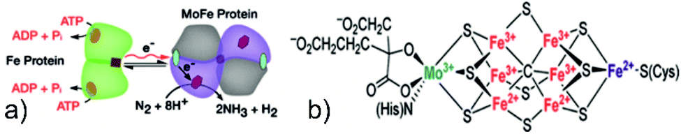 | ||
| Fig. 1 (a) Reaction pathway of the nitrogenase enzyme. Reproduced with permission from ref. 36. Copyright 2016, AAAS. (b) Structure of FeMoco, the active site for the NRR. Reproduced with permission from ref. 132. Copyright 2016, American Chemical Society. | ||
This balanced equation shows the involvement of ATP hydrolysis and the formation of one mole of H2 per mole of N2 reduced. Nitrogenase cofactor (FeMoco) is one of the most complex metal clusters in nature; thus, its precise reaction mechanism and binding action are still a subject of vivid scientific discussion.38 It is pertinent here to compare the energetics of ammonia synthesis accomplished by the HB process and BNF. Considering the mild operational conditions of BNF, it may seem that BNF provides a more energetically feasible pathway as compared to the HB process; however, stoichiometric calculation results in an overpotential of 117 kcal mol−1, in comparison to a chemical overpotential of 14 kcal mol−1, associated with the HB process, indicating a relatively more energy-efficient process.39 Nevertheless, there is a need for an eco-friendly ammonia synthesis process due to the excessive amount of H2 consumed in the HB process, mainly obtained via fossil fuels. In this regard, researchers have tried to mimic the catalytic activity of nitrogenase for NH3 synthesis by designing several biomimetic photocatalysts containing Fe, Mo, and V elements, such as Mo–PCN,40 MoO2/BiOCl,41 Bi3FeMo2O12,42 Mo0.1Ni0.1Cd0.8S,43 and FeMoS–FeS–SnS.44 The nitrogen fixation rate for these nitrogenase-inspired biomimetic photocatalysts has shown promising results but is still far lower than what is desired for practical feasibility. In summary, to achieve a viable artificial nitrogen reduction, a clear understanding of the nitrogenase reaction mechanism, optimised crystal morphology, and structure of the photocatalysts shall be highly useful.
2.2 Electrocatalytic reaction mechanism of nitrogen fixation
The electrocatalytic reduction of nitrogen is of particular interest for the ammonia production industry owing to its relatively mild operating conditions with high efficiency in comparison to the HB process. A typical electrocatalytic N2 reduction system consists of a three-electrode setup that utilises an aqueous electrolyte with oxygen and hydrogen evolution reactions at the anode and cathode, respectively. The only required inputs are water (as proton and electron source), air, electrocatalyst, and electricity (conceivably obtained from renewable energy sources). The overall balanced equations for the reactions occurring at the anode and cathode in the case of proton-conducting electrolytes are expressed below:45,46Anode (acidic conditions):
| 3H2O → 3/2O2 + 6H+ + 6e− | (1) |
Anode (basic conditions):
| 6OH− → 3H2O + 3/2O2 + 6e− | (2) |
Cathode (acidic conditions):
| N2 + 6H+ + 6e− → 2NH3 | (3) |
Cathode (acidic conditions):
| N2 + 6H2O + 6e− → 2NH3 + 6OH− | (4) |
Overall reaction:
| N2 + 3H2O → 3/2O2 + 2NH3 | (5) |
The current industrial ammonia synthesis by the HB process requires an energy input of 3.5 × 10⁴ to 5.0 × 10⁴ J gNH3−1. Alternative ammonia strategies can only be considered viable for practical significance if their energy requirements are considerably below those of the HB process. In this context, an electrochemical system capable of achieving faradaic efficiency of 50% would consume an overall energy of 1.9 × 10⁵ J gNH3−1 for the N2 reduction. Similarly, a 10% solar to chemical (SSC) efficiency would result in an energy consumption of ≈2.1 × 10⁵ J gNH3−1.47 However, both the faradaic efficiency and SSC values for ammonia synthesis remain unsatisfactory to date. Therefore, the research is mainly focused on increasing the faradaic efficiency by minimising the electrolytic resistance, increasing the conductivity, minimising thickness, suppression of the HER, and low operational temperature for solid-state ionic conductors. Preferably, all electrocatalysts should possess stronger synergistic interaction with N2 molecules than their intermediates. Nørskov and his co-workers carried out theoretical calculations which revealed that apart from selectivity, poor electrochemical NH3 synthesis is limited by the difference in the binding energies of two key adsorbates, *N2H and *NH2, in accordance with the other relevant studies.48,49 Their study concluded that for designing optimised electrocatalysts, two key points should be considered, i.e., selective stabilisation of *N2H and destabilisation of *NH2 or *NH intermediates. To date, various materials and systems have been explored for the electrocatalytic synthesis of NH3, employing a variety of catalysts and electrolytes.50 Herein, a hybrid plasma and electrocatalytic based system, recently demonstrated as a proof of concept by Amal and her co-workers, is worth mentioning.51 The system was intentionally designed to generate nitrogen oxides (3.8 kW h mol−1) from N2 due to their high reactivity compared to the highly stable N2via a non-thermal plasma. The generated NOx intermediates were subsequently converted to NH3 at a rate of 23.2 mg h−1, showing the potential for scalable green NH3 production.51 However, in contrast to electrocatalytic N2 reduction, photocatalytic N2 reduction offers a fundamentally sustainable approach due to the low cost and energy. The input electrical energy is substituted by solar energy, and the frequent replacement of electrodes is avoided in photocatalytic N2 fixation.
2.3 Photocatalytic reaction mechanism of nitrogen fixation
The photocatalytic nitrogen fixation reaction mechanism is similar to the other photocatalytic processes, such as water splitting, CO2 reduction, and pollutant degradation, i.e., production of highly active radicals and disassociation of water molecules. A photocatalytic reaction involves three primary steps: (i) the creation of electron–hole pairs after the absorption of incident solar energy photons greater than the bandgap of the semiconductor, (ii) the migration of charge carriers to the surface without futile recombination, and (iii) spatially separated electrons and holes participating in the reduction and oxidation reactions, respectively.52 A schematic illustration of a typical photocatalytic process over a single-component photocatalyst is given in Fig. 2.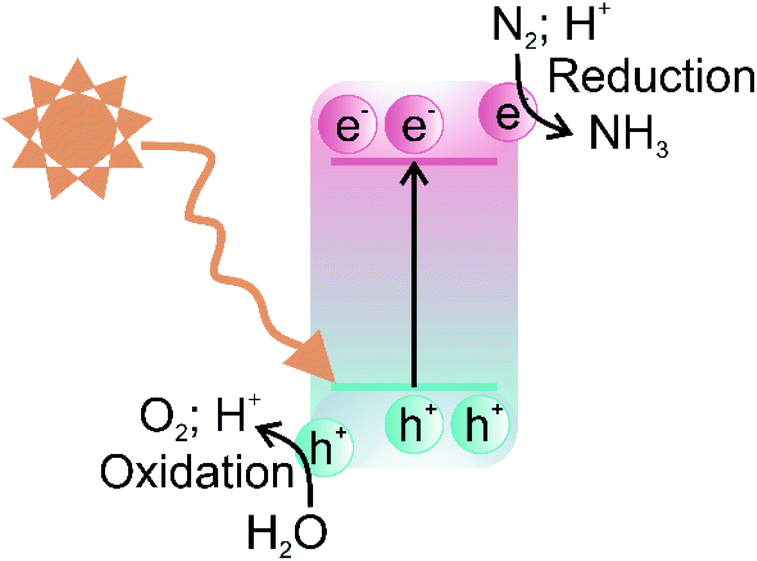 | ||
| Fig. 2 Schematic illustration of the photocatalytic process of a single-component photocatalyst. | ||
The efficiency of a photocatalyst relies on a suitable balance between its thermodynamics and the kinetics of the reaction processes. Since nitrogen fixation primarily occurs via the reduction pathway, the photoexcited electrons are responsible for reducing N2 molecules to NH3, although the oxidation pathway can generate nitric acid (NO3−) via photoexcited holes.53 Therefore, the selection of photocatalysts for nitrogen fixation is reliant on materials exhibiting high redox potentials, i.e., more negative conduction band potentials. A representative list of photocatalysts suitable for the nitrogen fixation reduction reaction due to energy band alignment is shown in Fig. 3.
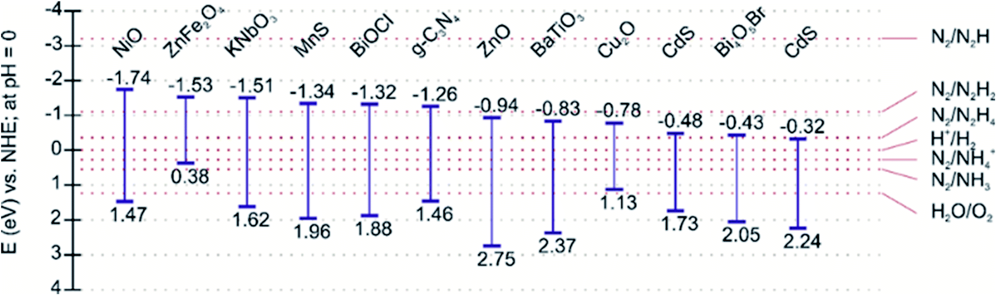 | ||
| Fig. 3 Band edge positions of representative photocatalysts reported for considerable nitrogen fixation photoactivity. | ||
One of the generally long-standing issues in single-component photocatalysts is the recombination of charge carriers before they are transferred to the surface to participate in the reduction and oxidation reactions. This issue particularly exacerbates photocatalytic N2 fixation because of the reduced availability of free electrons to drive the reduction of adsorbed N2 molecules, resulting in sluggish kinetics. Moreover, the electron energy cannot be easily regulated to drive the highly energy-intensive N2 reduction reaction, in the case of single-component photocatalysts. These restrictive factors, in turn, lead to low N2 fixation activities for most of the reported photocatalysts, around 100 μmol g−1 h−1, far below any industrial significance. Moreover, the photocatalytic efficiency is limited due to the wide bandgap of the majority of semiconductors that cannot be photoexcited by visible light. One of the most investigated single-component photocatalysts possessing superior photoactivity to date is TiO2, but it is photoactive only in the ultraviolet solar spectrum. It should be noted that UV light accounts for only a minor portion of the solar spectrum while visible light comprises almost 45% of the solar spectrum. Therefore, pristine TiO2 and other similar wide bandgap semiconductors suffer from low photoactivity.54 To overcome the above-mentioned issues associated with single-component photocatalysts, several modification strategies have been developed over recent years, such as the formation of heterojunctions, noble metal deposition, surface modification, doping, and defect engineering.55 Among these approaches, the construction of heterojunctions is currently the most effective strategy for improving spatial charge separation and provision of visible light-harvesting.34 A brief description of heterojunction types and their associated advantages over conventional photocatalytic systems are given in the following section.
2.4 Heterojunction-based photocatalyst charge transfer mechanism
In terms of the formation of heterojunction-based photocatalytic nitrogen fixation, currently, two different types, i.e., Z-scheme and type-II (p–n) heterojunction are being used. These two commonly used heterojunctions possess identical valence and conduction band alignment but differ in the photogenerated charge transfer route. The type II and Z-scheme consist of two semiconductors joined together in a tandem assembly, in which one semiconductor acts as a reducing component while the other semiconductor acts as an oxidising component. In the case of type-II heterojunction, the reducing component is n-type, while the oxidising component is p-type, whereas in the Z-scheme, the reducing component is usually labelled PC I, and the oxidising component is labelled PC II. The type-II heterojunction is characterised by the n-type component having lower conduction band (CB) and valence band (VB) positions than the p-type component. In type-II heterojunction, electrons are transferred from the CB of the p-type component to the CB of n-type, whereas holes are transferred from the VB of the n-type component to the VB of the p-type component, as shown in Fig. 4a. Therefore, the type-II heterojunction charge transfer mechanism allows the separation of photogenerated electrons and holes, resulting in the inhibition of charge recombination, which greatly enhances the photoactivity. However, as can be seen from Fig. 4a, the type-II charge carrier pathway results in the preservation of electrons and holes with smaller redox ability, which is unfavourable for high thermodynamic requirements associated with the nitrogen fixation process. To overcome this issue, the Z-scheme heterojunction inspired by the natural photosynthesis process endows suppression of charge carriers as well as preservation of high redox potential charge carriers.56 The Z term is used to emphasise the charge transfer pathway, which closely resembles the shape of the letter Z. The Z-scheme band alignment is similar to the staggered type-II band alignment but differs in the charge transfer route, i.e., photoexcited electrons of PC II recombine with holes of PC I, as shown in Fig. 4b. This charge transfer mechanism thus allows the preservation of highly reducing electrons and oxidising holes in separate phases, which shall contribute to sustaining photocatalytic driven nitrogen fixation via the reduction route, while the oxidising holes must be consumed by another substrate to maintain the charge balance. A clever choice of the substrate sacrificed for oxidation may enhance the overall balance of the entire nitrogen fixation process. Moreover, the formation of a heterojunction with semiconductors having modified bandgaps induces band bending at the junction interface. This band bending results in the formation of an internal electric field, which drives the oppositely charged electrons and holes in opposite directions resulting in spatial separation of charge carriers.57 Thus, heterojunction-based photocatalysts engender visible light-harvesting, as narrow bandgap photocatalysts can be used to construct oxidation and reduction components separately, a highly desired goal for sustainable photocatalytic nitrogen fixation.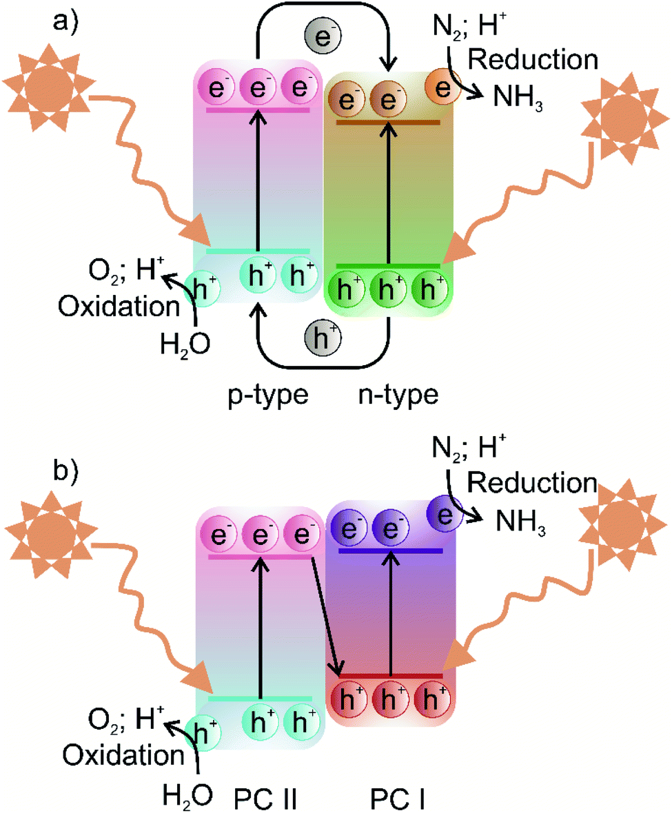 | ||
| Fig. 4 Schematic illustration of the photocatalytic process of (a) type-II heterojunction and (b) Z-scheme photocatalysts. | ||
2.5 Photocatalytic nitrogen reduction reaction
Since direct nitrogen oxidation is a kinetically and thermodynamically highly challenging reaction, only a minor portion of the oxidatively fixed nitrogen is obtained by lightning bolts and volcanic activities. Furthermore, no organism has developed any enzyme capable of oxidative nitrogen fixation, further substantiating N2 oxidation unfeasibility.58 Thus, in nature and for industrial requirements, nitrogen fixation is always carried out via the nitrogen reduction reaction (NRR). Photocatalytic NRR is initiated when N2 molecules are trapped and activated on the photocatalyst surface and react with the photogenerated electrons and protons in the electrolyte to generate NH3 and other nitrates. One critical issue in the current photocatalytic NRR is the low selectivity of the NRR due to the competing hydrogen evolution reaction (HER).31 The standard equilibrium redox potential for the NRR and HER is +0.092 V and 0 V, respectively, on the reference scale of NHE.59 This implies that the thermodynamic favourability of the HER, which is a two-electron transfer process, is greater than the six-electron transfer NRR. Moreover, the large energy gap between the HOMO (σ-2p) and anti-bonding LUMO and the low proton affinity of dinitrogen molecules increase the kinetic unfavourability of NRR to occur.60 Therefore, a careful selection of electrolytes that suppress proton transfer and with increased solubility of N2 would also greatly enhance the overall NRR efficiency.61 Additionally, since the NRR only involves the reduction component of the photocatalyst, sacrificial agents, such as EDTA and methanol, are typically used in the reaction medium for scavenging holes to prevent them from combining with the electrons, and thus inhibiting charge carrier recombination.62
Generally, the heterogeneous photocatalytic NRR mechanism is believed to be the same one evolved by the nitrogenase enzyme, yet without the H2 formation as follows:63,64
| N2 + 6e− + 6H+ → 2NH3, E0 = +0.55 V vs. NHE | (6) |
The first step in the NRR process is based on the proton-coupled electron transfer (PCET) mechanism, in which N2H species are formed on the surface of the catalyst according to eqn (7).
| N2 + H+ + e− ⇔ N2H, E0 = −3.2 V vs. NHE | (7) |
Eqn (7) shows that the formation of N2H requires a very high negative reduction potential. In the NRR, other intermediates, hydrazine (N2H4) and diazene (N2H2) are also formed which participate in four and two-electron transfer reactions, respectively, according to eqn (8) and (9).
| N2 + 4H+ + 4e− → N2H4(g), E0 = −0.36 V vs. NHE | (8) |
| N2 + 2H+ + 2e− → N2H2(g), E0 = −1.10 V vs. NHE | (9) |
Currently, the mechanism of the NRR is understood to be of two different types, i.e., dissociative and associative mechanism.45 In the dissociative NRR mechanism, the triple NN bond of the N2 molecule is initially cleaved and then proceeds by the hydrogenation reaction, with the final formation of NH3 molecules, as shown in Fig. 5.49 The HB process reaction mechanism is believed to proceed via the dissociative mechanism, in which the reaction between N and H atoms takes place after the cleavage of N2 and H2 molecules (Fig. 5a). In contrast to the dissociative mechanism, the associative mechanism proceeds via initial hydrogenation of N2 and subsequent cleavage of NN bonds and NH3 formation. Moreover, hydrogenation in the associative mechanism has two possible pathways, i.e., the distal and the alternating pathway (Fig. 5b and c). In the distal pathway, the addition of protons to nitrogen atoms occurs away from the catalyst surface, while the alternative pathway proceeds via the protonation of two nitrogen atoms before one N atom is converted to NH3.49 Since solar radiation cannot provide the high energy required to break the highly stable NN bonds, any photofixation process shall occur via the associative mechanism, similar to how BNF proceeds in the presence of the nitrogenase enzymes. In summary, key factors for improving the overall efficiency of the photocatalytic NRR are capturing of N2 molecules at the photocatalyst surface, the extension of light-harvesting to the visible spectrum, and the spatial separation of photogenerated charge carriers.
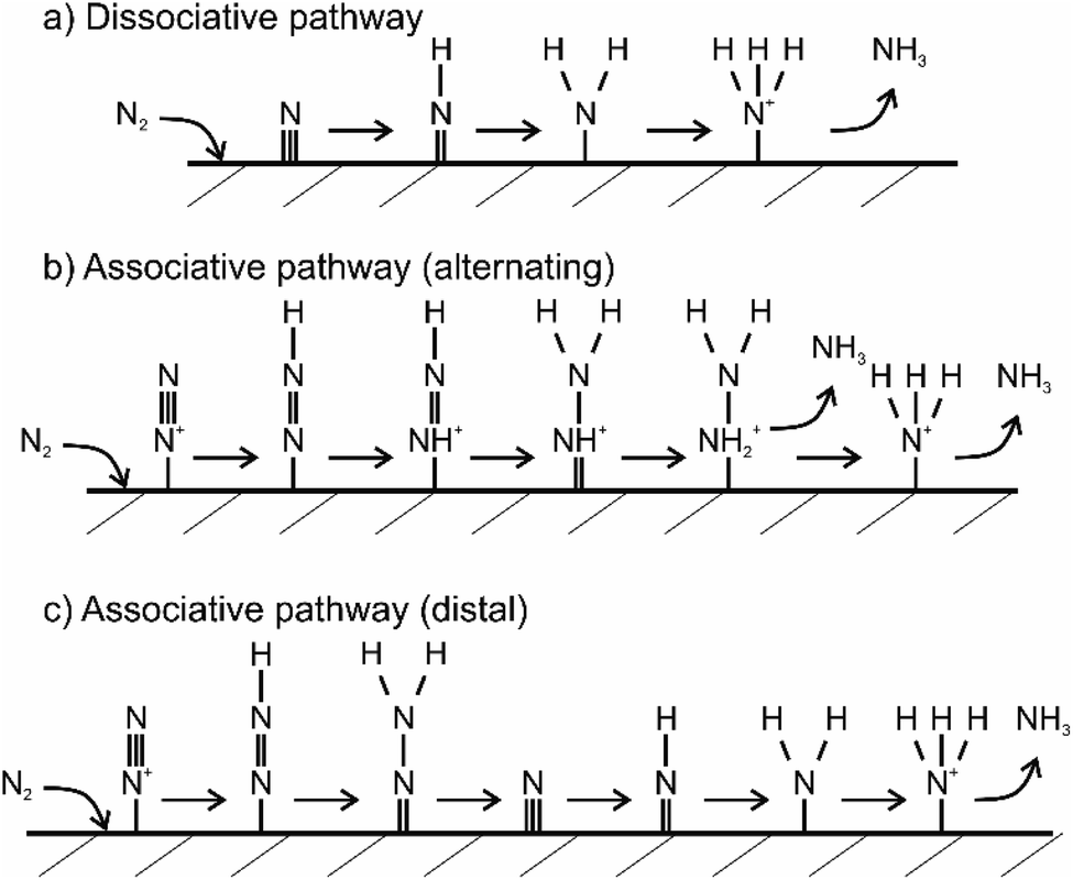 | ||
| Fig. 5 Theoretically proposed mechanism of nitrogen fixation on a heterogeneous catalyst surface. Three mechanisms are illustrated. Figure (a) shows dissociative pathway, (b) shows alternating associative pathway and (c) shows distal associative pathway of nitrogen fixation. Adapted from ref. 53. | ||
3. Performance evaluation of photocatalytic nitrogen fixation
For any specific photocatalytic system, it is necessary to evaluate the efficiency of nitrogen fixation by directly quantifying its nitrogenous products, such as ammonia or nitrates. Usually, for photocatalytic nitrogen fixation conducted via a powdered suspension system under a specific set of operating conditions, a yield unit of μmol gcat h−1 is preferred. For immobilised photocatalytic systems, it is rather more suitable to determine the product yield per unit area of the substrate, such as μmol m−2 h−1. The photocatalytic nitrogen fixation also depends on the experimental conditions, such as light source, light intensity, gas feed composition, and photocatalyst quantity. This mandates the need for reporting all of the experimental parameters employed in the nitrogen fixation experiments, and only in the case of a similar experimental profile, profile can data be reasonably compared. Moreover, it is not suitable to compare the efficiencies when two or more different products are obtained by nitrogen fixation. Therefore, in order to reflect actual nitrogen fixation efficiency in such a case, apparent quantum efficiency (AQE) is considered more suitable, as defined by eqn (10).65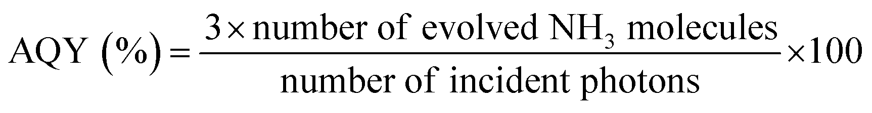 | (10) |
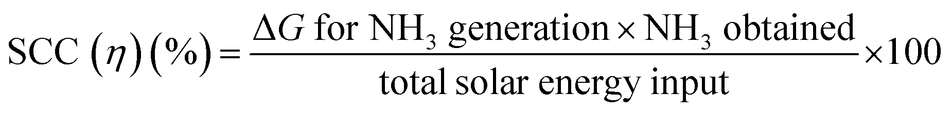
For the determination of practical suitability, the solar-to-chemical conversion (SCC) efficiency has been frequently used in most photocatalytic applications, such as water splitting and CO2 reduction. SSC quantifies the efficiency of the rate of solar to chemical energy and is defined as the ratio of generated chemical energy of NH3 to the total solar energy input, as follows:
 | (11) |
Unlike AQE, which is specific to the wavelength and light intensity, SCC encompasses the whole spectrum of solar irradiation, enabling the evaluation of feasibility for a given nitrogen fixation system. It is generally believed that a 10% SCC photocatalytic system can be implemented on a large-scale for practical purposes.66
One of the key issues affecting the practical feasibility of photocatalysis is the instability of photocatalysts over consecutive cyclic runs due to structural degradation and corrosion. Most commonly used photocatalytic materials, such as metal sulphides, copper-based materials, and zinc oxides, are susceptible to corrosion. Depending on the material, under light illumination, semiconductors can be oxidised or reduced, resulting in the decomposition of the semiconductor material and subsequent deactivation of the photocatalysts.67 For example, in the case of metal sulphides, sulphide ions (S2−) are usually oxidised by holes to form sulphate ions (SO42−) or sulphur,68 while silver-based materials are reduced to metallic Ag0 by the photogenerated electrons.69 Additionally, the reaction intermediates of the NRR can also act as a catalyst poison or occupy N2 adsorption sites, resulting in sluggish reaction kinetics. Therefore, a commercially viable photocatalyst must possess not only high efficiency but also structural stability throughout prolonged cyclic runs. The stability of a photocatalyst is usually determined by conducting several consecutive photocatalytic N2 fixation cycles and evaluating the degree of variation in the performance of each cyclic run. Photocatalytic material costs and recycling take precedence over photocatalytic activity, keeping in view the principles of green chemistry and commercial applicability. For instance, photocatalysts loaded with noble metals, such as Ag, Pd, and Pt can greatly enhance photoactivity; however, the high costs and scarcity of these metals offset such associated advantages. Recuperation of the employed photocatalysts is also essential in terms of applicability, as poor recyclability incurs additional costs and secondary pollution. The most commonly employed strategy for recycling is the immobilisation of photocatalysts on a solid support, such as thin-film glass or embedding in polymer-based nanofibers.
4. NH3 detection methods
Currently, there are no standardised procedures to detect NRR yield rate, and several methodologies have been used for the quantitative analysis of the NRR fixation products, such as NH4+, N2H4, and NO3−. Moreover in the NRR, there are some experimental caveats, as the reaction yield is still very low and prone to erroneous quantification due to external N2, NH3, other nitrogenous contamination, human breath, and equipment.70 This entails establishing a reliable and accurate experimental detection protocol for the evaluation of NH3 production yields, and several such protocols have been suggested in the literature.71–74 The significance of following improved experimental practices in the NRR field is highlighted from the study conducted by Choi and his co-workers. In their analysis of 127 recent studies on the NRR, all reported studies followed unreliable NH3 detection experimental protocols, prone to erroneous results.71 Therefore, a rigorous experimental protocol for the determination of NRR reaction yield is suggested in Fig. 6.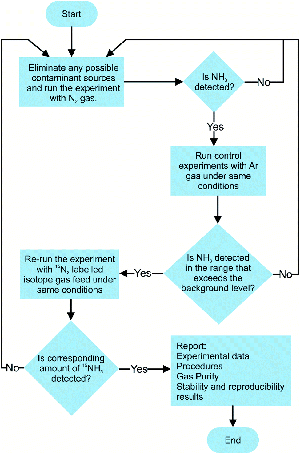 | ||
| Fig. 6 Suggested experimental protocol for conducting nitrogen fixation performance evaluation. | ||
Currently, for qualitative and quantitative analysis, several methods for the evaluation of NRR yield products are available that broadly fall under categories such as gas sensing, spectrophotometry, chromatography, and nuclear magnetic resonance (NMR) spectroscopy.75–77 The detection of ammonia via gas sensing has attracted the interest of many researchers, as these devices are capable of delivering reliable and accurate detection of volatile organic compounds. However, focus has been mainly on developing portable gas sensors to detect toxic indoor chemicals, including NH3.78,79 Various types of ammonia gas sensors exist, each differing in the gas sensing mechanism, such as chemicapacitive, surface acoustic wave, electrochemical, optical fibre, and quartz crystal microbalance-based gas sensors.78 The typical detection limit of these gas sensors usually ranges from 25 ppb to 100 ppm. Nevertheless, a suitable gas sensing technique must have a high degree of reliability for practical significance towards NH3 detection. The most challenging aspect is addressing the effect of relative humidity on gas sensors, which increases the sensing response, resulting in subsequent alteration in sensitivity, response, and recovery time. Borsdorf and his co-workers80 recently developed an automated system for the evaluation of NH3 and H2S under humid conditions. By switching between high and low humidity, a mathematical relationship was developed to measure and offset the expected spikes in the voltage signal. The effectiveness of the developed model was evaluated and it showed reasonable reliability (R2 > 97%) and detection limit (10 ppm), paving the way for their further applicability in NH3 detection. Among the above-mentioned NH3 detection methods, Nessler's reagent (K2HgI4) method is the most widely used for the analytical determination of NH3 owing to its simplicity, operational ease, and cost. In a typical Nessler's reagent analysis, an alkaline solution of Nessler's reagent is allowed to react with NH3, resulting in a reddish brown complex (Hg2ONH2I) with an absorbance peak of 420 nm. The amount of light absorbance of the Hg2ONH2I complex solution is proportional to the NH3 concentration in the absence of other impurity ions. Thus, this enables precise NH3 detection via UV-vis absorbance spectroscopy at 420 nm. However, the handling of Nessler's reagent should be undertaken with great precaution since Hg ions are toxic, and the limited shelf life of 3–4 weeks increases the risk of mercury poisoning. Use of indophenol blue is another colourimetric method for the detection of the presence of ammonia via Berthelot's reagent, an alkaline solution of carbolic acid and hypochlorite (OCl−). In this reaction, NH3 initially reacts with OCl− ions to form monochloramine (NH2Cl), which further reacts with two carbolic acids to form a blue-coloured indophenol dye. Similar to Nessler's reagent, NH3 concentration is determined by evaluating the absorbance of the indophenol dye at λ = 640 nm. Berthelot's reagent has some associated shortcomings, as indophenol dye gradually photodegrades and is prone to undesirable reactions with other amine groups present in the solution. It has been recently reported that spectroscopic NH3 detection accuracy is affected by the pH and the presence of sacrificial agents. One case study by Gao et al. reported on the presence of sacrificial agents, usually employed in photocatalytic nitrogen fixation to inhibit charge carrier recombination, resulting in the formation of carbonyl-based compounds.81 The presence of these carbonyl compounds led to additional light absorbance, thus skewing the actual NH3 concentration. To overcome the inherited drawbacks associated with the spectroscopic NH3 detection methods, ion chromatography (IC) is generally preferred as the interference due to pH variation and the presence of sacrificial agents can be easily avoided. IC measures the concentration of ionic species by separating them on the basis of interaction with a resin. IC is generally used to detect NH4+ ions, which is the main product of nitrogen fixation in aqueous solutions.82 IC detection analysis provides high sensitivity (∼1–10 μg L−1) and short time intervals for subsequent analysis of the samples. In one reported study, Zhang et al. investigated the comparative accuracy and limitations of the NH3 detection methods described above. It was observed that in alkaline or neutral solutions with NH3 concentration lower than 500 μg L−1, both indophenol and Nessler's reagent offered reasonable NH3 detection accuracy; however, at higher concentrations and under acidic conditions, only IC and Nessler's reagent were found to be suitable for NH3 detection.75 A summarised schematic illustration of NH3 detection methods is given in Fig. 7.
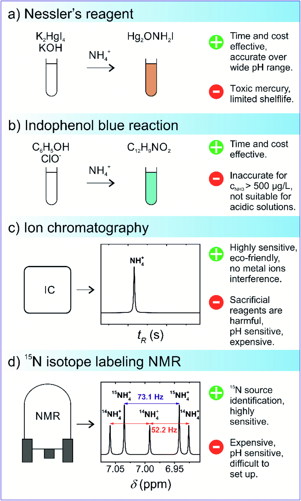 | ||
| Fig. 7 Schematics of the commonly used ammonia detection methods: (a) Nessler's reagent, (b) indophenol blue reaction, (c) ion chromatography, and (d) isotope-sensitive NMR. | ||
In addition to a careful selection of the NH3 detection method, it is imperative to conduct control experiments to avoid false positives and distinguishing the actual source of nitrogen fixation via15N2 isotope labelling.72 The 15N2 isotope labelling experiment for ammonia detection uses isotopically labelled 15N2 as a feed gas for N2 reduction; the amount of 15NH3 produced is then evaluated. In this experiment, the amount of 15NH3 produced should be quantitatively similar to 14NH3 when 14N2 as a gas feed is used by an isotope-sensitive method. Currently, nuclear magnetic resonance is the most accurate quantitative and qualitative technique that overcomes the limitations associated with conventional NH3 detection techniques. For example, the presence of cationic species, ammonium, and its isotopologue 15NH4+ can alter the accuracy of the IC detection method since the distinction cannot be easily made between ionic species due to the similar m/z ratio.83 However, in 1H NMR, a subtle distinction can be made between nitrogen isotopes because NMR scalar coupling and molecular interactions between 1H and 15NH4+ split the 1H resonance into a doublet signal with a spacing of 73 Hz, while resonance signals obtained from the 1H and 14NH4+ coupling are split into a relatively sharp triplet with a spacing of 52 Hz.84,85 The respective quantitative analysis of both 14NH4+ and 15NH4+ isotopes can be carried out from the integrated peak areas. Kolen et al. recently reported83 on a facile and relatively cost–time effective method based on the 1H NMR technique for ammonia detection over a wide pH range with high sensitivity (<2%). The technique employed the use of paramagnetic Gd3+ ions and resulted in cost and time reduction as compared to 15N2 control experiments. The proposed method exhibited good linearity (R2 = 0.999), implying its great potential for the isotopic detection of nitrogen fixation products.
5. Material designing for boosting photocatalytic nitrogen fixation
In order to optimise the selectivity and the photocatalytic efficiency of the nitrogen fixation process, careful screening of photoactive materials is imperative. Over the last two decades, several strategies have been used for optimising the crystal structure, morphology, surface area, and alteration of electronic and optical properties. It is worth noting that these modification strategies, usually reported for single material photocatalysts can also be used for improving the efficiency of the individual components in a constructed heterojunction. It is generally accepted that the adsorption and activation of N2 molecules on the active sites available at the catalyst surface is the rate-determining step. Therefore, current research efforts are dedicated to introducing structural defects in photocatalysts capable of capturing N2 molecules for the reaction to proceed. Experimental results have shown that bulk defects usually act as charge recombination centres and thus limit the photocatalytic efficiency by restricting the charge diffusion to the surface. Conversely, surface defects are known to serve as adsorption sites for the reactant molecules. The key factor for promoting the heterojunction NRR is the provision of strong chemisorption of N2 molecules and weak binding of its intermediates onto the catalyst surface. A firm binding of NRR intermediates increases the likelihood of catalyst poisoning and in turn, creates a volcano-like trend between the bond energy and catalytic activity.86 Additionally, the oxygen molecules present in the aqueous electrolyte can also preferentially occupy the active sites, consequently impacting the efficiency of catalysts.Introduction of anionic (C, N and S) vacancies, one of the most commonly introduced defects, can facilitate the NRR by providing chemisorption and electron trapping sites. These anionic vacancies act as active sites for N2 adsorption owing to the following key points: (i) the elements in the vicinity of an anion vacancy have a strong tendency to bind with N2, and (ii) provision of high electron density for N2.87 Evidently, for the nitrogen fixation process, materials possessing nitrogen vacancies (NVs) seem ideal for capturing N2 molecules owing to the same atomic size and shape. Graphitic carbon nitride (g-C3N4) has been widely researched as a photocatalyst, and there are several reported studies in the literature that show superior performance mainly due to the presence of NVs. These NVs are introduced by various synthesis methods, such as calcination in a N2 atmosphere, microwave treatment, metal doping, and the dissolve–regrowth method.88,89 An early study conducted by Dong et al. confirmed that the introduction of NVs in g-C3N4 results in imparting visible light range to the photocatalytic nitrogen fixation, despite a slight enlargement in the bandgap relative to the bare g-C3N4 due to the quantum confinement effect.90 It was observed that compared to the pristine g-C3N4 sample, which exhibited no photoactivity for N2 fixation, vacancies induced g-C3N4 generated a nitrogen photofixation rate of 1.24 mmol h−1 g−1. Additional tests attributed the nitrogen fixation ability of g-C3N4 to the presence of NVs via the formation of chemisorption sites for N2 activation.90 Besides NVs, oxygen and sulphur vacancies have also gained considerable interest due to their superior performance in various photocatalytic applications and have also been investigated recently for N2 fixation applications. In another reported study,91 Jin et al. prepared an oxygen vacancy (OV) rich heterojunction (Bi2MoO6/OV-BiOBr) capable of delivering an optimised NH3 yield rate of 90 μmol g−1 h−1, compared to the 3.0 μmol g−1 h−1 rate generated by the pristine Bi2MoO6 samples. Room temperature electron paramagnetic resonance spectroscopy revealed a strong EPR signal at g = 2.003, which was assigned to the electrons captured by the OVs, while Bi2MoO6 exhibited no EPR signal, implying the absence of OVs. The enhanced photoactivity under visible light without any rare earth metal and sacrificial agent was primarily achieved due to the role of the OVs.91 Recently, it has been reported in a few theoretical and experimental studies that OV defects in CuO decrease the absorption energy for NO3− reactants. On the other hand, Cu metal increases the selectivity for NH3 formation as it can bind with *NO, while no binding affinity is observed for *H species.92,93
A fundamentally different strategy that can be applied to the heterostructured photocatalysts to enhance photoactivity is the incorporation of nano-sized metallic particles to exploit plasmonic effects. Plasmonic nanoparticles impart optimised light absorption via different mechanisms, such as hot electron injection, localised electromagnetic field, and plasmon-induced resonance energy transfer (PIRET).94 The most commonly used plasmonic nanoparticles are noble metals (Ag and Au) due to their strong localised surface plasmonic resonance (LSPR) effect.95 In the reported literature on plasmonic photocatalysts, the enhancement in the photoactivity is usually associated solely with the charge transfer from the metal nanoparticle to the photocatalyst surface and the formation of the Schottky barrier. However, a comprehensive study by Souza et al. on pristine, Ag, and Au-based Ti2O revealed that the fundamental mechanism involved in the superior performance of plasmonic photocatalysis is the local enhancement of electromagnetic field. This localised increase in intensity results in the excitation of electrons from the LSPR nanoparticles to the CB of the photocatalyst positioned slightly above the LSPR excitation band. These excited LSPR electrons are responsible for indirect excitation of Ti2O, generation of e−/h+ pairs and thereby enhancing the photoactivity.96 Recently, Gao et al. reported on the construction of an Ag/AgI-δ-Bi2O3 photocatalyst by a hydrothermal and in situ photo deposition method, which was capable of a superior NH3 generation rate of 420 μmol L−1 g−1 h−1. The enhanced nitrogen photofixation under visible light and without any sacrificial agent was mainly due to the oxygen vacancies and plasmonic effect, i.e., Ag nanoparticles releasing free electrons that possess high energy states after the absorption of photons and their subsequent migration to the δ-Bi2O3 surface due to the LSPR effect.97
6. Type-II heterojunction photocatalytic systems
Constructing a type-II based heterojunction is one of the most commonly used strategies for extending visible light-harvesting and has been extensively investigated in several photocatalytic applications, such as water splitting, CO2 reduction, pollution abatement as well as nitrogen fixation. An efficient type-II photocatalyst must possess an external surface component capable of visible light-harvesting while simultaneously satisfying the band alignment and interfacial compatibility of the two components. Moreover, the interface at the junction also plays a key role in enhancing the quantum efficiency of the photocatalyst due to the lattice mismatch of two different components. The lattice mismatch and strain introduce structural defects and an induced electric field, which trap the photogenerated charge carriers, preventing futile charge recombination.98 Therefore, great attention should be paid when selecting the components that fulfil the prerequisite requirements for the optimal design of type-II photocatalysts. Some recent literature reports on type-II heterojunctions for nitrogen fixation are summarised in Table 1. Fayun Li and his co-workers reported99 a novel photocatalyst g-C3N4/ZnSnCdS that exhibited an excellent nitrogen fixation rate of 7.543 mg L−1 h−1 g−1 (58.72 μmol L−1 g−1 h−1) under visible light. Experimental results showed strong synergistic coupling of both components, while EPR spectroscopy revealed the presence of abundant sulphur vacancies on the ZnSnCdS component. N2-TPD chemisorption of ZnSnCdS exhibited two strong intensity peaks at ∼120 °C and 270 °C, attributed to the physical adsorption and chemisorption of N2 molecules, respectively.| Catalyst | Catalyst dose (mg) | Synthesis method | Light source and/or filter | Activity | NH3 detection method | Ref. |
|---|---|---|---|---|---|---|
| NiS/KNbO3 | 5 | Hydrothermal | 300 watt Xe lamp | 155.6 μmol L−1 g−1 h−1 | Nessler's reagent | 101 |
| g-C3N4/BiMoO6 | 4 | Reflux assisted | 500 W Xe lamp with a 420 nm cut-off filter, I = 100 mW cm−2 | 3271 μmol L−1 g−1 | Nessler's reagent | 100 |
| NiO/KNbO3 | 10 | Photodeposition | 300 watt Xe lamp | 470.6 μmol g−1 h−1 | Nessler's reagent | 102 |
| Cu2O/SnS2/SnO2 | 100 | Solvothermal | 300 watt Xe lamp | 372 μmol g−1 h−1 | Nessler's reagent | 103 |
| CeO2–BiFeO3 | 20 | Hydrothermal | 300 watt Hg lamp | 117.77 μmol g−1 h−1 | — | 104 |
| ZnIn2S4/BiOCl | 200 | In situ solvothermal | 300 W Xe lamp with a 420 nm cut-off filter | 14.6 μmol g−1 h−1 | Nessler's reagent | 105 |
| Ag/AgI-δ-Bi2O3 | 200 | Hydrothermal-photodeposition | 400 W Xe lamp with a 420 nm cut-off filter | 420 μmol L−1 g−1 h−1 | Ion chromatography | 97 |
| AgCl/δ-Bi2O3 | 200 | Hydrothermal | 400 W Xe lamp with a 400 nm cut-off filter | 606 μmol g−1 h−1 | Nessler's reagent | 106 |
| g-C3N4/ZnSnCdS | 200 | Hydrothermal | 250 W Na lamp | 7.543 mg L−1 h−1 g−1 | Nessler's reagent | 99 |
| g-C3N4/ZnMoCdS | 200 | Hydrothermal post-treatment | 250 W Na lamp | 2.5 mg L−1 h−1 g−1 | Nessler's reagent | 107 |
| Cu2O/CN | 20 | Solvothermal | 300 W Xe λ > 420 nm | 10 μmol h−1 | Indophenol blue method | 108 |
| PANI@ZnIn2S4 | 50 | Hydrothermal | 300 W Xe λ > 420 nm | 290 μmol L−1 h−1 | Nessler's reagent | 109 |
| Bi2MoO6/OV-BiOBr | 30 | Solvothermal | 300 W Xe λ > 420 nm | 90.7 μmol g−1 h−1 | Nessler's reagent | 91 |
Additionally, the PL spectra of ZnSnCdS in a N2 atmosphere displayed weaker peak emissions as compared to the other samples, implying increased electronic transfer to the adsorbed N2 species. Therefore, the g-C3N4/ZnSnCdS heterojunction visible light nitrogen fixation rate was ascribed mainly to the chemisorption of N2 species via sulphur vacancies and strong electronic coupling. In another reported study by Ghosh et al., g-C3N4/BiMoO6, a type-II photocatalyst fabricated via a facile reflux assisted method, exhibited substantial visible light nitrogen reduction. The photocatalyst ammonia generation rate of 3271 μmol L−1 g−1 at pH 7 was achieved due to the optimised spatial charge separation and electronic coupling of both reduction and oxidation components.100 However, pH variations resulted in the suppression of the NRR rate due to the increased concentration of H+ ions and oxidation of ammonium ions.100
7. Z-scheme photocatalytic systems
Z-scheme-based photocatalysts provide superior photoactivity owing to their ingenious charge mechanism, i.e., simultaneous provision of high redox potentials and visible light-harvesting. Therefore, compared to type-II heterojunctions, the drawback of overall loss in redox potential can be overcome. This enables much higher suppression of charge recombination and consequently higher photoactivity in water splitting with a theoretical attainable efficiency of 40% compared to 30% of activity, which can be achieved via single-component photocatalysts.110 Some recently investigated Z-scheme heterojunctions for nitrogen fixation are listed in Table 2. Shihai et al. reported on an all-solid-state Z-scheme photocatalytic system based on 3,4-dihydroxybenzaldehyde functionalised Ga2O3/g-C3N4, fabricated via Schiff base chemistry.111 A superior visible light nitrogen fixation was achieved, reaching as high as 112.5 μmol L−1 g−1, sufficiently higher than single-component g-C3N4. Investigation into the photocatalytic mechanism suggested that the aromatic ring 3,4-dihydroxybenzaldehyde acted as an electron mediator at the Ga2O3 and g-C3N4 interface while high oxidising potential ensured the production of hydroxyl radicals. The nitrogen fixation proceeded via oxidation of methanol to CO2− and its reaction intermediates and subsequent reduction of N2via CO2− radicals. It is well known that the introduction of defects is favourable for enhancing photoactivity by trapping electron–hole pairs and increasing the propensity of charge carriers to participate in the surface reaction.112 Considering the specificity of the nitrogen reduction reaction, the introduction of nitrogen vacancies into the crystal lattice of the photocatalyst could be useful for trapping and activating N2 molecules. In one reported study, Guang et al. prepared a g-C3N4/Ag2CO3 photocatalytic system based on the Z-scheme mechanism, in which nitrogen vacancies were introduced via dissolution of nitrogen in ammonium ion solution.113 The catalyst displayed a superior N2 production rate of 11 mg L−1 h−1 gcat−1, under proportionally equal concentrations of N2 and O2. Experimental results showed that the nitrogen photofixation proceeded via a two-path mechanism. Initially, nitrogen molecules were trapped and activated by the nitrogen vacancies, and subsequent reduction of trapped molecules via hydrogen ions resulted in the formation of ammonium ions. In the second reaction pathway, oxygen molecules were reduced to form H2O2, which undergo further reduction to form OH radicals. These radicals reacted with methanol to generate CO2− radicals, which further reduced the N2 molecules to NH3 with the release of CO2−. The high rate of N2 photofixation in a mixed atmosphere was attributed to the general favourability of the charge transfer between O2 molecules and the catalyst. Recently, metal–organic frameworks (MOFs) have also attracted great interest for photocatalysis, mainly due to their high porosity and surface area, enabling a large number of active sites for the reaction to proceed. However, MOFs exhibit poor photocatalytic activity when utilised as a single-component photocatalyst. Therefore, MOFs are usually combined with other photoactive materials to enhance their photoactivity. In one relevant reported case, Ding et al. synthesised nitrogen defect-containing g-C3N4 films with MOF-74, exhibiting the characteristic of the Z-scheme.114| Catalyst | Catalyst dose (mg) | Synthesis method | NH3 detection method | Light source and/or filter | Activity | Ref. |
|---|---|---|---|---|---|---|
| g-C3N4/FeOCl | 4 | Calcination and hydrothermal | Nessler's reagent | 500 W Xe lamp | 3800 μmol L−1 g−1 | 115 |
| YF3:Sm3+/ATP | 50 | Hydrothermal | Nessler's reagent | 400 W Xe lamp with a 420 nm cut-off filter | 41.2 mg−1 L−1 | 116 |
| SiW9Co3/PDA/BWO | 150 | Hydrothermal and polymerization | Nessler's reagent, indophenol, ion chromatography, and 1H NMR | 400 W Xe lamp with a 420 nm cut-off filter, I = 400 mW cm−2 | 52.67 μmol gcat−1 h−1 | 117 |
| MOF@defective C3N4 film | 10 | Sol–gel | Nessler's reagent | 300 W Xe lamp with a 400 nm cut-off filter | 2.32 mmol g−1 h−1 | 118 |
| g-C3N4/ZnFe2O4 | 100 | Solid state synthesis and solvothermal | Nessler's reagent | 500 W Xe lamp with a 420 nm cut-off filter | 1.02 μmol L−1 min−1 | 119 |
| AgBr/Bi4O5Br2 | 5 | Hydrothermal and ion exchange process | Nessler's reagent | 300 W Xe lamp (PLS-SXE300C) | 179.4 μmol L−1 g−1 h−1 | 120 |
| g-C3N4/Ag2CO3 (with N vacancy) | 10 | Self-sacrificial | Nessler's reagent | 250 W Xe lamp (400–800 nm) | 11 mg L−1 h−1 gcat−1 | 113 |
| g-C3N4/Ni3V2O8 | 4 | Hydrothermal | Nessler's reagent | 500 W Xe lamp with a 420 nm cut-off filter, I = 100 mW cm−2 | 3355 μmol L−1 g−1 | 121 |
| TiO2/ZnFe2O4 | 5 | Solvothermal method and calcination | Nessler's reagent | 250 W Xe lamp with a 420 nm cut-off filter | 1.48 μmol L−1 min−1 | 122 |
| AgInS2/MXene | 20 | Hydrothermal | Indophenol reagent | 300 W Xe lamp with a 400 nm cut-off filter | 38.8 μmol g−1 h−1 | 123 |
| CeCO3OH/g-C3N4/CeO2 | 30 | Self-sacrificial | Nessler's reagent | 500 W Xe lamp | 1.16 mM g−1 h−1 | 124 |
| LnCO3OH/g-C3N4 | 30 | Hydrothermal and self-sacrificial | Nessler's reagent | 500 W Xe lamp | 8.91 mM g−1 h−1 | 125 |
| Ga2O3-DBD/g-C3N4 | 2 | Thermal polymerization | Nessler's reagent | 500 W Xe lamp | 112.5 μmol L−1 h−1 | 111 |
| LaCoO3:Er3+/ATP | 4 | Sol–gel | Nessler's reagent | 300 W Xe lamp with a 420 nm cut-off filter | 71.5 μmol g−1 h−1 | 126 |
| MnO2−x/g-C3N4 | 50 | Hydrothermal and calcination | Nessler's reagent | 300 W Xe lamp | 225 μmol g−1 h−1 | 127 |
| g-C3N4/Mg1.1Al0.3Fe0.2O1.7 | 200 | Hydrothermal | Nessler's reagent | 250 W Xe lamp (400–800 nm) | 7.5 mg L−1 h−1 gcat−1 | 128 |
| CoFe2O4/g-C3N4 | 20 | Decomposition–thermal polymerization | Nessler's reagent | 300 W Xe lamp with a 400 nm cut-off filter | 313 mg L−1 gcat−1 | 129 |
| W18O49/g-C3N4 | 200 | Hydrothermal | Nessler's reagent | 300 W and 200 W Xe lamp with >800 nm and <800 nm filters | 2.6 mg L−1 h−1 gcat−1 | 130 |
| g-C3N4/Cu2(OH)2CO3 | 100 | In situ self-sacrificial | Nessler's reagent | 300 W and 200 W Xe lamp with >800 nm and <800 nm filters, respectively | 14 mg L−1 h−1 gcat−1 | 131 |
The experimental results showed that the pristine nano-MOF-74 did not have visible light photoactivity, while the thin-film g-C3N4 possessed low photoactivity. When both the nano-MOF-74 and thin-film g-C3N4 were used in a![[thin space (1/6-em)]](https://www.rsc.org/images/entities/char_2009.gif) tandem assembly, a two-fold increase in the photoactivity was reported, indicating that MOFs resulted in the provision of highly photoactive sites for the photocatalytic reaction to take place. Finally, when nitrogen defects were introduced into the nano-MOF-74 and the thin-film supported g-C3N4, it resulted in a two-fold increase in the photoactivity of pure g-C3N4. The enhanced photoactivity of 2.32 mmol g−1 h−1 was attributed to the high porosity and surface area of MOFs. Moreover, the trapping of nitrogen molecules via nitrogen vacancies resulted in the activation and reduction of bond energy for the cleavage of the NN bond. In another reported study conducted by Liang et al., a W18O49/g-C3N4 photocatalyst was prepared, capable of delivering a full visible light spectrum N2 photofixation rate of 2.6 mg L−1 h−1 gcat−1. The superior photocatalytic NH3 yield rate was attributed to the coherent oscillations of the surface electrons induced by the oxygen vacancies present in W18O49. Optical investigations showed that the W18O39 component imparted light-harvesting in the whole visible spectrum and the provision of ample photogenerated electrons to recombine with the holes present in the g-C3N4. The reported catalyst also displayed excellent photostability over an operational duration of 40 h.
tandem assembly, a two-fold increase in the photoactivity was reported, indicating that MOFs resulted in the provision of highly photoactive sites for the photocatalytic reaction to take place. Finally, when nitrogen defects were introduced into the nano-MOF-74 and the thin-film supported g-C3N4, it resulted in a two-fold increase in the photoactivity of pure g-C3N4. The enhanced photoactivity of 2.32 mmol g−1 h−1 was attributed to the high porosity and surface area of MOFs. Moreover, the trapping of nitrogen molecules via nitrogen vacancies resulted in the activation and reduction of bond energy for the cleavage of the NN bond. In another reported study conducted by Liang et al., a W18O49/g-C3N4 photocatalyst was prepared, capable of delivering a full visible light spectrum N2 photofixation rate of 2.6 mg L−1 h−1 gcat−1. The superior photocatalytic NH3 yield rate was attributed to the coherent oscillations of the surface electrons induced by the oxygen vacancies present in W18O49. Optical investigations showed that the W18O39 component imparted light-harvesting in the whole visible spectrum and the provision of ample photogenerated electrons to recombine with the holes present in the g-C3N4. The reported catalyst also displayed excellent photostability over an operational duration of 40 h.
8. Future challenges and perspectives
Rapid human population growth over the last century has resulted in several environmental and energy-related issues, among which the unsustainable production of fixed nitrogen supply is of particular importance. The Haber–Bosch process employed for over a hundred years and still today for ammonia (NH3) production requires harsh conditions and is one of the main contributors to greenhouse gases. In this regard, photocatalytic nitrogen fixation for conversion of atmospheric nitrogen to NH3 and other nitrogenous compounds under mild conditions has garnered a great deal of interest. However, currently available photocatalytic systems for nitrogen fixation are inferior in conversion efficiency due to several critical issues, such as poor visible light-harvesting, sluggish capture and activation of N2 molecules, photogenerated charge separation, and low selectivity of the nitrogen reduction reaction (NRR). Therefore, to realise an acceptable nitrogen fixation system based on photocatalysis, a rational material design for enhanced nitrogen conversion efficiency is of paramount importance. So far, heterojunction materials based on type-II and Z-scheme charge transfer routes have shown promising conversion efficiencies due to the optimised bandgap and energy band alignment, allowing spatial charge separation and visible light-harvesting. Moreover, anionic vacancies in the photocatalysts act as activation and trapping centres for N2 molecules, resulting in enhanced selectivity for the nitrogen reduction reaction. Additional modifications, such as the use of precious metals, can also significantly improve photocatalytic activity, likely due to the localised surface plasmon resonance effect. Owning to the above-mentioned modification strategies, nitrogen fixation rates have increased considerably from μmol g−1 h−1 to mmol g−1 h−1.For the realisation of achieving viable photocatalytic nitrogen fixation systems for practical purposes, special attention should be paid for improving the selectivity for the NRR. Suppression of the HER and boosting the NRR is a critical issue that must be addressed by engineering photocatalyst morphology, composition, and optical properties that favour binding affinity for N atoms over H atoms. Additionally, special attention is required to develop a standardised protocol for evaluating NH3 generation rate, as the most commonly reported spectroscopic methods, use of Nessler's and indophenol reagents, are prone to erroneous results. Therefore, we posit that researchers working on photocatalytic nitrogen reduction should aim to follow the suggested experimental protocol for evaluating nitrogen fixation rate to fulfil the criteria set for experimental reliability. Finally, a thorough mechanistic study of photocatalytic nitrogen fixation reactions is necessary to elucidate the factors involved in low nitrogen fixation efficiency. Special attention should also be paid to develop experimental and theoretical nitrogen fixation systems inspired by the biological nitrogenase enzyme, consisting of Fe, S, and Mo elements. These systems have shown the potential of achieving NH3 production under ambient conditions. Furthermore, by tailoring the chemical and physical properties of these materials, the high negative potential required for the PCET reaction can be overcome. In summary, this review provides fundamental principles of heterojunction-based photocatalytic nitrogen fixation, biological and artificial nitrogen reduction reaction mechanisms. A survey of reported heterojunction-based nitrogen fixation in the literature is given, as well as performance evaluation methodologies and parameters. Even though current photocatalytic nitrogen fixation efficiencies are far from commercial viability, progress projection in this field appears to have a high potential for success. We hope that this review provides a summary of the literature for currently investigated heterojunction-based photocatalytic nitrogen fixation systems to date, for the established and new researchers in this field.
Conflicts of interest
There are no conflicts to declare.Acknowledgements
The authors are grateful for the support by the Ministry of Education, Youth and Sports of the Czech Republic within a framework of two projects – DKRVO (RP/CPS/2020/006) and (LTT20010).References
- B. M. Hoffman, D. Lukoyanov, Z.-Y. Yang, D. R. Dean and L. C. Seefeldt, Chem. Rev., 2014, 114, 4041–4062 CrossRef CAS PubMed.
- J. E. House and K. A. House, Descriptive Inorganic Chemistry, 3rd edn, 2015 Search PubMed.
- C. C. Lee, M. W. Ribbe and Y. Hu, Met. Ions Life Sci., 2014, 14, 147–176 CAS.
- K. Rousk, P. L. Sorensen and A. Michelsen, Biogeochemistry, 2017, 136, 213–222 CrossRef CAS.
- W. H. Schlesinger and E. S. Bernhardt, in Biogeochemistry, ed. W. H. Schlesinger and E. S. Bernhardt, 4th edn, Elsevier, 2020, pp. 483–508 Search PubMed.
- D. Hao, Y. Liu, S. Gao, H. Arandiyan, X. Bai, Q. Kong, W. Wei, P. K. Shen and B.-J. Ni, Mater. Today, 2021, 46, 212–233 CrossRef CAS.
- B. Huebert, P. Vitousek, J. Sutton, T. Elias, J. Heath, S. Coeppicus, S. Howell and B. Blomquist, Biogeochemistry, 1999, 47, 111–118 CAS.
- B. S. Patil, Q. Wang, V. Hessel and J. Lang, Catal. Today, 2015, 256, 49–66 CrossRef CAS.
- C. Fúnez Guerra, L. Reyes-Bozo, E. Vyhmeister, M. Jaén Caparrós, J. L. Salazar and C. Clemente-Jul, Renewable Energy, 2020, 157, 404–414 CrossRef.
- C. Smith, A. K. Hill and L. Torrente-Murciano, Energy Environ. Sci., 2020, 13, 331–344 RSC.
- M. Capdevila-Cortada, Nat. Catal., 2019, 2, 1055 CrossRef.
- X. H. Lu and Y. Wang, Appl. Mech. Mater., 2013, 437, 1019–1022 Search PubMed.
- R. Müller, Ambio, 2021, 50, 35–39 CrossRef PubMed.
- J. W. Erisman, J. N. Galloway, S. Seitzinger, A. Bleeker, N. B. Dise, A. M. Roxana Petrescu, A. M. Leach and W. de Vries, Philos. Trans. R. Soc. Lond. B Biol. Sci., 2013, 368, 20130116 CrossRef PubMed.
- R. Daiyan, I. Macgill and R. Amal, ACS Energy Lett., 2020, 5(12), 3843–3847 CrossRef CAS.
- Manage the Nitrogen Cycle, http://www.engineeringchallenges.org/9132.aspx Search PubMed.
- D. Hao, Y. Liu, S. Gao, H. Arandiyan, X. Bai, Q. Kong, W. Wei, P. K. Shen and B.-J. Ni, Mater. Today, 2021, 46, 212–233 CrossRef CAS.
- K. H. R. Rouwenhorst, Y. Engelmann, K. van't Veer, R. S. Postma, A. Bogaerts and L. Lefferts, Green Chem., 2020, 22, 6258–6287 RSC.
- K. Mahmud, S. Makaju, R. Ibrahim and A. Missaoui, Plants, 2020, 9, 97 CrossRef CAS PubMed.
- W. H. Saputera, A. F. Amri, R. Daiyan and D. Sasongko, Materials, 2021, 14, 2846 CrossRef PubMed.
- Y. K. Mishra and R. Adelung, Mater. Today, 2018, 21(6), 631–651 CrossRef CAS.
- H. Ali, A. Guler, M. Masar, P. Urbanek, M. Urbanek, D. Skoda, P. Suly, M. Machovsky, D. Galusek and I. Kuritka, Catalysts, 2021, 11, 293 CrossRef CAS.
- G. N. Schrauzer and T. D. Guth, J. Am. Chem. Soc., 1977, 99(22), 7189–7193 CrossRef CAS.
- G. N. Schrauzer, N. Strampach, L. N. Hui, M. R. Palmer and J. Salehi, Proc. Natl. Acad. Sci. U.S.A., 1983, 80, 3873–3876 CrossRef CAS PubMed.
- J. Yang, J. Chem., 2018, 3286782 CAS.
- Y. Zhao, Y. Zhao, G. I. N. Waterhouse, L. Zheng, X. Cao, F. Teng, L.-Z. Wu, C.-H. Tung, D. O'Hare and T. Zhang, Adv. Mater., 2017, 29, 1703828 CrossRef PubMed.
- Y. Liu, L. Tang, J. Dai, J. Yu and B. Ding, Angew. Chem., 2020, 132, 13725–13729 CrossRef.
- Y. Shiraishi, S. Shiota, Y. Kofuji, M. Hashimoto, K. Chishiro, H. Hirakawa, S. Tanaka, S. Ichikawa and T. Hirai, ACS Appl. Energy Mater., 2018, 1(8), 4169–4177 CrossRef CAS.
- Y. Xue, X. Kong, Y. Guo, Z. Liang, H. Cui and J. Tian, J. Mater., 2020, 6(1), 128–137 Search PubMed.
- Y. Ren, C. Yu, X. Tan, H. Huang, Q. Wei and J. Qiu, Energy Environ. Sci., 2021, 14, 1176–1193 RSC.
- Z. Benedek, M. Papp, J. Oláh and T. Szilvási, Inorg. Chem., 2019, 58, 7969–7977 CrossRef CAS PubMed.
- J. Kibsgaard, J. K. Nørskov and I. Chorkendorff, ACS Energy Lett., 2019, 4, 2986–2988 CrossRef CAS.
- R. Manjunatha, A. Karajić, M. Liu, Z. Zhai, L. Dong, W. Yan, D. P. Wilkinson and J. Zhang, Electrochem. Energy Rev., 2020, 3, 506–540 CrossRef CAS.
- A. B. Djurišić, Y. He and A. M. C. Ng, APL Mater., 2020, 8, 030903 CrossRef.
- S. San Martín, M. J. Rivero and I. Ortiz, Catalysts, 2020, 10, 901 CrossRef.
- K. A. Brown, D. F. Harris, M. B. Wilker, A. Rasmussen, N. Khadka, H. Hamby, S. Keable, G. Dukovic, J. W. Peters, L. C. Seefeldt and P. W. King, Science, 2016, 352, 448–450 CrossRef CAS PubMed.
- R. A. Alberty, Biophys. Chem., 2005, 114, 115–120 CrossRef CAS PubMed.
- I. Djurdjevic, O. Einsle and L. Decamps, Chem.–Asian J., 2017, 12, 1447–1455 CrossRef CAS PubMed.
- M. J. Bezdek, I. Pappas and P. J. Chirik, Determining and Understanding N–H Bond Strengths in Synthetic Nitrogen Fixation Cycles, in Nitrogen Fixation. Topics in Organometallic Chemistry, ed. Y. Nishibayashi, Springer, Cham, 2017, vol. 60, DOI:10.1007/3418_2016_8.
- X.-W. Guo, S.-M. Chen, H.-J. Wang, Z.-M. Zhang, H. Lin, L. Song and T.-B. Lu, J. Mater. Chem. A, 2019, 7, 19831–19837 RSC.
- C. Xiao, H. Wang, L. Zhang, S. Sun and W. Wang, ChemCatChem, 2019, 11, 6467–6472 CrossRef CAS.
- B. Liu, A. S. Yasin, T. Musho, J. Bright, H. Tang, L. Huang and N. Wu, J. Electrochem. Soc., 2019, 166, H3091–H3096 CrossRef CAS.
- Y. Cao, S. Hu, F. Li, Z. Fan, J. Bai, G. Lu and Q. Wang, RSC Adv., 2016, 6, 49862–49867 RSC.
- J. Liu, M. S. Kelley, W. Wu, A. Banerjee, A. P. Douvalis, J. Wu, Y. Zhang, G. C. Schatz and M. G. Kanatzidis, Proc. Natl. Acad. Sci. U.S.A., 2016, 113, 5530–5535 CrossRef CAS PubMed.
- M. A. Shipman and M. D. Symes, Catal. Today, 2017, 286, 57–68 CrossRef CAS.
- M. Li, H. Huang, J. Low, C. Gao, R. Long and Y. Xiong, Small Methods, 2019, 3(6), 1800388 CrossRef.
- M. Li, H. Huang, J. Low, C. Gao, R. Long and Y. Xiong, Small Methods, 2019, 3, 1800388 CrossRef.
- J. H. Montoya, C. Tsai, A. Vojvodic and J. K. Nørskov, ChemSusChem, 2015, 8(13), 2180–2186 CrossRef CAS PubMed.
- C. J. M. van der Ham, M. T. M. Koper and D. G. H. Hetterscheid, Chem. Soc. Rev., 2014, 43, 5183–5191 RSC.
- X. Xue, R. Chen, C. Yan, P. Zhao, Y. Hu, W. Zhang, S. Yang and Z. Jin, Nano Res., 2019, 12(6), 1229–1249 CrossRef CAS.
- J. Sun, D. Alam, R. Daiyan, H. Masood, T. Zhang, R. Zhou, P. J. Cullen, E. C. Lovell, A. Jalili and R. Amal, Energy Environ. Sci., 2021, 14, 865–872 RSC.
- R. Ameta and S. C. Ameta, Photocatalysis, 1st edn, CRC Press, 2016 Search PubMed.
- X. Zhu, S. R. Castleberry, M. A. Nanny and E. C. Butler, Environ. Sci. Technol., 2005, 39, 3784–3791 CrossRef CAS PubMed.
- J. Liu, H. Zhao, M. Wu, B. Van der Schueren, Y. Li, O. Deparis, J. Ye, G. A. Ozin, T. Hasan and B. L. Su, Adv. Mater., 2017, 29(17), 1605349 CrossRef PubMed.
- J. Schneider, D. Bahnemann, J. Ye, G. Li Puma and D. D. Dionysiou, Photocatalysis, Royal Society of Chemistry, Cambridge, 2016 Search PubMed.
- B.-J. Ng, L. K. Putri, X. Y. Kong, Y. W. Teh, P. Pasbakhsh and S.-P. Chai, Adv. Sci., 2020, 7, 1903171 CrossRef CAS PubMed.
- L. Li, P. A. Salvador and G. S. Rohrer, Nanoscale, 2014, 6, 24–42 RSC.
- W. Guo, K. Zhang, Z. Liang, R. Zou and Q. Xu, Chem. Soc. Rev., 2019, 48, 5658–5716 RSC.
- J. Deng, J. A. Iñiguez and C. Liu, Joule, 2018, 2, 846–856 CrossRef CAS.
- H.-P. Jia and E. A. Quadrelli, Chem. Soc. Rev., 2014, 43, 547–564 RSC.
- J. Hou, M. Yang and J. Zhang, Nanoscale, 2020, 12, 6900–6920 RSC.
- T.-A. Bu, Y.-C. Hao, W.-Y. Gao, X. Su, L.-W. Chen, N. Zhang and A.-X. Yin, Nanoscale, 2019, 11, 10072–10079 RSC.
- X. Guo, H. Du, F. Qu and J. Li, J. Mater. Chem. A, 2019, 7, 3531–3543 RSC.
- J. John, D.-K. Lee and U. Sim, Nano Converg., 2019, 6, 15 CrossRef PubMed.
- Z. Zhao, D. Yang, H. Ren, K. An, Y. Chen, Z. Zhou, W. Wang and Z. Jiang, Chem. Eng. J., 2020, 400, 125929 CrossRef CAS.
- A. Nawaz, A. Kuila, A. Rani, N. S. Mishra, L. C. Sim, K. H. Leong and P. Saravanan, in Industrial Applications of Nanomaterials, ed. S. Thomas, Y. Grohens and Y. B. Pottathara, Elsevier, 2019, pp. 151–179 Search PubMed.
- B. Weng, M.-Y. Qi, C. Han, Z.-R. Tang and Y.-J. Xu, ACS Catal., 2019, 9, 4642–4687 CrossRef CAS.
- O. Yepsen, J. Yáñez and H. D. Mansilla, Sol. Energy, 2018, 171, 106–111 CrossRef CAS.
- W. Jiang, Y. Zeng, X. Wang, X. Yue, S. Yuan, H. Lu and B. Liang, Photochem. Photobiol., 2015, 91, 1315–1323 CrossRef CAS PubMed.
- G. Chen, S. Ren, L. Zhang, H. Cheng, Y. Luo, K. Zhu, L. Ding and H. Wang, Small Methods, 2019, 3, 1800337 CrossRef.
- J. Choi, B. H. R. Suryanto, D. Wang, H.-L. Du, R. Y. Hodgetts, F. M. Ferrero Vallana, D. R. MacFarlane and A. N. Simonov, Nat. Commun., 2020, 11, 5546 CrossRef CAS PubMed.
- S. Z. Andersen, V. Čolić, S. Yang, J. A. Schwalbe, A. C. Nielander, J. M. McEnaney, K. Enemark-Rasmussen, J. G. Baker, A. R. Singh, B. A. Rohr, M. J. Statt, S. J. Blair, S. Mezzavilla, J. Kibsgaard, P. C. K. Vesborg, M. Cargnello, S. F. Bent, T. F. Jaramillo, I. E. L. Stephens, J. K. Nørskov and I. Chorkendorff, Nature, 2019, 570, 504–508 CrossRef CAS PubMed.
- L. F. Greenlee, J. N. Renner and S. L. Foster, ACS Catal., 2018, 8, 7820–7827 CrossRef CAS.
- B. H. R. Suryanto, H.-L. Du, D. Wang, J. Chen, A. N. Simonov and D. R. MacFarlane, Nat. Catal., 2019, 2, 290–296 CrossRef CAS.
- Y. Zhao, R. Shi, X. Bian, C. Zhou, Y. Zhao, S. Zhang, F. Wu, G. I. N. Waterhouse, L. Wu, C. Tung and T. Zhang, Adv. Sci., 2019, 6, 1802109 CrossRef PubMed.
- Z. Bielecki, T. Stacewicz, J. Smulko and J. Wojtas, Appl. Sci., 2020, 10(15), 5111 CrossRef CAS.
- R. Malik, V. K. Tomer, Y. K. Mishra and L. Lin, Appl. Phys. Rev., 2020, 7(2), 021301 CAS.
- A. G. Bannov, M. V. Popov, A. E. Brester and P. B. Kurmashov, Micromachines, 2021, 12(2), 186 CrossRef PubMed.
- Z. Bielecki, T. Stacewicz, J. Smulko and J. Wojtas, Appl. Sci., 2020, 10, 5111 CrossRef CAS.
- M. Cämmerer, T. Mayer, S. Penzel, M. Rudolph and H. Borsdorf, Sensors, 2020, 20(10), 2814 CrossRef PubMed.
- X. Gao, Y. Wen, D. Qu, L. An, S. Luan, W. Jiang, X. Zong, X. Liu and Z. Sun, ACS Sustain. Chem. Eng., 2018, 6, 5342–5348 CrossRef CAS.
- R. Michalski, Separations, 2018, 5, 16 CrossRef.
- M. Kolen, W. A. Smith and F. M. Mulder, ACS Omega, 2021, 6, 5698–5704 CrossRef CAS PubMed.
- S. Z. Andersen, V. Čolić, S. Yang, J. A. Schwalbe, A. C. Nielander, J. M. McEnaney, K. Enemark-Rasmussen, J. G. Baker, A. R. Singh, B. A. Rohr, M. J. Statt, S. J. Blair, S. Mezzavilla, J. Kibsgaard, P. C. K. Vesborg, M. Cargnello, S. F. Bent, T. F. Jaramillo, I. E. L. Stephens, J. K. Nørskov and I. Chorkendorff, Nature, 2019, 570, 504–508 CrossRef CAS PubMed.
- L. D. Field, N. Hazari and H. L. Li, Inorg. Chem., 2015, 54, 4768–4776 CrossRef CAS PubMed.
- E. Skúlason, T. Bligaard, S. Gudmundsdóttir, F. Studt, J. Rossmeisl, F. Abild-Pedersen, T. Vegge, H. Jónsson and J. K. Nørskov, Phys. Chem. Chem. Phys., 2012, 14, 1235–1245 RSC.
- C. Mao, J. Wang, Y. Zou, H. Li, G. Zhan, J. Li, J. Zhao and L. Zhang, Green Chem., 2019, 21, 2852–2867 RSC.
- H. Ma, Z. Shi, Q. Li and S. Li, J. Phys. Chem. Solids, 2016, 99, 51–58 CrossRef CAS.
- M. Cheng, C. Xiao and Y. Xie, J. Mater. Chem. A, 2019, 7, 19616–19633 RSC.
- G. Dong, W. Ho and C. Wang, J. Mater. Chem. A, 2015, 3, 23435–23441 RSC.
- X. Xue, R. Chen, C. Yan, Y. Hu, W. Zhang, S. Yang, L. Ma, G. Zhu and Z. Jin, Nanoscale, 2019, 11, 10439–10445 RSC.
- R. Daiyan, T. Tran-Phu, P. Kumar, K. Iputera, Z. Tong, J. Leverett, M. H. A. Khan, A. Asghar Esmailpour, A. Jalili, M. Lim, A. Tricoli, R. S. Liu, X. Lu, E. Lovell and R. Amal, Energy Environ. Sci., 2021, 14(6), 3588–3598 RSC.
- H. Wan, A. Bagger and J. Rossmeisl, Angew. Chem., Int. Ed., 2021, 60(40), 21966–21972 CrossRef CAS PubMed.
- M.-H. Vu, M. Sakar and T.-O. Do, Catalysts, 2018, 8, 621 CrossRef.
- T. J. Antosiewicz and S. P. Apell, RSC Adv., 2015, 5, 6378–6384 RSC.
- M. Lemos de Souza, D. Pereira dos Santos and P. Corio, RSC Adv., 2018, 8, 28753–28762 RSC.
- X. Gao, Y. Shang, K. Gao and F. Fu, Nanomaterials, 2019, 9, 781 CrossRef CAS PubMed.
- Y. Wang, Q. Wang, X. Zhan, F. Wang, M. Safdar and J. He, Nanoscale, 2013, 5, 8326 RSC.
- S. Hu, Y. Li, F. Li, Z. Fan, H. Ma, W. Li and X. Kang, ACS Sustain. Chem. Eng., 2016, 4, 2269–2278 CrossRef CAS.
- E. Vesali-Kermani, A. Habibi-Yangjeh, H. Diarmand-Khalilabad and S. Ghosh, J. Colloid Interface Sci., 2020, 563, 81–91 CrossRef CAS PubMed.
- W. Zhang, P. Xing, J. Zhang, L. Chen, J. Yang, X. Hu, L. Zhao, Y. Wu and Y. He, J. Colloid Interface Sci., 2021, 590, 548–560 CrossRef CAS PubMed.
- P. Xing, W. Zhang, L. Chen, X. Dai, J. Zhang, L. Zhao and Y. He, Sustain. Energy Fuels, 2020, 4, 1112–1117 RSC.
- N. Ojha, A. Bajpai and S. Kumar, J. Colloid Interface Sci., 2021, 585, 764–777 CrossRef CAS PubMed.
- S. Mansingh, S. Sultana, R. Acharya, M. K. Ghosh and K. M. Parida, Inorg. Chem., 2020, 59, 3856–3873 CrossRef CAS PubMed.
- L. Guo, X. Han, K. Zhang, Y. Zhang, Q. Zhao, D. Wang and F. Fu, Catalysts, 2019, 9, 729 CrossRef CAS.
- X. Gao, Y. Shang, L. Liu and F. Fu, J. Catal., 2019, 371, 71–80 CrossRef CAS.
- Q. Zhang, S. Hu, Z. Fan, D. Liu, Y. Zhao, H. Ma and F. Li, Dalton Trans., 2016, 45, 3497–3505 RSC.
- K. Zhang, Z. Ai, M. Huang, D. Shi, Y. Shao, X. Hao, B. Zhang and Y. Wu, J. Catal., 2021, 395, 273–281 CrossRef CAS.
- S. Chen, X. Zhao, F. Xie, Z. Tang and X. Wang, New J. Chem., 2020, 44, 7350–7356 RSC.
- Y. Wang, H. Suzuki, J. Xie, O. Tomita, D. J. Martin, M. Higashi, D. Kong, R. Abe and J. Tang, Chem. Rev., 2018, 118, 5201–5241 CrossRef CAS PubMed.
- S. Cao, N. Zhou, F. Gao, H. Chen and F. Jiang, Appl. Catal. B Environ., 2017, 218, 600–610 CrossRef CAS.
- M. Ai, J. Zhang, Y. Wu, L. Pan, C. Shi and J. Zou, Chem.-Asian J., 2020, 15, 3599–3619 CrossRef CAS PubMed.
- G. Wu, L. Yu, Y. Liu, J. Zhao, Z. Han and G. Geng, Appl. Surf. Sci., 2019, 481, 649–660 CrossRef CAS.
- Z. Ding, S. Wang, X. Chang, D.-H. Wang and T. Zhang, RSC Adv., 2020, 10, 26246–26255 RSC.
- V.-H. Nguyen, M. Mousavi, J. B. Ghasemi, Q. Van Le, S. A. Delbari, M. Shahedi Asl, M. Shokouhimehr, M. Mohammadi, Y. Azizian-Kalandaragh and A. Sabahi Namini, J. Colloid Interface Sci., 2021, 587, 538–549 CrossRef CAS PubMed.
- X. Ye, X. Yan, X. Chu, S. Zuo, W. Liu, X. Li and C. Yao, Front. Mater. Sci., 2020, 14, 469–480 CrossRef.
- T. Wang, J. Liu, P. Wu, C. Feng, D. Wang, H. Hu and G. Xue, J. Mater. Chem. A, 2020, 8, 16590–16598 RSC.
- Z. Ding, S. Wang, X. Chang, D.-H. Wang and T. Zhang, RSC Adv., 2020, 10, 26246–26255 RSC.
- X. Rong, S. Liu, M. Xie, Z. Liu, Z. Wu, X. Zhou, X. Qiu and J. Wei, Mater. Res. Bull., 2020, 127, 110853 CrossRef CAS.
- Y. Chen, C. Zhao, S. Ma, P. Xing, X. Hu, Y. Wu and Y. He, Inorg. Chem. Front., 2019, 6, 3083–3092 RSC.
- E. Vesali-Kermani, A. Habibi-Yangjeh and S. Ghosh, Ceram. Int., 2020, 46, 24472–24482 CrossRef CAS.
- X. Rong, H. Chen, J. Rong, X. Zhang, J. Wei, S. Liu, X. Zhou, J. Xu, F. Qiu and Z. Wu, Chem. Eng. J., 2019, 371, 286–293 CrossRef CAS.
- J. Qin, X. Hu, X. Li, Z. Yin, B. Liu and K. Lam, Nano Energy, 2019, 61, 27–35 CrossRef CAS.
- X. Feng, H. Chen, F. Jiang and X. Wang, Catal. Sci. Technol., 2019, 9, 2849–2857 RSC.
- X. Feng, H. Chen, F. Jiang and X. Wang, Chem. Eng. J., 2018, 347, 849–859 CrossRef CAS.
- H. Zhang, X. Li, H. Su, X. Chen, S. Zuo, X. Yan, W. Liu and C. Yao, J. Sol-Gel Sci. Technol., 2019, 92, 154–162 CrossRef CAS.
- L. Yu, Z. Mo, X. Zhu, J. Deng, F. Xu, Y. Song, Y. She, H. Li and H. Xu, Green Energy Environ., 2021, 6, 538–545 CrossRef.
- Y. Wang, W. Wei, M. Li, S. Hu, J. Zhang and R. Feng, RSC Adv., 2017, 7, 18099–18107 RSC.
- Q. Zheng, Y. Xu, Y. Wan, J. Wu, X. Hu and X. Yao, J. Nanoparticle Res., 2020, 22, 301 CrossRef CAS.
- H. Liang, H. Zou and S. Hu, New J. Chem., 2017, 41, 8920–8926 RSC.
- H. Liang, L. Fang and S. Hu, New J. Chem., 2019, 43, 12094–12102 RSC.
- I. Čorić and P. L. Holland, J. Am. Chem. Soc., 2016, 138, 7200–7211 CrossRef PubMed.
| This journal is © The Royal Society of Chemistry 2021 |