DOI:
10.1039/D1NA00530H
(Paper)
Nanoscale Adv., 2021,
3, 6897-6902
Optical separation and discrimination of chiral particles by vector beams with orbital angular momentum
Received
1st July 2021
, Accepted 24th September 2021
First published on 28th September 2021
Abstract
Chirality describes a reduced symmetry and abounds in nature. The handedness-dependent response usually occurs only when a chiral object interacts with another chiral entity. Light carrying orbital angular momentum (OAM) is inherently chiral due to the helical wave front. Here, we put forward a scheme that enables optical separation and simultaneous discrimination of single chiral particles using focused vector beams with OAM. Such focused vector vortex beams carrying radial-splitting optical chirality can selectively trap one enantiomer inside or outside the intensity maxima depending on the sign of the OAM. The particles with different chirality parameters can be trapped on different orbits and experience enhanced orbital motion. Moreover, the magnitude of OAM as well as the size of particle plays an important role in the chiral separation and discrimination. In addition to particle manipulation, the discussion of OAM in chiral light–matter interactions has potential application in, for example, optical enantioseparation or chiral detection.
Introduction
Chirality is a fascinating geometrical property which describes an asymmetry such that an object cannot be superimposed with its mirror image, and it plays an essential role in nature.1,2 Chiral particles with opposite handedness, called enantiomers, usually differ not only from a physical but also from a chemical point of view, especially in terms of their pharmacological effects.3 For instance, one enantiomer forms a powerful medicament, while the other has no therapeutic effect or may even cause serious side effects.4 Therefore, the discrimination and separation of chiral objects have always been hot topics in biochemical research and industrial applications.5–7 Generally, the handedness-dependent response can occur only when a chiral object interacts with another chiral entity. Hence, a common method to distinguish opposite enantiomers is to use circularly polarized light, which possesses spin angular momentum (SAM) with opposite handedness.8–11
Light carrying orbital angular momentum (OAM), known as twisted light or optical vortex, propagating with a helical wave front, is inherently chiral, twisting to the right for topological charge (TC) ![[small script l]](https://www.rsc.org/images/entities/i_char_e146.gif) < 0 and to the left for
< 0 and to the left for ![[small script l]](https://www.rsc.org/images/entities/i_char_e146.gif) > 0.12 The question of how the OAM of the vortex beam might engage with chiral objects is a topic of resurgent interest.13–22 The initial studies concluded that the OAM plays no role in chiral light–matter interactions,13–15 while recent studies through OAM dichroism have shown that the OAM can produce chiroptical influence.17–21 Since weak interactions occur between molecules and the probing light, common OAM and SAM dichroism measurements are often challenging and cannot distinguish the chirality information of individual molecules. In recent years, optical forces on chiral objects have attracted considerable attention not only for the optical separation of enantiomers but also for the further identification of chirality.23–32 However, most of these studies have been restricted to the dipolar or geometric optics regime23–30 and use scalar beams with spatially uniform states of polarization (SOP) as illumination.23–29,31,32 Moreover, changing the SOP of the incident beam is usually needed to realize the recognition of another enantiomer.23–25,28,29
> 0.12 The question of how the OAM of the vortex beam might engage with chiral objects is a topic of resurgent interest.13–22 The initial studies concluded that the OAM plays no role in chiral light–matter interactions,13–15 while recent studies through OAM dichroism have shown that the OAM can produce chiroptical influence.17–21 Since weak interactions occur between molecules and the probing light, common OAM and SAM dichroism measurements are often challenging and cannot distinguish the chirality information of individual molecules. In recent years, optical forces on chiral objects have attracted considerable attention not only for the optical separation of enantiomers but also for the further identification of chirality.23–32 However, most of these studies have been restricted to the dipolar or geometric optics regime23–30 and use scalar beams with spatially uniform states of polarization (SOP) as illumination.23–29,31,32 Moreover, changing the SOP of the incident beam is usually needed to realize the recognition of another enantiomer.23–25,28,29
In this paper, by adopting a tightly focused vector beam with OAM, the optical separation and simultaneous discrimination of two enantiomers without changing the incident beam are achieved. Based on the vectorial diffraction and T-matrix methods, the optical chirality density of the focused field and the optical forces acting on the Mie chiral particles (size ∼ wavelength) are investigated. This focused vector vortex beam carrying radial-splitting optical chirality in the focal plane can selectively trap one enantiomer inside or outside the intensity maxima, dependent on the sign of the OAM. Quantitatively, chiral particles with different chirality parameters can be trapped on different orbits and experience enhanced orbital rotation, accomplishing an effective optical separation of chiral particles and simultaneous discrimination of the chirality of single particles. In addition, the magnitude of OAM and size of the particle also affect the trapping position and rotation characteristics of the chiral particles.
Theoretical model
When light is scattered by a particle, the transfer of optical momentum from light to particle induces an optical force on the particle. Consider a spherical particle of radius a illuminated by an arbitrary electromagnetic wave with the fields Einc and Hinc. The incident wave is scattered by the particle, yielding the scattered fields Esca and Hsca outside the particle. Assuming that Esca and Hsca are known, then the time-averaged optical forces 〈F〉 on the particle can be calculated by integrating the Maxwell stress tensor over a surface S enclosing the particle,| |  | (1) |
where ![[n with combining circumflex]](https://www.rsc.org/images/entities/b_char_006e_0302.gif) is the outwardly directed normal unit vector to the surface;
is the outwardly directed normal unit vector to the surface; ![[T with combining macron]](https://www.rsc.org/images/entities/b_char_0054_0304.gif) is the Maxwell stress tensor
is the Maxwell stress tensor| |  | (2) |
with ε0 and μ0 being the permittivity and permeability in vacuum; ε1 and μ1 are the relative permittivity and permeability of the medium; E (= Einc + Esca) and H (= Hinc + Hsca) represent the total fields outside the particle; and Ī is the unit dyadic. Here we employ the T-matrix method by Waterman33 to treat the scattering problem. In the T-matrix method, the incident and scattered fields are expanded as a series of suitable vector spherical wave functions (VSWFs),| |  | (3a) |
| |  | (3b) |
where r is the coordinate of the observation point; k1 is the wave number in the surrounding medium; (amn, bmn) and (pmn, qmn) are the expansion coefficients of incident and scattered fields, respectively; and M1,3mn(k1r) and N1,3mn(k1r) are VSWFs of the first and third kinds.34
In actual optical trapping and manipulation, the optical field incident on the target particles is the field of some input illumination focused by a high-numerical-aperture (NA) objective lens. According to the Richards–Wolf vectorial diffraction,35,36 the focused field in the vicinity of the focus can be expressed as
| |  | (4) |
where
f is the focal length;
θm is the maximal converging angle determined by the NA;
k1 is the wave vector in the image space; and
A(
θ,
ϕ) stands for the apodized field, which is related to the input field
A0(
θ,
ϕ) at the entrance pupil, according to
37| |  | (5) |
with (
eθ,
eϕ) being the respective unit vectors in the
θ and
ϕ directions and (
A0ρ,
A0ϕ) being the radial and azimuthal components of the input field
A0(
θ,
ϕ). Here, considering an azimuthally polarized vortex beam, the input field at the entrance pupil plane can be written as:
| |  | (6) |
where
β0 is the ratio of the pupil radius to the beam waist. Then, the expansion coefficients (
amn,
bmn) of the incident field can be determined from
eqn (4) as
| |  | (7a) |
| |  | (7b) |
in which
dn is a constant
dn = [(2
n+1)/(4π
n(
n+1))]
1/2;
τmn(
θ) and
πmn(
θ) are functions involving the associated Legendre functions; and
r0 is the position coordinate of the particle. Knowing the expansion coefficients
(7) of the incident field, the expansion coefficients (
pmn,
qmn) of the scattered field can be easily obtained by the T-matrix as follows:
34| |  | (8) |
Consider an isotropic chiral particle with relative permittivity ε2, permeability μ2, and chirality parameter κ. The chirality parameter κ is a dimensionless parameter that measures the degree of handedness of the chiral material; a change in the sign of κ means taking the mirror image of the material. It can be interpreted as the difference in the effective refractive index for left- and right-handed circularly polarized waves, which is governed by the inequality κ < (ε2μ2)1/2.38,39 Then, the T-matrix is no longer a diagonal matrix like for a dielectric spherical particle, which with elements40
| | 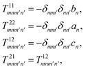 | (9) |
where
an,
bn, and
cn are the scattering coefficients defined as:
40,41| | 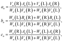 | (10) |
with
| | 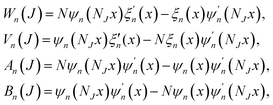 | (11) |
where
J is
L or
R and
x =
k1a;
ψn(
ρ) =
ρjn(
ρ),
ξn(
ρ) =
ρh(1)n(
ρ)with
jn(
ρ) being the spherical Bessel functions and
h(1)n(
ρ) being the spherical Hankel functions of the first kind; the relative refractive indices
NL,
NR and the mean refractive index
N take the expressions of

,

and
N = (
NL +
NR)/2, respectively.
Results and discussion
Based on the optical force obtained above, we can evaluate the optical force precisely and analyze its dependence on the particle chirality in this focused azimuthally polarized vortex beam. In what follows, we assume the input power P = 100 mW, free space wavelength λ0 = 1.064 μm, objective lens NA = 1.26, factor β0 = 1.5, refractive index n1 = 1.33 and relative permeability μ1 = 1 of the image space; the particle has a radius of a = 0.3 μm, relative permittivity ε2 = 2.5 and permeability μ2 = 1, and chirality parameter κ in the range between −1 to 1, with minus and plus signs separately denoting R (right-handed) and S (left-handed) enantiomers. Fig. 1 shows the transverse optical force distributions exerted on the S and R enantiomers with chirality parameters κ = 0.5 and −0.5 in the focal plane of the vector vortex beam with TC ![[small script l]](https://www.rsc.org/images/entities/i_char_e146.gif) = 5 and −5, where the arrows denote the direction and magnitude of the optical force, and the background represents the intensity distribution of the focused field. Notice that the azimuthal optical force exists uniformly on one circle where the radial optical force disappears, implying the enantiomers will be stably trapped in the radial direction and orbitally rotate around the optical axis. For the two enantiomers, both the direction and trajectory of their orbital motion are changed when the TC changes from
= 5 and −5, where the arrows denote the direction and magnitude of the optical force, and the background represents the intensity distribution of the focused field. Notice that the azimuthal optical force exists uniformly on one circle where the radial optical force disappears, implying the enantiomers will be stably trapped in the radial direction and orbitally rotate around the optical axis. For the two enantiomers, both the direction and trajectory of their orbital motion are changed when the TC changes from ![[small script l]](https://www.rsc.org/images/entities/i_char_e146.gif) = 5 to −5. For instance, the rotating direction changes from around the positive z-axis to around the negative z-axis, and the trajectory changes from being inside (outside) the intensity maxima to being outside (inside) the intensity maxima for the S and R enantiomers, as shown in Fig. 1(a) and (b) for S and Fig. 1(c) and (d) for R. As a result, the enantiomers can distinguish between beams carrying the vortex phase of opposite TCs, or the optical enantioseparation can be realized in this focused vector vortex beam.
= 5 to −5. For instance, the rotating direction changes from around the positive z-axis to around the negative z-axis, and the trajectory changes from being inside (outside) the intensity maxima to being outside (inside) the intensity maxima for the S and R enantiomers, as shown in Fig. 1(a) and (b) for S and Fig. 1(c) and (d) for R. As a result, the enantiomers can distinguish between beams carrying the vortex phase of opposite TCs, or the optical enantioseparation can be realized in this focused vector vortex beam.
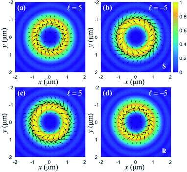 |
| | Fig. 1 Transverse optical force distributions experienced by the S (a and b) and R (c and d) enantiomers in the focal plane illuminated by the focused vector vortex beam with TC ![[small script l]](https://www.rsc.org/images/entities/i_char_e146.gif) = ±5. = ±5. | |
To further understand this special movement of the chiral particles, we carry out quantitative calculations in Fig. 2. We define a stable orbit r0 as corresponding to the loci where all radial optical forces on the chiral particle are balanced. The changes of the stable orbit r0 and azimuthal optical force Fϕ at the radial equilibrium position with the particle's chirality parameter κ are plotted in Fig. 2(a) and (b), respectively. With the increase of the chirality parameter κ, the stable orbit r0 is closer and closer to the focus for TC ![[small script l]](https://www.rsc.org/images/entities/i_char_e146.gif) = 5, whereas it is further and further away from the focus for TC
= 5, whereas it is further and further away from the focus for TC ![[small script l]](https://www.rsc.org/images/entities/i_char_e146.gif) = −5, implying that particles with different chiral parameters have different orbits which are affected by the handedness of the vortex beam. Regardless of whether TC
= −5, implying that particles with different chiral parameters have different orbits which are affected by the handedness of the vortex beam. Regardless of whether TC ![[small script l]](https://www.rsc.org/images/entities/i_char_e146.gif) = 5 or −5, the magnitude of the azimuthal optical force Fϕ increases with the increase of the chiral parameter |κ|, which is always larger than that of an achiral particle (κ = 0), demonstrating an enhanced orbital rotation on the chiral particles owing to the addition of chirality-related optical force. Moreover, for the incident beam with TC
= 5 or −5, the magnitude of the azimuthal optical force Fϕ increases with the increase of the chiral parameter |κ|, which is always larger than that of an achiral particle (κ = 0), demonstrating an enhanced orbital rotation on the chiral particles owing to the addition of chirality-related optical force. Moreover, for the incident beam with TC ![[small script l]](https://www.rsc.org/images/entities/i_char_e146.gif) = 5 acting on the R (S) enantiomer and the incident beam with TC
= 5 acting on the R (S) enantiomer and the incident beam with TC ![[small script l]](https://www.rsc.org/images/entities/i_char_e146.gif) = −5 acting on the corresponding S (R) enantiomer, the stable orbits r0 are the same; the azimuthal optical forces Fϕ are equal in magnitude while opposite in direction. Consequently, this focused vector vortex beam can trap particles with different chiral parameters on different orbits and induce enhanced orbital rotation on them, achieving an effective optical separation of chiral particles and simultaneous discrimination of the chirality of single particles.
= −5 acting on the corresponding S (R) enantiomer, the stable orbits r0 are the same; the azimuthal optical forces Fϕ are equal in magnitude while opposite in direction. Consequently, this focused vector vortex beam can trap particles with different chiral parameters on different orbits and induce enhanced orbital rotation on them, achieving an effective optical separation of chiral particles and simultaneous discrimination of the chirality of single particles.
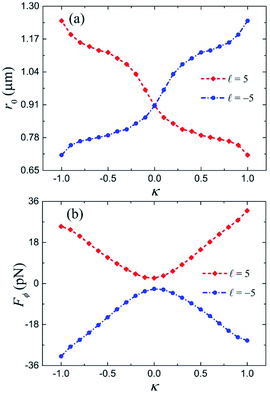 |
| | Fig. 2 The stable orbit r0 (a) and azimuthal optical force Fϕ (b) as functions of a particle's chirality parameter κ under the vector vortex beam illumination. | |
The normalized optical chirality density C ∝ Im[E·H*]42,43 distributions of the focused vector vortex beam in the focal plane are drawn in Fig. 3. Clearly, the optical chirality densities exhibit annular distributions and mainly concentrate on two rings inside and outside the circle of intensity maxima. At a fixed point, the orientation of the optical chirality density reverses when the sign of the TC is changed. In addition, the optical chirality density changes its sign along the radial direction, accompanied by the optical chirality “splitting” in the focal plane. It should be stressed here that the input beam (6) possesses neither optical chirality nor SAM at any point. Actual calculation finds that the total optical chirality is zero when the integral is performed in the whole focal plane, satisfying the conservation of optical chirality. Hence, the observed positive and negative optical chirality densities can be solely attributed to the formation of transverse electric and magnetic fields, with their relative phase ruled by the sign of the OAM. Combined with the previous analyses, the S and R enantiomers are trapped on the circle where the handedness of the enantiomers match the focused field.
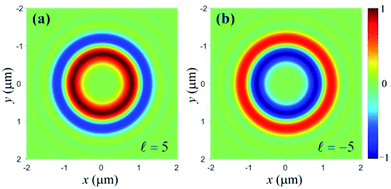 |
| | Fig. 3 Normalized optical chirality density distributions in the focal plane of focused vector vortex beam with TC ![[small script l]](https://www.rsc.org/images/entities/i_char_e146.gif) = 5 (a) and = 5 (a) and ![[small script l]](https://www.rsc.org/images/entities/i_char_e146.gif) = −5 (b). = −5 (b). | |
To present an intuitive picture of the optical separation and discrimination of the chiral particles, a sketch map is shown in Fig. 4. In such focused vector vortex beam, the S (R) enantiomer will be trapped on the inner (outer) side of the intensity maxima and orbital around the positive z-axis for TC ![[small script l]](https://www.rsc.org/images/entities/i_char_e146.gif) = 5, and trapped on the outer (inner) side of the intensity maxima and orbit around the negative z-axis for TC
= 5, and trapped on the outer (inner) side of the intensity maxima and orbit around the negative z-axis for TC ![[small script l]](https://www.rsc.org/images/entities/i_char_e146.gif) = −5. In addition, particles with different chirality parameters will be trapped on different orbits, as shown by the white circle (only a few are drawn). That is, the trapping of S and R enantiomers on the circle inside or outside of the intensity maxima depends on the sign of the OAM, while the specific circle depends on the magnitude of the particle's chirality parameter.
= −5. In addition, particles with different chirality parameters will be trapped on different orbits, as shown by the white circle (only a few are drawn). That is, the trapping of S and R enantiomers on the circle inside or outside of the intensity maxima depends on the sign of the OAM, while the specific circle depends on the magnitude of the particle's chirality parameter.
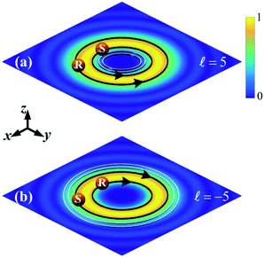 |
| | Fig. 4 A sketch map of the optical separation and discrimination of chiral particles using the focused vector vortex beam with TC ![[small script l]](https://www.rsc.org/images/entities/i_char_e146.gif) = 5 (a) and = 5 (a) and ![[small script l]](https://www.rsc.org/images/entities/i_char_e146.gif) = −5 (b). = −5 (b). | |
Next, we turn our attention to the dependences of the stable orbit r0 and azimuthal optical force Fϕ at the radial equilibrium position on the TC ![[small script l]](https://www.rsc.org/images/entities/i_char_e146.gif) of the vector vortex beam in Fig. 5, where the TC
of the vector vortex beam in Fig. 5, where the TC ![[small script l]](https://www.rsc.org/images/entities/i_char_e146.gif) takes values from −1 to −15 and 1 to 15. Since a sharp focal spot will be generated for TC
takes values from −1 to −15 and 1 to 15. Since a sharp focal spot will be generated for TC ![[small script l]](https://www.rsc.org/images/entities/i_char_e146.gif) = 1 and −1,44,45 the S (R) enantiomer under incident beam with TC
= 1 and −1,44,45 the S (R) enantiomer under incident beam with TC ![[small script l]](https://www.rsc.org/images/entities/i_char_e146.gif) = 1 (−1) illumination is stably trapped at the focus and experiences no rotation, as separately seen from Fig. 5(a) and (b). Besides, with increasing TC |
= 1 (−1) illumination is stably trapped at the focus and experiences no rotation, as separately seen from Fig. 5(a) and (b). Besides, with increasing TC |![[small script l]](https://www.rsc.org/images/entities/i_char_e146.gif) |, the stable orbit r0 increases in an approximately linear relation, and the azimuthal optical force |Fϕ| decreases with a slower and slower speed. This arises from the fact that the radius of annular focus increases, whereas the intensity is attenuated with the increasing value of TC |
|, the stable orbit r0 increases in an approximately linear relation, and the azimuthal optical force |Fϕ| decreases with a slower and slower speed. This arises from the fact that the radius of annular focus increases, whereas the intensity is attenuated with the increasing value of TC |![[small script l]](https://www.rsc.org/images/entities/i_char_e146.gif) |. Moreover, the stable orbit r0 of the S (R) enantiomer is smaller than that of the R (S) enantiomer under incident beam with TC
|. Moreover, the stable orbit r0 of the S (R) enantiomer is smaller than that of the R (S) enantiomer under incident beam with TC ![[small script l]](https://www.rsc.org/images/entities/i_char_e146.gif) > 0 (<0) illumination, while the situation of the azimuthal optical force |Fϕ| is just the opposite. This proves once again that the sign of the OAM determines the relative trapping position of the S and R enantiomers in the focal plane. In short, the magnitude of the OAM affects the rotating orbit and the magnitude of azimuthal optical force of the chiral particles, while the sign of the OAM affects the relative trapping position and the direction of orbital rotation of the enantiomers.
> 0 (<0) illumination, while the situation of the azimuthal optical force |Fϕ| is just the opposite. This proves once again that the sign of the OAM determines the relative trapping position of the S and R enantiomers in the focal plane. In short, the magnitude of the OAM affects the rotating orbit and the magnitude of azimuthal optical force of the chiral particles, while the sign of the OAM affects the relative trapping position and the direction of orbital rotation of the enantiomers.
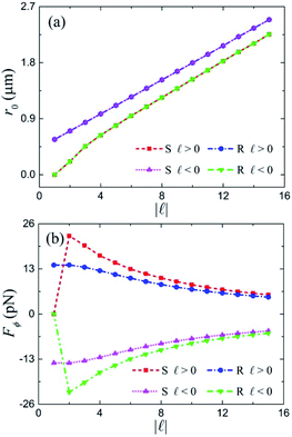 |
| | Fig. 5 Changes of the stable orbit r0 (a) and azimuthal optical force (b) with the TC ![[small script l]](https://www.rsc.org/images/entities/i_char_e146.gif) of the vector vortex beam. of the vector vortex beam. | |
Finally, the influences of particle size on the stable orbit r0 and azimuthal optical force Fϕ at the radial equilibrium position are investigated in Fig. 6, where particles with radii of 0.01 to 1 μm are considered. For radius a < 0.1 μm, because of the weak scattering, the particle will be trapped on a fixed circle as the stable orbit r0 remains constant, as shown in Fig. 6(a), and it undergoes no orbital rotation since the azimuthal optical force Fϕ is very small, as plotted in Fig. 6(b). When the radius increases from 0.1 to 1 μm, the stable orbit r0 undergoes a process of moving away first and then approaching and finally being fixed at the focus for the incident beam with TC ![[small script l]](https://www.rsc.org/images/entities/i_char_e146.gif) = 5 (−5) acting on the S (R) enantiomer, while it experiences a process of approaching first and then moving away and finally fixing at the focus for the incident beam with TC
= 5 (−5) acting on the S (R) enantiomer, while it experiences a process of approaching first and then moving away and finally fixing at the focus for the incident beam with TC ![[small script l]](https://www.rsc.org/images/entities/i_char_e146.gif) = 5 (−5) acting on the R (S) enantiomer. In addition, the magnitude of azimuthal optical force Fϕ gets bigger and bigger firstly, and then disappears where the particle is trapped at the focus for all four cases. Specifically, the maximum particle radius that can induce rotation for the incident beam with TC
= 5 (−5) acting on the R (S) enantiomer. In addition, the magnitude of azimuthal optical force Fϕ gets bigger and bigger firstly, and then disappears where the particle is trapped at the focus for all four cases. Specifically, the maximum particle radius that can induce rotation for the incident beam with TC ![[small script l]](https://www.rsc.org/images/entities/i_char_e146.gif) = 5 (−5) acting on the S (R) enantiomer is 0.66 μm, while it is 0.75 μm for the incident beam with TC
= 5 (−5) acting on the S (R) enantiomer is 0.66 μm, while it is 0.75 μm for the incident beam with TC ![[small script l]](https://www.rsc.org/images/entities/i_char_e146.gif) = 5 (−5) acting on the R (S) enantiomer. Therefore, the particle size affects the trapping position and rotation characteristics of the chiral particle, which plays an important role in the chiral separation and discrimination.
= 5 (−5) acting on the R (S) enantiomer. Therefore, the particle size affects the trapping position and rotation characteristics of the chiral particle, which plays an important role in the chiral separation and discrimination.
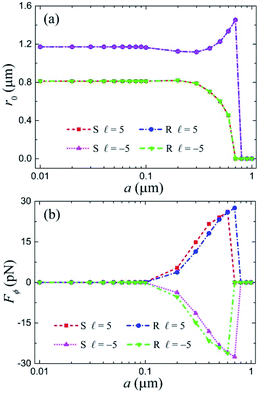 |
| | Fig. 6 Influence of particle size on the stable orbit r0 (a) and azimuthal optical force (b) under the focused vector vortex beam with TC ![[small script l]](https://www.rsc.org/images/entities/i_char_e146.gif) = ±5. = ±5. | |
In practice, the current scheme of optical separation and discrimination of chiral particles is not limited to the azimuthally polarized vortex beam. A tightly focused radially polarized or cylindrical vector vortex beam also carries local optical chirality that splits in the radial direction. Besides driving the orbital rotation, particles with opposite handedness would be separated in the radial direction. The only difference is that the azimuthal optical force they exert on the chiral particle is not as great as in the focused azimuthally polarized vortex beam.
Conclusions
In summary, we have numerically studied the role of OAM in chiral light–matter interactions. The tight focusing of an azimuthally polarized vortex beam carrying no SAM but only OAM results in the creation of radial-splitting optical chirality in the focal plane, and it can selectively trap S (R) enantiomers inside or outside the intensity maxima where the handedness of the enantiomer matches the focused field. The sign of the OAM of the input beam determines the sign of the optical chirality density of the focused field, as well as the relative trapping position of the enantiomers. The chiral particles with different chirality parameters will be trapped on different orbits and experience enhanced orbital motion, accomplishing an effective optical separation of chiral particles and simultaneous discrimination of the chirality of single particles. Furthermore, the magnitude of OAM and size of the particle affect both the trapping position and rotation characteristics of the chiral particles. Altogether, our study paves the way for potential applications of OAM, such as in optical enantioseparation, chiral detection, and sensing.
Conflicts of interest
There are no conflicts to declare.
Acknowledgements
This research is supported by the Natural Science Foundation of China (NSFC) under Grant Nos 11904395 and 11974417, and the Key Research Program of Frontier Sciences, CAS, Grant No. ZDBS-LY-JSC035.
References
-
A. Guijarro and M. Yus, The origin of chirality in the molecules of life: a revision from awareness to the current theories and perspectives of this unsolved problem, Royal Society of Chemistry, 2008 Search PubMed.
- Y. Wang, J. Xu, Y. Wang and H. Chen, Chem. Soc. Rev., 2013, 42, 2930–2962 RSC.
- L. A. Nguyen, H. He and C. Pham-Huy, Int. J. Biomed. Sci., 2006, 2, 85 CAS.
- S. K. Teo, W. A. Colburn, W. G. Tracewell, K. A. Kook, D. I. Stirling, M. S. Jaworsky, M. A. Scheffler, S. D. Thomas and O. L. Laskin, Clin. Pharmacokinet., 2004, 43, 311–327 CrossRef CAS PubMed.
- H. Caner, E. Groner, L. Levy and I. Agranat, Drug Discovery Today, 2004, 9, 105–110 CrossRef CAS PubMed.
- S. W. Smith, Toxicol. Sci., 2009, 110, 4–30 CrossRef CAS PubMed.
- B. S. Sekhon, J. Pestic. Sci., 2009, 34, 1–12 CrossRef CAS.
-
N. Berova, K. Nakanishi and R. W. Woody, Circular Dichroism: Principles and Applications, Wiley-VCH, New York, 2nd edn, 2000 Search PubMed.
- A. Canaguier-Durand, J. A. Hutchison, C. Genet and T. W. Ebbesen, New J. Phys., 2013, 15, 123037 CrossRef.
- G. Tkachenko and E. Brasselet, Nat. Commun., 2014, 5, 3577 CrossRef PubMed.
- E. Vinegrad, U. Hananel, G. Markovich and O. Cheshnovsky, ACS Nano, 2019, 13, 601–608 CrossRef CAS PubMed.
- M. Padgett, J. Courtial and L. Allen, Phys. Today, 2004, 57, 35–40 CrossRef CAS.
- D. L. Andrews, L. C. D. Romero and M. Babiker, Opt. Commun., 2004, 237, 133–139 CrossRef CAS.
- F. Araoka, T. Verbiest, K. Clays and A. Persoons, Phys. Rev. A, 2005, 71, 055401 CrossRef.
- W. Löffler, D. J. Broer and J. P. Woerdman, Phys. Rev. A, 2011, 83, 065801 CrossRef.
- K. A. Forbes and D. L. Andrews, Opt. Lett., 2018, 43, 435–438 CrossRef CAS PubMed.
- W. Brullot, M. K. Vanbel, T. Swusten and T. Verbiest, Sci. Adv., 2016, 2, e1501349 CrossRef PubMed.
- R. M. Kerber, J. M. Fitzgerald, S. S. Oh, D. E. Reiter and O. Hess, Commun. Phys, 2018, 1, 87 CrossRef.
- L. Ye, J. R. Rouxel, S. Asban, B. Rösner and S. Mukamel, J. Chem. Theory Comput., 2019, 15, 4180–4186 CrossRef CAS PubMed.
- P. Woźniak, I. De Leon, K. Höflich, G. Leuchs and P. Banzer, Optica, 2019, 6, 961–965 CrossRef.
- K. A. Forbes and D. L. Andrews, J. Phys.: Photonics, 2021, 3, 022007 CAS.
- X. Zhang and T. J. Cui, ACS Photonics, 2020, 7, 3291–3297 CrossRef CAS.
- S. Wang and C. Chan, Nat. Commun., 2014, 5, 3307 CrossRef CAS PubMed.
- M. H. Alizadeh and B. M. Reinhard, ACS Photonics, 2015, 2, 1780–1788 CrossRef CAS.
- Y. Zhao, A. A. Saleh and J. A. Dionne, ACS Photonics, 2016, 3, 304–309 CrossRef CAS.
- T. Zhang, M. R. C. Mahdy, Y. Liu, J. H. Teng, C. T. Lim, Z. Wang and C.-W. Qiu, ACS Nano, 2017, 11, 4292–4300 CrossRef CAS PubMed.
- M. Kamandi, M. Albooyeh, C. Guclu, M. Veysi, J. Zeng, K. Wickramasinghe and F. Capolino, Phys. Rev. Appl., 2017, 8, 064010 CrossRef.
- T. Cao and Y. Qiu, Nanoscale, 2018, 10, 566–574 RSC.
- W. Lu, H. Chen, S. Guo, S. Liu and Z. Lin, Opt. Lett., 2018, 43, 2086–2089 CrossRef CAS PubMed.
- M. Li, S. Yan, Y. Zhang, Y. Liang, P. Zhang and B. Yao, Phys. Rev. A, 2019, 99, 033825 CrossRef.
- R. Ali, F. A. Pinheiro, R. S. Dutra, F. S. S. Rosa and P. A. Maia Neto, Nanoscale, 2020, 12, 5031–5037 RSC.
- T. Zhu, Y. Shi, W. Ding, D. P. Tsai, T. Cao, A. Q. Liu, M. Nieto-Vesperinas, J. J. Sáenz, P. C. Wu and C.-W. Qiu, Phys. Rev. Lett., 2020, 125, 043901 CrossRef CAS PubMed.
- P. Waterman, Proc. IEEE, 1965, 53, 805–812 Search PubMed.
-
M. I. Mishchenko, L. D. Travis and A. A. Lacis, Scattering, absorption, and emission of light by small particles, Cambridge University, 2002 Search PubMed.
- B. Richards and E. Wolf, Proc. R. Soc. London, Ser. A, 1959, 253, 358 Search PubMed.
- K. S. Youngworth and T. G. Brown, Opt. Express, 2000, 7, 77–87 CrossRef CAS PubMed.
- Q. Zhan, Adv. Opt. Photonics, 2009, 1, 1–57 CrossRef CAS.
-
I. V. Lindell, A. Sihvola, S. Tretyakov and A. Viitanen, Electromagnetic Waves in Chiral and Bi-Isotropic Media, Artech House, Boston, 1994 Search PubMed.
- M. Yokota, S. He and T. Takenaka, J. Opt. Soc. Am. A, 2001, 18, 1681–1689 CrossRef CAS PubMed.
- F. Patti, R. Saija, P. Denti, G. Pellegrini, P. Biagioni, M. A. Iatì and O. M. Maragò, Sci. Rep., 2019, 9, 29 CrossRef PubMed.
-
C. F. Bohren and D. R. Huffman, Absorption and scattering of light by small particles, John Wiley & Sons, New York, 1983 Search PubMed.
- Y. Tang and A. E. Cohen, Phys. Rev. Lett., 2010, 104, 163901 CrossRef PubMed.
- M. Li, S. Yan, Y. Zhang and B. Yao, Nanoscale, 2020, 12, 15453–15459 RSC.
- S. Sato and Y. Kozawa, J. Opt. Soc. Am. A, 2009, 26, 142–146 CrossRef PubMed.
- M. Li, Y. Cai, S. Yan, Y. Liang, P. Zhang and B. Yao, Phys. Rev. A, 2018, 97, 053842 CrossRef CAS.
|
| This journal is © The Royal Society of Chemistry 2021 |
Click here to see how this site uses Cookies. View our privacy policy here.  Open Access Article
 a,
Shaohui
Yan
a,
Yanan
Zhang
a,
Xu
Chen
a and
Baoli
Yao
a,
Shaohui
Yan
a,
Yanan
Zhang
a,
Xu
Chen
a and
Baoli
Yao
 *ab
*ab
![[small script l]](https://www.rsc.org/images/entities/i_char_e146.gif) < 0 and to the left for
< 0 and to the left for ![[small script l]](https://www.rsc.org/images/entities/i_char_e146.gif) > 0.12 The question of how the OAM of the vortex beam might engage with chiral objects is a topic of resurgent interest.13–22 The initial studies concluded that the OAM plays no role in chiral light–matter interactions,13–15 while recent studies through OAM dichroism have shown that the OAM can produce chiroptical influence.17–21 Since weak interactions occur between molecules and the probing light, common OAM and SAM dichroism measurements are often challenging and cannot distinguish the chirality information of individual molecules. In recent years, optical forces on chiral objects have attracted considerable attention not only for the optical separation of enantiomers but also for the further identification of chirality.23–32 However, most of these studies have been restricted to the dipolar or geometric optics regime23–30 and use scalar beams with spatially uniform states of polarization (SOP) as illumination.23–29,31,32 Moreover, changing the SOP of the incident beam is usually needed to realize the recognition of another enantiomer.23–25,28,29
> 0.12 The question of how the OAM of the vortex beam might engage with chiral objects is a topic of resurgent interest.13–22 The initial studies concluded that the OAM plays no role in chiral light–matter interactions,13–15 while recent studies through OAM dichroism have shown that the OAM can produce chiroptical influence.17–21 Since weak interactions occur between molecules and the probing light, common OAM and SAM dichroism measurements are often challenging and cannot distinguish the chirality information of individual molecules. In recent years, optical forces on chiral objects have attracted considerable attention not only for the optical separation of enantiomers but also for the further identification of chirality.23–32 However, most of these studies have been restricted to the dipolar or geometric optics regime23–30 and use scalar beams with spatially uniform states of polarization (SOP) as illumination.23–29,31,32 Moreover, changing the SOP of the incident beam is usually needed to realize the recognition of another enantiomer.23–25,28,29
![[n with combining circumflex]](https://www.rsc.org/images/entities/b_char_006e_0302.gif) is the outwardly directed normal unit vector to the surface;
is the outwardly directed normal unit vector to the surface; ![[T with combining macron]](https://www.rsc.org/images/entities/b_char_0054_0304.gif) is the Maxwell stress tensor
is the Maxwell stress tensor


 ,
,  and N = (NL + NR)/2, respectively.
![[small script l]](https://www.rsc.org/images/entities/i_char_e146.gif) = 5 and −5, where the arrows denote the direction and magnitude of the optical force, and the background represents the intensity distribution of the focused field. Notice that the azimuthal optical force exists uniformly on one circle where the radial optical force disappears, implying the enantiomers will be stably trapped in the radial direction and orbitally rotate around the optical axis. For the two enantiomers, both the direction and trajectory of their orbital motion are changed when the TC changes from
= 5 and −5, where the arrows denote the direction and magnitude of the optical force, and the background represents the intensity distribution of the focused field. Notice that the azimuthal optical force exists uniformly on one circle where the radial optical force disappears, implying the enantiomers will be stably trapped in the radial direction and orbitally rotate around the optical axis. For the two enantiomers, both the direction and trajectory of their orbital motion are changed when the TC changes from ![[small script l]](https://www.rsc.org/images/entities/i_char_e146.gif) = 5 to −5. For instance, the rotating direction changes from around the positive z-axis to around the negative z-axis, and the trajectory changes from being inside (outside) the intensity maxima to being outside (inside) the intensity maxima for the S and R enantiomers, as shown in Fig. 1(a) and (b) for S and Fig. 1(c) and (d) for R. As a result, the enantiomers can distinguish between beams carrying the vortex phase of opposite TCs, or the optical enantioseparation can be realized in this focused vector vortex beam.
= 5 to −5. For instance, the rotating direction changes from around the positive z-axis to around the negative z-axis, and the trajectory changes from being inside (outside) the intensity maxima to being outside (inside) the intensity maxima for the S and R enantiomers, as shown in Fig. 1(a) and (b) for S and Fig. 1(c) and (d) for R. As a result, the enantiomers can distinguish between beams carrying the vortex phase of opposite TCs, or the optical enantioseparation can be realized in this focused vector vortex beam.

![[small script l]](https://www.rsc.org/images/entities/i_char_e146.gif) = ±5.
= ±5.![[small script l]](https://www.rsc.org/images/entities/i_char_e146.gif) = 5, whereas it is further and further away from the focus for TC
= 5, whereas it is further and further away from the focus for TC ![[small script l]](https://www.rsc.org/images/entities/i_char_e146.gif) = −5, implying that particles with different chiral parameters have different orbits which are affected by the handedness of the vortex beam. Regardless of whether TC
= −5, implying that particles with different chiral parameters have different orbits which are affected by the handedness of the vortex beam. Regardless of whether TC ![[small script l]](https://www.rsc.org/images/entities/i_char_e146.gif) = 5 or −5, the magnitude of the azimuthal optical force Fϕ increases with the increase of the chiral parameter |κ|, which is always larger than that of an achiral particle (κ = 0), demonstrating an enhanced orbital rotation on the chiral particles owing to the addition of chirality-related optical force. Moreover, for the incident beam with TC
= 5 or −5, the magnitude of the azimuthal optical force Fϕ increases with the increase of the chiral parameter |κ|, which is always larger than that of an achiral particle (κ = 0), demonstrating an enhanced orbital rotation on the chiral particles owing to the addition of chirality-related optical force. Moreover, for the incident beam with TC ![[small script l]](https://www.rsc.org/images/entities/i_char_e146.gif) = 5 acting on the R (S) enantiomer and the incident beam with TC
= 5 acting on the R (S) enantiomer and the incident beam with TC ![[small script l]](https://www.rsc.org/images/entities/i_char_e146.gif) = −5 acting on the corresponding S (R) enantiomer, the stable orbits r0 are the same; the azimuthal optical forces Fϕ are equal in magnitude while opposite in direction. Consequently, this focused vector vortex beam can trap particles with different chiral parameters on different orbits and induce enhanced orbital rotation on them, achieving an effective optical separation of chiral particles and simultaneous discrimination of the chirality of single particles.
= −5 acting on the corresponding S (R) enantiomer, the stable orbits r0 are the same; the azimuthal optical forces Fϕ are equal in magnitude while opposite in direction. Consequently, this focused vector vortex beam can trap particles with different chiral parameters on different orbits and induce enhanced orbital rotation on them, achieving an effective optical separation of chiral particles and simultaneous discrimination of the chirality of single particles.

![[small script l]](https://www.rsc.org/images/entities/i_char_e146.gif) = 5 (a) and
= 5 (a) and ![[small script l]](https://www.rsc.org/images/entities/i_char_e146.gif) = −5 (b).
= −5 (b).![[small script l]](https://www.rsc.org/images/entities/i_char_e146.gif) = 5, and trapped on the outer (inner) side of the intensity maxima and orbit around the negative z-axis for TC
= 5, and trapped on the outer (inner) side of the intensity maxima and orbit around the negative z-axis for TC ![[small script l]](https://www.rsc.org/images/entities/i_char_e146.gif) = −5. In addition, particles with different chirality parameters will be trapped on different orbits, as shown by the white circle (only a few are drawn). That is, the trapping of S and R enantiomers on the circle inside or outside of the intensity maxima depends on the sign of the OAM, while the specific circle depends on the magnitude of the particle's chirality parameter.
= −5. In addition, particles with different chirality parameters will be trapped on different orbits, as shown by the white circle (only a few are drawn). That is, the trapping of S and R enantiomers on the circle inside or outside of the intensity maxima depends on the sign of the OAM, while the specific circle depends on the magnitude of the particle's chirality parameter.
![[small script l]](https://www.rsc.org/images/entities/i_char_e146.gif) = 5 (a) and
= 5 (a) and ![[small script l]](https://www.rsc.org/images/entities/i_char_e146.gif) = −5 (b).
= −5 (b).![[small script l]](https://www.rsc.org/images/entities/i_char_e146.gif) of the vector vortex beam in Fig. 5, where the TC
of the vector vortex beam in Fig. 5, where the TC ![[small script l]](https://www.rsc.org/images/entities/i_char_e146.gif) takes values from −1 to −15 and 1 to 15. Since a sharp focal spot will be generated for TC
takes values from −1 to −15 and 1 to 15. Since a sharp focal spot will be generated for TC ![[small script l]](https://www.rsc.org/images/entities/i_char_e146.gif) = 1 and −1,44,45 the S (R) enantiomer under incident beam with TC
= 1 and −1,44,45 the S (R) enantiomer under incident beam with TC ![[small script l]](https://www.rsc.org/images/entities/i_char_e146.gif) = 1 (−1) illumination is stably trapped at the focus and experiences no rotation, as separately seen from Fig. 5(a) and (b). Besides, with increasing TC |
= 1 (−1) illumination is stably trapped at the focus and experiences no rotation, as separately seen from Fig. 5(a) and (b). Besides, with increasing TC |![[small script l]](https://www.rsc.org/images/entities/i_char_e146.gif) |, the stable orbit r0 increases in an approximately linear relation, and the azimuthal optical force |Fϕ| decreases with a slower and slower speed. This arises from the fact that the radius of annular focus increases, whereas the intensity is attenuated with the increasing value of TC |
|, the stable orbit r0 increases in an approximately linear relation, and the azimuthal optical force |Fϕ| decreases with a slower and slower speed. This arises from the fact that the radius of annular focus increases, whereas the intensity is attenuated with the increasing value of TC |![[small script l]](https://www.rsc.org/images/entities/i_char_e146.gif) |. Moreover, the stable orbit r0 of the S (R) enantiomer is smaller than that of the R (S) enantiomer under incident beam with TC
|. Moreover, the stable orbit r0 of the S (R) enantiomer is smaller than that of the R (S) enantiomer under incident beam with TC ![[small script l]](https://www.rsc.org/images/entities/i_char_e146.gif) > 0 (<0) illumination, while the situation of the azimuthal optical force |Fϕ| is just the opposite. This proves once again that the sign of the OAM determines the relative trapping position of the S and R enantiomers in the focal plane. In short, the magnitude of the OAM affects the rotating orbit and the magnitude of azimuthal optical force of the chiral particles, while the sign of the OAM affects the relative trapping position and the direction of orbital rotation of the enantiomers.
> 0 (<0) illumination, while the situation of the azimuthal optical force |Fϕ| is just the opposite. This proves once again that the sign of the OAM determines the relative trapping position of the S and R enantiomers in the focal plane. In short, the magnitude of the OAM affects the rotating orbit and the magnitude of azimuthal optical force of the chiral particles, while the sign of the OAM affects the relative trapping position and the direction of orbital rotation of the enantiomers.
![[small script l]](https://www.rsc.org/images/entities/i_char_e146.gif) of the vector vortex beam.
of the vector vortex beam.![[small script l]](https://www.rsc.org/images/entities/i_char_e146.gif) = 5 (−5) acting on the S (R) enantiomer, while it experiences a process of approaching first and then moving away and finally fixing at the focus for the incident beam with TC
= 5 (−5) acting on the S (R) enantiomer, while it experiences a process of approaching first and then moving away and finally fixing at the focus for the incident beam with TC ![[small script l]](https://www.rsc.org/images/entities/i_char_e146.gif) = 5 (−5) acting on the R (S) enantiomer. In addition, the magnitude of azimuthal optical force Fϕ gets bigger and bigger firstly, and then disappears where the particle is trapped at the focus for all four cases. Specifically, the maximum particle radius that can induce rotation for the incident beam with TC
= 5 (−5) acting on the R (S) enantiomer. In addition, the magnitude of azimuthal optical force Fϕ gets bigger and bigger firstly, and then disappears where the particle is trapped at the focus for all four cases. Specifically, the maximum particle radius that can induce rotation for the incident beam with TC ![[small script l]](https://www.rsc.org/images/entities/i_char_e146.gif) = 5 (−5) acting on the S (R) enantiomer is 0.66 μm, while it is 0.75 μm for the incident beam with TC
= 5 (−5) acting on the S (R) enantiomer is 0.66 μm, while it is 0.75 μm for the incident beam with TC ![[small script l]](https://www.rsc.org/images/entities/i_char_e146.gif) = 5 (−5) acting on the R (S) enantiomer. Therefore, the particle size affects the trapping position and rotation characteristics of the chiral particle, which plays an important role in the chiral separation and discrimination.
= 5 (−5) acting on the R (S) enantiomer. Therefore, the particle size affects the trapping position and rotation characteristics of the chiral particle, which plays an important role in the chiral separation and discrimination.
![[small script l]](https://www.rsc.org/images/entities/i_char_e146.gif) = ±5.
= ±5.