
 Open Access Article
 This Open Access Article is licensed under a Creative Commons Attribution-Non Commercial 3.0 Unported Licence
The effectiveness of Soxhlet extraction as a simple method for GO rinsing as a precursor of high-quality graphene†
Shimon Y. T.
Trolles-Cavalcante‡
a,
Asmita
Dutta‡
a,
Zdenek
Sofer
 b and
Arie
Borenstein
*a
b and
Arie
Borenstein
*a
aDepartment of Chemical Science, Ariel University, Ariel, Israel. E-mail: arieb@ariel.ac.il; Tel: +972 556802624
bDepartment of Inorganic Chemistry, University of Chemistry and Technology Prague, Technicka 5, 166 28 Prague 6, Czech Republic
First published on 13th July 2021
Abstract
Graphite-oxide (GO) is a valuable compound produced by the chemical oxidation of graphite. The procedure for converting graphite into GO includes two steps: oxidation and subsequent rinsing. Proper rinsing is essential to obtain processable and applicable graphite-oxide. Traditionally, the rinsing involves filtration or centrifugation; both processes are extremely time-consuming, expensive, unsafe, and produce environmentally hazardous liquid waste in large volume. This study reveals an alternative method to rinse graphite-oxide using a Soxhlet extractor. Since only the vapor of the solvent is used for washing, Soxhlet rinsing offers reuse of the same solvent for many automatic subsequent cycles, leading to considerable solvent savings, reducing pollutants and work time, and ensuring safer production. The quality of the produced GO is evaluated by Raman spectroscopy, X-Ray diffraction (XRD), inductively coupled plasma (ICP), elemental analysis, and electron microscopy. Moreover, we test the electrochemical performances of reduced GO (rGO), the main final product of graphite-oxide. Finally, we discuss the benefits involved in the suggested rinsing method and compare its profitability with traditional methods. Soxhlet rinsing is favored environmentally and economically. Particularly, the automatic operation of many washing sequences saves labor time, and the reuse of the washing solvent spares a large volume of chemically deleterious solvents.
1. Introduction
Graphene is a highly useful material, made solely of monolayered carbon atoms patterning a monoatomic honeycomb.1 Its sp2 structure results in outstanding physical and chemical properties including high electrical and thermal conductivities, high mechanical and chemical strength, and unique electronic and optical properties.2–5 Although carbon is extensively abundant and available, graphene's sophisticated and costly production impedes its wide use in various applications.6–10Graphene can be obtained through two major methods: first, polymerizing carbon molecules, such as benzene, known as the bottom-up approach, or by exfoliation of graphite stacked layers to graphene (top-down).11–13 The most widely used method of such exfoliation is known as Hummers' method, which involves oxidation of graphite powder in a strong acidic medium stimulating strong oxidation.14–16 Hummers himself used a waterless mixture of sulfuric acid, sodium nitrate and potassium permanganate17 followed by careful slow dilution in water and washing. Later, many improvements were suggested by different authors, while preserving the principal concept.18,19
The main drawbacks of Hummers' method are the loss and costly washing step. Since the graphene oxide slurry tends to clog regular filters, vacuum filtration becomes an inviable process. Instead, more expensive separation options are chosen such as tangential flow filtration or multi-step centrifugation that necessarily involve product loss and huge volumes of solvents. Specifically, centrifuging at accelerations exceeding 14![[thin space (1/6-em)]](https://www.rsc.org/images/entities/char_2009.gif) 700 m s−2 not only requires careful balancing and extra safety means to prevent hazardous accidents, but also requires expensive centrifuge equipment, and in many cases leads to centrifuge tubes breaking, and to product loss. Clearly, centrifugation suits only small quantities of GO.20
700 m s−2 not only requires careful balancing and extra safety means to prevent hazardous accidents, but also requires expensive centrifuge equipment, and in many cases leads to centrifuge tubes breaking, and to product loss. Clearly, centrifugation suits only small quantities of GO.20
In 1879, Franz von Soxhlet faced similar problems in his attempts to separate insoluble milk fats. He then invented the Soxhlet extractor.21 It allows efficient recycling of a small amount of solvent to dissolve a larger amount of material.
The similar requirements for simple, safer, and more effective washing of GO made us adapt the Soxhlet extractor for a scaled-up automatic graphene washing.22 In this paper, we examine and evaluate GO rinsing through Soxhlet extraction, its compatibility for GO and the final product. Two beneficial characteristics of Soxhlet rinsing offer considerable advantages: first, the automation of the process reduces dramatically the time lab technicians have to invest in processing the rinsing. After the Soxhlet setup is running no additional treatment is required. Second, the solvents used for the washing are reused for many subsequent washes. This cannot be done in regular filtration or centrifugation since the solvent gets contaminated. However, the vapor of this solvent is pure and may be reused for additional washing cycles.
2. Experimental
2.1 Materials
Graphite pellets, sulfuric acid, phosphoric acid, potassium permanganate, and hydrogen peroxide were purchased from Merck (NJ, USA).Graphene oxide was prepared using an improved Hummers' method. 1 g of the unprocessed graphite was put in a 1 L round flask with 500 mL concentrated sulfuric acid and a suitable magnetic stir bar, in an ice beaker. Then, 6 g of KMnO4 was added, while stirring vigorously and keeping the temperature below 15 °C. After 2 h the ice beaker was removed from under the balloon and replaced by warm water, and the heater of the magnetic stirrer was set to 45 °C. Then, 100 mL of deionized water was added dropwise for 1 h, while monitoring the temperature keeping it below 45 °C (Caution! This process is highly exothermic and is dangerous if done too fast). In the end the reaction was quenched with 28 dL of deionized water and 30 mL refrigerated 30% H2O2 solution. A black and yellow precipitate formed. The unwashed GO was centrifuged once to remove unreacted graphite. This single wash should be considered when calculating the elemental impurities. The centrifuged washed GO was centrifuged 15 times, according to the washing procedure described in ref. 15. The Soxhlet rinsing method is described in detail at the beginning of the Results and discussion section.
Raman spectroscopy was performed with an XploRA ONE™ MICRO-Raman system (Horiba Scientific, Japan) using a 532 nm laser source.
2.2 X-ray diffraction
The number of layers in the stack was calculated by dividing the crystalline size along the x-axis (Lc) or simply the crystal stack height, by the d-spacing of the (002) plane. Lc is calculated using the Scherrer equation:| Lc = (Kλ)/(β × cosѲ) | (1) |
Inductively Coupled Plasma (ICP) analysis was conducted using an LTI ICP-AES instrument from Laboratory Testing Inc. (Penn., USA). The samples were digested in nitric acid and hydrogen peroxide according to the EPA standard. Concentrations were given in ppm according to Con. = DF × C, where DF is the dilution factor and C is the data obtained from the ICP.
2.3 Laser reduction to rGO
A GO slurry was drop-cast onto stainless steel substrates. The slurry was dried on a hotplate for 10 h. The dry GO was then irradiated with a 40 W CO2 (10.6 mm) obtained using a Gravograph Laser engraver (LS100, France) at different powers and number of repetitions. A monolayer polyethylene membrane (16 mm, MTI Corp., USA) was used as a separator. The electrolyte solution was aqueous 1.0 M Na2SO4.STEM images were produced using an ultra-high resolution Tescan FE-SEM from Czech Republic. TEM samples were prepared by drop casting 5 mL diluted dispersions of 3D-ts-graphene powder in ethanol onto lacey-carbon supported TEM grids.
2.4 Conductivity measurements
The irradiated film was cut into 1 cm × 3 cm stripes and placed in contact with 1 mm stainless steel ribbons and was pressed between two glass plates. In the final assembly, the two ribbons were in contact for 1 cm2 of the graphene strip and between them there was a 1 cm2 clearance with only graphene. The loose ends of the stainless-steel ribbons were then connected to an ohmmeter with the help of two clips and wires. All of the non-graphene materials were measured also in a closed circuit with themselves showing a 0.3 ohm resistance. The graphene had 0.3 mm thickness, giving a cross-sectional area of 3 mm2.2.5 Electrochemical experiments
A Biologic VMP3 electrochemical potentiostat/galvanostat was employed for electrochemical characterization. A Ag/Ag+ reference electrode and a platinum wire counter electrode in a floated cell were used for the three-electrode setup. Two-electrode experiments were assembled in sealed coin cells. The counter electrode was mass balanced. Gravimetric capacitance was obtained by integration of the CV curves according to | (2) |
dE is the area of the CV curve in the operation potential window V, v is the scan rate in V s−1, m is the mass of the electrode active material, and (E1 − E0) is the potential scan window in volts. For the symmetric 2-electrode apparatus, the capacitance was doubled.
3. Results and discussion
3.1 Soxhlet extractor setup
Graphite-oxide was prepared by the improved Hummers' method as described in the Experimental section. After oxidation, the GO is extremely acidic and contaminated with ions and oxides of Na, Mn, K, S, and P, and thus requires thorough purification. Instead of the traditional time- and solvent-consuming filtration or centrifugation, this study employed a Soxhlet extractor to remove the undesired species from the GO. A scheme of the extractor setup can be seen in Fig. 1. A portion of the brown oxidized precipitant (pH < 1) was put inside a Soxhlet extractor equipped with a paper cup filter with the least amount of liquid possible. The extractor was filled halfway up.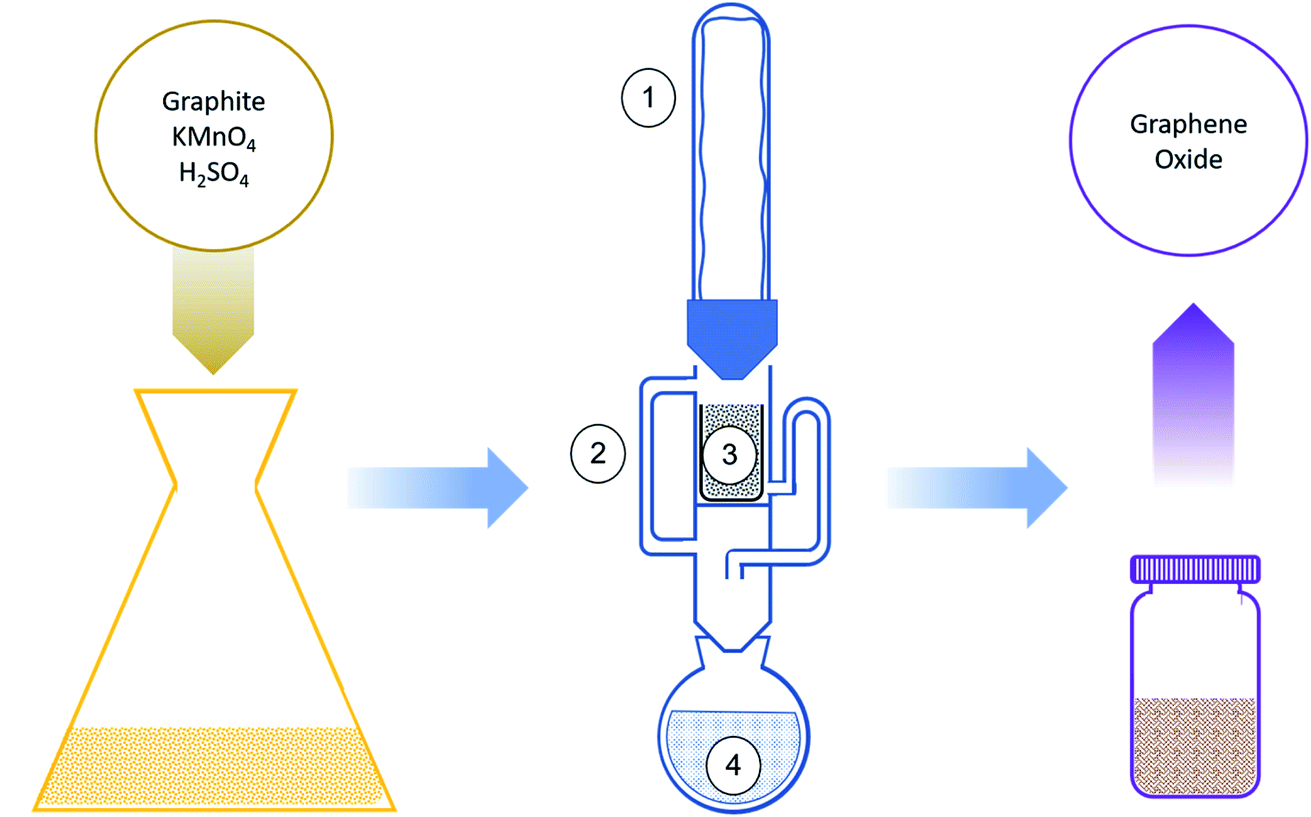 | ||
| Fig. 1 Oxidation process of graphite into graphene oxide. The graphite is oxidized by an improved Hummers' method. The contaminated oxidized graphite is washed in a Soxhlet extractor: (1) condenser, (2) Soxhlet extractor, (3) oxidized graphite in a cup, (4) boiling washing solvent. At the end of the process a neutral GO with no contamination is produced. | ||
A round-bottom flask was put on a heating mantle, and the Soxhlet extractor was connected on top of it, covered by a Liebig condenser. The condenser was cooled by a cold water loop. Deionized water or ethanol was added through the upper opening of the setup, directly wetting the slurry. The extractor flushes and additional washing water were added to refill it halfway again. The sum of washing solvent added was 250 mL for 10 g of graphite batch.
The rate of the Soxhlet washing is mainly affected by the steam flow. For proper cleaning of the product the main goal is a certain number of flushing cycles, which is directly related to the solvent's precipitation rate. Because the condenser's surface area was big enough and cooling water was kept at a low enough temperature, to have as close to no steam loss as possible, the precipitation rate was the same as the steam flow. The steam flow was measured by, after thermal stabilization of the apparatus, removal of the condenser from the top of the apparatus and addition of an angled tube section between the apparatus and the condenser, making the condenser move more than 1.7 rad from its original position, redirecting the condensed flow out of the equipment, and collecting the condensed solvent for 60 s. Furthermore, as described in the Introduction section, the pureness of the condensed solvent is of great importance, since the main advantage of the Soxhlet is the reuse of the washing solvent. It is enabled because, although the solvent gets contaminated after washing the GO sample, and cannot be reused for washing, its vapor is not contaminated and can continue washing for many more cycles. To validate this assumption, the condensate was analyzed by Inductively Coupled Plasma (ICP) spectroscopy to ensure vapor purity. An optimization study sets the best performances achieved at a steam flow close to 600 mg s−1. Lower flow rates increase rinsing time and rates may cause overflowing sample loss. Of course, larger steam flows are probable in wider flushing tubes. During rinsing, the rinsed impurities will be collected in the round bottom flask together with ethanol, which will later boil up again. When it boils, it might catch some impurities, and these will impurify the slurry again. The ICP tests on the condensed ethanol found that the concentrations were below the minimal detectable concentration of the relevant solvent impurities (<0.001 ppm, detection limit of the ICP). Importantly, the solvent can work longer before substitution or any other treatment needed. This promises continuous mechanized rinsing without the need for human intervention.
3.2 Sample characterization
The slurry obtained after Soxhlet rinsing was a black paste. A SEM image of the dried slurry shows typical GO sediments. General curved lines of the GO sheets can be seen and a layered macro-structure can be seen (Fig. S1, ESI†).To characterize the washed mixture as graphite-oxide, the samples were characterized by Raman spectroscopy.23Fig. 2a compares the Raman spectra of the graphite used as a precursor and the graphite-oxide washed using a Soxhlet extractor. Typically, carbon materials consist of two major peaks. First, the Raman shift at ∼1350 cm−1 (the so-called D-band) corresponds to disordered carbon, defects, and sp3 carbon, while the second peak at ∼1600 cm−1 (the G-band) is attributed to graphitic carbons (sp2). As expected, the Raman spectra of the untreated graphite show two major peaks. There is a sharp G-band at 1590 cm−1 (the G-band), attributed to graphitic carbons (sp2), proving a high degree of graphitization. There is a second, minor, peak at 1370 cm−1 (the so-called D-band) that corresponds to disordered carbon. The Raman spectra of the graphite-oxide, however, dramatically change. The D and G bands (1390 and 1610 cm−1, respectively) are both very broad. Moreover, the degree of graphitization of carbon compounds is usually evaluated by ID/IG, the ratio between the intensities of the D-band to that of the G-band.24 Soxhlet-washed graphite oxide shows a typical ID/IG value of 1.05, much higher than that of graphite (0.61). For comparison, the ID/IG ratio of a GO washed through the traditional method (centrifugation) shows similar Raman spectra, proving that GO washed with a Soxhlet extractor demonstrates a typical pattern (ID/IG = 0.68; Fig. S2 in the ESI†).
 | ||
| Fig. 2 Sample characterization. (a) Raman spectra and (b) X-ray diffraction spectra of graphite-oxide, oxidized by an improved Hummers' method and washed by Soxhlet extraction and by a traditional method. | ||
X-Ray Diffraction (XRD) is another indicative method to evaluate the oxidation process of graphite into GO.25 The XRD spectra of pristine graphite and the Soxhlet-rinsed GO are presented in Fig. 2b. The spectra of the graphite consist of a sharp peak at 2θ = 26.4° attributed to the (002) plane and represent an interlayer d-spacing of 0.36 nm, typical for graphite. After oxidation and washing with Soxhlet, the graphite-oxide shows a different XRD pattern. The peak at 26.4° shifts to a lower angle due to the interlayer distance increase. A characteristic (001) peak is observed at 2θ = 10.3°, corresponding to a d-spacing of 0.85 nm. The spacing between graphite layers arises from oxygen functionalities intercalated in-between the layers, representing a high degree of oxidation. In addition, a second peak is observed at 2θ = 42.3°, for the in-plane (100) pattern. For comparison, the XRD spectra of the GO washed in a traditional way include peaks in similar locations (Fig. S3 in the ESI†). One can calculate the number of sheets in a single graphitic particle by XRD according to N = Lc/d, where N is the number of layers in a single particle, Lc is the crystal stack height (using the Scherrer equation, see the Experimental section), and d is the space between layers. The Lc of the GO reduces to 65 nm and N = 76 layers.
The change in chemical composition during oxidation reaction was determined by elemental analysis and by inductively coupled plasma (ICP) comparing the graphite precursor and the graphite-oxide. The results of the elemental analysis are summarized in Table 1. As expected, graphite consists almost entirely of carbon (97.52%) with small residues of oxygen (1.73%), sulfur (0.67%) and hydrogen (0.02%) and other impurities (0.41%). After oxidation with Hummers' method, the graphite-oxide samples show a much higher quantity of oxygen and the O/C ratio changed from 0.018 in graphite to 2.152.
| C | H | O | N | S | O/C ratio | |
|---|---|---|---|---|---|---|
| Graphite | 96.52 | 0.02 | 3.73 | 0 | 0.67 | 0.038 |
| GO-Soxhlet | 30.54 | 2.62 | 65.73 | 0.06 | 0.03 | 2.152 |
| GO-traditional | 31.40 | 2.49 | 63.92 | 0.33 | 1.58 | 2.035 |
Inductively coupled plasma (ICP) is a trace-analysis method with a detection limit as low as 0.001 ppm. These measurements are very important to the current study, focusing on a simpler and more effective washing process. The Soxhlet washed GO contains smaller amounts of impurities, similar and even less than traditionally washed GO, and far less than the unwashed GO (as prepared by Hummers' methods without washing, Table S1†). The results of the ICP measurements of the graphite precursor, the Soxhlet washed GO and (centrifuged) washed GO, collected from three different batches, are presented in Table 2, ordered alphabetically and illustrated in Fig. 3a. The graphite precursor contains large amounts of iron (1419 ppm), maybe as a result of its origin in steel electric arc furnaces. However, the iron is effectively washed and is present in much smaller concentrations in all other samples. The second most dominant element present in the graphite is potassium (325 ppm). The potassium level increases dramatically in the graphite-oxide samples, obviously due to the potassium permanganate added during Hummers' oxidation process. The K level reaches 3174 ppm in the unwashed GO (Table S1 in the ESI;† see also the Experimental section). After rinsing the GO in Soxhlet the potassium level decreases to 548 ppm. This is more than three times better than the traditional centrifugation washing, ending up with 1683 ppm. Similar results are obtained in the sodium level, where Soxhlet washing reduces the Na content to half in comparison to centrifugation (423 and 875 ppm, respectively). Two other significant elements detected in ICP measurement are magnesium and manganese. Mg and Mn are present in both centrifuged and Soxhlet washed GO slurries but absent in the original graphite. Mn impurities are leftovers of the oxidizing agent, KMnO4. The samples washed with Soxhlet contain only half of the amount found in the traditionally washed GO (669 and 1313 ppm, respectively). Overall, the ICP measurements indicate that Soxhlet rinsing reduces complexity, saves time, risks, and costs with no purification forfeiture. The unusual amount of Mg detected in GO-Soxhlet originates from the filter paper used to hold the GO during washing. Apparently, the paper was not clean enough. This was proved by ICP measurement of the paper soaked in DI water revealing traces of Mg. For comparison, ICP with only DI water containing no detectable Mg is shown in Table S5.†
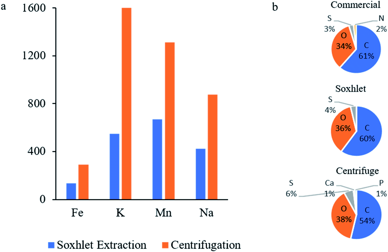 | ||
| Fig. 3 (a) Elemental impurities detected in GO washed with Soxhlet as described in this study and centrifugation according to the procedure described in ref. 15. (b) Elemental analysis by XPS. | ||
To further compare the effectiveness of the proposed method, we characterized the impurity level of a commercially available graphite-oxide, purchased from a well-known American company. The washing method of this product is not specified. The results of the ICP measurements are presented in Table S1.† The levels of all monitored elements are considerably higher in the commercial GO compared to the GO washed with Soxhlet. The only element present in lower concentration is Mg, which strongly depends on the origin and processing of the graphite and GO.
The elemental composition of the product can be reconfirmed by XPS. Although XPS is a surface analysis method, the exact elemental measurement for a bulk material might be less accurate. Elemental composition of the Soxhlet washed, the traditional washed and the commercial GO is plotted in Fig. 3b and tabled in Table S4.† In all samples the carbon and oxygen contents are similar. The sulphur content was relatively large, as a result of the sulfuric acid used in Hummers' method. Yet, Soxhlet washed GO contained less sulfur than the centrifuged GO (3.63 to 5.93%). The commercial GO contains 1.69% of N, which was not detected in the GO prepared in our lab. As we do not know the production process of the commercial GO we cannot explain the source of this nitrogen impurity. The full XPS survey and C 1s scans are also included in Fig. S4 and S5,† respectively.
The yield of the process was 61.5%. Most of the mass loss comes from the product trapped in the filter paper. We believe this is only a technical issue, and yield could be dramatically improved with adjusting the Soxhlet setup.
3.3 Reduced GO
Graphite-oxide is mainly used as a precursor for graphene upon reduction. Oxidation of graphite into graphite-oxide followed by re-reduction and exfoliation does not restore the original graphite structure. Instead, separated sheets of the sp2 carbon allotrope are formed, known as graphene. To obtain a high-grade reduced graphene-oxide (rGO), the GO precursor must be highly purified. Hence, evaluation of the graphene produced out of the GO is another way to verify the effectiveness and applicability of the Soxhlet washing method.26 Soxhlet-washed GO was reduced by CO2 laser irradiation, according to a method recently developed and described elsewhere.27,28 The laser reduction offers a simple, eco-friendly, and tunable method to obtain high-grade 3D graphene29,30 (Fig. 4a). The chemical composition of the product was determined by elemental analysis. As expected, the oxygen content is reduced by laser irradiation to 50.22% (Table S2†), leaving the O/C ratio closer to that of the original graphite (0.22). The impurities present in the rGO, obtained by ICP are comparable with those obtained for the GO, but somewhat higher, since the mass of the material left after carbonization (carbon and oxygen) is reduced, which increases the relative concentration of the heavier elements (Table S3†). A scanning electron microscope (SEM) image of the rGO reveals the layered structure of the rGO particle (Fig. 4a, layers are marked in Fig. S6†). The size of the particles is approximately 1 micrometer in diameter, in accordance with the size calculated for the graphite precursor by XRD. An image of a separated rGO sheet through transmission electron microscopy (TEM) is presented in Fig. 4b. The effect of the laser reduction is visualized by the bare eye, as the compound changes color from dark brown to black (Fig. 4c). The sheet is almost transparent to the electron beam, proving that only a few sheets are stacked in the turbostratic graphene. The number of layers can be determined by a topographical AFM scan. A width of 3 nm corresponds to 10 stacked layers (Fig. 4d and e). | ||
| Fig. 4 Physical and chemical characterization of laser reduced GO. (a) SEM image. Magnification: 200 k. (b) TEM image of an isolated rGO sheet. (c) Visible photograph demonstrating the color change between GO (left) and rGO (rGO). (d) AFM topographical scan of an isolated turbostratic rGO. (e) A height profile of the AFM presented in (d). (f) Raman spectra of GO and laser reduced GO. (g) XRD pattern of GO and laser reduced GO. | ||
Raman spectroscopy of the rGO rinsed by Soxhlet introduces a typical graphene-like spectrum, with an intense and sharp G-band at 1585 cm−1 and a minor D-band peak at 1370 cm−1 (Fig. 4f). The spectra of the rGO demonstrate high similarity to the graphite precursor, with the most notable difference being the shoulder at 2670 cm−1 present only in graphite's spectra. Importantly, the outstanding ID/IG ratio of 0.67 indicates a high graphitic level. This proves the impressive effectiveness of the production process. In fact, the high quality rGO obtained with the Soxhlet method suggests a promising approach for a cost-effective, eco-friendly, and safe process for up-scaling production of graphene. XRD measurement of the produced rGO further confirms the graphene-like structure of the reduced GO (Fig. 4g).
Electrical conductivity is an important property of rGO. Many applications including energy systems, sensors, and electronics require high conductivity. For us, electrical conductivity is an important way to evaluate the success of the Soxhlet in purifying the oxidized GO, since heteroatom impurities may suppress its performances. The samples were submitted to an electrical conductivity test. While the GO was found to show practically insulating behavior (1.3 × 10⁻⁷ S m−1), the rGO demonstrated a high conductivity of 24 S m−1.
3.4 Electrochemical characterization
Electrochemical experiments are highly indicative in sensitively identifying the presence of impurities since they immediately stimulate parasitic redox currents. After exfoliation in an ultrasonic bath, the reduced graphene oxide (rGO) was inserted as a self-standing electrode into an aqueous electrochemical cell and cyclic voltammetry (CV), galvanostatic charge–discharge (GCD) and electrochemical impedance spectroscopy (EIS) measurements were applied to evaluate its performances.rGO was loaded on a stainless steel current collector and placed into a 3-electrode floated 1 M Na2SO4 aqueous electrolyte cell, equipped with a Ag/AgCl reference electrode. The open circuit voltage (OCV) of the electrode is 0.310 V (0.08 vs. SHE). Cyclic voltammetry of the rGO reduced from the Soxhlet-rinsed GO is presented in Fig. 5a. A capacitive response is seen along most of the electrical window between 1.0 and −1.0 V. A small non-EDLC shape is observed at the negative domain, probably an irreversible reduction of the electrode. This shoulder suggests incomplete reduction by the laser, as confirmed by elemental analysis. The average capacitance at both positive and negative domains is 265 F g−1. This high capacitance proves the high quality of the rGO. The capacitance was found to be stable for at least the first 1000 cycles. This stability proves the absence of impurities that could contaminate the electrode and leach or oxidize during cycling.
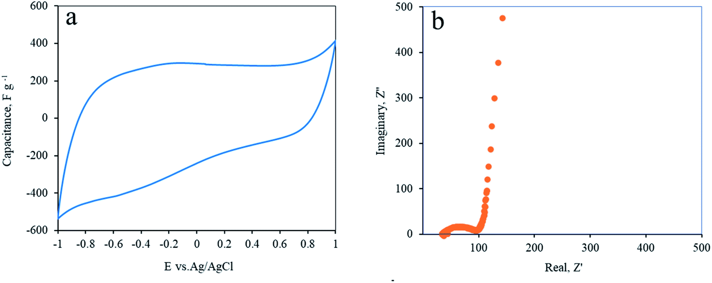 | ||
| Fig. 5 Electrochemical performances of the rGO electrode in an aqueous electrolyte. (a) Cyclic voltammetry of Soxhlet-rinsed rGO at a scan rate of 20 mV s−1. (b) Nyquist plot illustration of electrochemical impedance spectroscopy of the rGO electrode at OCV. | ||
Electrochemical impedance spectra (EIS) of rGO electrodes are presented in Fig. 5b. A typical semicircle shape at the high frequency domain was followed by an almost vertical line at the lower frequencies. This proves the highly capacitive behavior of the electrodes with low internal resistivity.31 The turning point is at 2.1 Hz.
The effectiveness of the washing can also be demonstrated by the electrocatalytic performances of the rGO. In this regard, impurities such as transition-metal oxides that are left in the GO, and consequently in the rGO, can catalyze electrochemical reactions such as the oxygen evolution reaction (OER) or oxygen reduction reaction (ORR). Of course, we do not mean to claim that unwashed carbons have any advantage over properly washed materials. Obviously, the catalytic “improvement” of contaminated rGO compared to clean RGO is only temporary, since the heteroatoms are not bonded to the carbon and will sooner or later surely dissolve into the solution. However, comparing the reduction potential of washed and unwashed materials can visualize the presence of impurities in the electrode. MnO2 is well known for its catalytic properties for the OER and ORR.32–34 Since Mn was detected in ICP measurements in relatively large quantities at the unwashed GO, it could be a fair indicator for impurity removal by Soxhlet extraction. Fig. 6 shows the linear sweep voltammetry (LSV) of the as-prepared (without washing) and Soxhlet-washed rGO electrodes. Conspicuously, the unwashed electrodes demonstrate smaller negative overpotential compared to the Soxhlet-washed rGO electrode. The 0.086 V higher onset potential of the Soxhlet-washed rGO reconfirms the effectiveness of the purification method.
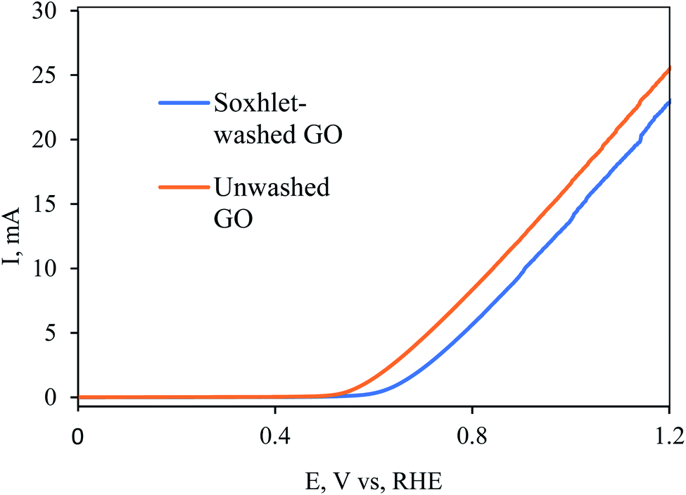 | ||
| Fig. 6 Oxygen evolution reaction (OER) on Soxhlet-washed and unwashed (as-oxidized) rGO electrodes. | ||
3.5. Discussion
After we demonstrated the chemical feasibility of Soxhlet rinsing of graphite-oxide after Hummers' oxidation method, we must evaluate the profitability of the suggested process. Several aspects must be considered: the energetic cost, work time, solvent costs, and environmental footprints, which also translated to economical profitability. The suggested rinsing process is favorable mainly in the required volume of washing solvents and spares the need for repeating centrifugation, replacing the washing solvents and other time-consuming actions.In terms of solvents savings, the main advantage is the ability to use the same solvent repeatedly, instead of replacing the solvent in every washing step. This can cut the costs by 7–10 fold.
Table 3 summarizes the required resources to wash 1 kg of graphite-oxide in different methods. The estimated values presented for centrifugation and filtration refer to specific procedures described in ref. 6 and 12, although similar standards exist in other publications as well. The values stated for the Soxhlet method are calculated according to the equipment infrastructures available in our lab. Obviously, industrial-level apparatus changes the numbers dramatically. The results are illustrated in Fig. S7.†
| Process/Item | Soxhlet extractiona | Centrifugationb | Filtrationc |
|---|---|---|---|
| a Values are calculated for the synthesis procedure reported in this study. b Values are estimated according to the experimental description in ref. 15. c Values are estimated according to the experimental description in ref. 11. | |||
| Graphite (kg) | 1 | ||
| Water rinsing (liters) | 250 | 1080 | 1000 |
| Electricity (kWh) | 110 | 18140 |
2200 |
| Rinsing time (hours) | 120 | 30240 |
240 |
| Net labor time (hours) | 2 | 70 | 10 |
As shown in Table 3, the Soxhlet extraction method introduces net benefits in terms of water consumption (30 times less than filtration and 10000 times less than centrifugation) and electricity consumption (20 and 165 times, respectively). Importantly, it is considerably more efficient with respect to the processing time. The GO batch exceeds the required time for the washing process. This is a notable improvement for both lab and industrial production. Finally, it has been shown that Soxhlet rinsing is profoundly preferred in terms of labor time, i.e. the practical time a trained lab technician invests in order to complete the washing task, excluding waiting while instruments are running. Personally, in our lab, starting Soxhlet washing significantly shortened and simplified GO preparation. Clearly, all these aspects have a significant effect on the economical profitability of the production. These advantages encourage commercial production of GO with Soxhlet extraction rinsing.
4. Conclusions
Graphite-oxide, prepared by an improved Hummers' method, was rinsed by Soxhlet extraction. The automatic extraction method offers significant benefits in terms of manpower working time, safety, consumables and washing solvents saving and environment friendliness. Profound characterization of graphite-oxide washed by Soxhlet shows successful and effective rinsing. The chemical structure and composition of the product were evaluated by elemental analysis, Raman, and XRD. All measurements proved positive formation of graphite-oxide. Moreover, the presence of impurities was monitored by ICP. Impurities of K, Mn, and S were found to reduce relative to both the graphite precursor and compared to the traditional rinsing method. Finally, the GO was reduced into rGO by laser irradiation. The reduced GO reconfirms the effectiveness of the Soxhlet rinsing method, showing high electrochemical performances.Conflicts of interest
The authors declare no conflicts of interest.Acknowledgements
The authors would like to acknowledge The Ministry of Energy for their support.References
- K. S. Novoselov, A. K. Geim, S. V. Morozov, D. Jiang, Y. Zhang, S. V. Dubonos, I. V. Grigorieva and A. A. Firsov, Science, 2004, 306(5696), 666–669 CrossRef CAS PubMed
.
- A. A. Balandin, S. Ghosh, W. Bao, I. Calizo, D. Teweldebrhan, F. Miao and C. N. Lau, Nano Lett., 2008, 8, 902–907 CrossRef CAS PubMed
- A. K. Geim and A. H. MacDonald, Phys. Today, 2007, 60, 35–41 CAS
- A. N. Grigorenko, M. Polini and K. S. Novoselov, Nat. Photonics, 2012, 6, 749–758 CrossRef CAS
- D. G. Papageorgiou, I. A. Kinloch and R. J. Young, Prog. Mater. Sci., 2017, 90, 75–127 CrossRef CAS
- V. Urbanová, P. Lazar, N. Antonatos, Z. Sofer, M. Otyepka and M. Pumera, ACS Appl. Mater. Interfaces, 2020, 12(18), 20383–20392 CrossRef PubMed
- Q.-L. Zhu and Q. Xu, Chem. Soc. Rev., 2014, 43, 5468–5512 RSC
- J. E. Kim, T. H. Han, S. H. Lee, J. Y. Kim, C. W. Ahn, J. M. Yun and S. O. Kim, Angew. Chem., Int. Ed., 2011, 50, 3043–3047 CrossRef CAS PubMed
- H. J. Jung, S. Padmajan Sasikala, K. E. Lee, H. S. Hwang, T. Yun, I. H. Kim, S. H. Koo, R. Jain, G. S. Lee, Y. H. Kang, J. G. Kim, J. T. Kim and S. O. Kim, ACS Cent. Sci., 2020, 6, 1105–1114 CrossRef CAS PubMed
- I. H. Kim, T. H. Im, H. E. Lee, J. S. Jang, H. S. Wang, G. Y. Lee, I. D. Kim, K. J. Lee and S. O. Kim, Small, 2019, 15, 1–8 Search PubMed
- R. V. Salvatierra, V. H. R. Souza, C. F. Matos, M. M. Oliveira and A. J. G. Zarbin, Carbon, 2015, 93, 924–932 CrossRef CAS
- L. Tang, X. Li, R. Ji, K. S. Teng, G. Tai, J. Ye, C. Wei and S. P. Lau, J. Mater. Chem., 2012, 22, 5676–5683 RSC
- C. Moreno, M. Vilas-Varela, B. Kretz, A. Garcia-Lekue, M. V. Costache, M. Paradinas, M. Panighel, G. Ceballos, S. O. Valenzuela, D. Peña and A. Mugarza, arXiv, 2018, 203, 23–28 Search PubMed
- M. D. P. Lavin-Lopez, A. Romero, J. Garrido, L. Sanchez-Silva and J. L. Valverde, Ind. Eng. Chem. Res., 2016, 55, 12836–12847 CrossRef CAS
- R. S. Edwards and K. S. Coleman, Nanoscale, 2013, 5, 38–51 RSC
- J. Chen, B. Yao, C. Li and G. Shi, Carbon, 2013, 64, 225–229 CrossRef CAS
- W. S. Hummers and R. E. Offeman, J. Am. Chem. Soc., 1958, 80, 1339 CrossRef CAS
- H. Yu, B. Zhang, C. Bulin, R. Li and R. Xing, Sci. Rep., 2016, 6, 1–7 CrossRef CAS PubMed
- J. H. Kang, T. Kim, J. Choi, J. Park, Y. S. Kim, M. S. Chang, H. Jung, K. T. Park, S. J. Yang and C. R. Park, Chem. Mater., 2016, 28, 756–764 CrossRef CAS
- T. Z. Shen, S. H. Hong and J. K. Song, Carbon, 2014, 80, 560–564 CrossRef CAS
- M. D. Luque de Castro and L. E. García-Ayuso, Anal. Chim. Acta, 1998, 369, 1–10 CrossRef CAS
- M. D. Luque de Castro and F. Priego-Capote, J. Chromatogr. A, 2010, 1217, 2383–2389 CrossRef CAS PubMed
- A. Cuesta, P. Dhamelincourt, J. Laureyns, A. Martínez-Alonso and J. M. D. Tascón, Carbon, 1994, 32, 1523–1532 CrossRef CAS
- L. G. Caņado, K. Takai, T. Enoki, M. Endo, Y. A. Kim, H. Mizusaki, A. Jorio, L. N. Coelho, R. Magalhães-Paniago and M. A. Pimenta, Appl. Phys. Lett., 2006, 88, 1–4 Search PubMed
- L. Stobinski, B. Lesiak, A. Malolepszy, M. Mazurkiewicz, B. Mierzwa, J. Zemek, P. Jiricek and I. Bieloshapka, J. Electron Spectrosc. Relat. Phenom., 2014, 195, 145–154 CrossRef CAS
- A. Borenstein, R. Attias, O. Hanna, S. Luski, R. B. Kaner and D. Aurbach, ChemElectroChem, 2017, 4, 2660–2668 CrossRef CAS
- A. Borenstein, V. Strauss, M. D. Kowal, M. Anderson and R. B. Kaner, Small, 2019, 1904918 CrossRef CAS PubMed
- A. Borenstein, V. Strauss, M. D. Kowal, M. Yoonessi, M. Muni, M. Anderson and R. B. Kaner, J. Mater. Chem. A, 2018, 20463–20472 RSC
- R. Ye, D. K. James and J. M. Tour, Acc. Chem. Res., 2018, 51, 1609–1620 CrossRef CAS PubMed
- V. Strauss, M. Muni, A. Borenstein, B. Badamdorj, T. Heil, M. D. Kowal and R. Kaner, Nanoscale, 2019, 11, 12712–12719 RSC
- A. Bonanni and M. Pumera, Electrochem. Commun., 2013, 26, 52–54 CrossRef CAS
- K. A. Stoerzinger, M. Risch, B. Han and Y. Shao-Horn, ACS Catal., 2015, 5, 6021–6031 CrossRef CAS
- F. Cheng, Y. Su, J. Liang, Z. Tao and J. Chen, Chem. Mater., 2010, 22, 898–905 CrossRef CAS
- L. Ma, N. Meng, Y. Zhang and F. Lian, Nano Energy, 2019, 58, 508–516 CrossRef CAS
Footnotes |
| † Electronic supplementary information (ESI) available. See DOI: 10.1039/d1na00382h |
| ‡ These authors contributed equally. |
| This journal is © The Royal Society of Chemistry 2021 |