
 Open Access Article
 This Open Access Article is licensed under a Creative Commons Attribution-Non Commercial 3.0 Unported Licence
Interplay between inter- and intraparticle interactions in bi-magnetic core/shell nanoparticles†
A.
Omelyanchik
 ab,
S.
Villa
a,
M.
Vasilakaki
c,
G.
Singh
d,
A. M.
Ferretti
e,
A.
Ponti
f,
F.
Canepa
a,
G.
Margaris
c,
K. N.
Trohidou
c and
D.
Peddis
*ag
ab,
S.
Villa
a,
M.
Vasilakaki
c,
G.
Singh
d,
A. M.
Ferretti
e,
A.
Ponti
f,
F.
Canepa
a,
G.
Margaris
c,
K. N.
Trohidou
c and
D.
Peddis
*ag
aDepartment of Chemistry and Industrial Chemistry (DCIC), University of Genova, Genova, Italy. E-mail: davide.peddis@unige.it
bImmanuel Kant Baltic Federal University, Kaliningrad, Russia
cInstitute of Nanoscience and Nanotechnology, National Center for Scientific Research Demokritos, Athens 15310, Greece
dEngineering School of Biomedical Engineering, Sydney Nano Institute, The University of Sydney, Sydney, Australia
eIstituto di Scienze e Tecnologie Chimiche “Giulio Natta”, Via G. Fantoli 16/15, 20138 Milano, Italy
fIstituto di Scienze e Tecnologie Chimiche “Giulio Natta”, Via C. Golgi 19, 20133 Milano, Italy
gIstituto di Struttura Della Materia, CNR, 00015 Monterotondo Scalo, RM, Italy
First published on 4th October 2021
Abstract
The synthesis strategy and magnetic characterisation of two systems consisting of nanoparticles with core/shell morphology are presented: an assembly of hard/soft nanoparticles with cores consisting of magnetically hard cobalt ferrite covered by a magnetically soft nickel ferrite shell, and the inverse system of almost the same size and shape. We have successfully designed these nanoparticle systems by gradually varying the magnetic anisotropy resulting in this way in the modulation of the magnetic dipolar interactions between particles. Both nanoparticle systems exhibit high saturation magnetisation and display superparamagnetic behaviour at room temperature. We have shown strong exchange coupling at the core/shell interface of these nanoparticles systems which was also confirmed by mesoscopic modelling. Our results demonstrate the possibility of modulating magnetic anisotropy not only by chemical composition but also by adopting the proper nano-architecture.
1. Introduction
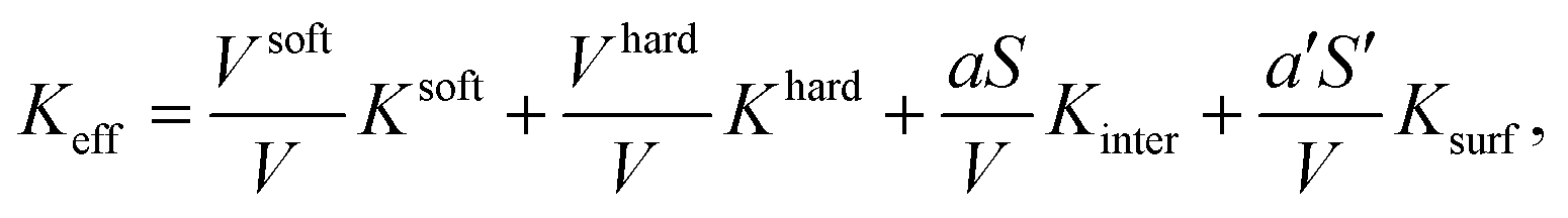
Monodomain magnetic nanoparticles (MNPs) have a strong interest both in fundamental and applied research due to their novel and appealing properties with potential applications in several technological fields, such as engineering (e.g., magnetic recording media or magnetic seals), catalysis and biomedicine.1–3 In particular, significant advances have been made in soft/hard bi-magnetic nanoparticles for hyperthermia and other biomedical applications (e.g. magnetic resonance imaging (MRI), on-demand drug release and target drug delivery).4–8 Moreover, the manipulation of a bi-magnetic core/shell nanoarchitecture is a powerful tool for obtaining new functionalities in a single nanoscale object.5–12 This high interest in multifunctional nanoscaled core/shell systems has triggered substantial synthetic advances combining both nanoparticle synthesis and surface functionalization.13–15Precise control of morpho-structural features (i.e. size of the core, thickness of the shell) and chemical composition of the core/shell MNPs adds the necessary degrees of freedom to control magnetic properties for specific applications. The fine tuning of coercivity and blocking temperature has been achieved by the modulation of the morphology (i.e., core or shell) of soft and hard materials.7,16–20 Although the general trend of the simple linear dependence (additivity) of the coercivity on the volume ratio of materials holds for the hard/soft system, it was observed that it breaks for the inverted soft/hard system.17 As was reported by Song and Zhang,17 the linear trend is oversimplified and does not take into account magnetisation reversal processes which are expected to be different when the order of shell and core materials changes. Moreover, the significant contribution of the surface spins in the magnetic anisotropy of single magnetic phase CoFe2O4 nanoparticles has been observed.21 For core/shell systems, a phenomenological model considering both surface and interface effects was developed by Trohidou et al. which estimated Keff for a two-phase exchange-coupled nanoparticle system:22
 | (1) |
In core/shell MNPs assemblies, a very important but not efficiently explored issue is the interplay between intra- and interparticle interactions and their influence on the macroscopic magnetic properties of the system. Ming Da Yang et al.,23 demonstrated that modulating interparticle interactions in core/shell systems results in the stabilisation of suspension properties, thus increasing the heating performance in hyperthermia as well as R2 relaxivity for contrast enhancement in MRI. Samuel D. Oberdick et al. employed theoretical calculations and showed that the Dzyaloshinskii–Moriya interactions were responsible for the experimentally observed spin canting in bi-magnetic Fe3O4/MnxFe1−xO4 (x > 0.8) particles.24 Moreover, interparticle interactions lead to the correlation of spin canting angle between neighbouring particles. Thus, the macroscopic magnetic properties of this system are determined by the strong interplay of intra- and interparticle interactions. Theoretical description of interacting bi-magnetic core/shell nanoparticle systems is a complex task due to the need to consider both long-range and short-range interactions. Margaris et al. have developed a mesoscopic scale model to accomplish this task in the case of dipolarly interacting Co nanoparticles surrounded by a thin CoO shell.25 In this study, they showed that the interplay of intraparticle and dipolar and exchange interparticle interactions defined the observed magnetic behavior.
The synthesis and characterisation of bi-magnetic core/shell ferrite nanoparticles with conventional (hard/soft) and inverse (soft/hard) structures are reported and compared with single-phase systems. The ferrites CoFe2O4 (CFO) and NiFe2O4 (NFO) were chosen due to the increasing interest in their applications (e.g., biomedicine, catalysis, etc.26,27) as well as the significant difference between the magnetocrystalline anisotropy, KNFOV = −6.2 × 10³ J m−3 and KCFOV = 2 × 10⁵ J m−3, and the relatively high value of their magnetisation Ms (MCFOs = 88 A m2 kg−1 and MNFOs = 55 A m2 kg−1).28,29 While most works deal with iron oxides or Mn/Zn substituted ferrites as a soft phase, only a few works are devoted to nickel ferrite in core/shell systems,4,14,30 although nickel ferrite being a promising material for catalysis31 and spintronics32 applications.
In this context, the paper focuses on the interplay between inter- and intraparticle interactions in core/shell systems. We approach this issue by studying the magnetization reversal mechanisms in terms of the switching field distribution (SFD),33 and the anisotropy energy barrier distribution.34–36 Finally, Monte Carlo simulations were performed on interacting assemblies of these core/shell nanoparticles taking into account intraparticle (i.e. interface and surface effects) and interparticle interactions. A mesoscopic model has been developed considering each nanoparticle with the minimum number of spins necessary to describe its morphology. This model includes for each particle four spins and it considers the actual size of the magnetic moments for each region, the actual contribution of the volume anisotropies in each region and the interparticle interactions. To the best of our knowledge, it is the first attempt to apply a mesoscopic theoretical model for core/shell magnetic nanoparticles system including interface and surface effects to investigate the proximity effects and how these effects modulate the interparticle interactions. We compare the findings of the model with the experimental results.
2. Experimental section
2.1 Synthesis
Iron(III) acetylacetonate (97%), cobalt(II) acetylacetonate (97%), and nickel(II) acetylacetonate (95%) were purchased from Alfa Aesar. Oleic acid (technical grade, 90%), oleylamine (technical grade, 70%), 1,2-hexadecanediol (90%), benzyl ether (99%), toluene, 2-propanol, and acetone were purchased from Sigma Aldrich and used without further purification.In the present work, all the syntheses were conducted under oxygen-free conditions in a Schlenk line. The synthesis of core/shell nanoparticles was carried out using a two-step procedure in which preformed Co or Ni ferrite nanoparticles were used as seeds for the subsequent growth of Co or Ni ferrites. The core was synthesised using a modified procedure reported elsewhere.37 For example, to obtain the CoFe2O4, Fe(acac)3 (2 mmol, 0.706 g), Co(acac)2 (1 mmol, 0.267 g), 1,2-hexadecanediol (10 mmol, 2.58 g), oleic acid (6 mmol, 1.69 g) and oleylamine (6 mmol, 1.60 g), were dissolved in benzyl ether (20 mL) and magnetically stirred under a flow of nitrogen. The mixture was heated (5 °C min−1) up to 200 °C for 100 min and then heated (5 °C min−1) to reflux (≈300 °C) for 60 min. The black-coloured mixture was left to cool to room temperature (RT ≈ 25 °C) and washed with toluene and isopropanol. Next, the precipitate was washed with ethanol and collected by centrifugation (4000 rpm, 10 min). The washing with ethanol was repeated three times in total.
A seed-mediated growth at high temperature was used to achieve core/shell nanoparticles. For example, for CoFe2O4/NiFe2O4 MNPs, cobalt ferrite seeds were sonicated in 5 mL benzyl ether in the presence of oleic acid (600 μL): then, the suspension was added to the flask containing Ni(acac)2 (0.33 mmol, 0.0848 g), Fe(acac)3 (0.67 mmol, 0.237 g) and oleic acid (600 μL) were dissolved benzyl ether (15 mL). After 1 h under vacuum at RT, the solution was heated to reflux at 290 °C (5 °C min−1) under argon atmosphere and kept at this temperature for 30 min. The black-coloured mixture was left to cool to RT and magnetically washed overnight with toluene and isopropanol. Next, the precipitate was washed with ethanol and collected by centrifugation (4000 rpm, 10 min). The washing with ethanol was repeated three times in total.
2.2 Characterisation and data elaboration
The X-ray diffraction (XRD) patterns collected on dried powders were obtained by a Bruker DaVinci2 diffractometer using Cu Kα (λ = 1.54056 Å) radiation in the 10°–75° 2θ range. The mean size of crystallites, dXRD, was obtained by using Scherrer's equation: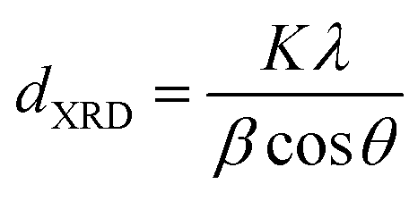 | (2) |
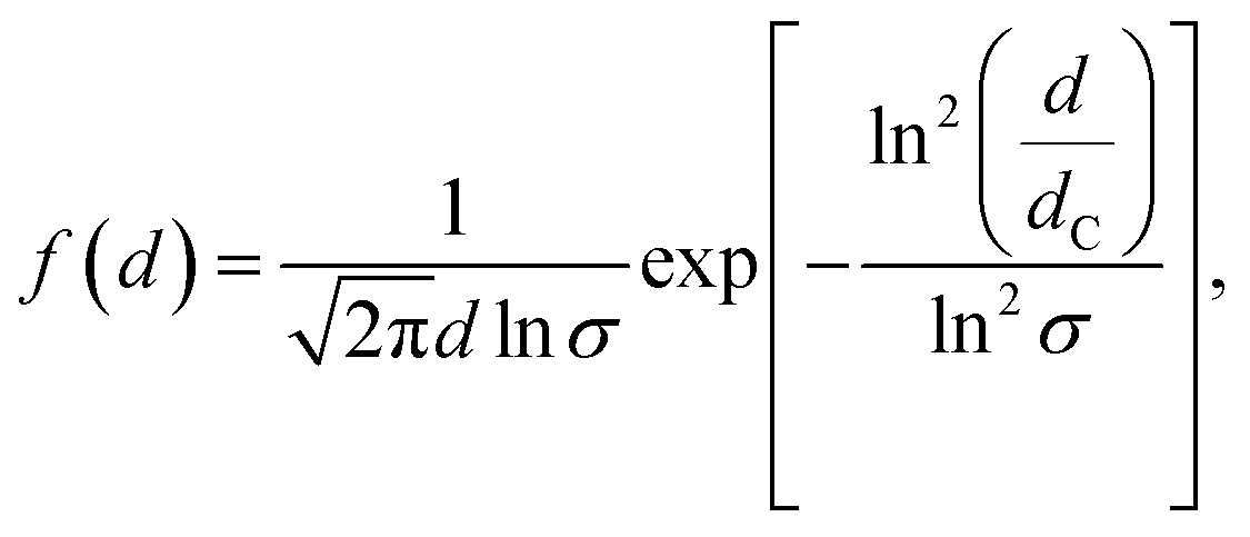
Scanning Transmission Electron Microscopy (STEM) was used to investigate the size distribution and morphology of the particles by means of a Hitachi S5500 STEM operating at 30 kV. Finely ground samples were dispersed in ethanol and submitted to an ultrasonic bath. The suspensions were then dropped on carbon-coated copper grids for the STEM observations. A log-normal function38 was fitted to the particle size distribution obtained by STEM image analysis:
 | (3) |
The TEM images and EFTEM (Energy Filtered TEM) maps used to identify elemental distribution with nanometric resolution inside the core/shell MNPs were collected by a ZEISS LIBRA 200FE-HR TEM, operating at 200 kV and equipped with a second generation in-column Ω filter. Elemental maps of the elements were recorded at 708 eV, corresponding to the iron L3 white line, at 779 eV corresponding to the cobalt L3 white line, and at 855 eV, corresponding to the nickel L3 white line, using an energy window of 12 eV. The images were processed by means of the TEM Imaging Platform software (Olympus). The samples were prepared by dropping 7 μL of core/shell MNP suspension on a copper grid, coated with a carbon ultrathin film (3–5 nm thick), and let it dry overnight.
The DC magnetisation measurements were performed by a quantum design superconducting quantum interference device (SQUID) magnetometer (μ0Hmax = 5 T). Since after synthesis some surfactant (oleic acid, oleylamine) remains bound to the surface of the particles, the mass of the inorganic component of the samples was measured by thermogravimetric analysis and the magnetisation was calculated with respect to the inorganic component. The sample in the form of a powder was immobilised in epoxy resin to avoid any movement of the nanoparticles during the measurements, which can distort the shape of the hysteresis loop and eliminate remanence effects following elaboration of data.39,40 Hysteresis loops were obtained in a −5/+5 T applied magnetic field at temperatures from 5 to 300 K. The value of saturation magnetization (Ms) was estimated by law of approach to saturation (i.e., H: M = Ms(1 − A/H − B/H2), where A and B are free parameters) to high values of fields.41
The magnetic study of the interparticle interactions was performed at 5 K by field dependent remanent magnetization.42 The isothermal remanent magnetisation (IRM) was obtained starting from a totally demagnetised state. A positive magnetic field (μ0HR) was applied for 10 s, then removed and the remanence MIRM(H) was measured. The process was repeated, increasing the field up to 5 T. In the direct current demagnetisation (DCD) measurements, the sample has been saturated at −5 T; then positive magnetic field was applied and, after 10 s, it was switched off and the remanent magnetization was measured. This was repeated, increasing the field up to 5 T. Then the ΔM-plot was plotted and analysed.36,42–44 Qualitative analysis of interparticle interactions is based on the calculation of the interaction field μ0HINT as half the difference in the position of the maxima (μ0HCr) of the derivatives dMDCD(H)/dH and dMIRM(H)/dH.
The thermal dependence of magnetization was investigated by the zero field cooled (ZFC) and field cooled (FC) protocols. In ZFC protocol the sample was first cooled down from 300 to 5 K in zero magnetic field, then a static magnetic field of 2.5 mT was applied and MZFC was measured during warming up. In FC protocol the sample was cooled down to 5 K under the same magnetic field and MFC was measured during the cooling.
2.3 The mesoscopic model
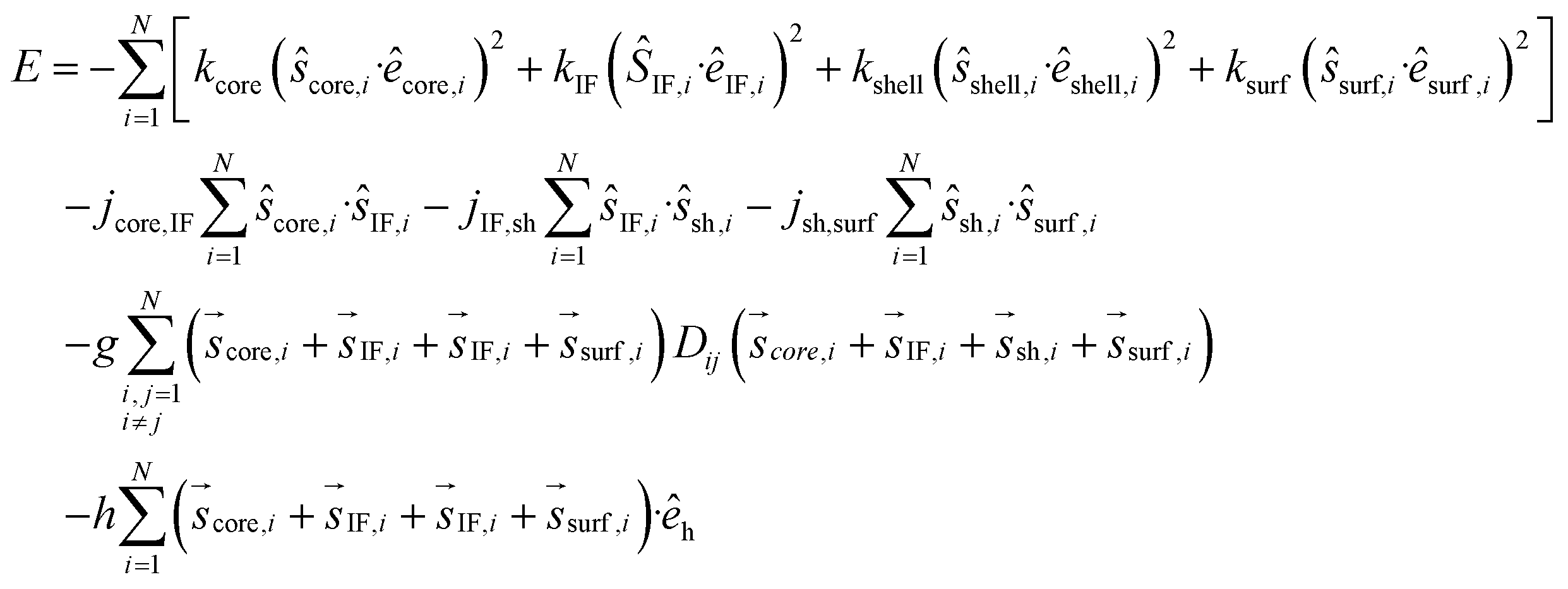
We consider a dense assembly of N identical spherical particles (concentration 50%) of core size dcore = 8.6 nm and shell thickness 3.25 nm. The particles of the assembly are placed randomly at the nodes of a simple cubic lattice, inside a cubic box of dimensions 10α × 10α × 10α, where α is the smallest interparticle distance. We have developed a new mesoscopic model that includes four macro spins for the description of each nanoparticle in the assembly, in this way we explicitly include surface and interface effects. Interparticle dipolar interactions are also included in our model (Fig. 1). | ||
| Fig. 1 Schematic representation of a system of dipolarly interacting core/shell nanoparticles. The nanoparticle architecture (soft/hard or hard/soft) defines the strength of the exchange intraparticle interactions (jcore-IF, jIF-sh, jsh-surf) between the four macro-spins (score, sIF, sshell, ssurf) for the core, shell, interface and surface regions respectively, in the mesoscopic model. Each spin also interacts with the spins of the neighbouring nanoparticles via dipolar interactions. | ||
Each nanoparticle in the assembly consists of four regions as in an atomic scale model:45 the core, the interface (including both the core and shell interface), the shell and the surface. The four regions are represented by a set of four classical macro spins vectors: ![[s with combining right harpoon above (vector)]](https://www.rsc.org/images/entities/i_char_0073_20d1.gif) core, IF, shell, surf. The size of these spins in each assembly is given in Table 1 and it is calculated as sregion = Ms,region·Nregion/Ms,core·Ncore. Here Nregion is the number of spins in each of the above particle regions and Ms,core, Ms,shell the bulk magnetisation of the core and the shell in the CFO/NFO and NFO/CFO systems. In our model for pure CoFe2O4 or NiFe2O4 nanoparticles, we consider two regions, the core and the surface, consequently, we use two macro spins, one for the core and one for the surface to describe them.
core, IF, shell, surf. The size of these spins in each assembly is given in Table 1 and it is calculated as sregion = Ms,region·Nregion/Ms,core·Ncore. Here Nregion is the number of spins in each of the above particle regions and Ms,core, Ms,shell the bulk magnetisation of the core and the shell in the CFO/NFO and NFO/CFO systems. In our model for pure CoFe2O4 or NiFe2O4 nanoparticles, we consider two regions, the core and the surface, consequently, we use two macro spins, one for the core and one for the surface to describe them.
| Sample | Size of macro spins | Anisotropy constant | ||||||
|---|---|---|---|---|---|---|---|---|
| s core | s IF | s shell | s surf | k core | k IF | k shell | k surf | |
| CFO | 0.796 | 0.0 | 0.0 | 0.204 | 0.8 | 0.0 | 0.0 | 2.6 |
| CFO/NFO | 0.796 | 0.396 | 2.642 | 0.473 | 0.8 | 2.73 | 0.087 | 3.12 |
| NFO | 0.796 | 0.0 | 0.0 | 0.204 | 0.019 | 0.0 | 0.0 | 0.095 |
| NFO/CFO | 0.796 | 0.509 | 4.912 | 0.88 | 0.019 | 2.974 | 3.6024 | 0.774 |
In all cases, the number of spins in each region is calculated from an atomic scale model for each nanoparticle, reproducing the geometry of the inverse spinel structure and taking into account the dimensions of the nanoparticle in the assembly. We consider a random anisotropy assembly, so that each particle is assigned a randomly oriented uniaxial easy axis, common to all four spins in the particle.
The effective anisotropy constants of the four spins have been calculated as kregion = Kregion·Vregion/Kcore·Vcore where Kregion and Vregion are the anisotropy energy density and the volume of the corresponding region. Kcore, and Kshell are taken to be the values of the bulk for CoFe2O4 and NiFe2O4 in each case,46 the values of Kcore,IF and Kshell,IF are 13 times larger than the core bulk values due to interface effects (proximity effects, local frustration) expressing the strong coupling between the two phases. In the case of pure CoFe2O4 and NiFe2O4 nanoparticles, Ksurf is taken to be 13 and 20 times larger than the corresponding bulk values of the core material respectively due to surface effects, in agreement with our experimental estimations of the enhanced effective anisotropy, Keff, of the samples. Accordingly, for the NiFe2O4 core/CoFe2O4 shell, the Ksurf is taken to be 1.2 times larger than the hard Kshell. For the CoFe2O4 core/NiFe2O4 shell, Ksurf is taken to be 200 times larger than the soft KV,shell because of the proximity effect with the hard core which induces a higher anisotropy in the nickel ferrite when it grows on more magnetically hard cobalt ferrite seeds, justifying the high experimental coercive field value. The values of the anisotropy constants in the above regions are also listed in Table 1 for the corresponding systems.
In our simulations, we divide the energy terms of the four systems with the energy term kcr = Kcore·Vcore, where Kcore is the bulk CoFe2O4 core anisotropy, so our energy terms are dimensionless. In our model, in each nanoparticle, Heisenberg exchange interactions have been considered between nearest neighbour regions, namely: (a) between the bulk-core spin and the interface spin (jcore-IF), (b) between the interface spin and the bulk-shell spin (jIF-sh) and (c) between the bulk-shell spin and the surface spin (jsh-surf). We assume that these intraparticle exchange strengths are proportional to the surface area of contact between the two regions and not to their volume. Since in the literature there is no calculation for the interface exchange coupling, we consider the exchange coupling jcore-IF as a free parameter and we set it equal to two for CFO and equal to 1.25 for the NFO system. We calculate the other two exchange parameters by multiplying each of them by the ratio of the shell and the surface respectively to the core-interface region. Thus jIF-sh = 2.22 and jsh-surf = 6.34.
Moreover, since the particles are coated with an oleic acid surfactant, they interact in the assembly only via long-range dipolar forces. Each spin in a particle interacts with all the spins in all the other particles in the assembly. The reduced dipolar interaction strength is calculated using the expression g = μ0Ms,core2/24Kcore (Dcore/α)3 where Ms,core is the core saturation magnetisation MCFOs,core = 0.45 MA m−1 and MNFOs,core = 0.33 MA m−1.46 For a random monodisperse dense assembly α ≈ dparticle so for the pure CoFe2O4, CoFe2O4/NiFe2O4 core/shell, pure NiFe2O4 and NiFe2O4/CoFe2O4 core/shell the calculated dipolar energy values are 0.0236, 0.0044, 0.0197, 0.0036 respectively.
The external magnetic field is defined as h = (μ0Ms,core·Ncore/Kcore·Vcore)·H and the thermal energy is denoted by t = kBT/Kcore·Vcore. Including the energy parameters of the anisotropy, the nearest neighbour Heisenberg exchange interactions between the spins in each particle, the dipolar energy and the Zeeman energy terms the total energy of the system is given by the equation:
 | (4) |
It has been demonstrated in the literature that the saturation magnetisation of the ferrite nanoparticles is reduced due to the spin canting effect. This spin canting decreases with the increase of the temperature47 or the increase of the external applied field24 and depends on the size and the method of production of the nanoparticles.47–51 Thus, in our calculations of the low temperature hysteresis loops, spin canting effects are introduced by estimating a 15% and 30% reduction of the surface magnetization for the pure CoFe2O4 and NiFe2O4 nanoparticles respectively. Accordingly, in the case of CoFe2O4 core/NiFe2O4 shell particles, we consider a reduction in magnetisation of 15% at the interface and 30% at the surface. However, in the case of NiFe2O4 core/CoFe2O4 shell particles, we assume a very small magnetisation reduction at the interface (0.5%) and the surface (1%) because the large hard shell (82% volume ratio) dominates over the spin canting effects at the interface with the soft core material and at the surface.17
Monte Carlo simulations using the standard Metropolis algorithm52 were performed to calculate the hysteresis loops, the demagnetization DCD (mDCD) and isothermal remanence IRM (mIRM) curves at a low temperature (t = 0.01) following the same procedure as in the experimental situation as described in Section 2.2. For the dipolar energy calculation, the Ewald summation technique has been implemented taking into account the long-range character of the dipolar interactions, using periodic boundaries in all directions and Dij is the dipolar interaction tensor.25,53 The Monte Carlo simulations result for a given temperature and applied field were averaged over 10 samples with various spin configurations, easy-axis distribution and different spatial configurations for the nanoparticles.
3. Results and discussion
X-ray diffraction patterns (ESI, Fig. S1†) show the main reflections of the cubic spinel structure for all the samples (PDF cards 22-1085 and 44-1485). No other phase than that of the spinel ferrite has been detected, because CFO and NFO have spinel structure with very close lattice constants (a = 0.838 nm for CFO and a = 0.834 nm for NFO54) and the crystallite size of both phases is in the few nm range, causing a similar broadening of peaks, the diffraction patterns of the CFO and NFO phases cannot be distinguished by means of a benchmark powder XRD instrument. The crystallite sizes were calculated by the Scherrer's formula (eqn (2)) on [400] reflections as reported in Table 2 (we did not use the [311] peak because it is superimposed to the [222] peak). The larger structural correlation length of the core/shell samples induce to believe that the shell grows epitaxially onto the core. The electron diffraction pattern of CFO/NFO sample shows the rings typical for the spinel ferrite nanocrystallites (ESI, Fig. S2†).| Sample | Composition | d C, nm | a, nm | V hard/Vd | ||
|---|---|---|---|---|---|---|
| STEMb | SDb | XRDc | ||||
| a The error in the last digit is reported in parenthesis. b Median diameter of the particle (dC) and standard deviation (SD) of best-fit log-normal size distribution. c Crystallite size calculated using Scherrer formula for [400] reflections. d The volume of phases was calculated by assuming spherical particles. | ||||||
| CFO | CoFe2O4 | 6.9(1) | 0.9 | 6.2(2) | 0.840(1) | 1 |
| CFO/NFO | CoFe2O4@NiFe2O4 | 11 | 3 | 9.2(4) | 0.838(1) | 0.3 |
| NFO | NiFe2O4 | 8.4(2) | 1.8 | 6.2(4) | 0.838(1) | 0 |
| NFO/CFO | NiFe2O4@CoFe2O4 | 12 | 2 | 9.0(2) | 0.837(1) | 0.6 |
The analysis of STEM images confirms the presence of the rounded particles with high crystallinity (Fig. 2). Median particle diameter (dc) and standard deviations (SD), calculated by the log-normal fitting of diameter distribution with eqn (3) (Fig. 2e, f and Table 2), indicate, within experimental error, that the sizes in both the single phases and in both core/shell structures are comparable. It is worth underlining that both core/shell samples are about 2 nm larger than the corresponding seeds. In conjunction with the XRD results above, the STEM data confirm the growth of a ∼2 nm shell around the seeds. Additional confirmation of the core/shell structure is provided by TEM energy-filtered elemental maps (Fig. S3†). Also, an increase in SD was observed after the treatment of CFO to form CFO/NFO MNPs and, on the contrary, a reduction of SD was observed in the formation of the inverted system, i.e. from NFO to NFO/CFO MNPs.
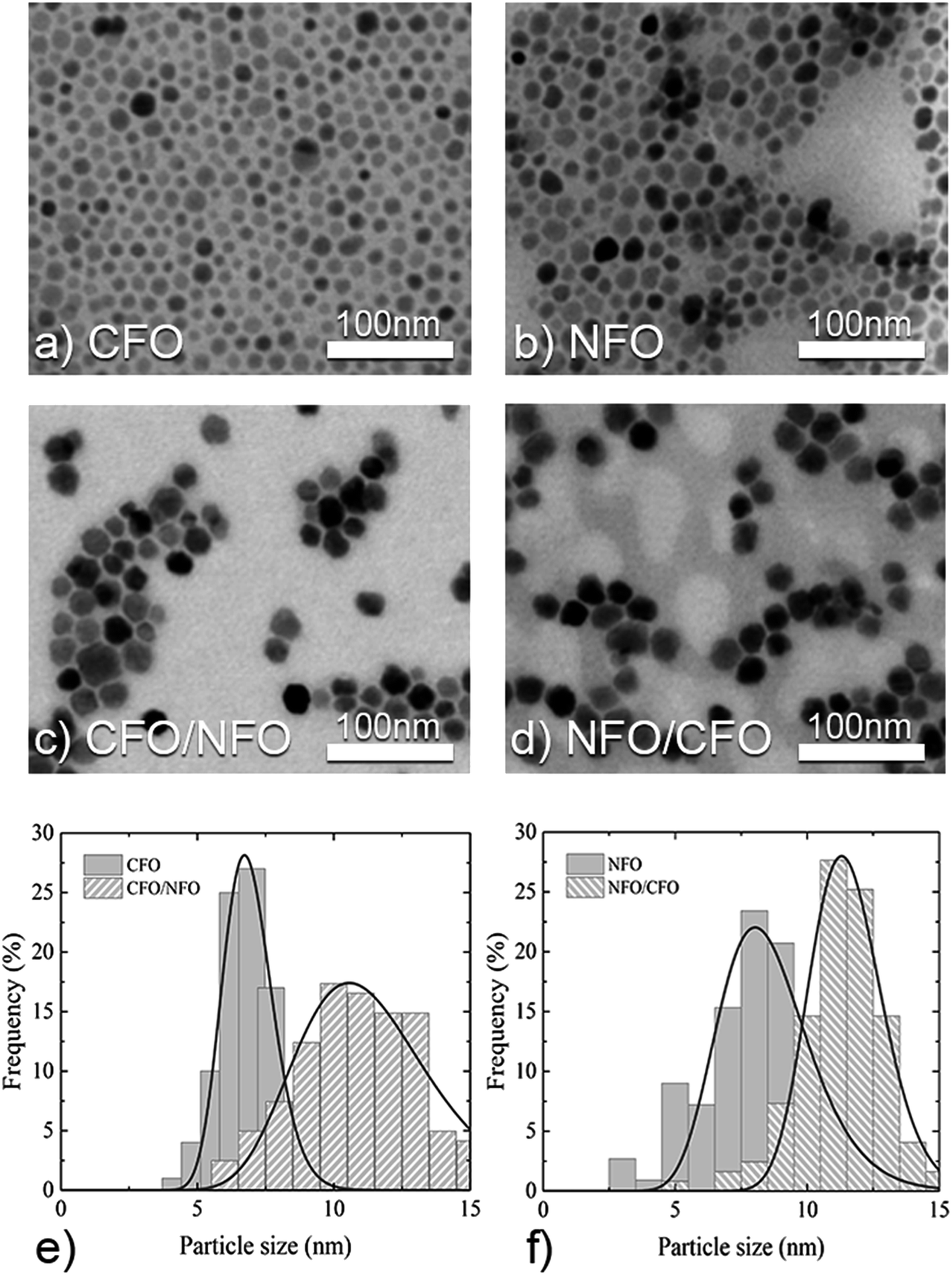 | ||
| Fig. 2 STEM images of (a) CFO and (b) NFO seeds; (c) CFO/NFO and (d) NFO/CFO core/shell NPs. Histograms of size distribution: (e) CFO and CFO/NFO; (f) NFO and NFO/CFO. Fitting of size distribution by the log-normal function is present by the solid line. The scale bar of STEM images is 100 nm. | ||
The field dependence of magnetisation recorded at 5 K (Fig. 3) shows hysteretic behaviour. All the extracted magnetic parameters (i.e. coercivity, μ0Hc; saturation magnetization, Ms; and reduced remanent magnetisation, Mr/Ms) are reported in Table 3. The observed values of Ms (i.e., ∼98 and ∼75 A m2 kg−1 for CFO and NFO) are higher than the bulk values (88 and 55 A m2 kg−1 at 5 K for bulk cobalt ferrite and nickel ferrite, respectively) probably due to some difference in magnetic structure (i.e., cationic distribution and surface effect) at the nanoscale. It is interesting to underline that, for both core/shell samples, the Ms values are very close to the mean of the magnetisation of two materials weighted by the volume composition. The monotonic shape of the hysteresis loops of the core/shell CFO/NFO MNPs, without any anomalies around zero field,55 suggests a strong coupling between the hard core and the soft shell phases.17 In all samples, the reduced remanent magnetisation increases going from the single phase to the core/shell system. CFO show Mr/Ms ≅ 0.47 and an evident increase is observed in CFO/NFO system (Mr/Ms ≅ 0.61) approaching the theoretical value of ∼0.83 expected for single-domain non-interacting particles with cubic magnetic anisotropy.41 The lower value of Mr/Ms of ∼0.21 for NFO (theoretical value of ∼0.5 for uniaxial particles41) can be ascribed to the presence of a fraction of still relaxing particles at 5 K, due to the presence of inter-particle interactions or to some effect due to a demagnetising field.56 A significant increase in Mr/Ms is observed in NFO/CFO core/shell systems. Curiously, the largest Mr/Ms (i.e., the tendency to cubic anisotropy) has been observed for the system with a higher volume of nickel ferrite (sample CFO/NFO), which is expected to have the lower magnetocrystalline anisotropy. Indeed, usually cobalt ions induce dominating cubic-type effective magnetic anisotropy because of strong magnetocrystalline anisotropy57). This can be ascribed to the proximity effects that increase anisotropy in nickel ferrite when it grows on magnetically harder cobalt ferrite seeds due to the induced strong pinning of interfacial spins.58,59 In contrast, a smaller Mr/Ms was observed in the system with the predominant cobalt ferrite volume.
 | ||
| Fig. 3 Hysteresis loops recorded at 5 K for (a) CFO and CFO/NFO; (b) NFO and NFO/CFO samples. In the inset of both figures, the low-field region of M–H cycles at 300 K is presented; Monte Carlo simulation results for the hysteresis loops at t = 0.01 of dipolarly interacting assemblies of (c) CFO and CFO/NFO and (d) NFO and NFO/CFO nanoparticles. | ||
| Sample | M s,b A m2 kg−1 | μ 0 H c, T | μ 0 H irr, T | M r/Ms | T B, K | K eff,c ×105 J m−3 | E dip/kB,dK | H INT/Hc (%) |
|---|---|---|---|---|---|---|---|---|
| a The error in the last digit is reported in parenthesis. b The value of Ms obtained at 5 K with the fitting of high field region with equation M = Ms·(1 − a/H − bH2), the value in brackets is the fitting error. c The Keff is calculated following eqn (5). d The estimated error for the Edip is about 20%. | ||||||||
| CFO | 98(5) | 1.3(2) | 3.2(2) | 0.47 | 175(5) | 8.3(2) | 44 | −6 |
| CFO/NFO | 83(3) | 0.83(1) | 1.8(1) | 0.61 | 174(4) | 3.9(2) | 198 | −2 |
| NFO | 75(3) | 0.025(1) | 0.3(1) | 0.21 | 28(3) | 0.6(1) | 57 | −33 |
| NFO/CFO | 86(3) | 0.30(1) | 1.3(1) | 0.45 | 173(4) | 2.9(1) | 295 | −2 |
The coercive field (μ0Hc) and the irreversibility field, (μ0Hirr), (i.e., the point at which the difference between the magnetising and demagnetising branches is below 3% of their maximum value60), of the CFO sample were reduced when it was covered with a softer nickel ferrite shell (CFO/NFO sample). On the contrary, μ0Hc and μ0Hirr of NFO/CFO were increased with respect to NFO seeds (Table 3). Notably, the design of the magnetic nanoarchitecture (i.e. relative position (core or shell) of soft and hard materials) plays a crucial role in their effective magnetic anisotropy. Indeed anisotropy estimated from eqn (1) without consideration of surface and interface effects predicts a different trend.
Fig. 3 shows the Monte Carlo simulation results for the low temperature (t = 0.01) hysteresis loops for the assemblies of CFO and CFO/NFO (Fig. 3c) and the NFO and NFO/CFO (Fig. 3d) systems. The simulated hysteresis loops of core/shell particles are also smooth, indicating a strong exchange coupling between the two phases in agreement with the experimental findings. The proximity effect at the interface between the CFO core and NFO shell enhances the anisotropy of the shell component resulting in a coercive field value higher than that of the NFO/CFO system. On the other hand, the proximity effect of the CFO shell and NFO core enhances the coercive field of the pure NFO sample by a factor of almost 13. Our Monte Carlo simulations are in good qualitative agreement with the experimental results, indicating that the magnetic properties core/shell systems are tuned via proximity effects.
M–H curves measured at 300 K (inset Fig. 3a and b) show completely reversible behaviour (i.e., Mr = 0, Hc = 0) suggesting that all the samples are in the superparamagnetic state at room temperature. To better understand the magnetic properties of these systems, their magnetothermal behavior has been also investigated.
The ZFC and FC magnetisation curves for both single phase and core/shell samples (Fig. S4†) showed typical behaviour of interacting mono-domain particles with different anisotropy (see details in the ESI†). An estimation of the distribution of anisotropy energy (DAE) barriers can be obtained by the −dMFC-ZFC(T)/dT curve reported in Fig. 4 (see ESI† for a detailed explanation of the method).21,61 In Fig. 4 the filled areas under the −dMFC-ZFC(T)/dT curves represent the cumulative DAE (eqn (S1)†). Considering the mean blocking temperature (TB) as the temperature at which half of the particles are in the superparamagnetic state, the values of TB for all the samples are reported in Table 3. For the NFO and CFO samples, the different values of the blocking temperature (∼28 and ∼175 K, respectively) can be ascribed to the different magnetocrystalline anisotropy of the NFO and CFO. On the other hand, a significant increase of TB is observed in NFO after the coverage with the CoFe2O4, the same value of TB within an experimental error was also observed for the CFO and CFO/NFO samples.62
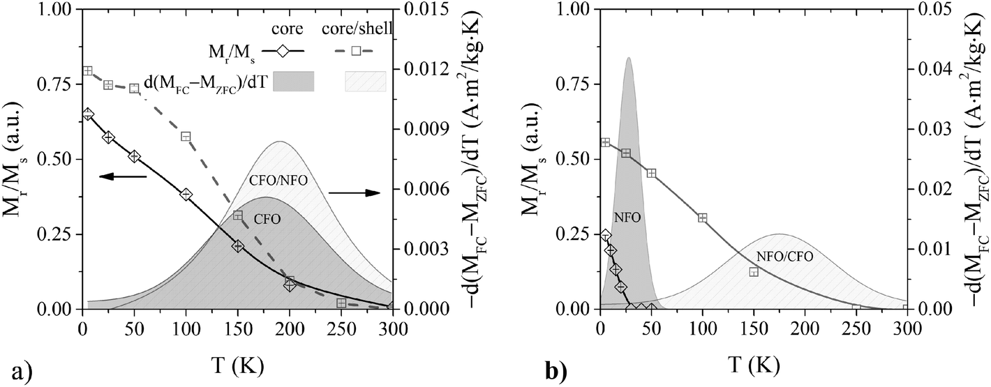 | ||
| Fig. 4 The diamond and square symbols are the reduced remanent magnetization at different temperatures for core and core/shell samples. The filled areas indicate the integral's value of −dMFC-ZFC(T)/dT curves calculated from the temperature dependence of magnetizations in ZFC and FC protocols in the field of 2.5 mT for (a) CFO and CFO/NFO samples; (b) NFO and NFO/CFO. The error bars are smaller than the size of the symbols. | ||
Fig. 4 shows the temperature dependence of the reduced remanent magnetisation estimated from hysteresis loops recorded at different temperatures. The Mr/Ms trend for all the samples substantially confirms the landscape obtained by DAE. The Mr/Ms vanishes at the upper limit of the DAE where the entire system is in the superparamagnetic state for T ≥ Tirr. The only exception is the NFO sample for which Mr/Ms vanishes at lower temperatures, closer to TB.
Following the Stoner and Wohlfarth model63 and assuming negligible magnetic interparticle interactions,36,60,64 the anisotropy constant can be defined as:
| Keff = μ0HKMs/2. | (5) |
It can be considered that μ0HK ≈ μ0Hirr, an approximation first suggested by Kodama et al. for NiFe2O4 nanoparticles,65 which has also been used for other similar nanoparticle systems.36,66,67 The trend in anisotropy constants' values follows qualitatively the trend of the coercive and irreversibility fields' values, confirming the efficiency of interface coupling in tuning the anisotropy.
3.1 Magnetic inter- and intraparticle interactions
For a more detailed study of the interparticle interactions, the field dependence of the remanent magnetisation has been investigated at 5 K by IRM and DCD protocols (Fig. S5†). The differentiated remanence curve, (i.e. dMIRM(H)/dH, Fig. S5†) represents the irreversible component of the susceptibility. This quantity can be considered as a measure of the energy barriers distribution, which, in a nanoparticle system, is associated with the switching field distribution (SFD).68,69 The field, corresponding to the mean SFD value, is called remanence coercivity (Hcr) and it represents the coercive field of the particles in the blocked state, which are responsible for the irreversible part of the magnetization. For a system of Stoner–Wohlfarth particles, the SFD can be considered proportional to the distribution of the particle’ individual magnetic moment switching in an external magnetic field close to its anisotropy field. Thus, for particle systems with equivalent volume distributions f(V), deviations in the shape of SFD will reflect in differences in the distribution of Ms or K in addition to the effect of particle size distribution.As it is expected, the HCr (Fig. 5a) has the same trend of μ0Hc and μ0Hirr and Keff. It is interesting to note that SFD, normalised in X-axis by corresponding HCr and in Y-axis by Mr (Fig. S6†), shows that the seed-mediated growth of the shell does not generate new factors which would broaden the distribution of magnetic properties. Indeed, the standard deviation of the SFD for both core/shell systems does not exceed those of the corresponding seeds, Table S1†). In addition, it appears that the magnetically softer samples NFO seeds and NFO/CFO core/shell particles have a higher dispersion than that of the CFO sample. This is consistent with the observed higher SD from TEM measurements and the expected stronger influence of the surface effects in magnetically softer nanoparticle samples. On the other hand, by comparing both core/shell systems, one can note that the SFD is broader in the NFO/CFO sample than in the CFO/NFO sample, while the SD from TEM analysis has the opposite trend. This behavior can be explained by the dominant role of the magnetically harder counterpart (CFO core), governing the magnetisation processes in the CFO/NFO system.
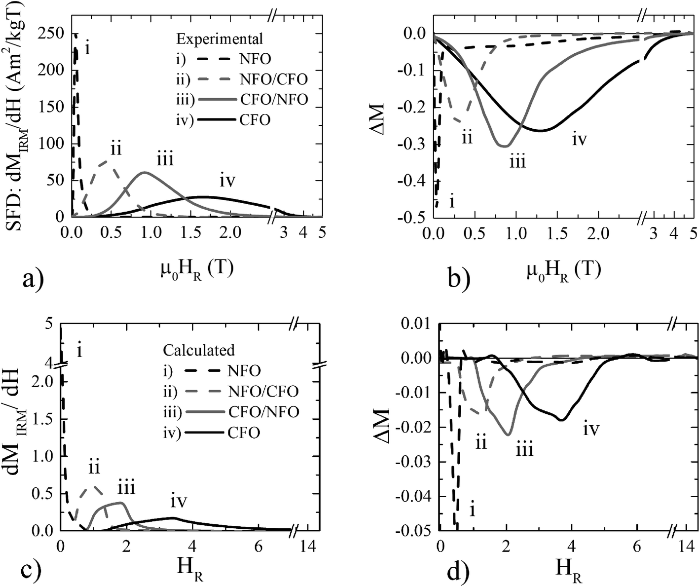 | ||
| Fig. 5 (a) Switching field distribution (SFD) plotted as the first derivate of MIRM(H) and (b) ΔM-plot measured at 5 K; Monte Carlo results at t = 0.01 for: (c) Switching Field Distribution (SFD) and (d) ΔM-plot of the dipolary interacting assemblies of NFO, CFO, CFO/NFO and NFO/CFO nanoparticles. | ||
According to the Stoner–Wohlfarth model,42,70 for an assembly of non-interacting uniaxial single-domain particles, the remanent magnetisation recorded by DCD and IRM protocols are linearly related (mDCD(H) = 1 − 2MIRM(H)). Two factors may cause deviations from this trend: (i) interparticle interactions and/or (ii) multiaxial anisotropy.36,44 For the analysis, we have used the Henkel plots modified by Kelly (ΔM-plot):71
| ΔM(H) = mDCD(H) − 1 + 2 MIRM(H) | (6) |
A negative contribution to the ΔM-plot indicates the dominant demagnetizing character of dipolar interactions between particles; a positive contribution, on the contrary, is caused by the dominant “positive” magnetizing character of the exchange interactions.44 The ΔM-plots (Fig. 5b) in all samples show negative values. For both core/shell systems and CFO samples, the absolute value of the |ΔM| dip is in the range 0.2–0.3 while for NFO samples this value is almost twice as large reaching ∼0.45 indicating that for NFO samples interparticle interactions play a significant role. The interaction field μ0HINT (i.e., (μ0HDCDCr − μ0HIRMCr)/2) shows negative values for all seed and core/shell systems confirming the dipolar interparticle interactions role. The ratio HINT/Hc shows the effect of the interparticle interactions compared with the coercive field (Table 3). These values are relatively low except in the case of the magnetically softer NFO seeds, where the intrinsic anisotropy is very small. The absolute value of dipolar interaction energy (Table 3) has been roughly estimated using Edip ≈ μ0μ2/4πd3 (where d is the average distance, which at first approximation is the diameter of the particles plus the thickness of two monolayers of oleic acid (one on each particle) each of them has thickness ∼2 nm).57 This calculated Edip cannot explain the picture of the interparticle interactions described by the ΔM-plot. We attribute the observed magnetic behavior to the complex interplay between intraparticle and interparticle interactions. This is further confirmed by the calculated SFD and ΔM-plots (Fig. 5c and d), showing very good qualitative agreement with the experimental results (Fig. 5a and b). To determine the relative contribution of the dipolar interparticle interactions and the interface exchange coupling, ΔM-plot in the absence of the dipolar interparticle interactions (g = 0) has been calculated. The results are shown in Fig. 6 for g = 0 (dotted lines) and g ≠ 0 (solid lines) for the CFO/NFO (black) and the NFO/CFO (red) core/shell nanoparticle systems. The results for the g = 0 case, where a small but significant negative ΔM still exists, show the contribution of intraparticle interactions (core/shell structure) in the ΔM-plots in agreement with the findings of ref. 72 and refs therein.
 | ||
| Fig. 6 Monte Carlo simulation results for the ΔM-plots of the dipolarly interacting assemblies (solid lines) of CFO/NFO (black) and NFO/CFO (red) core/shell nanoparticles together with the non-interacting ones (g = 0) (dash-dotted lines). | ||
4. Conclusions
In this work, the synthesis and the magnetic characterisation of core/shell nanoparticles obtained both in hard/soft and inverse soft/hard configurations are presented and discussed. The shell formation was confirmed by an increase of the particle sizes, observed by TEM imaging, and by TEM energy-filtered elemental maps. For both core/shell systems, hysteresis loops at 5 K indicate the presence of a strong magnetic coupling between the core and the shell. The growth of a soft nickel ferrite magnetic shell affects the hard properties of the cobalt ferrite seeds with a decrease of μ0HC from ∼1.3 to 0.8 T. On the contrary, the magnetically harder cobalt ferrite shell increases the coercivity of the soft seeds from ∼0.025 to 0.03 T. Nevertheless, these changes cannot be explained by a classical additive rule.A new 4-spin mesoscopic theoretical model has been implemented to describe interacting core/shell magnetic nanoparticles including surface and interface effects in order to investigate the interplay between intraparticle and interparticle interactions in these systems (Fig. 1). By comparing experimental and Monte Carlo simulations results, we have shown that the magnetic properties of bi-magnetic core/shell nanoparticles assemblies depend both on the intraparticle interfacial exchange coupling and interparticle dipolar interactions and their interplay. The interfacial exchange coupling is the signature of true core/shell nanoparticles and it is manifested in the dramatic changes of the magnetic properties, such as the Mr/Ms and the coercivity Hc, and the smooth hysteresis loops observed after shell growth. The interparticle dipolar interactions affect the switching fields of core/shell nanoparticles in the intermediate range (0.5 to 3 T) much stronger than the interfacial exchange coupling. Interestingly, our study suggests that by tuning the effective anisotropy in bi-magnetic nanoparticle systems via proximity effects, a control over the magnetic interactions between particles can also be achieved.
Conflicts of interest
There are no conflicts to declare.Acknowledgements
This work was supported by the European Union's Horizon 2020 Research and Innovation Programme: under grant agreement No. 731976 (MAGENTA). A. O. acknowledges the financial support of the Ministry of Science and Higher Education of the Russian Federation within the program of development of the North-West Mathematical Center for Sofya Kovalevskaya (No. 075-02-2021-1748).References
- V. F. Cardoso, A. Francesko, C. Ribeiro, M. Bañobre-López, P. Martins and S. Lanceros-Mendez, Advances in Magnetic Nanoparticles for Biomedical Applications, Adv. Healthcare Mater., 2017, 1700845, 1–35, DOI:10.1002/adhm.201700845.
- A. G. Roca, L. Gutiérrez, H. Gavilán, M. E. Fortes Brollo, S. Veintemillas-Verdaguer and M. del P. Morales, Design strategies for shape-controlled magnetic iron oxide nanoparticles, Adv. Drug Delivery Rev., 2019, 138, 68–104, DOI:10.1016/j.addr.2018.12.008.
- V. Socoliuc, D. Peddis, V. I. Petrenko, M. V Avdeev, D. Susan-resiga, T. Szabó, R. Turcu, E. Tombácz and L. Vékás, Magnetic Nanoparticle Systems for Nanomedicine — A Materials Science Perspective, Magetochemistry, 2019, 6, 1–36, DOI:10.3390/magnetochemistry6010002.
- S. H. Moon, S. Noh, J. Lee, T. Shin, Y. Lim and J. Cheon, Ultrathin Interface Regime of Core–Shell Magnetic Nanoparticles for Effective Magnetism Tailoring, Nano Lett., 2017, 17, 800–804, DOI:10.1021/acs.nanolett.6b04016.
- M. Vasilakaki, C. Binns and K. N. Trohidou, Susceptibility losses in heating of magnetic core/shell nanoparticles for hyperthermia: a Monte Carlo study of shape and size effects, Nanoscale, 2015, 7, 7753–7762, 10.1039/C4NR07576E.
- J.-H. Lee, J. Jang, J. Choi, S. H. Moon, S. Noh, J. Kim, J.-G. Kim, I.-S. Kim, K. I. Park and J. Cheon, Exchange-coupled magnetic nanoparticles for efficient heat induction, Nat. Nanotechnol., 2011, 6, 418–422, DOI:10.1038/nnano.2011.95.
- V. Pilati, R. Cabreira Gomes, G. Gomide, P. Coppola, F. G. Silva, F. L. O. Paula, R. Perzynski, G. F. Goya, R. Aquino and J. Depeyrot, Core/Shell Nanoparticles of Non-Stoichiometric Zn-Mn and Zn-Co Ferrites as Thermosensitive Heat Sources for Magnetic Fluid Hyperthermia, J. Phys. Chem. C, 2018, 122, 3028–3038, DOI:10.1021/acs.jpcc.7b11014.
- G. C. Lavorato, R. Das, J. Alonso Masa, M.-H. Phan and H. Srikanth, Hybrid magnetic nanoparticles as efficient nanoheaters in biomedical applications, Nanoscale Adv., 2021, 3, 867–888, 10.1039/d0na00828a.
- A. López-Ortega, M. Estrader, G. Salazar-Alvarez, S. Estradé, I. V. Golosovsky, R. K. Dumas, D. J. Keavney, M. Vasilakaki, K. N. Trohidou, J. Sort, F. Peiró, S. Suriñach, M. D. Baró and J. Nogués, Strongly exchange coupled inverse ferrimagnetic soft/hard, MnxFe3−xO4/FexMn3−xO4, core/shell heterostructured nanoparticles, Nanoscale, 2012, 4, 5138, 10.1039/c2nr30986f.
- T. J. Yoon, H. Lee, H. Shao and R. Weissleder, Highly magnetic core-shell nanoparticles with a unique magnetization mechanism, Angew. Chem., Int. Ed., 2011, 50, 4663–4666, DOI:10.1002/anie.201100101.
- M. Vasilakaki, K. N. Trohidou and J. Nogués, Enhanced Magnetic Properties in Antiferromagnetic-Core/Ferrimagnetic-Shell Nanoparticles, Sci. Rep., 2015, 5, 9609, DOI:10.1038/srep09609.
- K. Sartori, G. Cotin, C. Bouillet, V. Halté, S. Bégin-Colin, F. Choueikani and B. P. Pichon, Strong interfacial coupling through exchange interactions in soft/hard core-shell nanoparticles as a function of cationic distribution, Nanoscale, 2019, 11, 12946–12958, 10.1039/c9nr02323b.
- W. Schärtl, Current directions in core–shell nanoparticle design, Nanoscale, 2010, 2, 829, 10.1039/c0nr00028k.
- V. Gavrilov-Isaac, S. Neveu, V. Dupuis, D. Taverna, A. Gloter and V. Cabuil, Synthesis of Trimagnetic Multishell MnFe2O4@CoFe2O4@NiFe2O4 Nanoparticles, Small, 2015, 11, 2614–2618, DOI:10.1002/smll.201402845.
- D.-H. Kim, Y. Tamada, T. Ono, S. D. Bader, E. A. Rozhkova and V. Novosad, The Effect of Ligands on FePt–Fe3O4 Core–Shell Magnetic Nanoparticles, J. Nanosci. Nanotechnol., 2014, 14, 2648–2652, DOI:10.1166/jnn.2014.8471.
- D. Polishchuk, N. Nedelko, S. Solopan, A. Ślawska-Waniewska, V. Zamorskyi, A. Tovstolytkin and A. Belous, Profound Interfacial Effects in CoFe2O4/Fe3O4 and Fe3O4/CoFe2O4 Core/Shell Nanoparticles, Nanoscale Res. Lett., 2018, 13, 67, DOI:10.1186/s11671-018-2481-x.
- Q. Song and Z. J. Zhang, Controlled Synthesis and Magnetic Properties of Bimagnetic Spinel Ferrite CoFe 2 O 4 and MnFe 2 O 4 Nanocrystals with Core–Shell Architecture, J. Am. Chem. Soc., 2012, 134, 10182–10190, DOI:10.1021/ja302856z.
- M. Sanna Angotzi, V. Mameli, C. Cara, A. Musinu, C. Sangregorio, D. Niznansky, H. L. Xin, J. Vejpravova and C. Cannas, Coupled hard–soft spinel ferrite-based core–shell nanoarchitectures: magnetic properties and heating abilities, Nanoscale Adv., 2020, 2, 3191–3201, 10.1039/D0NA00134A.
- Q. Zhang, I. Castellanos-Rubio, R. Munshi, I. Orue, B. Pelaz, K. I. Gries, W. J. Parak, P. del Pino and A. Pralle, Model Driven Optimization of Magnetic Anisotropy of Exchange-Coupled Core-Shell Ferrite Nanoparticles for Maximal Hysteretic Loss, Chem. Mater., 2015, 27, 7380–7387, DOI:10.1021/acs.chemmater.5b03261.
- S. H. Noh, W. Na, J. T. Jang, J. H. Lee, E. J. Lee, S. H. Moon, Y. Lim, J. S. Shin and J. Cheon, Nanoscale magnetism control via surface and exchange anisotropy for optimized ferrimagnetic hysteresis, Nano Lett., 2012, 12, 3716–3721, DOI:10.1021/nl301499u.
- A. Omelyanchik, M. Salvador, F. D’orazio, V. Mameli, C. Cannas, D. Fiorani, A. Musinu, M. Rivas, V. Rodionova, G. Varvaro and D. Peddis, Magnetocrystalline and surface anisotropy in cofe2o4 nanoparticles, Nanomaterials, 2020, 10, 1–11, DOI:10.3390/nano10071288.
- K. N. Trohidou, C. M. Soukoulis, A. Kostikas and G. Hadjipanayis, Size dependence of coercivity of small magnetic particles, J. Magn. Magn. Mater., 1992, 104–107, 1587–1588, DOI:10.1016/0304-8853(92)91465-6.
- J. Jang, J. Lee, J. Seon, E. Ju, M. Kim, Y. Il Kim, M. G. Kim, Y. Takemura, A. S. Arbab, K. W. Kang and K. H. Park, Adv. Mater., 2018, 1704362 CrossRef PubMed.
- S. D. Oberdick, A. Abdelgawad, C. Moya, S. Mesbahi-Vasey, D. Kepaptsoglou, V. K. Lazarov, R. F. L. Evans, D. Meilak, E. Skoropata, J. Van Lierop, I. Hunt-Isaak, H. Pan, Y. Ijiri, K. L. Krycka, J. A. Borchers and S. A. Majetich, Spin canting across core/shell Fe3O4/MnxFe3-xO4 nanoparticles, Sci. Rep., 2018, 8, 3425, DOI:10.1038/s41598-018-21626-0.
- G. Margaris, K. N. Trohidou and J. Nogués, Mesoscopic model for the simulation of large arrays of Bi-magnetic core/shell nanoparticles, Adv. Mater., 2012, 24, 4331–4336, DOI:10.1002/adma.201200615.
- A. C. M. Maldonado, E. L. Winkler, M. Raineri, A. T. Córdova, L. M. Rodríguez, H. E. Troiani, M. L. M. Pisciotti, M. V. Mansilla, D. Tobia, M. S. Nadal, T. E. Torres, E. De Biasi, C. A. Ramos, G. F. Goya, R. D. Zysler and E. Lima, Free-Radical Formation by the Peroxidase-Like Catalytic Activity of MFe2O4 (M = Fe, Ni, and Mn) Nanoparticles, J. Phys. Chem. C, 2019, 123, 20617–20627, DOI:10.1021/acs.jpcc.9b05371.
- D. R. Lima, N. Jiang, X. Liu, J. Wang, V. A. S. Vulcani, A. Martins, D. S. Machado, R. Landers, P. H. C. Camargo and A. Pancotti, Employing Calcination as a Facile Strategy to Reduce the Cytotoxicity in CoFe 2 O 4 and NiFe 2 O 4 Nanoparticles, ACS Appl. Mater. Interfaces, 2017, 9, 39830–39838, DOI:10.1021/acsami.7b13103.
- F. G. da Silva, J. Depeyrot, A. F. C. Campos, R. Aquino, D. Fiorani and D. Peddis, Structural and Magnetic Properties of Spinel Ferrite Nanoparticles, J. Nanosci. Nanotechnol., 2019, 19, 4888–4902, DOI:10.1166/jnn.2019.16877.
- A. Omelyanchik, G. Singh, M. Volochaev, A. Sokolov, V. Rodionova and D. Peddis, Tunable magnetic properties of Ni-doped CoFe2O4 nanoparticles prepared by the sol–gel citrate self-combustion method, J. Magn. Magn. Mater., 2019, 476, 387–391, DOI:10.1016/j.jmmm.2018.12.064.
- T. P. Almeida, F. Moro, M. W. Fay, Y. Zhu and P. D. Brown, Tuneable magnetic properties of hydrothermally synthesised core/shell CoFe2O4/NiFe2O4and NiFe2O4/CoFe2O4nanoparticles, J. Nanopart. Res., 2014, 16, 1–13, DOI:10.1007/s11051-014-2395-1.
- W. Sun, K. Qiao, J. Liu, L. Cao, X. Gong and J. Yang, Pt-Doped NiFe2O4 Spinel as a Highly Efficient Catalyst for H2 Selective Catalytic Reduction of NO at Room Temperature, ACS Comb. Sci., 2016, 18, 195–202, DOI:10.1021/acscombsci.5b00193.
- U. Lüders, A. Barthélémy, M. Bibes, K. Bouzehouane, S. Fusil, E. Jacquet, J. P. Contour, J. F. Bobo, J. Fontcuberta and A. Fert, NiFe2O4: A versatile spinel material brings new opportunities for spintronics, Adv. Mater., 2006, 18, 1733–1736, DOI:10.1002/adma.200500972.
- P. O. Jubert, Micromagnetic simulations of exchange-coupled core-shell particulate media, IEEE Trans. Magn., 2014, 50, 3002004, DOI:10.1109/TMAG.2014.2327613.
- X. W. Wu, H. Zhou, R. J. M. Van de Veerdonk, T. J. Klemmer, C. Liu, N. Shukla, D. Weller, M. Tanase and D. E. Laughlin, Studies of switching field and thermal energy barrier distributions in a FePt nanoparticle system, J. Appl. Phys., 2003, 93, 7181–7183, DOI:10.1063/1.1540041.
- J. L. Dormann, D. Fiorani and E. Tronc, Magnetic Relaxation in Fine-Particle Systems, in Adv. Chem. Phys., Wiley, New York, 2007, pp. 283–494. DOI: DOI:10.1002/9780470141571.ch4.
- S. Laureti, G. Varvaro, A. M. Testa, D. Fiorani, E. Agostinelli, G. Piccaluga, A. Musinu, A. Ardu and D. Peddis, Magnetic interactions in silica coated nanoporous assemblies of CoFe2O4 nanoparticles with cubic magnetic anisotropy, Nanotechnology, 2010, 21, 315701, DOI:10.1088/0957-4484/21/31/315701.
- S. Sun, H. Zeng, D. B. Robinson, S. Raoux, P. M. Rice, S. X. Wang and G. Li, Monodisperse MFe2O4 (M)Fe, Co, Mn) Nanoparticles, J. Am. Chem. Soc., 2004, 4, 126–132 Search PubMed.
- G. Muscas, G. Singh, W. R. Glomm, R. Mathieu, P. A. Kumar, G. Concas, E. Agostinelli and D. Peddis, Tuning the size and shape of oxide nanoparticles by controlling oxygen content in the reaction environment: Morphological analysis by aspect maps, Chem. Mater., 2015, 27, 1982–1990, DOI:10.1021/cm5038815.
- L. Maldonado-Camargo, M. Unni and C. Rinaldi, Magnetic Characterization of Iron Oxide Nanoparticles for Biomedical Applications, 2017, pp. 47–71. DOI: DOI:10.1007/978-1-4939-6840-4_4.
- S. E. Sandler, B. Fellows and O. Thompson Mefford, Best Practices for Characterization of Magnetic Nanoparticles for Biomedical Applications, Anal. Chem., 2019, 91, 14159–14169, DOI:10.1021/acs.analchem.9b03518.
- G. Bertotti, Hysteresis in Magnetism, Hysteresis Magn., 1998, 3–30, DOI:10.1016/B978-012093270-2/50050-7.
- E. P. Wohlfarth, Relations between Different Modes of Acquisition of the Remanent Magnetization of Ferromagnetic Particles, J. Appl. Phys., 1958, 29, 595–596 CrossRef , http://link.aip.org/link/?JAP/29/595/2.
- P. Kelly, K. O’grady and P. Mayo, Switching mechanisms in cobalt-phosphorus thin films, IEEE Trans., 1989, 25, 3881–3883 CAS.
- J. García-Otero, M. Porto and J. Rivas, Henkel plots of single-domain ferromagnetic particles, J. Appl. Phys., 2000, 87, 7376–7381, DOI:10.1063/1.372996.
- E. Eftaxias, M. Vasilakaki and K. N. Trohidou, A Monte Carlo Study of the Exchange Bias Effects in Magnetic Nanoparticles With Ferromagnetic Core/Antiferromagnetic Shell Morphology, Mod. Phys. Lett. B, 2007, 21, 1169–1177, DOI:10.1142/S0217984907013870.
- J. M. D. Coey, Magnetism and Magnetic Materials, Cambridge University Press, New York, 2010 Search PubMed.
- A. H. Morrish and K. Haneda, Magnetic structure of small NiFe2O4 particles, J. Appl. Phys., 1981, 52, 2496–2498, DOI:10.1134/s0424857019020038.
- M. Unni, A. M. Uhl, S. Savliwala, B. H. Savitzky, R. Dhavalikar, N. Garraud, D. P. Arnold, L. F. Kourkoutis, J. S. Andrew and C. Rinaldi, Thermal Decomposition Synthesis of Iron Oxide Nanoparticles with Diminished Magnetic Dead Layer by Controlled Addition of Oxygen, ACS Nano, 2017, 11, 2284–2303, DOI:10.1021/acsnano.7b00609.
- V. Šepelák, D. Baabe, D. Mienert, D. Schultze, F. Krumeich, F. J. Litterst and K. D. Becker, Evolution of structure and magnetic properties with annealing temperature in nanoscale high-energy-milled nickel ferrite, J. Magn. Magn. Mater., 2003, 257, 377–386, DOI:10.1016/S0304-8853(02)01279-9.
- K. Hasz, Y. Ijiri, K. L. Krycka, J. A. Borchers, R. A. Booth, S. Oberdick and S. A. Majetich, Particle moment canting in CoFe2O4 nanoparticles, Phys. Rev. B: Condens. Matter Mater. Phys., 2014, 90, 1–5, DOI:10.1103/PhysRevB.90.180405.
- D. Peddis, Magnetic Properties of Spinel Ferrite Nanoparticles: Influence of the Magnetic Structure, in Magn. Nanoparticle Assem, ed. K. N. Trohidou, Pan Stanford Publishing, Singapore, 2014, pp. 978–981 Search PubMed.
- M. Vasilakaki, G. Margaris and K. Trohidou, Monte Carlo simulations on the magnetic behaviour of nanoparticle assemblies: Interparticle interactions effects, in Nanoparticles Featur. Electromagn. Prop. From Sci. To Eng., ed. A. Chiolerio and P. Allia, Signpost, Kerala, India, 2012, pp. 105–132 Search PubMed.
- M. Vasilakaki, G. Margaris, D. Peddis, R. Mathieu, N. Yaacoub, D. Fiorani and K. Trohidou, Monte Carlo study of the superspin glass behavior of interacting ultrasmall ferrimagnetic nanoparticles, Phys. Rev. B, 2018, 094413, 2–7, DOI:10.1103/PhysRevB.97.094413.
- B. D. Cullity and C. D. Graham, Introduction to Magnetic Materials, 2009 Search PubMed.
- I. S. Lyubutin, S. S. Starchikov, A. O. Baskakov, N. E. Gervits, C.-R. Lin, Y.-T. Tseng, W.-J. Lee and K.-Y. Shih, Exchange-coupling of hard and soft magnetic sublattices and magnetic anomalies in mixed spinel NiFe 0.75 Cr 1.25 O 4 nanoparticles, J. Magn. Magn. Mater., 2018, 451, 336–343, DOI:10.1016/j.jmmm.2017.11.067.
- A. Talone, L. Ruggiero, S. Slimani, P. Imperatori, G. Barucca, M. A. Ricci, A. Sodo and D. Peddis, Magnetic mesoporous silica nanostructures: investigation of magnetic properties, Nanotechnology, 2020, 31, 465701 CrossRef PubMed.
- G. Muscas, D. Peddis, M. Cobianchi, A. Lascialfari, C. Cannas, A. Musinu, A. Omelyanchik, V. Rodionova, D. Fiorani and V. Mameli, Magnetic Interactions Versus Magnetic Anisotropy in Spinel Ferrite Nanoparticles, IEEE Magn. Lett., 2019, 10, 1–5, DOI:10.1109/LMAG.2019.2956908.
- P. K. Manna and S. M. Yusuf, Two interface effects: Exchange bias and magnetic proximity, Phys. Rep., 2014, 535, 61–99, DOI:10.1016/j.physrep.2013.10.002.
- S. Laureti, L. Del Bianco, B. Detlefs, E. Agostinelli, V. Foglietti, D. Peddis, a. M. M. Testa, G. Varvaro and D. Fiorani, Interface exchange coupling in a CoPt/NiO bilayer, Thin Solid Films, 2013, 543, 162–166, DOI:10.1016/j.tsf.2012.12.115.
- G. Muscas, N. Yaacoub, G. Concas, F. Sayed, R. Sayed Hassan, J. M. Greneche, C. Cannas, A. Musinu, V. Foglietti, S. Casciardi, C. Sangregorio and D. Peddis, Evolution of the magnetic structure with chemical composition in spinel iron oxide nanoparticles, Nanoscale, 2015, 7, 13576–13585, 10.1039/C5NR02723C.
- M. Knobel, W. C. Nunes, L. M. Socolovsky, E. De Biasi, J. M. Vargas and J. C. Denardin, Superparamagnetism and Other Magnetic Features in Granular Materials: A Review on Ideal and Real Systems, J. Nanosci. Nanotechnol., 2008, 8, 2836–2857, DOI:10.1166/jnn.2008.017.
- G. Muscas, G. Concas, S. Laureti, A. M. Testa, R. Mathieu, J. A. De Toro, C. Cannas, A. Musinu, M. A. Novak, C. Sangregorio, S. S. Lee and D. Peddis, Interplay between single particle anisotropy and interparticle interactions in ensembles of magnetic nanoparticles, Phys. Chem. Chem. Phys., 2018, 28634–28643, 10.1039/C8CP03934H.
- E. C. Stoner and E. P. Wohlfarth, A mechanism of magnetic hysteresis in heterogeneous alloys, IEEE Trans. Magn., 1991, 27, 3475–3518 CAS.
- A. Virden, S. Wells and K. O'Grady, Physical and magnetic properties of highly anisotropic cobalt ferrite particles, J. Magn. Magn. Mater., 2007, 316, e768–e771 CrossRef CAS . http://www.sciencedirect.com/science/article/B6TJJ-4N98873-3/2/7db0fc51ff2fd262d16d7d425905458e.
- R. H. Kodama, S. A. Makhlouf and A. E. Berkowitz, Finite Size Effects in Antiferromagnetic NiO Nanoparticles, Phys. Rev. Lett., 1997, 79, 1393 CrossRef CAS . http://link.aps.org/abstract/PRL/v79/p1393.
- D. Peddis, C. Cannas, A. Musinu, A. Ardu, F. Orru, D. Fiorani, S. Laureti, D. Rinaldi, G. Muscas, G. Concas and G. Piccaluga, Beyond the Effect of Particle Size: Influence of CoFe2O4 Nanoparticle Arrangements on Magnetic Properties, Chem. Mater., 2013, 25, 2005–2013 CrossRef CAS.
- D. Peddis, F. Orrù, A. Ardu, C. Cannas, A. Musinu and G. Piccaluga, Interparticle interactions and magnetic anisotropy in cobalt ferrite nanoparticles: Influence of molecular coating, Chem. Mater., 2012, 24, 1062–1071, DOI:10.1021/cm203280y.
- E. P. Wohlfarth, Magnetic properties of single domain ferromagnetic particles, J. Magn. Magn. Mater., 1983, 39, 39–44, DOI:10.1016/0304-8853(83)90393-1.
- F. Tournus, A. Tamion, A. Hillion and V. Dupuis, Anisotropy evolution of nanoparticles under annealing: Benefits of isothermal remanent magnetization simulation, J. Magn. Magn. Mater., 2016, 419, 1–4, DOI:10.1016/j.jmmm.2016.06.005.
- E. C. Stoner and E. P. Wohlfarth, A Mechanism of Magnetic Hysteresis in Heterogeneous Alloys, Philos. Trans. R. Soc., A, 1948, 240, 599–642 CrossRef.
- P. E. Kelly, K. O'Grady, P. L. Mayo and R. W. Chantrell, Switching mechanisms in cobalt-phosphorus thin films, IEEE Trans. Magn., 1989, 25, 3881–3883, DOI:10.1109/20.42466.
- J. A. De Toro, M. Vasilakaki, S. S. Lee, M. S. Andersson, P. S. Normile, N. Yaacoub, P. Murray, E. H. Sa, P. Mun, D. Peddis, R. Mathieu, K. Liu, J. Geshev, K. N. Trohidou and J. Nogue, Remanence Plots as a Probe of Spin Disorder in Magnetic Nanoparticles, Chem. Mater., 2017, 29, 8558–8568, DOI:10.1021/acs.chemmater.7b02522.
Footnote |
| † Electronic supplementary information (ESI) available. See DOI: 10.1039/d1na00312g |
| This journal is © The Royal Society of Chemistry 2021 |