
 Open Access Article
 This Open Access Article is licensed under a Creative Commons Attribution-Non Commercial 3.0 Unported Licence
From shaping to functionalization of micro-droplets and particles
Ryungeun
Song
a,
Seongsu
Cho
a,
Seonghun
Shin
a,
Hyejeong
Kim
*b and
Jinkee
Lee
 *ac
*ac
aSchool of Mechanical Engineering, Sungkyunkwan University, Suwon 16419, Korea. E-mail: lee.jinkee@skku.edu
bSchool of Mechanical Engineering, Korea University, Seoul 02841, Korea. E-mail: h_kim@korea.ac.kr
cInstitute of Quantum Biophysics, Sungkyunkwan University, Suwon 16419, Korea
First published on 26th May 2021
Abstract
The structure of microdroplet and microparticle is a critical factor in their functionality, which determines the distribution and sequence of physicochemical reactions. Therefore, the technology of precisely tailoring their shape is requisite for implementing the user demand functions in various applications. This review highlights various methodologies for droplet shaping, classified into passive and active approaches based on whether additional body forces are applied to droplets to manipulate their functions and fabricate them into microparticles. The passive approaches cover batch emulsification, solvent evaporation and diffusion, micromolding, and microfluidic methods. In active approaches, the external forces, such as electrical and magnetic fields or optical lithography, are applied to microdroplets. Special attention is also given to latest technologies using microdroplets and microparticles, especially in the fields of biological, optical, robotic, and environmental applications. Finally, this review aims to address the advantages and disadvantages of the introduced approaches and suggests the direction for further development in this field.
1. Introduction
Microdroplets are 1–1000 μm in size and can be transformed into emulsions and microparticles according to their composite materials and their thermodynamic status (Fig. 1, inner core).1–6 Since microdroplets possess a wide range of structural and functional abilities, they are important for numerous applications in fields such as biomedical, food, pharmaceutical, environmental, robotics, and energy.7–13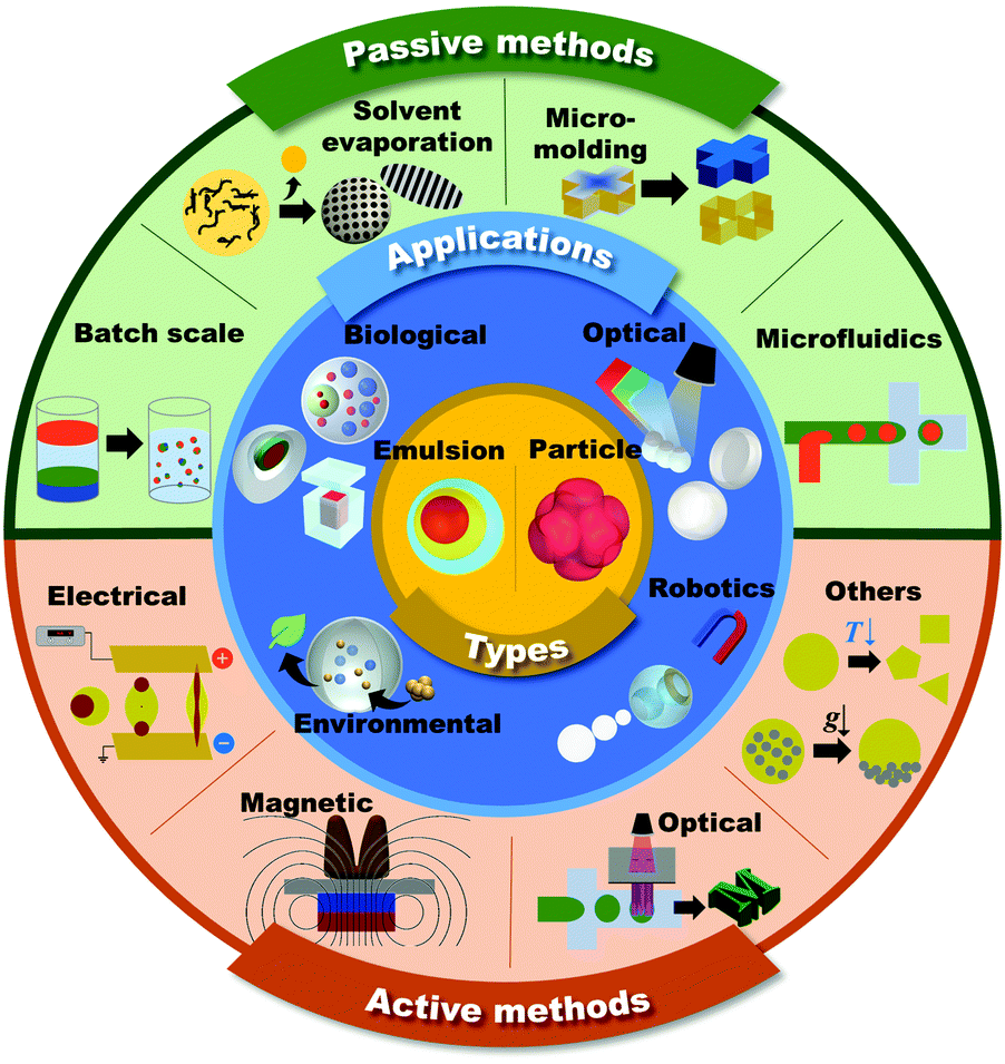 | ||
| Fig. 1 Schematic of the shaping and functionalization of microdroplets and microparticles in passive and active methods, and their applications. | ||
Emulsions are thermodynamically stable dispersions of liquid mixtures consisting of at least two immiscible liquids, such as oil and water.14,15 The emulsions are designated as A/B emulsions, indicating that phase A is covered by phase B (i.e. W/O emulsion means that the aqueous phase (W) is covered with the oil phase (O), and vice versa).16 The complexity of the emulsions increases due to their unique and various geometries such as Janus, Cerberus, or multilayer emulsion forms, and also by their composition, e.g. containing polymers, nanoparticles, biomolecules, or using mixtures of surfactants.6,17–19
Microparticles are solid or gel particles composed of various natural or synthetic substances, such as polymers, lipids, or ceramics.8,20–22 Colloidal nano/microparticles are also used to generate colloidosome microparticles in the form of microcapsules in which colloidal particles are tightly packed as the building blocks for the shell.23–27 The utilization of microdroplets as templates allows the production of versatile microparticles with their shapes largely relying on those of the droplets.28 The precisely controlled emulsion templates are physically or chemically treated for solidification, for example, via gelation or crystallization.29–32 Beyond the materials used, the structure and the shape also determine the properties of the microparticles. With the recent mature development of microfabrication techniques, microparticles are produced in a variety of shapes.
In general, the overall physicochemical properties of the microdroplets are largely governed by both their structures and component materials. Therefore, the consistent and controllable creation of the unique structures of microdroplets is desired in order to meet the ever-increasing demands of microdroplets in various applications.33 This review mainly focuses on introducing the methodologies to generate microdroplets and transforming them into various functional shapes of emulsions or microparticles. The methods are classified into passive and active approaches based on whether additional body forces, such as electrical, magnetic, optical, and mechanical controls, are applied to droplets for their generation or shaping (Fig. 1, outer shell). To explain the explicit principles of each method, we focus more on introducing various morphologies of microdroplets that are manipulated by appropriate methods. The following contents are the latest applications for well-tailored emulsions or microparticles that have been widely applied, especially in the fields of biological, optical, robotics, and environmental applications (Fig. 1, middle shell).
2. Passive methods
Passive methods to manipulate the shaping of the microdroplets rely only on the interfacial forces on the interfaces of the immiscible liquids according to the thermodynamic principles of minimizing interfacial energy. To guide the direction of interfacial forces, well-tailored containers, surfactants or evaporation are used. Here, representative passive methods for manipulating the microdroplet shapes to make emulsions and microparticles using batch emulsification, solvent evaporation and diffusion, micromolding methods, and microfluidic methods are introduced.2.1 Batch emulsification
The typical strategy for fabricating microdroplets on a batch-scale is the simple pipetting or vortexing of immiscible liquids, leading to emulsifying one phase into the other. The resulting topologies of the emulsified microdroplets are shaped based on the free energy balance between the liquids. The batch emulsification provides superiority in the easy and mass production of microdroplets, as compared to other relatively complex manufacturing methods such as microfluidics and micromolding.34–36Various shapes and complexities of the droplets have been designed by manipulating the chemical composition, volume ratio, as well as the number of the mixed solutions.37–39 One-step vortex mixing, the simplest type of emulsification on a batch-scale, was introduced to produce Janus emulsions by Friberg et al. and Guo et al. (Fig. 2A).40,41 The Janus emulsion was made by emulsifying two immiscible oils, a vegetable oil (VO) and a silicone oil (SO), in an aqueous phase (W), so that each droplet consisted of two oils against the minor fraction of aqueous solution.40 The configuration of the emulsions distinctly varied with the weight fraction of the aqueous solution to the total weight of the solution. When a fraction of aqueous solution exceeded 0.3, the simple Janus emulsions of (VO + SO)/W were predominant in the solution, while when the fraction was 0.1, most of the droplets were in forms of double Janus emulsions of (VO + SO)/W/VO, or triple Janus emulsions of (VO + SO)/W/VO/SO. This simple vortex mixing method was further developed to produce finely designed Janus emulsions.42 They quantitatively investigated the effect of the contact angle and the location of the contact plane between the phases on droplet morphology. The contact angle is related to the interfacial tension equilibrium at the contact line between the phases, and the location of the contact plane was determined by the volume ratio of VO/SO within individual droplets. By precisely adjusting the volume ratio of two oils and surfactant concentration, the anisotropic geometry, such as snowman and dumbbell shapes, and the size of Janus droplets could be designed.37–39,41,42
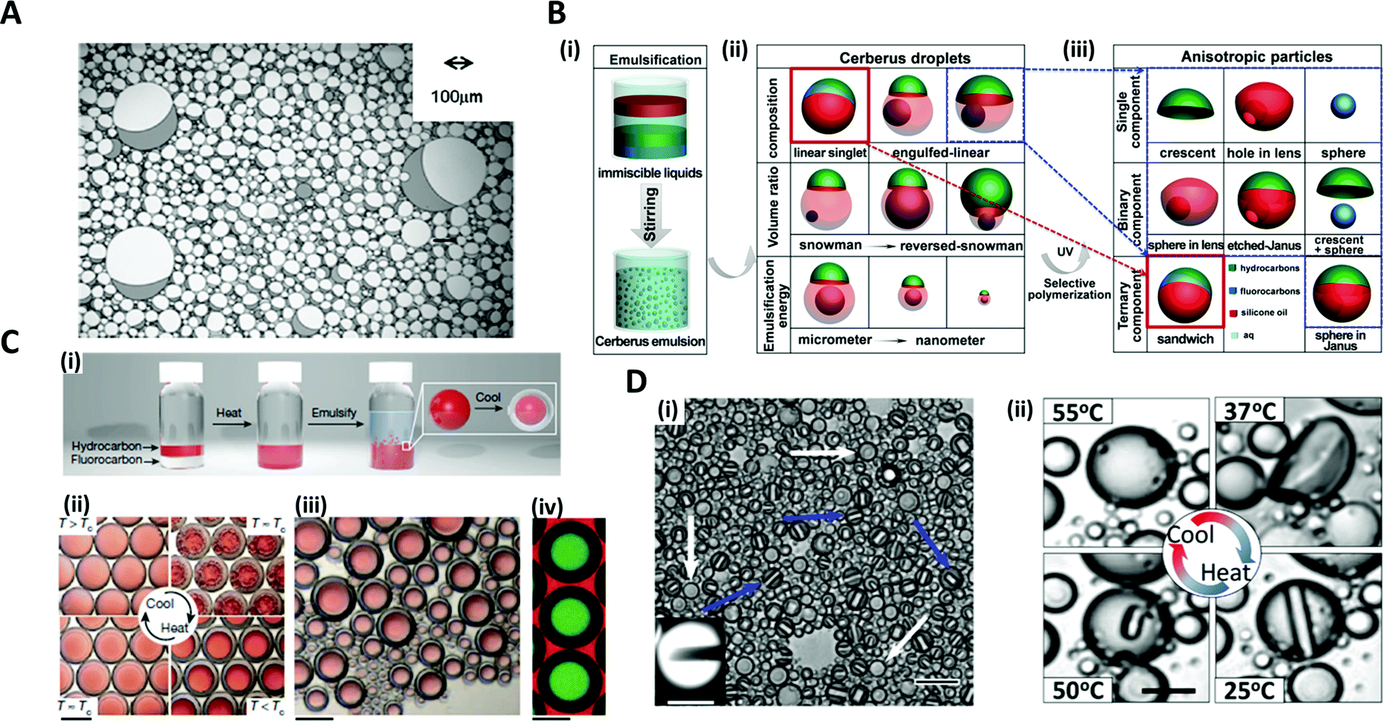 | ||
Fig. 2 Batch emulsification methods for microdroplet generation. (A) Janus emulsions formation from water, vegetable oil, silicon oil and surfactant. (B) Cerberus microdroplet and anisotropic microparticle formation. (i) Emulsification; (ii) various Cerberus droplets obtained by varying the composition, volume ratio, and emulsification energy; (iii) various anisotropic particles templated from the Cerberus droplets. (C) Temperature-controlled phase separation of hydrocarbon and fluorocarbon liquids to create a thermal-sensitive emulsion. (i) Droplet fabrication with a 1![[thin space (1/6-em)]](https://www.rsc.org/images/entities/char_2009.gif) :1 volume ratio of hexane and perfluorohexane in an aqueous solution of nonionic surfactant Zonyl FS-300. (ii) Above Tc, hexane and perfluorohexane are miscible and emulsified. Below Tc, hexane and perfluorohexane phases separate to create a double emulsion droplet; the scale bar is 200 μm. (iii) Droplets produced in bulk by shaking hexane–perfluorohexane liquid show a polydispersed size, while the morphology and composition are uniform; the scale bar is 100 μm. (iv) Lateral confocal cross-section image of double-emulsion droplets; the scale bar is 100 μm. (D) (i) Endoskeletal droplets with the unique disc(C5F12)-in-sphere(C12F26) morphology. Blue arrows and white arrows indicate side-orientated and top-oriented discs, respectively. Inset shows a fluorescence image of a side-oriented disc; the scale bar is 20 μm (10 μm in the inset). (ii) The disc solidified and melted in accordance with temperature; the scale bar is 10 μm. Reproduced with permission from ref. 34, 41, 43 and 44. Copyright 2011 Elsevier. Copyright 2018 American Chemical Society. Copyright 2015 Nature Research. Copyright 2020 American Association for the Advancement of Science. :1 volume ratio of hexane and perfluorohexane in an aqueous solution of nonionic surfactant Zonyl FS-300. (ii) Above Tc, hexane and perfluorohexane are miscible and emulsified. Below Tc, hexane and perfluorohexane phases separate to create a double emulsion droplet; the scale bar is 200 μm. (iii) Droplets produced in bulk by shaking hexane–perfluorohexane liquid show a polydispersed size, while the morphology and composition are uniform; the scale bar is 100 μm. (iv) Lateral confocal cross-section image of double-emulsion droplets; the scale bar is 100 μm. (D) (i) Endoskeletal droplets with the unique disc(C5F12)-in-sphere(C12F26) morphology. Blue arrows and white arrows indicate side-orientated and top-oriented discs, respectively. Inset shows a fluorescence image of a side-oriented disc; the scale bar is 20 μm (10 μm in the inset). (ii) The disc solidified and melted in accordance with temperature; the scale bar is 10 μm. Reproduced with permission from ref. 34, 41, 43 and 44. Copyright 2011 Elsevier. Copyright 2018 American Chemical Society. Copyright 2015 Nature Research. Copyright 2020 American Association for the Advancement of Science. | ||
The Cerberus droplets were produced by mixing three mutually immiscible oils with surfactants in aqueous solution (Fig. 2B(i)). Compared to Janus droplets, the Cerberus droplets provide an additional free dimension, allowing for more complex anisotropic geometries. The Cerberus droplets with various shapes, including linear-singlet and engulfed-linear, were obtained by varying the composition, volume ratio, and emulsification energy (Fig. 2(ii)). By polymerizing a specific component of the Cerberus droplets, anisotropic particles consisting of single, binary, and ternary components were produced with diverse morphologies (Fig. 2B(iii)).34 For instance, by selectively polymerizing the Cerberus droplets consisting of two photocurable oils, i.e. ethoxylated trimethylolpropane triacrylate and methacryl oxypropyl dimethylsiloxane, and incurable fluorocarbon oil, microparticles with crescent moon, sphere-in-lens, and sandwich-Janus morphologies were obtained with homogeneous or multiple distinct chemical compositions.
In order to fine-tune the structure of droplets that were already formed, some researchers programmed the thermodynamic properties of the phases. Swager et al. explored the geometry alternation of the droplets in response to the temperature changes, which induced the phase separation of liquids, providing a simple and scalable approach of compartmentalization.36 When vortexing at a temperature above the consolute temperature (Tc = 22.65 °C), above which phase separation could not occur, hexane and perfluorohexane were miscible and emulsified in an aqueous solution of Zonyl FS-300, which is a nonionic fluorosurfactant (Fig. 2C(i, ii)).43 When cooling below Tc, the phase separation of hexane and perfluorohexane occurred and yielded double-emulsion droplets (Fig. 2C(iii, iv)). A similar phase transformation strategy of fluorocarbon was employed by Borden et al. to reversibly generate the disc-in-sphere geometry of emulsion droplets.44 The perfluoropentane (C5F12)/perfluorododecane (C12F26) liquid mixture was emulsified at a temperature higher than the melting temperature of C5F12. When cooled to room temperature (25 °C), C5F12 was solidified to form solid disc structures, thereby generating endoskeletal droplets with disc-in-sphere structures (Fig. 2D(i, ii)). The disc shape of the inner core arose from the asymmetric growth of crystalline C5F12, where the interfacial transport (removal of latent heat and solute attachment) was faster in the radial direction than in the axial direction.
2.2 Solvent evaporation and diffusion method for the shaping of nano/microparticles
The solvent evaporation method is a versatile and facile technique for producing well-structured nano/micro-scale particles through the self-assembly of block copolymers (BCPs).45–48 A water-immiscible volatile solvent with BCPs is used as the dispersed phase, which is then emulsified with the aqueous phase containing a surfactant in order to form emulsion droplets. The subsequent removal of the solvent by evaporation or diffusion into the aqueous continuous phase converts emulsion droplets into polymeric particles.The self-assembly of BCPs confined in a tiny droplet of hundreds of nanometers generated particles with a periodic structure.49–52 Jeon et al. investigated the interface-driven morphological evolution of a diblock copolymer of polystyrene-block-polybutadiene (PS-b-PB) enclosed in O/W emulsion droplets with polystyrene-block-poly(ethylene oxide) (PS-b-PEO) and poly-butadiene-block-poly(ethylene oxide) (PB-b-PEO) as surfactants.53 The emulsion droplets were solidified by the evaporation of the solvent, yielding PS-b-PB particles with unique external shapes and internal morphologies, which differed depending on the type of surfactant (Fig. 3A). When only PS-b-PEO surfactant was present, onion-like lamellar structured particles were formed, while with the mixed surfactants of PS-b-PEO and PB-b-PEO, prolate particles were formed due to the neutralization of the interfacial affinity for BCPs as well as the surfactant rearrangement at the interface.
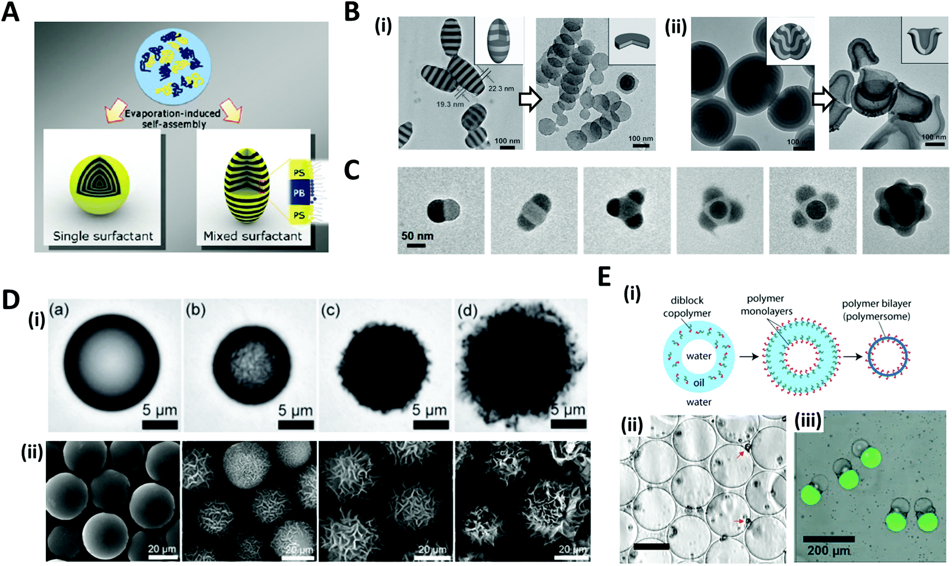 | ||
| Fig. 3 Solvent evaporation and diffusion methods for the shaping of nano/microparticles. (A) Evaporation-induced self-assembly with a single or mixed surfactant. (B) TEM images of (i) ellipsoids with stacked discs and nanodiscs from the ellipsoids after disassembling with ethanol. (ii) Bud-like PDP particles with stacked cup structures and nano-cups from bud-like particles after disassembling. (C) TEM images of PS-b-P4VP colloidal molecules with increasing the number of bulges. (D) (i) Evolution of wrinkled particles from an emulsion droplet containing PS and HD during solvent removal. The elapsed time was (a) 0 s, (b) 49 s, (c) 51 s, and (d) 66 s. (ii) Microparticles obtained from the emulsion droplets containing 10 mg mL−1 PS and varying contents of CA: (a) 0 mg mL−1, (b) 0.5 mg mL−1, (c) 1.0 mg mL−1, and (d) 3.0 mg mL−1. (E) (i) Formation of polymersomes by solvent evaporation from double emulsion templates. (ii) Polymersomes formed from the PEG-b-PLA diblock copolymer. The red arrows indicate aggregates of excess PEG-b-PLA; the scale bar is 50 μm. (iii) Multicompartment PEG-b-PLA polymersomes encapsulating isothiocyanate-dextran (green) and poly-(ethylene glycol) (gray) separately in two compartments. Reproduced with permission from ref. 47, 49, 53, 56, 58 and 60–62. Copyright 2008, 2011, 2012 and 2013 Wiley-VCH. Copyright 2006, 2008 and 2020 American Chemical Society. Copyright 2008 National Academy of Sciences. | ||
Aside from the surfactant effect, the addition of polymer-coated surfactant nanoparticles also leads to dramatic changes in the shape of the particles.51,52 The nanoparticles modulate the interfacial interactions between the emulsion droplets containing BCPs and the surrounding amphiphilic surfactant. Meanwhile, by the selective crosslinking of the dispersed phase of self-assembled BCPs and the subsequent disintegration of the uncrosslinked phase, the complex structured particles, e.g. cylinders, Janus, ring, and disc structures, were fabricated from the pre-formed BCP assemblies.49,54,55 Deng et al. produced polystyrene-b-poly(4-vinyl pyridine) (PS-b-P4VP) particles that were hydrogen-bonded with 3-n-pentadecylphenol (PDP), as the pre-formed BCP assemblies (Fig. 3B).49 Subsequent disassembly of the BCP particles by breaking the hydrogen bond disintegrated the particles to produce individual components. The amount of PDP greatly influenced the structural change. When PDP was not included, a symmetrical copolymer of PS-b-P4VP was formed, which had ellipsoids with a stacked lamellar structure (Fig. 3B(i)). By disassembling the stacked PS-b-P4VP lamellar ellipsoids in ethanol, which is a good solvent for P4VP but not for PS blocks, nano-disc particles were obtained. The introduction of PDP into PS-b-P4VP induced the internal morphological transition to bud-like particles with stacking cup structures, and disassembling the stacked cups derived isolated particles with individual nano-cups (Fig. 3B(ii)). When PS-b-P4VP was self-assembled under strong confinement conditions, typically, where the particle size was less than 100 nm, colloidal molecules with various bulging 3D structures, e.g., snowmen, dumbbells, triangles, tetrahedral, and raspberries, were synthesized (Fig. 3C).56,57 Bulges regularly protruded from the particle surface and the number of bulges increased depending on the particle size.
When the size of the emulsion droplet was increased to the microscale, polymer microparticles with controllable surface textures were produced by the interfacial instabilities of emulsion droplets.47,58 Emulsion droplets of solvent containing hydrophobic polymers or BCPs, such as polystyrene (PS) or PS-b-poly(methyl methacrylate), and fatty alcohol co-surfactants such as n-hexadecanol (HD) and n-cetyl alcohol (CA), were generated. The continuous phase was an aqueous solution with surfactant. As the organic solvent diffused and evaporated through the aqueous phase, a reduction in the interfacial area of shrinking emulsion droplets triggered interfacial instabilities to form wrinkled surfaces (Fig. 3D(i)). The surface textures of the particles could be precisely adjusted from smooth to rough textures by varying the surfactant concentration or the rate of solvent evaporation. For example, as the contents of CA increased from 0.1 to 3 mg mL−1, the surface roughness of the particles gradually increased from slight to enhanced wrinkles (Fig. 3D(ii)).
The solvent evaporation method was also utilized to fabricate polymersomes which are vesicles surrounded by membrane walls composed of lamellae of BCPs.59 A double emulsion, W/O/W droplets with a core–shell structure, was typically prepared with BCPs dissolved in the middle oil phase.22,60,61 Evaporation of the solvent oil then led to the assembly of BCPs into monolayers at the oil–water interfaces, accordingly forming the polymer bilayers, polymersomes (Fig. 3E(i, ii)).60,61 By preparing the double emulsions with different numbers of inner aqueous droplets for the templates, non-spherical polymersomes could be produced, which encapsulated multiple compartments (Fig. 3E(iii)).62
2.3 Micromolding methods for structured microparticle generation
In the conventional micromolding technique, a curable fluid is filled into shaped micromolds and it becomes solid particles with replicated shape via polymerization, thereby creating the specific three-dimensional microstructures in a simple, scalable, precise and controllable manner.63–65 DeSimone et al. pioneered a technique, known as particle replication in a nonwetting template (PRINT), to produce monodisperse particles while simultaneously controlling the structure and function of the particles.66–68 They fabricated a perfluoropolyether (PFPE) mold with negative micro/nano features to imprint it on a liquid precursor compound. This mold was not wet with organic material, allowing liquid precursor entrapped within the mold features to be isolated and solidified into the target shape (Fig. 4A). The PRINT technology has evolved into an automated roll-to-roll system for the continuous and mass production of the particles.69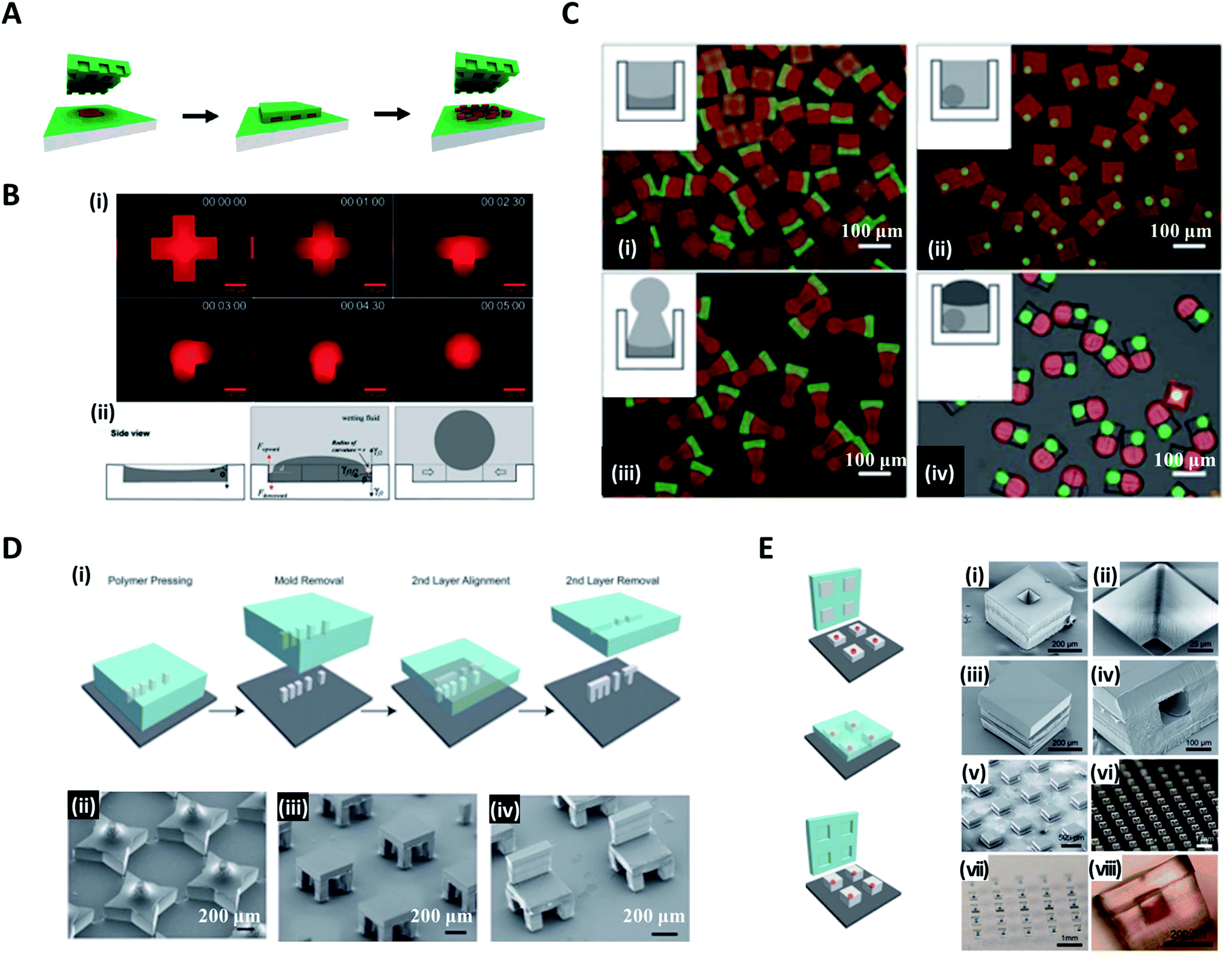 | ||
| Fig. 4 Micromolding methods for structured microparticle generation. (A) In the PRINT process, the mold composed of the nonwetting fluorinated materials and surfaces confines the liquid precursor inside the features, which could generate isolated particles. (B) Distinct shapes of microparticles in an identical micromold. (i) Evolution from liquid solution to spherical droplet. (ii) Sequential steps of loading photocurable fluid, wetting, and droplet formation for droplet formation in the micromold. (C) Controlled fabrication of microparticles with complex 3D geometries of (i) concave-flat, (ii) microspheres enclosed in cuboid, (iii) concave-sphere/nonsphere, and (iv) tricompartment particles. (D) Assembly of 3D microstructures using the (i) stamped assembly of polymer layers (SEAL) process. A variety of microstructures made by the SEAL method, including (ii) stars, (iii) two-layered tables, and (iv) three-layered chairs. (E) SEAL-fabricated controlled-release microparticles by aligning an array of particle caps with drug-filled bases. SEM images of (i) a single particle, (ii) the core of a particle, (iii) a sealed particle, (iv) a cross-section of a single particle and (v) an array of sealed particles. Optical images of (vi) an array of bases, (vii) an array of filled particles, and (viii) a side view of a single-filled particle. Reproduced with permission from ref. 66, 71, 72 and 74. Copyright 2005 and 2015 American Chemical Society. Copyright 2012 Wiley-VCH. Copyright 2005 American Association for the Advancement of Science. | ||
In contrast to the studies in which particles formed replicated shapes of the mold, Choi et al. attempted to synthesize various shapes of particles with spherical, convex, concave, and Janus forms, which differed from the original shapes of the molds by utilizing surface-tension-induced flow.65,70,71 Poly(dimethylsiloxane) (PDMS)-based micromolds fabricated from standard soft lithography were filled with photocurable poly(ethyleneglycol)-diacrylate (PEG-DA) solution. Once the wetting fluid (mineral oil) containing a photoinitiator was applied on top, the curvature of the PEG-DA solution was formed due to the interfacial tension between the wetting fluid and the photocurable fluid; thereafter, the photocurable solution polymerized to a uniform 3D curvature (i.e. concave or convex) and monodisperse spheres (Fig. 4B(i)).72 The curvature of the wetting fluid formed on the edge of the mold induced the pressure difference to cause the photocurable fluid to move toward the center of the mold and consequently formed a spherical droplet (Fig. 4B(ii)). With a similar strategy, Jung et al. demonstrated the fabrication of chemically functional and monodisperse hydrogel microspheres with a macroporous core–shell structure.73 Highly uniform poly(ethyleneglycol)-based microspheres containing an aminopolysaccharide chitosan were fabricated utilizing surface-tension-induced droplet formation followed by polymerization-induced phase separation.
Choi et al. further reported the controlled fabrication of complex 3D shapes of microparticles based on the swelling of the mold and the capillarity between various wetting fluids (fluorinated oil, paraffin oil, PDMS 20 cP, and PDMS 5 cP) and the photocurable solution.71 When the PDMS-based mold was exposed to the wetting fluid, the mold swelled and this led to the spatial deformation of the inner photocurable solution. The solution was transformed into its final shape by the capillary force between the solution and wetting fluid and then solidified via ultraviolet (UV)-induced polymerization, whereby polymer particles with permanent structures were obtained.2,71 Multi-compartment microparticles with nonsphere/nonsphere and sphere/nonsphere configurations were fabricated by sequentially combining the above manufacturing processes. Fig. 4C(i)–(iv) show the concave-flat, microspheres enclosed in cuboid, concave-sphere/nonsphere, and tri-compartment microparticles (possessing spherical, concave, and convex shapes within a single particle), respectively.
On the other hand, microparticles with higher-order complex geometry could be produced by the layer-by-layer combination of the imprinted particles, named the stamped assembly of polymer layers (SEAL) method. McHugh et al. produced high-resolution microparticles by SEAL with a variety of materials, including biodegradable poly(lactic-co-glycolic acid) (PLGA).21,74 PDMS was used as an inverse elastomeric mold derived from a silicon wafer mold with complementary patterns etched by the microfabrication technique (Fig. 4D(i)). The PLGA was heated and pressed into the PDMS molds to produce the micro-components of interest, and then delaminated onto a separate surface such as a glass substrate. Subsequent layers for the final structure were assembled with micro-alignment through a layer-by-layer sintering process. In this way, SEAL facilitated the formation of large arrays of microstructures, including a 3D star, a two-layered table, and a three-layered chair (Fig. 4D(ii, iii and iv)). The core–shell particles embedding the drug solution were also created by using the same SEAL strategy. The thermoplastic polymer containers were fabricated from the mold, filled with drug, and then sealed with polymer lids (Fig. 4E).
2.4 Microfluidic methods for complex structured microdroplet formation
Microfluidic systems offer a versatile route to produce highly monodisperse emulsions with unprecedented accuracy.75,76 Microfluidic droplet generator devices manipulate the discrete and small volumes (micro to femto liter) of immiscible fluids in a laminar flow regime. For generating microdroplets, an inner fluid, called the dispersed phase, is introduced into another immiscible fluid, named the continuous phase, thereby leading to a breakup of the inner dispersed phase into monodisperse droplets. The dripping of the inner fluid is a resultant of competing stresses between surface tension, which reduces the interfacial area, and viscous drag force, which drags the interface segment.77The glass capillary microfluidic device, which has been widely used, was first introduced by Weitz et al. in 2007.78 Glass exhibits high strength and rigidity, high chemical stability, and transparency that facilitates internal flow.79 The glass capillaries are heated and pulled into a fine tip, and aligned to a fluid path. In a coaxial flow device, a round capillary is aligned into a square one in which the continuous and dispersed phases flow in the same direction.76 As the fluids flow, monodisperse droplets are periodically formed at the tip of the capillary orifice. In an alternate geometry of a flow-focusing device, the continuous and dispersed phases are introduced from the opposite side of the capillaries. The inner fluid is hydrodynamically focused by the outer fluid and ruptured into tiny droplets at the narrow-tapered orifice. The co-flow and flow-focusing geometries can be combined and repeated in a manner for producing multiple emulsions (Fig. 5A).75,76,80
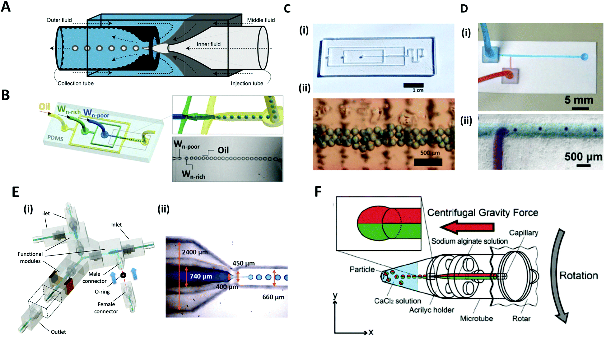 | ||
| Fig. 5 Microfluidic methods for the formation of microdroplets with complex structures. (A) A schematic illustration of a microcapillary device that combines co-flow and flow-focusing to create double emulsions. (B) PDMS-based microfluidic device to generate double emulsions. (C) (i) Acrylic-based microfluidic droplet generator. (ii) Consecutive droplets within the generator. (D) (i) T-shaped open-channel paper microfluidic device. (ii) Generation of droplets in paper microchannels. (E) 3D printed modular microfluidic system. (i) Assembly of microfluidic modules. (ii) 3D printed co-flow droplet generator and droplet generation process. (F) Centrifuge-based droplet formation from multi-barrelled capillaries. Sodium alginate solutions pumped out from the capillary form pendant droplets and detach when the centrifugal force surpasses the interfacial force applied by the capillary orifice. Reproduced with permission from ref. 78, 81 and 83–86. Copyright 2007 Materials Research Society. Copyright 2012 and 2020 Wiley-VCH. Copyright 2018 Nature Research. Copyright 2013 Royal Society of Chemistry. Copyright 2019 Springer. | ||
PDMS-based microfluidic devices mostly have the planar flow-focusing configuration mounted on a glass substrate (Fig. 5B).81 PDMS is by far the most widely used material for the microfluidic devices due to its advantages of transparency, flexibility, biocompatibility, and ease of mass-production.82 In addition, lithography techniques (soft-lithography and photo-lithography) allow for the fabrication of highly complex flow channels with high resolution down to ∼1 μm, allowing multi-functions to be realized in the microdevice. Despite these advantages, the lithographic technique still requires specialized equipment, expensive base materials, and considerable expertise.83 As an alternate low-cost and simple method, for instance, acrylic-based microfluidics or paper-based microfluidics have been introduced (Fig. 5C and D).83,84 In this sense, Song et al. recently introduced a 3D printed modular microfluidic system for droplet generation (Fig. 5E).85 The microfluidic designs were printed directly with a transparent UV-curable polymer by a high-precision 3D printer. Once properly cured, the modules were assembled with their unique connector design in a leak-free manner with minimal hydraulic resistance (Fig. 5E(i)). Since each individual module can be designed and assembled for a specific purpose, this modular system has a high degree of flexibility for broader applications. They demonstrated that these integrated modules could produce and manipulate emulsion droplets ranging from single-phase to dual-core multiphase droplets (Fig. 5E(ii)).
Unlike the above examples in which additional flow-inducing pumps are required, Maeda et al. introduced a centrifuge-based droplet shooting device (Fig. 5F).86 A typical tabletop centrifuge and a microtube, where a multi-barrelled capillary channel was built-in, were needed for particle synthesis. During centrifugation, the solution filled in each capillary barrel was pumped out due to centrifugal force, and formed pendant droplets at the tip of the capillary. The droplets detached from the orifice when centrifugal force surpassed the counteracting drawing force of interfacial tension.
2.5 Complex structured microdroplets and microparticles formed by microfluidics
Versatile designs of microfluidic devices enable the production of microdroplets with highly diverse structures where the number, content, volume ratio and size of the encapsulated droplets can be controlled.76,80,86–88 Wang et al. constructed a microfluidic device by the on-demand arrangement of three basic building blocks: (i) a droplet maker for generating droplets, (ii) a connector for merging droplets from different droplet makers, and (iii) a liquid extractor for removing redundant fluid from the continuous phase.87 This hierarchical microfluidic device enabled the generation of various high-order multicomponent multiple emulsions, such as quadruple-component double emulsions, quintuple-component double emulsions, quintuple-component triple emulsions, and even sextuple-component triple emulsions (Fig. 6A). Similarly, by using a multi-barreled capillary for inner core fluid, particles possessing axisymmetric three-, four-, and six-compartment bodies were obtained (Fig. 6B).86 The pendant droplets from each capillary, which contained sodium alginate solutions, were immediately gelated in a CaCl2 solution reservoir so that the multi-compartment particles retained axially symmetric geometries with clear compartmental separations. Meanwhile, the hollow microcapsules with two different sides (Janus shells) could also be formed from the double emulsion templates (Fig. 6C).89 Two co-flowing poly(N-isopropylacrylamide) (pNIPAm) photocurable streams, each of a different color, were used to encase the kerosene oil droplet and were emulsified with paraffin oil (Fig. 6C(i)). The curing of the pNIPAm droplets with UV polymerization and the removal of the inner kerosene oil phase by washing with isopropanol yielded the hollow microcapsules with two distinguishable halves (Fig. 6C(ii, iii)).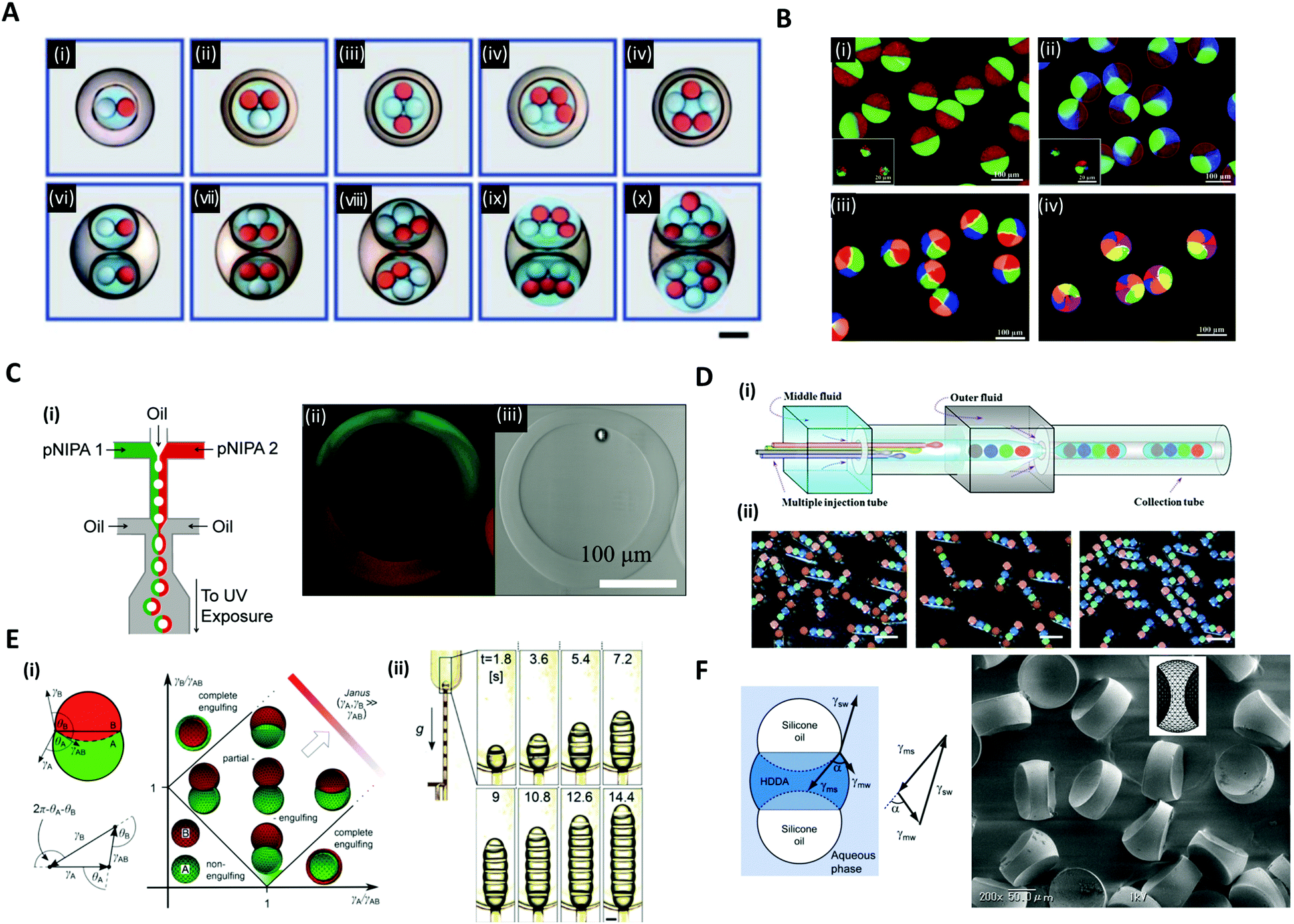 | ||
| Fig. 6 Complex structures of microdroplets and microparticles formed by microfluidic methods. (A) Optical micrographs of quintuple-component triple emulsions that contain two different kinds of droplets in the innermost level; the scale bar is 200 μm. (B) Particles possessing a multi-compartment with axisymmetric geometries. (i) Janus particles, (ii) three-compartment particles, (iii) four-compartment particles, and (iv) six-compartment particles. (C) (i) Microfluidic formation of a hollow Janus shell. The inner oil was removed by washing after UV polymerization. (ii) Fluorescence and (iii) bright-field micrographs of the hollow Janus shell. (D) (i) Generation of double emulsions with the rod-like barcodes. (ii) Polymerized barcodes with position-indexed photonic crystal cores; the scale bars are 200 μm. (E) (i) Double droplet with contact angles θA and θB and the Neumann's triangle. Stability diagram representing possible morphologies of a double droplet consisting of phases A and B, where VA = VB. (ii) The formation of multiple droplets with increasing segments with time; the scale bar is 200 μm. (F) The balance of three interfacial tensions of a ternary droplet emulsion. Biconcave microparticles fabricated using selective photopolymerization. Reproduced with permission from ref. 17, 30, 32, 86, 87 and 89. Copyright 2010, 2011 and 2012 Royal Society of Chemistry. Copyright 2012 and 2014 Wiley-VCH. Copyright 2012 Nature Research. | ||
In addition to the aforementioned spherical droplets, it is also possible to create non-spherical droplets with microfluidics. Zhao et al. employed a capillary microfluidic device composed of four inner capillaries, one middle and one outer capillary for the generation of elongated rod-like double emulsion templates consisting of multiple colloidal photonic crystal- or magnetic-labeled ETPTA cores and a PEG hydrogel shell (Fig. 6D(i)).30 The four-core double emulsion template was compressed by the outer capillary to form an elongated shape arrayed with four photonic crystal cores, followed by UV polymerization (Fig. 6D(ii)). Because the photonic crystal cores possessed distinct and extremely stable reflection wavelengths, the polymerized microparticles were applied as a barcode system. The non-spherical droplets were also generated by using the Janus droplet templates where the interfacial forces of the three liquid phases were precisely controlled.17,32 Guzowski et al. examined the microdroplets made up of multiple Janus droplets, i.e., an arbitrarily long chain of immiscible droplet segments (Fig. 6E).17 When droplets of two immiscible liquids were brought into contact with a third host liquid, three equilibrium topologies appeared, depending on the interfacial tensions between the three liquid phases, i.e., non-engulfing, complete engulfing, and partial engulfing configurations (Fig. 6E(i)). The multiple Janus droplets could be generated by supplying partially engulfed two-liquid phases one after the other, carefully preventing the coalescence of the segments (Fig. 6E(ii)). In these droplet chains, the individual segments were bound by three interfaces: one with the external phase and two with the adjacent segments of the other phase. Accordingly, the segments formed interchangeable biconvex and biconcave particles. The synthesized biconvex and biconcave particles of less than 100 μm in diameter could be used as optical microlenses. Nisisako et al. also showed the fabrication of biconcave polymer microlenses from ternary emulsion droplets (Fig. 6F).32 Monodisperse ternary emulsion droplets were produced, which contained a photocurable phase of a 1,6-hexanediol diacrylate (HDDA) and two non-curable segments of SO. In the ternary droplet templates (SO-HDDA-SO of the three-phase parallel stream), only the photocurable HDDA phase was selectively polymerized and SO phases were removed, whereby polymeric microparticles with two concave surfaces were formed. The radius of curvature of the lenses could be varied by controlling the flow rate ratios of the three phases within a microfluidic droplet generation device.
3. Active methods
Active methods utilize external energy input such as electric, magnetic, optic, and mechanical controls to modulate the microdroplet shape. The additional energy input modifies the force balance at the interface and thus manipulates interfacial instabilities.3.1 Electrical method for manipulating microdroplets
When an electric field of strength E0 is applied to the liquid droplet submerged in another low-conductive immiscible liquid, free charge in both liquid phases accumulates at the interface between the two immiscible fluids, inducing electrical stress and electro-hydrodynamic flow around the droplet. The electrical stress causes the electro-hydrodynamic deformation of the droplet, which was theoretically explained by Taylor with a ‘leaky dielectric model’.90 This model scales the electrical stress under a DC electric field applied to the droplet as fE ∼ Ω(R,S)CaE, where R = σin/σout and S = εin/εout represent electrical conductivity (σ) and the permittivity (ε) ratio of the droplet (in) and the outside liquid (out), respectively. The electric capillary number (CaE = εoutE02a/γ) is the ratio of electric force to interfacial force, where a is the droplet radius and γ is the interfacial tension. The droplet deformation type is classified according to the ratio of R and S. For instance, a castor oil (CO)/silicone oil (SO) droplet is deformed into the prolate (PR) shape when R/S > 1, and into the oblate (OB) shape when (R/S < 1) (Fig. 7A).91–93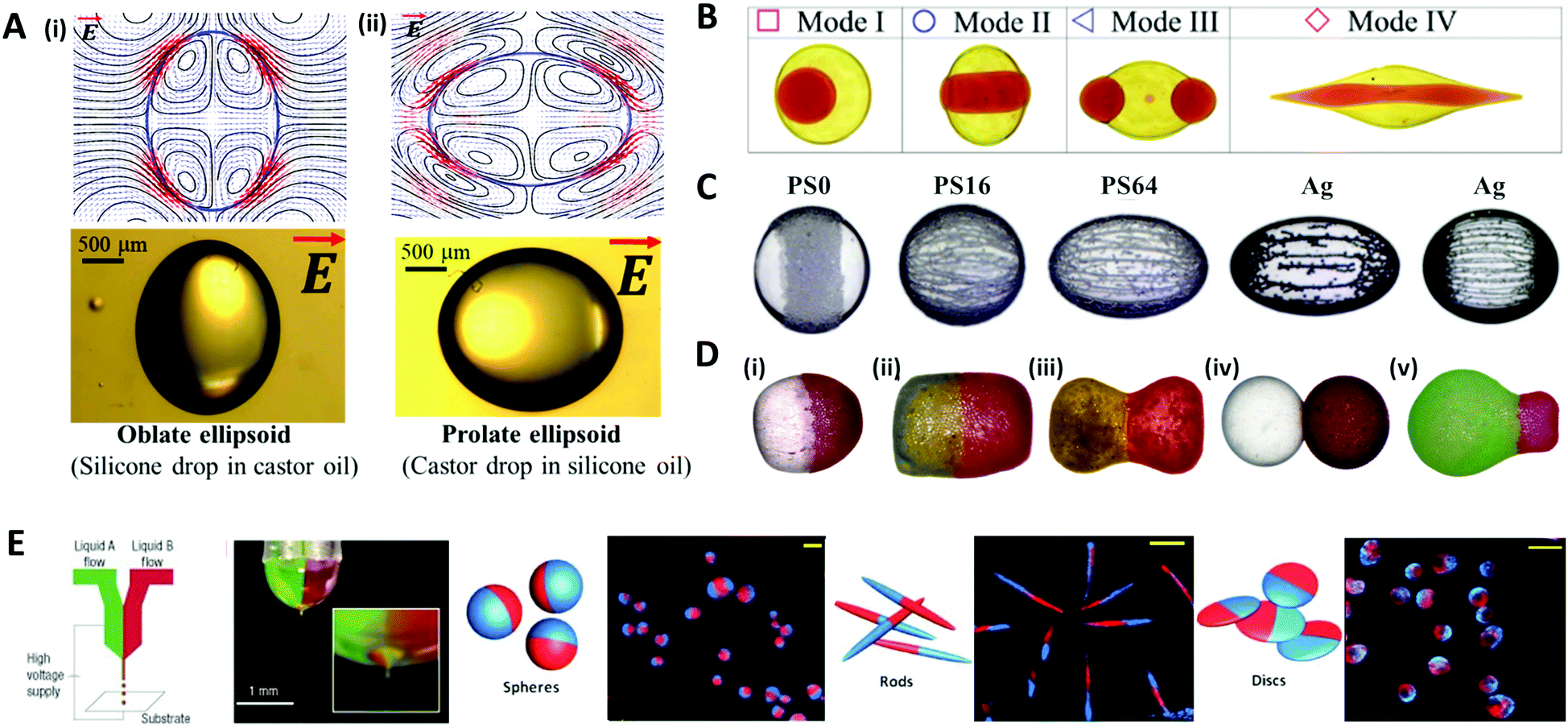 | ||
| Fig. 7 Electrical methods for manipulating microdroplets. (A) Simulation and experimental results of the electro-hydrodynamic deformation of emulsion droplets. The stream lines and the shapes of (i) the oblate deformed droplet (R/S < 1) and (ii) the prolate deformed droplet (R/S > 1). (B) Multimodal breakup of CO/SO/CO double emulsion droplets under a DC electric field. (C) Electric field-induced assembly of polystyrene (PS) particles (40 μm) and silver-coated glass spheres (15 and 55 μm) on a silicone oil droplet. The PS particles were chemically treated to increase their electrical conductivity and labelled as PS0, PS16, and PS64, where the numbers refer to the sulfonation reaction time in minutes. (D) Various types of Janus capsules fabricated by the electro-coalescence of patchy colloidal oil droplets with different particle concentrations and droplet sizes: (i) spherical capsule, (ii) oval capsule, (iii) dumbbell-like capsule, (iv) double-ball capsule, and (v) bulb-like capsule. (E) The electro-hydrodynamic co-jetting process for generating bicompartmental spherical, rod-shaped, and discoid microparticles; the scale bars are 10 μm. Reproduced with permission from ref. 92, 101, 106, 115, 118 and 119. Copyright 2020 Multidisciplinary Digital Publishing Institute. Copyright 2018 and 2019 Royal Society of Chemistry. Copyright 2016 Springer. Copyright 2010 Wiley-VCH. Copyright 2005 Nature Research. | ||
The deformation of a multi-phase emulsion droplet could be described in the same way as that of a single emulsion droplet. For example, under a weak electric field, the spherical double emulsion droplet is deformed into PR–PR, PR–OB, OB–PR, and OB–OB (inner–outer interface; PR stands for prolate and OB stands for oblate) according to the R/S across each interface.94–97 When the electric field strength increases, the emulsion droplet becomes unstable and eventually breaks up, which has been studied for various applications.98–100 Abbasi et al. reported the various breakup modes of double emulsion droplets, CO/SO/CO and W/SO/CO, under a DC electric field (Fig. 7B).101,102 In this system, the volume ratio of the core and shell (β), electric capillary number (CaE), and interfacial tension (γ) decided the breakup modes of the core droplet, and depending on the mode, the broken double emulsion droplet turned into an asymmetric Janus droplet or ternary droplet when removing the electric field. They plotted these results and their theoretical criteria for changing from mode I to II in a β vs. CaE parametric space.
Particle-covered droplets, called a colloidosome or Pickering emulsion, are one of the typical templates for making functional particles. Initially, Singh and Auory used an AC electric field to bind or remove particles from the droplet interface.103,104 Dommersnes et al. reported that particles anchored at the interface were structured in the form of a belt (non-conductive particles) or chain (conductive particles) under the DC electric field.105 This work was extended to study the effect of electric conductivity, size, and coverage of particles on the degree of deformation and shape of droplets (Fig. 7C).106 A SO/CO droplet without particles, and a droplet covered with particles in low coverage (∼0.1 area fraction) were similarly deformed into an oblate shape. On the other hand, at high particle coverage (over 0.4 area fraction), the droplet was deformed in an oblate shape (non-conductive particle) or a prolate shape (conductive particle), as the particles had more influence on the droplet deformation.92,107–109
Under an electric field, two droplets attract each other by electrostatic forces and subsequently merge into one droplet, which is commonly referred to as electro-coalescence.110–112 Rozynek et al. coalesced the Pickering droplets via an electric field to produce well-tailored Janus and patchy capsules (Fig. 7D).113–115 When applying the DC electric field to the two droplets covered with particles, the non-conductive particles were actively structured in a belt shape on the droplet interface. Then two droplets with belt-like structures attracted each other and coalesced to form a densely packed Janus droplet. In the same manner, an asymmetric Janus capsule was made by adjusting the size of each droplet and particle concentration, and a multi-patchy capsule was produced by repeating electro-coalescence.
Other methods of producing functional droplets or particles using an electric field include electro-spraying or jetting, which are electro-hydrodynamic atomization methods where micro/nano-size droplets are massively produced by electrical stress at the tip of the nozzle. For the production of multifunctional particles or the material encapsulation, a co-axial electro-jetting method has been reported, which supply multiple compartments with one nozzle.116,117 The effect of the concentration and flow rate of the polymer solution on the morphology of biphasic particles during the electro-hydrodynamic co-jetting process was investigated (Fig. 7E).118,119 Disc-shaped particles were generated from low concentration solutions (up to 3.4 wt% of poly(lactide-co-glycolide) solution), whereas the spherical particles were produced from higher concentration solutions. The rod-shaped particles were made only under specific conditions with a solution concentration of 3.4 wt% and a flow rate of ∼0.45 mL h−1.
3.2 Magnetic method for manipulating microdroplets
A magnetic force acts locally on the magnetic reactive materials, and this force can be applied to various applications, such as in drug delivery,120 micro-swimmers,121 and oil/water separation,122 where particles or structures have to be individually manipulated. A ferrofluid, widely used as a material for magnetic droplets, is a stable colloidal suspension composed of ferro- or ferrimagnetic nanoparticles (such as iron oxide nanoparticles) that are dispersed in a carrier liquid (organic solvent or water).123 This liquid exhibits a reversible shape change as it is magnetized and demagnetized with or without a magnetic field. When a uniform magnetic field (H) is applied to a spherical ferrofluid droplet suspended in a non-magnetizable immiscible fluid, the droplet is elongated in the direction of the field (prolate shape) (Fig. 8A).124–126 This phenomenon is equivalent to the aforementioned deformation of the conductive droplet suspended in a low-conductive liquid by the electric field. Landau and Lifshitz derived an analytical model for the aspect ratio of deformed droplets under a low magnetic field as a function of magnetic bond number (Bom = μoutH2a/γ, where H and μ are the magnetic field strength and magnetic permeability, respectively), which indicates the ratio of the magnetic force to the interfacial force between the droplet and the carrier liquid.127 Afkhami et al. revealed that the aspect ratio of the droplet gradually increased with Bom, corresponding to the analytical model at low magnetic field, while the deformation of the droplet deviated at high magnetic field as the interfacial tension varied with the magnetic force.124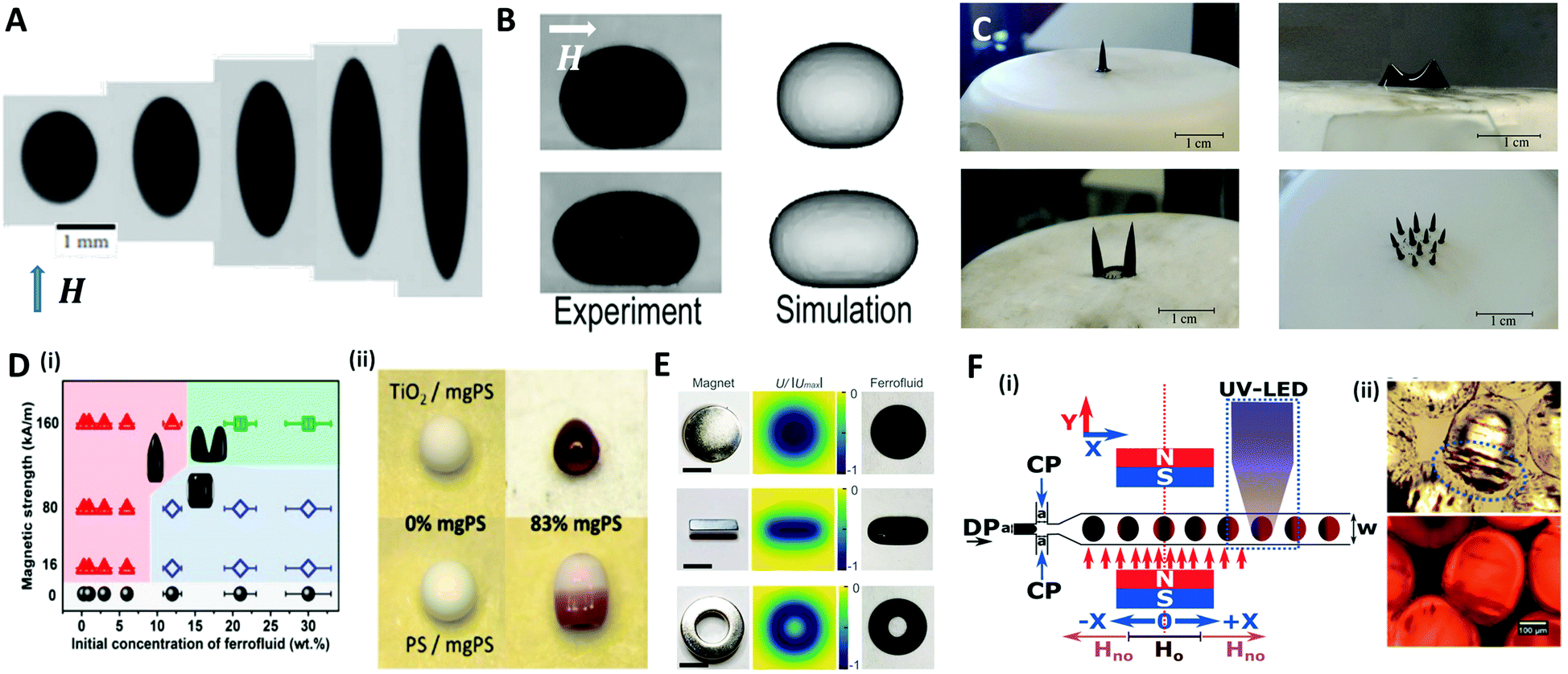 | ||
| Fig. 8 Magnetic method for manipulating microdroplets. (A) Elongated PDMS ferrofluid droplet emerging in glycerol solution under various magnetic field strengths (H = 6.0, 12.2, 23.9, 59.8, 162.3 kA m−1 (from left to right)). (B) Experimental and numerical results of the deformation of a sessile ferrofluid droplet under the different magnetic field strengths (Bom = 57 for top and 807 for bottom). (C) Magnetically triggered ferrofluid droplet deformation and division on a superhydrophobic surface when the magnetic field intensity increases. (D) (i) Structure map of the supraparticles with various shapes obtained by the evaporation-guided assembly of magnetic nanoparticles. (ii) Binary supraparticles fabricated by drying a co-suspension under magnetic field. (E) Complex shapes of ferrofluid droplet produced by permanent magnets in disk-, cube-, and ring-shapes; the scale bar is 10 mm. (F) (i) Synthesis of magnetic Janus particles within a flow focusing droplet generation system with magnetic field and UV LED. (ii) Optical images of generated magnetic Janus particles. The blue ellipse indicates the accumulated magnetic components. Reproduced with permission from ref. 124, 128, 131–133 and 138. Copyright 2010 and 2018 Cambridge University press. Copyright 2011 and 2017 Royal Society of Chemistry. Copyright 2019 American Chemical Society. Copyright 2010 National Academy of Sciences. | ||
Zhu et al. studied the deformation of an aqueous sessile ferrofluid droplet on a hydrophobic substrate by a uniform magnetic field applied in a direction parallel to the substrate surface (Fig. 8B).128 A comparison of experimental and numerical results showed that the non-linear elongation of the ferrofluid droplet in the direction of the field occurred due to the non-linear magnetization of the ferrofluid known as Langevin's magnetization law.129 On the other hand, Timonen et al. applied a vertical magnetic field to a superhydrophobic surface on which a ferrofluid sessile droplet was placed, and observed the deformation of the droplet into a spiked cone shape due to the magnetic field gradient in the vertical direction (dH/dz) acting on the droplet.130 Vieu et al. expressed this phenomenon in a theoretical manner.131 When the magnetic field strength was further increased, the ferrofluid droplet split into two smaller droplets at the critical field strength (Fig. 8C). However, the deformation of ferrofluid droplets induced by the magnetic field could not retain their shape when the field was withdrawn because of the nanoparticles' superparamagnetism. To fabricate the supraparticles with permanent unique shapes, Hu et al. proposed a method of irreversibly deforming aqueous ferrofluid droplets using an evaporation-guided colloidal assembly with an external magnetic field.132 They observed the differently shaped particles by controlling the magnetic field strength and the concentration of Fe3O4/polystyrene (mgPS) nanoparticles in the ferrofluid as depicted in Fig. 8D(i). Binary supraparticles were produced by drying a co-suspension of mgPS nanoparticles with titanium dioxide or polystyrene nanoparticles (Fig. 8D(ii)).
To diversify the structure of the droplets into more complex morphologies, Fan et al. tuned the magnetic field distribution via the shape or arrangement of permanent- or electro-magnets (Fig. 8E).133 This technique enabled the simultaneous control of the morphology and the spatiotemporal position of the ferrofluid droplet as a miniature soft robot for liquid cargo, channel valves, and so on.
In a microfluidic system, the ferrofluid is used as a dispersed phase to produce droplets whose size or morphology is precisely manipulated. The direction of the magnetic field determined by the position of the magnet is an important parameter to control the size and frequency of the generated droplet.134–136 For example, a magnet placed upstream of a T-shaped droplet generator delayed the breakup and increased the size of the droplet by pulling the ferrofluid. Conversely, a magnet downstream accelerated the breakup and reduced the size of the droplet.137 Varma et al. applied the magnetic field after droplet generation to fabricate a magnetic Janus droplet (MJD).138 When the Fe3O4 nanoparticles-laden droplet passed the magnetic field perpendicular to the flow direction, the magnetic nanoparticles were concentrated at the rear part of the droplet to form the MJD, followed by the UV polymerization for particle synthesis (Fig. 8F).
3.3 An optical method for fabricating complex-shaped microparticles
The aforementioned methods for the formation of microparticles using droplets as their template limit the shape of the particles to spherical shapes due to the interfacial tension, which instigates the droplet to maintain their spherical shape. To overcome this limitation, Dendukrui et al. introduced a one-step particle synthesis method called continuous-flow lithography (CFL) by combining the microscope projection photolithography with PDMS-based microfluidic devices.139 In CFL, a single-phase photocurable oligomer stream was exposed to a UV light pulse to produce functional particles with mask-defined shapes, such as triangular, rectangular, or hexagonal shapes with sharp edges. In the UV light, the non-polymerized lubricating layer of oligomers resulting from oxygen-aided inhibition near the PDMS walls allowed for polymerized particles to be flushed out by the stream. This method was improved to produce amphiphilic, nonspherical Janus particles by co-flowing immiscible photo-polymeric fluids in microfluidic devices.140,141Fig. 9A demonstrates the synthesis of amphiphilic Janus microparticles using CFL-based polymerization. The mask-defined wedge-shaped particles were formed across two parallel laminar, co-flowing streams containing a hydrophilic oligomer (PEG-DA) and a hydrophobic oligomer (TMPTA).140 Chung et al. purposed an optofluidic maskless lithography technique by replacing the photomask used in CFL with the programmable two-dimensional spatial light modulators.142 However, the use of high flow rates in the CFL limits the throughput of the sufficiently polymerized particles because the particles are smeared due to the finite pulses of UV light. To overcome this problem, Dendukuri et al. proposed a technique named stop-flow lithography (SFL), in which the oligomer was exposed to light pulses only when it was stationary.143 The process of SFL consisted of three states as shown in Fig. 9B: (i) The flow was stopped by closing the valve; (ii) the array of particles was polymerized from the stationery monomer film by opening the shutter; (iii) polymerized particles were flushed out of the channel by opening the valve while keeping the shutter closed. A comparison of the particles synthesized using SFL versus CFL is shown in Fig. 9B(iv–ix). The particles formed using CFL were blurred beyond recognition, even for the largest particles that had a feature size of 6 μm, while those formed using SFL showed relatively good resolution at 6 μm and 2.5 μm; even the 1.25 μm feature was visible but not sharp. Studies had also been conducted to expand the materials available for SFL, such as ceramics or metal oxides.144–146 Composite particles consisting of photopolymeric material and SiO2 or Al2O3 particles were polymerized through SFL, and they were transformed into inorganic particles through sintering.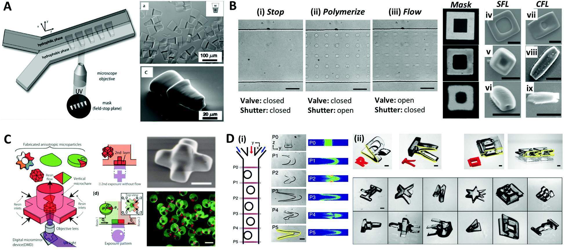 | ||
| Fig. 9 Optical lithography within microfluidic channels for complex-shaped microparticle synthesis. (A) Synthesis of amphiphilic Janus microparticles by continuous-flow lithography across two adjacent laminar streams. (B) Three states of the stop-flow lithography for particle synthesis (i–iii). A comparison of 10 μm tall particles with three different feature sizes (mask sizes are 6.25, 2.5 and 1.23 μm, respectively) formed using stop-flow lithography (SFL) (iv–vi), and continuous-flow lithography (CFL) (vii–ix); the scale bar is 10 μm. (C) Vertical flow lithography (VFL) for fabricating 3D anisotropic microparticles. By adjusting the combination of flow rate and UV exposure time, various 3D types of anisotropic particles were fabricated. (D) Fabrication of complex 3D-shaped particles with various combinations of photomasks and flow cross-sections formed by inertial flow. (i) Particles generated by inertial flow (from pillar to U shape) within the microfluidic channel. (ii) Fabricated complex-shaped microparticles. Reproduced with permission from ref. 140, 143, 150 and 151. Copyright 2007 American Chemical Society. Copyright 2007 Royal Society of Chemistry. Copyright 2015 Wiley-VCH. Copyright 2015 Nature Research. | ||
Recently, a modified flow lithography technique was proposed for the synthesis of microparticles with 3D anisotropy beyond 2D extruded shapes.147–149 Habasaki et al. presented vertical flow lithography (VFL), an application of stereo-lithography concepts to conventional flow lithography, which allowed better control over the fabrication of 3D anisotropic microparticles.150 In VFL, the light exposure and photocurable resin flow directions were aligned to enable the stacking of multiple photopolymerized layers with controlled 2D shape and thickness (Fig. 9C). This technique demonstrated the formation of multilayered, tapered, and angular compartmental microparticles. Paulsen et al. combined inertial flow shaping with SFL to generate the complex 3D-shaped polymer particles.151 At finite Reynolds numbers (Re = 10–100), pillars strategically positioned inside the microchannels created deterministic localized vortices and additive complex flow shapes depending on the pillar size, placement, number of sequential pillars and flow profiles, as illustrated in Fig. 9D(i). The 3D-shaped particles were created by the combination of geometry-induced flow deformation by fluid inertia and orthogonal masked UV polymerization (Fig. 9D(ii)).
3.4 Other methods
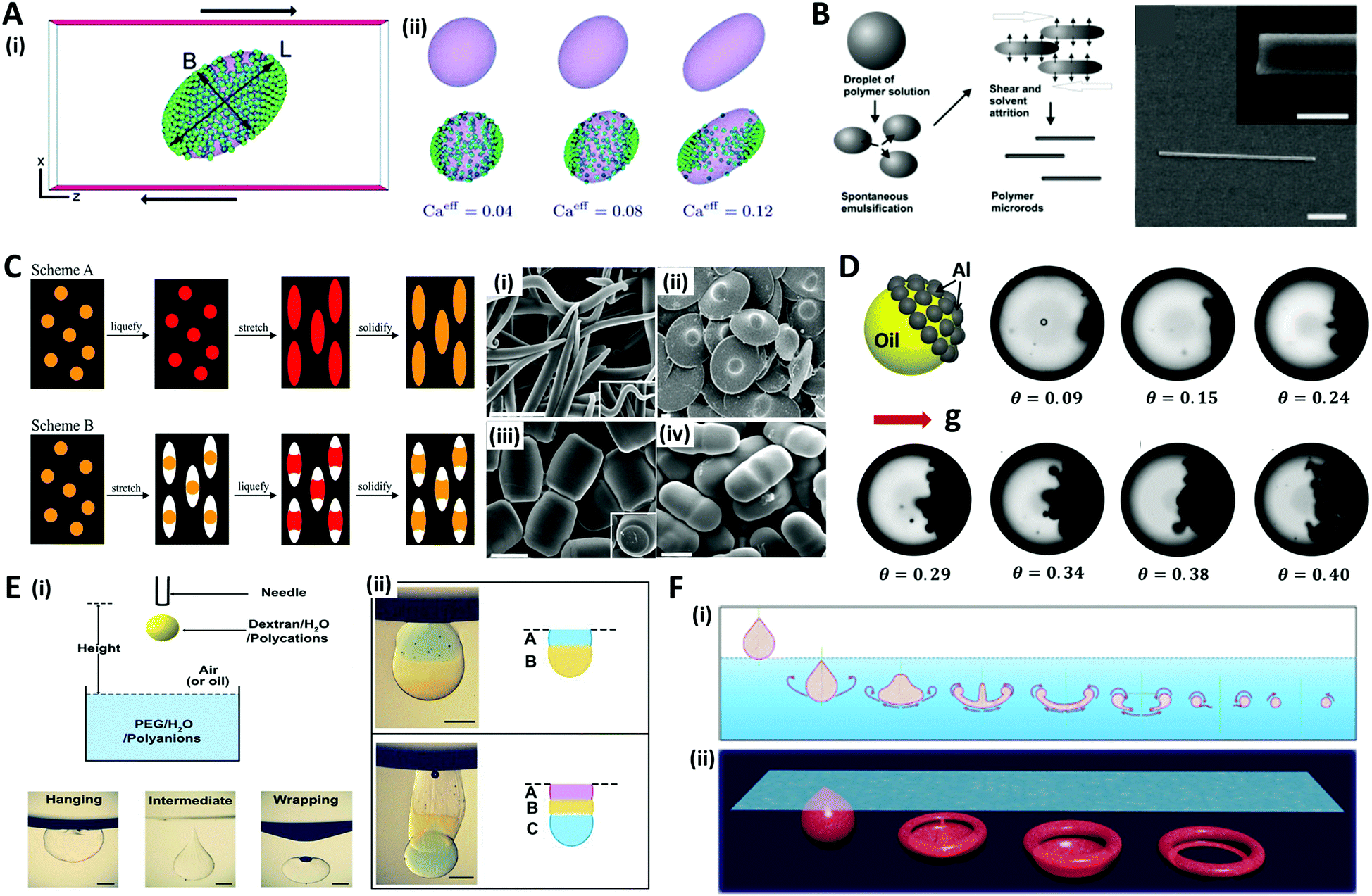
In addition to the aforementioned methods, various other approaches have been studied to shape microdroplets or microparticles. Although not all methods are covered herein, some representative methods are introduced, such as shear flow-driven, mechanical stretching, and gravity force-based methods.Droplets subjected to shear flow due to the opposite movement of two parallel plates show ellipsoidal deformation inclined in the shear direction (Fig. 10A(i)).152 Since Taylor introduced the theoretical model,153 the shear-driven deformation and inclination of droplets has been described as a function of capillary number (Ca = μoutGa/γ, where G is the shear rate, and a is the radius of the droplet) and the viscosity ratio of the continuous phase and dispersed phase (λ = μout/μin).154–156 The additional effects of nanoparticles and surfactants on shear-driven deformation were also investigated.157,158 For instance, Frijters et al. demonstrated the deformation and inclination of colloidal droplets and nanoparticle distribution due to shear flow through the numerical simulations (Fig. 10A(ii)).152 Alargova et al. combined the shear-driven deformation with the solvent evaporation method to fabricate rod-like particles with diameters between 0.5 and 3 μm, and lengths of tens of micrometers (Fig. 10B).159,160 The polymer emulsion droplets (solution of SU-8 in γ-butyrolactone (GBL)) suspended in an organic medium (such as glycerol or its mixtures with alcohols or glycols) were subjected to viscous shear induced by an impeller. During the shear-driven deformation process, the GBL, which is soluble in the organic medium, diffused out of the emulsion droplets and left behind the rod-like solid polymer. This rod-like shape could be solidified by crosslinking with UV light, and also transformed into a banana-shape by applying heat before crosslinking.161
 | ||
| Fig. 10 Other methods for fabricating microdroplets and microparticles. (A) Shear-driven deformation and inclination of droplet. (i) Schematic of shear flow system and deformed colloidal droplet. (ii) Examples of deformed droplet for various capillary numbers. (B) Process of rod-like polymer particle synthesis using the combination of shear-driven deformation and solvent evaporation methods; the scale bar is 10 μm (1 μm in the inset). (C) Film stretching method for particle shaping (scheme A and B) using film stretching with liquefaction and solidification of particles, and their results; (i) worm-, (ii) UFO-, (iii) barrel-, and (iv) pill-like particles; the scale bars are 2 μm. (D) Schematic and optical images of Janus droplets with different concentrations of Al particles (θ) accumulated by gravity effect. The diameter of the droplets ranges from 70 μm to 100 μm. (E) Stacking droplets beneath the liquid surface. (i) Schematic of the droplet impact system and three typical droplet modes after impacting liquid surface: hanging, intermediate, and wrapping. (ii) Horizontally stacked multiple Janus droplets fabricated in a hanging mode; the scale bars are 1 mm. (F) Mass production of shaped particles formed by vortex ring freezing. (i) Vortex ring formation process. (ii) Four typical vortex ring formed particles: teardrop-, jellyfish-, cap- and donut-ones. Reproduced with permission from ref. 152, 159, 163, 165, 166 and 172. Copyright 2012 Royal Society of Chemistry. Copyright 2004 Wiley-VCH. Copyright 2007 and 2020 National Academy of Sciences. Copyright 2018 Elsevier. Copyright 2016 Nature Research. | ||
On the other hand, Ho et al. applied mechanical stress by stretching the polymer film surrounding the polystyrene (PS) particles to make them into monodisperse ellipsoidal particles.162 The polymer film containing the particles was fabricated by evaporating a suspension of monodisperse PS particles and polyvinyl alcohol solution. This film was heated rapidly to 200 °C in an oil bath (liquefying of PS particles) and stretched to the predetermined extent in order to convert the spherical particles into ellipsoidal particles; the film was then cooled (scheme A in Fig. 10C). Champion et al. developed a similar method by changing the order of the liquefying and stretching steps (scheme B in Fig. 10C), and demonstrated that particles of various shapes could be generated by these two methods, such as worm-, UFO-, barrel-, and pill-like particles.163
Gravitational force is also one of the attractive options for creating asymmetrical shapes of microdroplets. Typically, when the density difference between the liquid and the particle constituting the colloidal droplet is large enough, the particle settles down to form a Janus colloidal droplet as depicted in Fig. 10D.164,165 Another approach is to use the phenomenon that appears when a falling droplet impacts on a liquid-free surface. The physics of droplet impact has been studied with various Weber numbers (We = ρdv2a/γ, where v is impact velocity) and Bond numbers (Bo = ρdga2/γ, where g is gravitational constant). When a droplet is impacted on the immiscible liquid surface, various modes such as hanging, intermediate, and wrapping are observed, which are depicted in Fig. 10E(i).166–168 Xie et al. used the hanging mode to produce multiple Janus droplets by stacking different droplets (Fig. 10E(ii)).166 When the impact velocity and droplet size were sufficiently small, the droplet hung stably beneath the interface between the air and liquid due to interfacial tension. Also, when a droplet impacted the miscible liquid surface, the droplet penetrated the surface, showing vortex generation (under low We) or jet formation (under high We).169–171 An et al. generated the torus-shaped particles in batch using the vortex ring formation phenomena (Fig. 10F).172 When a droplet passed the surface with a sufficient impact velocity, the droplet dissipated its energy by curling back the edge, resulting in deformation. During the deformation, liquid intermediates appeared with various intriguing non-spherical shapes including teardrops, jellyfish, caps, and donuts. By dripping a gellable nanoclay solution into the crosslinking buffer bath with precise control of the degree of crosslinking, various shapes of nanoclay vortex rings were gelled and formed vortex ring-derived particles. The mass-production of the particles was enabled with well-controlled size and shape by employing an electrospraying technique.
4. Applications of emulsions and microparticles
Various methods have been studied to control the shapes of microdroplets, which allow us to produce monodisperse emulsions or particles with complex structures on the micro/nano-scale in a high-throughput manner. Well-tailored emulsions or microparticles play important roles in fields such as biological, optical, robotic and environmental applications. Here, we cover the representative examples of these applications.4.1 Biological applications
Microdroplets are optimal templates for the encapsulation of bio-agents173–175 or chemicals,176–178 thus the solidified polymeric particles or shells are useful as carriers for drug delivery.179,180 The polymer carriers could prevent the loss of the drug component until a target position is reached, and release an optimized dose of the drug in a programmed sequence by layered structures.181–183 For example, Mou et al. fabricated Trojan-horse-like stimuli-responsive microcapsules for the versatile programmed and sequential release of drugs (Fig. 11A).184 The microcapsules composed of the stimuli-responsive polymers (chitosan, PEG-DA, and pNIPAm) with different triggering mechanisms could controllably load different contents in their separate capsule compartments and release each content in a predefined order and in a different manner. Shao et al. did in vivo antitumor tests to demonstrate the effectiveness of their near-infrared (NIR) light-triggered microcapsule, which inhibited tumor growth and prevented metastasis by releasing the encapsulated drug via NIR laser irradiation (Fig. 11B).185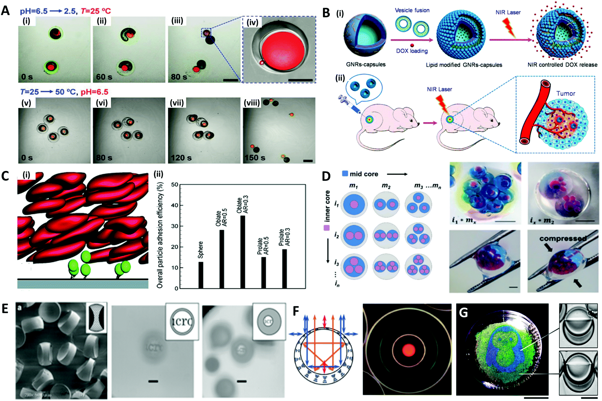 | ||
| Fig. 11 Biological and optical applications of shaped emulsions and microparticles. (A) Programmed sequential release of encapsulated components from Trojan-horse-like microcapsules. (i to iv) Snapshots of the acid-triggered burst release of the inner PEG-DA capsule by the decomposition of the outer chitosan capsule. (v to viii) Snapshots of the thermo-triggered burst release of the inner chitosan capsule by the shrinking of the outer pNIPAm capsule; the scale bars are 400 μm in (iii) and (vii), and 100 μm in (iv). (B) Near-infrared light (NIR)-induced drug release by gold nanorods (GNRs) embedded microcapsules. (i) Biocompatible GNRs-microcapsule encapsulating doxorubicin with the lipid bilayer controlled release of drug molecules mediated by NIR laser. (ii) In vivo anticancer therapy with the controlled release system of GNRs-microcapsule. (C) Near-wall dynamics of microparticles in three-dimensional simulation. (i) Rolling of microparticles along and adhering to a surface in the shear flow with flowing red blood cells. (ii) Overall particle adhesion efficiency for various types of particles. (D) Spatial patterning of complex emulsions for generating functional artificial cells. The hydrogel capsule provides mechanical stability; the scale bars are 1 mm. (E) Polymeric biconcave microlenses fabricated from microfluidic ternary emulsion droplets, and images through the biconcave lenses with magnification ratio of 0.1 (left) and 0.05 (right), respectively; the scale bars are 50 μm. (F) The optical image of planar-aligned cholesteric liquid crystal shells and schematic drawings of the reflection behavior in each shell. (G) Biphasic droplets with different interfacial curvatures causing a corresponding change in the iridescence, and penguin image patterned by droplets in a Petri dish using a light-responsive surfactant and photomask; ths scale bars are 2 cm (left) and 50 μm (right). Reproduced with permission from ref. 184, 185, 192, 196, 200, 205 and 206. Copyright 2014, 2018 and 2020 Wiley-VCH. Copyright 2015 Royal Society of Chemistry. Copyright 2019 Nature Research. | ||
In such drug delivery applications, microparticles are ultimately injected into a body and play their role by flowing through blood vessels. In doing so, the size and shape of the polymer carrier play an important role in the transport and adhesion to the target cell location, since they encounter various tortuous pathways within a body that are difficult to pass through during transportation.186–189 For instance, in order to pass through the interendothelial cell slits inside the spleen, the diameter of spherical particles must be less than 200 nm, but red blood cells with diameters of ∼10 μm, a large size relative to the spleen geometry, can pass through the spleen due to its non-spherical shape and flexibility.188,190 The shape of the particles could also affect their ability to release drugs through stable adsorption to the targeted vessel walls or cell membranes. Vahidkhah and Bagchi investigated the effect of particle shape on the margination, near-wall dynamics and adhesion within blood vessels via a three-dimensional numerical simulation.191 Their results revealed that the microparticles of different shapes interact differently with red blood cells, leading to different behaviours in the margination and adhesion of the particles, and oblate-shaped particles showed the highest overall particle adhesion efficiency (Fig. 11C).
The fields of manufacturing artificial cells and studying interactions of microparticles with real cells have also been emerging. As the techniques for the production of complex microdroplets have advanced, some researchers have tried to fabricate artificial cells that mimic the hierarchical structures of real cells as depicted in Fig. 11D.192 Cell-laden microdroplet production with microfluidics is another promising application of microdroplets.193 In particular, cell-laden microdroplets have been used for research on single-cells,194,195 3D organ/tumors,196,197 and stem cell therapy.198,199
4.2 Optical applications
Concave or convex interfaces of Janus or Cerberus emulsion droplets that scatter, diffract or interfere with light are attractive characteristics for optical applications. Nisisako et al. produced biconcave polymeric microlenses by first generating a SO-acrylate monomer-SO ternary emulsion droplet with a microfluidic device then removing the SO at both ends (Fig. 11E).200 The magnification ratio (i.e. observed image size over real image size) could be adjusted by the volume ratio of the ternary droplet. For example, a magnification ratio of a microlens produced from a droplet with a volume ratio of 2:1:2 was 0.1, whereas another microlens whose volume ratio was 1:3:1 showed a magnification ratio of 0.05.
Spherical emulsion droplets or shells composed of cholesteric liquid crystals could also manipulate their optical properties.201–204 For instance, microspheres of cholesteric (or chiral nematic) liquid crystals generated and manipulated the diverse photonic patterns due to selective reflection from a helical structure subject to continuously curved boundaries of liquid crystal shells (Fig. 11F).205 On the other hand, Goodling et al. also reported that Janus droplets consisting of heptane (refractive index = 1.37) and perfluorohexane (refractive index = 1.27), which are not liquid crystals, could also generate iridescence by total internal reflections and interference at microscale concave interfaces.206 The internal interfacial curvature of the Janus droplet caused a corresponding change in the iridescence, whereby the curvature modulation through the addition of light-responsive surfactants led to photo-patterning as depicted in Fig. 11G.
4.3 Robotic applications
The most representative application of microcapsules in robotics are micro-swimmers, also called micromotors, which are capable of converting chemical or external energy into mechanical motion to swim in the liquid.207–210 Self-propelled micromotors move autonomously in a specific direction, powered by a catalytic or photocatalytic chemical reaction, producing chemical gradients or gas bubble for self-propulsion.210–213To induce the directional movement of micromotors, precisely engineered anisotropies in 3D structures or in materials are necessary. A common way to make an anisotropic micromotor is to make Janus microparticles that contain catalytic materials, such as Pt, Ag, and TiO2, on one side of the microparticles, which are capable of performing tasks of inducing chemical reaction.214,215 Depending on the size of the microparticle, the driving mechanism of the propulsion can be varied; (i) the bubble propulsion on a scale of tens of micrometers, (ii) the diffusion and electrochemical driven propulsion on a scale of a few micrometers, and (iii) fast rotational diffusion without directionality on a submicrometer scale (Fig. 12A).215 As an example of bubble propulsion swimming, Chen et al. introduced the multifunctional micromotor using Janus emulsion templates incorporating Ag nanoparticles and Fe3O4 magnetic nanoparticles into each part, where TiO2 nanoparticles were also deposited on the surface of the micromotor (Fig. 12B).216 For the Janus micromotor, the bubble was generated under the catalysis of Ag nanoparticles and the micromotor was propelled as the bubbles continually left the concave surface. The propulsion of the motors could also be controlled by the magnetic force, which was controlled on demand via spatially changing the orientation of the magnetic field.212 Zou et al. also presented polymer micromotors with two distinct cores of Pt and Fe3O4 nanoparticle-dispersed hydrogels (Fig. 12C).217 When exposed to a H2O2 medium, the Pt cores provided propulsion by expelling bubbles produced from the catalytic decomposition of H2O2, while the Fe3O4 cores were impacted by the magnetic guidance. Benefiting from the close cooperation of these two cores, the micromotors achieved powerful propulsion and recyclability for the delivery of micro/macroscale objects. To demonstrate the delivery of the macroscale objects, the ring shape of the PDMS film, named ‘spaceship’, was made where the micromotors were encapsulated. Depending on the direction of the magnetic fields (dashed lines) the micromotors could move directionally to deliver the object with a powerful propulsive force.
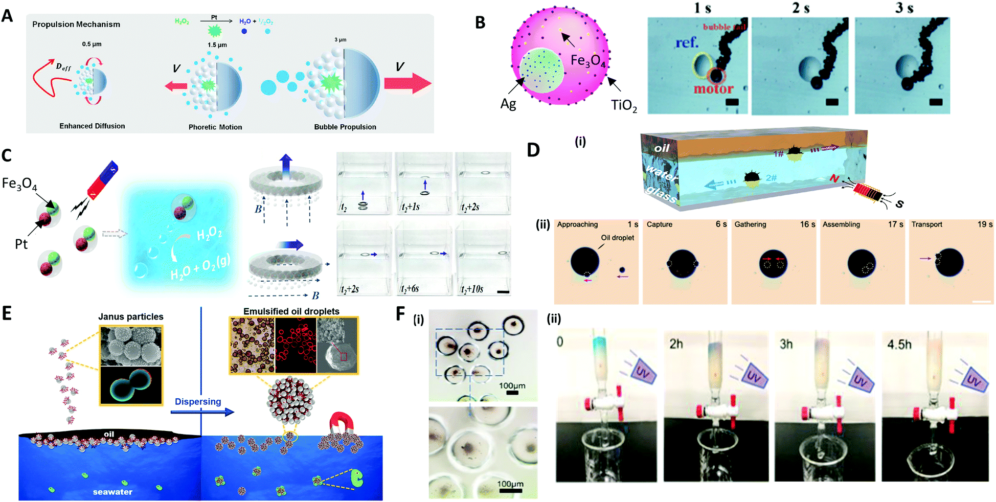 | ||
| Fig. 12 Applications of microparticles in robotics and environmental fields. (A) Size-dependent motility scenarios of self-propelled micromotors. (B) Movement control of the micromotor containing Ag, TiO2, and Fe3O4 nanoparticles; the scale bars are 60 μm. (C) Self-propulsion of the multifunctional micromotors embedding Pt and Fe3O4 nanoparticles directionally delivering a macroscale spaceship with magnetic guidance; the scale bar is 2 cm. (D) (i) The hollow structure of the microsubmarine, which propels under or above water depending on the fillings inside, and their movement are controlled via magnetic field. (ii) Removal of large oil droplet by the assembling of microsubmarines; the scale bar is 100 μm. (E) Dispersion of oil contaminants in seawater using a colloidal surfactant. (F) (i) TiO2 nanoparticles encapsulated in poly(anhydride) microcapsule. (ii) Cleaning of methylene blue solution in the flow microreactor while exposing to UV light. Reproduced with permission from ref. 12, 215–217, 219 and 223. Copyright 2016 and 2018 American Chemical Society. Copyright 2017 and 2020 Royal Society of Chemistry. Copyright 2019 and 2020 Elsevier. | ||
4.4 Environmental applications
Microparticles are also applied in dealing with pollution by taking advantage of their controllable structures, properties and motion. For instance, the directional movement of micromotors powered by the other external stimuli, in particular by magnetic forces, provides a definite trajectory with a high speed. This advantage has been utilized for water purification with anisotropic or Janus microparticles.12,218 Sun et al. reported a magnetic micro-submarine based on sunflower pollen grains for simultaneously removing oil and microplastic pollutants.12 The hollow structure of the micro-submarine allowed propelling under or above the water, depending on whether it was filled with water or oil inside (Fig. 12D(i)). The micro-submarine could deliver oil droplets 37 times larger than its own volume and effectively adsorbed floating oil via capillarity. Depending on the external magnetic field, the cooperative behavior of assembled micro-submarines achieved the transport of microplastics and oil droplets (Fig. 12D(ii)). Moreover, the colloidal surfactants made of amphiphilic Janus microparticles were utilized as an effective remedy for oil spill accidents (Fig. 12E).219 Particularly, the various methods of making colloidal surfactants with biocompatible materials have been introduced.220–222 Thus, biocompatible and less toxic colloidal surfactants could be able to replace conventional chemical surfactants and achieve water purification in an environmentally friendly manner.Hydrogel microcapsules composed of photocatalytic nanoparticles exhibit unique properties, including permeation, purification, and the catalytic reaction of molecular species.223 Photocatalytic TiO2 and ZnO nanoparticles encapsulated in the poly(methacrylic acid) microcapsules were used to remove organic pollutants. Due to the high surface area of photocatalytic nanomaterials and the adsorption properties of the hydrogel shell itself, the microcapsule effectively removed methylene blue organic material (Fig. 12F(i)). Flow microreactors based on the hydrogel capsules enabled the direct adsorption, degradation and separation of pollutants (Fig. 12F(ii)).
5. Conclusion and outlook
In this review, various passive and active strategies for generating and functionalizing microdroplets in various forms, and their corresponding applications, are introduced. The passive methods, such as batch emulsification, solvent evaporation and microfluidic systems, are advantageous for the relatively large-scale production of the microdroplets, since their shapes are predominantly determined by internal thermodynamics and chemical phenomena. On the other hand, the active method deforms the shape of the microdroplets by applying an external force such as an electric or a magnetic force, which is advantageous for generating droplets of more complex shapes. Well-engineered emulsions and microparticles fabricated from microdroplets using these strategies have great potential in areas such as energy, optics, and robotics.The technical limitations of the passive and active production method, or a lack of understanding of the mechanism, limit the available shapes of the droplets or the materials to be used. In the passive method, the shape of the droplet is very sensitive to factors such as the solution concentration or added materials in working solutions, so the shape should be delicately manipulated to obtain the target shape. Although the active method allows the formation of more complex shapes of the droplets, it also has limitations with regard to the applicable materials, since only those materials that match the applied external force can be chosen (e.g., ferrofluid for the magnetic method). Due to the high dependency on UV-polymerization in converting the microdroplet templates into microparticles, the selectability of materials is also limited. Therefore, in order to break through these hurdles, the research on new microdroplets with unconventional shapes and also the mechanisms underlying their formation should be continued.
The limitations mentioned above would be the reasons why it is difficult to find commercialized products despite the magnitude of research being conducted on various types of functional microdroplets. Thus, the remaining important challenge associated with the functional microdroplets is to develop the usefulness of these microdroplets into actual practical applications. For instance, research on the application of microdroplet systems to drug delivery upon target release has been continuously explored for the past decades, but it is still rare to see the commercialized products in the medical field. The technology for releasing the materials to the desired area has already been extensively investigated, and now it is necessary to broaden the perspective, such as manufacturing biocompatible materials, collecting the vehicle once used, or reusing it. On the other hand, most of the self-propelled micromotors are based on the metal materials, which use toxic H2O2 as a chemical fuel, thereby limiting their actual use in environmental applications. The future motors need to add a new aspect to convert the materials into bioorganic materials that use non-toxic chemical fuels, which could provide high potential for biological or environmental uses.
Another important challenge is to scale up the production of microdroplets. While there have been significant advances in structure-handing strategies, attempts to mass-produce, assemble, and induce the clustering movement of microdroplets remain limited to date. This may be the reason most microparticles are applied in biomedical fields dealing with phenomena on a relatively small scale in a variety of forms. On the other hand, concerns are lacking in the larger scale areas, such as energy, the environment, and the robotics field, and accordingly, practical applications have not yet been achieved. For instance, even though self-propelled microparticles have been developed for oil or microplastic removal, it is not enough to remove a large amount of oil leaking from the actual environment, and the swimmers themselves can become pollutants even after capturing the oil, so the technology for collecting them must also be properly developed. From this point of view, the direction of future research should go toward the mass-production of the microdroplets with high reliability, uniformity, and fast production on a macro-scale, that is, from hundreds of thousands to even more than trillions of droplets. Only then can it be practically applied to fields with high added value in the future, such as environmental or energy issues. To this end, the manufacturing technology on the micron-scale also needs to be further developed.
After a better understanding of the above aspects, actual industrial technologies could be more accurately derived and practically implemented in the future. Although more challenging problems remain, based on the already developed technologies and understanding of basic research, the microdroplets will evolve in a direction that is helpful to humanity.
Conflicts of interest
There are no conflicts to declare.Acknowledgements
J. L. thanks to the support by Basic Science Research Program through the National Research Foundation of Korea (NRF) grant funded by the Ministry of Science, ICT & Future Planning (NRF-2020R1A2C3010568).Notes and references
- A. B. Theberge, F. Courtois, Y. Schaerli, M. Fischlechner, C. Abell, F. Hollfelder and W. T. Huck, Angew. Chem., Int. Ed., 2010, 49, 5846–5868 CrossRef CAS PubMed.
- C.-H. Choi, S.-M. Kang, S. H. Jin, H. Yi and C.-S. Lee, Langmuir, 2015, 31, 1328–1335 CrossRef CAS PubMed.
- I. J. Joye and D. J. McClements, Curr. Opin. Colloid Interface Sci., 2014, 19, 417–427 CrossRef CAS.
- H. Duan, D. Wang, N. S. Sobal, M. Giersig, D. G. Kurth and H. Möhwald, Nano Lett., 2005, 5, 949–952 CrossRef CAS PubMed.
- I. Danielsson and B. Lindmann, Colloids Surf., 1981, 3, 391–392 CrossRef CAS.
- M. Gradzielski, Curr. Opin. Colloid Interface Sci., 2008, 13, 263–269 CrossRef CAS.
- P. H. Keen, N. K. Slater and A. F. Routh, Langmuir, 2012, 28, 1169–1174 CrossRef CAS PubMed.
- G. M. Radulova, T. G. Slavova, P. A. Kralchevsky, E. S. Basheva, K. G. Marinova and K. D. Danov, Colloids Surf., A, 2018, 559, 351–364 CrossRef CAS.
- S. Thakur, N. M. Das, S. Kumar, A. K. Dasmahapatra and D. Bandyopadhyay, Nanoscale Adv., 2020, 2, 1613–1624 RSC.
- G. M. Eichenbaum, P. F. Kiser, A. V. Dobrynin, S. A. Simon and D. Needham, Macromolecules, 1999, 32, 4867–4878 CrossRef CAS.
- X.-J. Ju and L.-Y. Chu, in Microfluidics for Pharmaceutical Applications, Elsevier, 2019, pp. 217–280 Search PubMed.
- M. Sun, W. Chen, X. Fan, C. Tian, L. Sun and H. Xie, Appl. Mater. Today, 2020, 20, 100682 CrossRef.
- E. Dickinson, Trends Food Sci. Technol., 2012, 24, 4–12 CrossRef CAS.
- T. Hoar and J. Schulman, Nature, 1943, 152, 102–103 CrossRef CAS.
- G. Verhoeckx, P. De Bruyn and J. T. G. Overbeek, J. Colloid Interface Sci., 1987, 119, 409–421 CrossRef CAS.
- G. M. El Maghraby, M. F. Arafa and E. A. Essa, in Applications of Nanocomposite Materials in Drug Delivery, Elsevier, 2018, pp. 787–803 Search PubMed.
- J. Guzowski, P. M. Korczyk, S. Jakiela and P. Garstecki, Soft Matter, 2012, 8, 7269–7278 RSC.
- M. S. Abbasi, H. Farooq, H. Ali, A. H. Kazim, R. Nazir, A. Shabbir, S. Cho, R. Song and J. Lee, Materials, 2020, 13, 2984 CrossRef CAS PubMed.
- A. Mikkelsen, K. Khobaib, F. K. Eriksen, K. J. Måløy and Z. Rozynek, Soft Matter, 2018, 14, 5442–5451 RSC.
- S. Akbari, T. Pirbodaghi, R. D. Kamm and P. T. Hammond, Lab Chip, 2017, 17, 2067–2075 RSC.
- X. Lu, L. Miao, W. Gao, Z. Chen, K. J. McHugh, Y. Sun, Z. Tochka, S. Tomasic, K. Sadtler and A. Hyacinthe, Sci. Transl. Med., 2020, 12, eaaz6606 CrossRef CAS PubMed.
- M. Weiss, J. P. Frohnmayer, L. T. Benk, B. Haller, J.-W. Janiesch, T. Heitkamp, M. Börsch, R. B. Lira, R. Dimova and R. Lipowsky, Nat. Mater., 2018, 17, 89–96 CrossRef CAS PubMed.
- J.-W. Kim, A. Fernández-Nieves, N. Dan, A. S. Utada, M. Marquez and D. A. Weitz, Nano Lett., 2007, 7, 2876–2880 CrossRef CAS PubMed.
- P. H. Keen, N. K. Slater and A. F. Routh, Langmuir, 2014, 30, 1939–1948 CrossRef CAS PubMed.
- K. L. Thompson, M. Williams and S. P. Armes, J. Colloid Interface Sci., 2015, 447, 217–228 CrossRef CAS PubMed.
- Z. Yu, Y. Lan, R. M. Parker, W. Zhang, X. Deng, O. A. Scherman and C. Abell, Polym. Chem., 2016, 7, 5996–6002 RSC.
- S. Carregal-Romero, M. Ochs, P. Rivera-Gil, C. Ganas, A. M. Pavlov, G. B. Sukhorukov and W. J. Parak, J. Controlled Release, 2012, 159, 120–127 CrossRef CAS PubMed.
- G. Gyulai, A. Magyar, J. Rohonczy, J. Orosz, M. Yamasaki, S. Bősze and É. Kiss, Express Polym. Lett., 2016, 10, 216 CrossRef CAS.
- T. Kanai, D. Lee, H. C. Shum, R. K. Shah and D. A. Weitz, Adv. Mater., 2010, 22, 4998–5002 CrossRef CAS PubMed.
- Y. Zhao, Z. Xie, H. Gu, L. Jin, X. Zhao, B. Wang and Z. Gu, NPG Asia Mater., 2012, 4, e25 CrossRef.
- F. He, M. J. Zhang, W. Wang, Q. W. Cai, Y. Y. Su, Z. Liu, Y. Faraj, X. J. Ju, R. Xie and L. Y. Chu, Adv. Mater. Technol., 2019, 4, 1800687 CrossRef.
- T. Nisisako, T. Ando and T. Hatsuzawa, Small, 2014, 10, 5116–5125 CAS.
- W. Wang, M.-J. Zhang and L.-Y. Chu, Acc. Chem. Res., 2014, 47, 373–384 CrossRef CAS PubMed.
- L. Ge, J. Cheng, D. Wei, Y. Sun and R. Guo, Langmuir, 2018, 34, 7386–7395 CrossRef CAS PubMed.
- D. J. Sukovich, S. C. Kim, N. Ahmed and A. R. Abate, Analyst, 2017, 142, 4618–4622 RSC.
- L. D. Zarzar, V. Sresht, E. M. Sletten, J. A. Kalow, D. Blankschtein and T. M. Swager, Nature, 2015, 518, 520–524 CrossRef CAS PubMed.
- L. Ge, J. Li, S. Zhong, Y. Sun, S. E. Friberg and R. Guo, Soft Matter, 2017, 13, 1012–1019 RSC.
- D. Wei, L. Ge, S. Lu, J. Li and R. Guo, Langmuir, 2017, 33, 5819–5828 CrossRef CAS PubMed.
- L. Ge, H. Jin, X. Li, D. Wei and R. Guo, Langmuir, 2019, 35, 3490–3497 CrossRef CAS PubMed.
- H. Hasinovic and S. E. Friberg, Langmuir, 2011, 27, 6584–6588 CrossRef CAS PubMed.
- H. Hasinovic, S. E. Friberg and G. Rong, J. Colloid Interface Sci., 2011, 354, 424–426 CrossRef CAS PubMed.
- L. Ge, W. Shao, S. Lu and R. Guo, Soft Matter, 2014, 10, 4498–4505 RSC.
- D. P. Curran and J. A. Gladysz, Handbook of Fluorous Chemistry, Wiley-VCH, 2004 Search PubMed.
- G. Shakya, S. E. Hoff, S. Wang, H. Heinz, X. Ding and M. A. Borden, Sci. Adv., 2020, 6, eaaz7188 CrossRef CAS PubMed.
- N. Andersson, B. Kronberg, R. Corkery and P. Alberius, Langmuir, 2007, 23, 1459–1464 CrossRef CAS PubMed.
- K. H. Ku, J. M. Shin, H. Yun, G. R. Yi, S. G. Jang and B. J. Kim, Adv. Funct. Mater., 2018, 28, 1802961 CrossRef.
- S. Liu, R. Deng, W. Li and J. Zhu, Adv. Funct. Mater., 2012, 22, 1692–1697 CrossRef CAS.
- H. Cui, Z. Chen, S. Zhong, K. L. Wooley and D. J. Pochan, Science, 2007, 317, 647–650 CrossRef CAS PubMed.
- R. Deng, F. Liang, W. Li, S. Liu, R. Liang, M. Cai, Z. Yang and J. Zhu, Small, 2013, 9, 4099–4103 CrossRef CAS PubMed.
- D. Klinger, C. X. Wang, L. A. Connal, D. J. Audus, S. G. Jang, S. Kraemer, K. L. Killops, G. H. Fredrickson, E. J. Kramer and C. J. Hawker, Angew. Chem., 2014, 126, 7138–7142 CrossRef.
- S. G. Jang, D. J. Audus, D. Klinger, D. V. Krogstad, B. J. Kim, A. Cameron, S.-W. Kim, K. T. Delaney, S.-M. Hur and K. L. Killops, J. Am. Chem. Soc., 2013, 135, 6649–6657 CrossRef CAS PubMed.
- K. H. Ku, J. M. Shin, M. P. Kim, C.-H. Lee, M.-K. Seo, G.-R. Yi, S. G. Jang and B. J. Kim, J. Am. Chem. Soc., 2014, 136, 9982–9989 CrossRef CAS PubMed.
- S. J. Jeon, G. R. Yi and S. M. Yang, Adv. Mater., 2008, 20, 4103–4108 CrossRef CAS.
- T. Higuchi, A. Tajima, K. Motoyoshi, H. Yabu and M. Shimomura, Angew. Chem., Int. Ed., 2009, 48, 5125–5128 CrossRef CAS PubMed.
- H. Yabu, S. Sato, T. Higuchi, H. Jinnai and M. Shimomura, J. Mater. Chem., 2012, 22, 7672–7675 RSC.
- R. Deng, H. Li, F. Liang, J. Zhu, B. Li, X. Xie and Z. Yang, Macromolecules, 2015, 48, 5855–5860 CrossRef CAS.
- K. H. Ku, Y. Kim, G.-R. Yi, Y. S. Jung and B. J. Kim, ACS Nano, 2015, 9, 11333–11341 CrossRef CAS PubMed.
- S. Liu, X. Li, L. Hu, S. Deng, W. Zhang, P. Liu and Y. Zhang, Langmuir, 2020, 36, 3821–3825 CrossRef CAS PubMed.
- B. M. Discher, Y.-Y. Won, D. S. Ege, J. C. Lee, F. S. Bates, D. E. Discher and D. A. Hammer, Science, 1999, 284, 1143–1146 CrossRef CAS PubMed.
- R. C. Hayward, A. S. Utada, N. Dan and D. A. Weitz, Langmuir, 2006, 22, 4457–4461 CrossRef CAS PubMed.
- H. C. Shum, J.-W. Kim and D. A. Weitz, J. Am. Chem. Soc., 2008, 130, 9543–9549 CrossRef CAS PubMed.
- H. C. Shum, Y. j. Zhao, S. H. Kim and D. A. Weitz, Angew. Chem., Int. Ed., 2011, 50, 1648–1651 CrossRef CAS PubMed.
- H. U. Kim, Y. J. Lim, H. J. Lee, N. J. Lee and K. W. Bong, Lab Chip, 2020, 20, 74–83 RSC.
- J. Nunes, K. P. Herlihy, L. Mair, R. Superfine and J. M. DeSimone, Nano Lett., 2010, 10, 1113–1119 CrossRef CAS PubMed.
- C. H. Choi, J. Lee, K. Yoon, A. Tripathi, H. A. Stone, D. A. Weitz and C. S. Lee, Angew. Chem., 2010, 122, 7914–7918 CrossRef.
- J. P. Rolland, B. W. Maynor, L. E. Euliss, A. E. Exner, G. M. Denison and J. M. DeSimone, J. Am. Chem. Soc., 2005, 127, 10096–10100 CrossRef CAS PubMed.
- R. A. Petros, P. A. Ropp and J. M. DeSimone, J. Am. Chem. Soc., 2008, 130, 5008–5009 CrossRef CAS PubMed.
- S. E. Gratton, S. S. Williams, M. E. Napier, P. D. Pohlhaus, Z. Zhou, K. B. Wiles, B. W. Maynor, C. Shen, T. Olafsen and E. T. Samulski, Acc. Chem. Res., 2008, 41, 1685–1695 CrossRef CAS PubMed.
- J. Xu, D. H. Wong, J. D. Byrne, K. Chen, C. Bowerman and J. M. DeSimone, Angew. Chem., Int. Ed., 2013, 52, 6580–6589 CrossRef CAS PubMed.
- C.-H. Choi, J. Kim, S.-M. Kang, J. Lee and C.-S. Lee, Langmuir, 2013, 29, 8447–8451 CrossRef CAS PubMed.
- C.-H. Choi, B. Lee, J. Kim, J.-O. Nam, H. Yi and C.-S. Lee, ACS Appl. Mater. Interfaces, 2015, 7, 11393–11401 CrossRef CAS PubMed.
- C. H. Choi, J. M. Jeong, S. M. Kang, C. S. Lee and J. Lee, Adv. Mater., 2012, 24, 5078–5082 CrossRef CAS PubMed.
- S. Jung and H. Yi, Chem. Mater., 2015, 27, 3988–3998 CrossRef CAS.
- K. J. McHugh, T. D. Nguyen, A. R. Linehan, D. Yang, A. M. Behrens, S. Rose, Z. L. Tochka, S. Y. Tzeng, J. J. Norman and A. C. Anselmo, Science, 2017, 357, 1138–1142 CrossRef CAS PubMed.
- A. S. Utada, E. Lorenceau, D. R. Link, P. D. Kaplan, H. A. Stone and D. Weitz, Science, 2005, 308, 537–541 CrossRef CAS PubMed.
- L. Y. Chu, A. S. Utada, R. K. Shah, J. W. Kim and D. A. Weitz, Angew. Chem., 2007, 119, 9128–9132 CrossRef.
- H. N. Joensson and H. Andersson Svahn, Angew. Chem., Int. Ed., 2012, 51, 12176–12192 CrossRef CAS PubMed.
- A. Utada, L.-Y. Chu, A. Fernandez-Nieves, D. Link, C. Holtze and D. Weitz, MRS Bull., 2007, 32, 702–708 CrossRef CAS.
- K. Doufène, C. Tourné-Péteilh, P. Etienne and A. Aubert-Pouëssel, Langmuir, 2019, 35, 12597–12612 CrossRef PubMed.
- C. L. Mou, W. Wang, Z. L. Li, X. J. Ju, R. Xie, N. N. Deng, J. Wei, Z. Liu and L. Y. Chu, Adv. Sci., 2018, 5, 1700960 CrossRef PubMed.
- H. Kim, S. M. Jo, F. Meng, Y. Guo, H. Thérien-Aubin, R. Golestanian, K. Landfester and E. Bodenschatz, Adv. Funct. Mater., 2020, 30, 2006019 CrossRef CAS.
- G. M. Whitesides and A. D. Stroock, Phys. Today, 2001, 54, 42–48 CrossRef CAS.
- A. C. Glavan, R. V. Martinez, E. J. Maxwell, A. B. Subramaniam, R. M. Nunes, S. Soh and G. M. Whitesides, Lab Chip, 2013, 13, 2922–2930 RSC.
- M. M. Islam, A. Loewen and P. B. Allen, Sci. Rep., 2018, 8, 1–11 Search PubMed.
- R. Song, M. S. Abbasi and J. Lee, Microfluid. Nanofluidics, 2019, 23, 92 CrossRef.
- K. Maeda, H. Onoe, M. Takinoue and S. Takeuchi, Adv. Mater., 2012, 24, 1340–1346 CrossRef CAS PubMed.
- W. Wang, R. Xie, X.-J. Ju, T. Luo, L. Liu, D. A. Weitz and L.-Y. Chu, Lab Chip, 2011, 11, 1587–1592 RSC.
- S. H. Kim, J. W. Shim and S. M. Yang, Angew. Chem., Int. Ed., 2011, 50, 1171–1174 CrossRef CAS PubMed.
- S. Seiffert, M. B. Romanowsky and D. A. Weitz, Langmuir, 2010, 26, 14842–14847 CrossRef CAS PubMed.
- J. R. Melcher and G. I. Taylor, Annu. Rev. Fluid. Mech., 1969, 1, 111–146 CrossRef.
- Z. Jiang, Y. Gan and Y. Luo, Phys. Fluids, 2020, 32, 053301 CrossRef CAS.
- M. S. Abbasi, H. Farooq, H. Ali, A. H. Kazim, R. Nazir, A. Shabbir, S. Cho, R. Song and J. Lee, Materials, 2020, 13, 2984 CrossRef CAS.
- M. S. Abbasi, R. Song, S. Cho and J. Lee, Micromachines, 2020, 11, 942 CrossRef PubMed.
- A. Behjatian and A. Esmaeeli, Acta Mech., 2015, 226, 2581 CrossRef.
- A. Behjatian and A. Esmaeeli, Phys. Rev. E: Stat., Nonlinear, Soft Matter Phys., 2013, 88, 033012 CrossRef PubMed.
- P. Soni, V. A. Juvekar and V. M. Naik, J. Electrost., 2013, 71, 471–477 CrossRef.
- M. S. Abbasi, R. Song, J. Kim and J. Lee, J. Electrost., 2017, 85, 11–22 CrossRef CAS.
- M. S. Abbasi, R. Song, S. M. Kim, H. Kim and J. Lee, Soft Matter, 2019, 15, 2328–2335 RSC.
- G. E. Pradillo, H. Karani and P. M. Vlahovska, Soft Matter, 2019, 15, 6564–6570 RSC.
- Q. Brosseau and P. M. Vlahovska, Phys. Rev. Lett., 2017, 119, 034501 CrossRef.
- M. S. Abbasi, R. Song, H. Kim and J. Lee, Soft Matter, 2019, 15, 2292–2300 RSC.
- M. S. Abbasi, R. Song and J. Lee, Soft Matter, 2019, 15, 8905–8911 RSC.
- S. Nudurupati, M. Janjua, N. Aubry and P. Singh, Electrophoresis, 2008, 29, 1164–1172 CrossRef CAS PubMed.
- S. Nudurupati, M. Janjua, P. Singh and N. Aubry, Soft Matter, 2010, 6, 1157–1169 RSC.
- P. Dommersnes, Z. Rozynek, A. Mikkelsen, R. Castberg, K. Kjerstad, K. Hersvik and J. Otto Fossum, Nat. Commun., 2013, 4, 2066 CrossRef.
- A. Mikkelsen, K. Khobaib, F. K. Eriksen, K. J. Maloy and Z. Rozynek, Soft Matter, 2018, 14, 5442–5451 RSC.
- M. Ouriemi and P. M. Vlahovska, J. Fluid Mech., 2014, 751, 106–120 CrossRef CAS.
- M. Ouriemi and P. M. Vlahovska, Langmuir, 2015, 31, 6298–6305 CrossRef CAS PubMed.
- M. Cui, T. Emrick and T. P. Russell, Science, 2013, 342, 460–463 CrossRef CAS PubMed.
- P. Atten, J. Electrost., 1993, 30, 259–269 CrossRef CAS.
- S. Mhatre, S. Deshmukh and R. M. Thaokar, Phys. Fluids, 2015, 27, 092106 CrossRef.
- Y. Jia, Y. Ren, W. Liu, L. Hou, Y. Tao, Q. Hu and H. Jiang, Lab Chip, 2016, 16, 4313–4318 RSC.
- Z. Rozynek, A. Mikkelsen, P. Dommersnes and J. O. Fossum, Nat. Commun., 2014, 5, 3945 CrossRef CAS PubMed.
- Z. Rozynek, R. Castberg, A. Kalicka, P. Jankowski and P. Garstecki, Arch. Mech., 2015, 67, 385–399 Search PubMed.
- Z. Rozynek and A. Jozefczak, Eur. Phys. J. Spec. Top., 2016, 225, 741–756 CrossRef CAS.
- T. Y. He and J. V. Jokerst, Biomater. Sci., 2020, 8, 5555–5573 RSC.
- L. L. Zhang, J. W. Huang, T. Si and R. X. Xu, Expet Rev. Med. Dev., 2012, 9, 595–612 CrossRef CAS.
- S. Bhaskar, K. M. Pollock, M. Yoshida and J. Lahann, Small, 2010, 6, 404–411 CrossRef CAS PubMed.
- K.-H. Roh, D. C. Martin and J. Lahann, Nat. Mater., 2005, 4, 759–763 CrossRef CAS PubMed.
- K. Ulbrich, K. Hola, V. Subr, A. Bakandritsos, J. Tucek and R. Zboril, Chem. Rev., 2016, 116, 5338–5431 CrossRef CAS.
- C. A. Zentner, A. Concellon and T. M. Swager, ACS Cent. Sci., 2020, 6, 1460–1466 CrossRef CAS.
- Y. Chen, Y. K. Bai, S. B. Chen, J. P. Jup, Y. Q. Li, T. M. Wang and Q. H. Wang, ACS Appl. Mater. Interfaces, 2014, 6, 13334–13338 CrossRef CAS PubMed.
- S. Odenbach, Ferrofluids: magnetically controllable fluids and their applications, Springer, 2008 Search PubMed.
- S. Afkhami, A. J. Tyler, Y. Renardy, M. Renardy, T. G. St Pierre, R. C. Woodward and J. S. Riffle, J. Fluid Mech., 2010, 663, 358–384 CrossRef CAS.
- P. Rowghanian, C. D. Meinhart and O. Campas, J. Fluid Mech., 2016, 802, 245–262 CrossRef CAS.
- Y. Filali, M. Er-Riani and M. El Jarroudi, Int. J. Nonlin. Mech., 2018, 99, 173–181 CrossRef.
- L. D. Landau and E. M. Lifshitz, in Electrodynamics of Continuous Media, ed. L. D. Landau and E. M. Lifshitz, Pergamon, Amsterdam, 1984, vol. 8, p. 11 Search PubMed.
- G. P. Zhu, N. T. Nguyen, R. V. Ramanujan and X. Y. Huang, Langmuir, 2011, 27, 14834–14841 CrossRef CAS PubMed.
- O. Lavrova, Dr. rer. nat. Thesis, Otto von Guericke University, Magdeburg, 2006 Search PubMed.
- J. V. I. Timonen, M. Latikka, L. Leibler, R. H. A. Ras and O. Ikkala, Science, 2013, 341, 253–257 CrossRef CAS PubMed.
- T. Vieu and C. Walter, J. Fluid Mech., 2018, 840, 455–497 CrossRef CAS.
- M. H. Hu, H. J. Butt, K. Landfester, M. B. Bannwarth, S. Wooh and H. Therien-Aubin, ACS Nano, 2019, 13, 3015–3022 CrossRef CAS PubMed.
- X. J. Fan, X. G. Dong, A. C. Karacakol, H. Xie and M. Sitti, Proc. Natl. Acad. Sci. U.S.A., 2020, 117, 27916–27926 CrossRef CAS PubMed.
- S. H. Tan and N. T. Nguyen, Phys Rev E, 2011, 84, 036317 CrossRef PubMed.
- S. Kahkeshani and D. Di Carlo, Lab Chip, 2016, 16, 2474–2480 RSC.
- Q. F. Yan, S. H. Xuan, X. H. Ruan, J. Wu and X. L. Gong, Microfluid. Nanofluidics, 2015, 19, 1377–1384 CrossRef.
- S. H. Tan, N. T. Nguyen, L. Yobas and T. G. Kang, J. Micromech. Microeng., 2010, 20, 045004 CrossRef.
- V. B. Varma, R. G. Wu, Z. P. Wang and R. V. Ramanujan, Lab Chip, 2017, 17, 3514–3525 RSC.
- D. Dendukuri, D. C. Pregibon, J. Collins, T. A. Hatton and P. S. Doyle, Nat. Mater., 2006, 5, 365–369 CrossRef CAS PubMed.
- D. Dendukuri, T. A. Hatton and P. S. Doyle, Langmuir, 2007, 23, 4669–4674 CrossRef CAS PubMed.
- D. C. Pregibon, M. Toner and P. S. Doyle, Science, 2007, 315, 1393–1396 CrossRef CAS PubMed.
- S. E. Chung, W. Park, H. Park, K. Yu, N. Park and S. Kwon, Appl. Phys. Lett., 2007, 91, 041106 CrossRef.
- D. Dendukuri, S. S. Gu, D. C. Pregibon, T. A. Hatton and P. S. Doyle, Lab Chip, 2007, 7, 818–828 RSC.
- R. F. Shepherd, P. Panda, Z. Bao, K. H. Sandhage, T. A. Hatton, J. A. Lewis and P. S. Doyle, Adv. Mater., 2008, 20, 4734–4739 CrossRef CAS.
- D. Baah, T. Donnell, J. Tigner and T. Floyd-Smith, Particuology, 2014, 14, 91–97 CrossRef CAS.
- S.-H. Wang, P.-H. Wang, I. M. Hsieh and C.-C. Hsieh, J. Taiwan Inst. Chem. Eng., 2018, 93, 103–108 CrossRef CAS.
- K. Choi, M. Salehizadeh, R. B. Da Silva, N. Hakimi, E. Diller and D. K. Hwang, Soft Matter, 2017, 13, 7255–7263 RSC.
- J. H. Jang, D. Dendukuri, T. A. Hatton, E. L. Thomas and P. S. Doyle, Angew. Chem., Int. Ed., 2007, 46, 9027–9031 CrossRef CAS PubMed.
- J. Lolsberg, A. Cinar, D. Felder, G. Linz, S. Djeljadini and M. Wessling, Small, 2019, 15, 1901356 CrossRef PubMed.
- S. Habasaki, W. C. Lee, S. Yoshida and S. Takeuchi, Small, 2015, 11, 6391–6396 CrossRef CAS PubMed.
- K. S. Paulsen, D. Di Carlo and A. J. Chung, Nat. Commun., 2015, 6, 1–9 Search PubMed.
- S. Frijters, F. Gunther and J. Harting, Soft Matter, 2012, 8, 6542–6556 RSC.
- G. I. Taylor, Proc. R. Soc. London, Ser. A, 1934, 146, 501–523 CAS.
- M. Minale, Rheol. Acta, 2010, 49, 789–806 CrossRef CAS.
- P. Van Puyvelde, A. Vananroye, R. Cardinaels and P. Moldenaers, Polymer, 2008, 49, 5363–5372 CrossRef CAS.
- N. Ioannou, H. Liu and Y. H. Zhang, J. Comput. Sci., 2016, 17, 463–474 CrossRef.
- J. J. M. Janssen, A. Boon and W. G. H. Agterof, Colloids Surf., A, 1994, 91, 141–148 CrossRef CAS.
- K. Feigl, D. Megias-Alguacil, P. Fischer and E. J. Windhab, Chem. Eng. Sci., 2007, 62, 3242–3258 CrossRef CAS.
- R. G. Alargova, K. H. Bhatt, V. N. Paunov and O. D. Velev, Adv. Mater., 2004, 16, 1653–1657 CrossRef CAS.
- R. G. Alargova, V. N. Paunov and O. D. Velev, Langmuir, 2006, 22, 765–774 CrossRef CAS PubMed.
- C. Fernandez-Rico, M. Chiappini, T. Yanagishima, H. de Sousa, D. G. A. L. Aarts, M. Dijkstra and R. P. A. Dullens, Science, 2020, 369, 950–955 CrossRef CAS PubMed.
- C. C. Ho, A. Keller, J. A. Odell and R. H. Ottewill, Colloid Polym. Sci., 1993, 271, 469–479 CrossRef CAS.
- J. A. Champion, Y. K. Katare and S. Mitragotri, Proc. Natl. Acad. Sci. U. S. A., 2007, 104, 11901–11904 CrossRef CAS PubMed.
- H. Wang, Y. X. Liu, Z. Y. Chen, L. Y. Sun and Y. J. Zhao, Sci. Adv., 2020, 6, eaay1438 CrossRef CAS PubMed.
- M. Q. Li and D. Q. Li, J. Colloid Interface Sci., 2018, 532, 657–665 CrossRef CAS PubMed.
- G. H. Xie, J. Forth, S. P. Zhu, B. A. Helms, P. D. Ashby, H. C. Shum and T. P. Russell, Proc. Natl. Acad. Sci. U.S.A., 2020, 117, 8360–8365 CrossRef CAS PubMed.
- E. Yakhshi-Tafti, H. J. Cho and R. Kumar, J. Colloid Interface Sci., 2010, 350, 373–376 CrossRef CAS PubMed.
- Z. Z. Che and O. K. Matar, Soft Matter, 2018, 14, 1540–1551 RSC.
- J. S. Lee, S. J. Park, J. H. Lee, B. M. Weon, K. Fezzaa and J. H. Je, Nat. Commun., 2015, 6, 1–8 Search PubMed.
- M. Hsiao, S. Lichter and L. G. Quintero, Phys. Fluids, 1988, 31, 3560–3562 CrossRef.
- A. Saha, Y. J. Wei, X. Y. Tang and C. K. Law, J. Fluid Mech., 2019, 875, 842–853 CrossRef CAS.
- D. An, A. Warning, K. G. Yancey, C. T. Chang, V. R. Kern, A. K. Datta, P. H. Steen, D. Luo and M. L. Ma, Nat. Commun., 2016, 7, 1–10 Search PubMed.
- T. P. Lagus and J. F. Edd, RSC Adv., 2013, 3, 20512–20522 RSC.
- K. G. Lee, T. J. Park, S. Y. Soo, K. W. Wang, B. H. Kim, J. H. Park, C. S. Lee, D. H. Kim and S. J. Lee, Biotechnol. Bioeng., 2010, 107, 747–751 CrossRef CAS PubMed.
- A. B. Theberge, F. Courtois, Y. Schaerli, M. Fischlechner, C. Abell, F. Hollfelder and W. T. S. Huck, Angew. Chem., Int. Ed., 2010, 49, 5846–5868 CrossRef CAS.
- S. Jung, R. Song, J. Kim, J. H. Ko and J. Lee, Langmuir, 2020, 36, 1515–1522 CrossRef CAS.
- H. Lee, C. H. Choi, A. Abbaspourrad, C. Wesner, M. Caggioni, T. Zhu and D. A. Weitz, ACS Appl. Mater. Interfaces, 2016, 8, 4007–4013 CrossRef CAS.
- M. Mazur, Langmuir, 2008, 24, 10414–10420 CrossRef CAS PubMed.
- R. Langer, Science, 1990, 249, 1527–1533 CrossRef CAS PubMed.
- D. S. Kohane, Biotechnol. Bioeng., 2007, 96, 203–209 CrossRef CAS PubMed.
- Y. J. Wang, Y. Yan, J. W. Cui, L. Hosta-Rigau, J. K. Heath, E. C. Nice and F. Caruso, Adv. Mater., 2010, 22, 4293–4297 CrossRef CAS PubMed.
- D. R. K. Weerasuriya, W. P. S. L. Wijesinghe and R. M. G. Rajapakse, Mater. Sci. Eng., C, 2017, 71, 206–213 CrossRef CAS.
- K. L. Jarvis, T. J. Barnes and C. A. Prestidge, Adv. Colloid Interface Sci., 2012, 175, 25–38 CrossRef CAS PubMed.
- C. L. Mou, W. Wang, Z. L. Li, X. J. Ju, R. Xie, N. N. Deng, J. Wei, Z. Liu and L. Y. Chu, Adv. Sci., 2018, 5, 1700960 CrossRef PubMed.
- J. X. Shao, M. J. Xuan, T. Y. Si, L. R. Dai and Q. He, Nanoscale, 2015, 7, 19092–19098 RSC.
- A. B. Jindal, Int. J. Pharm., 2017, 532, 450–465 CrossRef CAS.
- Y. W. Yang, D. Nie, Y. Liu, M. R. Yu and Y. Gan, Drug Discov. Today, 2019, 24, 575–583 CrossRef CAS PubMed.
- J. A. Champion, Y. K. Katare and S. Mitragotri, J. Controlled Release, 2007, 121, 3–9 CrossRef CAS PubMed.
- W. Q. Wang, K. Gaus, R. D. Tilley and J. J. Gooding, Mater. Horizon, 2019, 6, 1538–1547 RSC.
- S. M. Moghimi, A. C. Hunter and J. C. Murray, Pharmacol. Rev., 2001, 53, 283–318 CAS.
- K. Vahidkhah and P. Bagchi, Soft Matter, 2015, 11, 2097–2109 RSC.
- J. Li, D. K. Baxani, W. D. Jamieson, W. Xu, V. G. Rocha, D. A. Barrow and O. K. Castell, Adv. Sci., 2020, 7, 1901719 CrossRef CAS PubMed.
- W. Li, L. Y. Zhang, X. H. Ge, B. Y. Xu, W. X. Zhang, L. L. Qu, C. H. Choi, J. H. Xu, A. Zhang, H. M. Lee and D. A. Weitz, Chem. Soc. Rev., 2018, 47, 5646–5683 RSC.
- M. Li, M. van Zee, C. T. Riche, B. Tofig, S. D. Gallaher, S. S. Merchant, R. Damoiseaux, K. Goda and D. Di Carlo, Small, 2018, 14, 1803315 CrossRef PubMed.
- X. Y. Chen, R. Shen, S. D. Liu, X. Xiao, J. Yan, Y. Q. Zhang, Z. Y. Jiang, B. Q. Nie and J. Liu, Anal. Methods, 2020, 12, 3250–3259 RSC.
- Q. S. Chen, S. Utech, D. Chen, R. Prodanovic, J. M. Lin and D. A. Weitz, Lab Chip, 2016, 16, 1346–1349 RSC.
- P. Agarwal, H. Wang, M. R. Sun, J. S. Xu, S. T. Zhao, Z. G. Liu, K. J. Gooch, Y. Zhao, X. B. Lu and X. M. He, ACS Nano, 2017, 11, 6691–6702 CrossRef CAS PubMed.
- D. K. Kang, M. M. Ali, K. X. Zhang, E. J. Pone and W. A. Zhao, TrAC, Trends Anal. Chem., 2014, 58, 145–153 CrossRef CAS.
- J. M. Rabanel, X. Banquy, H. Zouaoui, M. Mokhtar and P. Hildgen, Biotechnol. Prog., 2009, 25, 946–963 CrossRef CAS PubMed.
- T. Nisisako, T. Ando and T. Hatsuzawa, Small, 2014, 10, 5116–5125 CAS.
- M. Schwartz, G. Lenzini, Y. Geng, P. B. Ronne, P. Y. A. Ryan and J. P. F. Lagerwall, Adv. Mater., 2018, 30, 1707382 CrossRef PubMed.
- X. Wang, Y. Zhou, V. Palacio-Betancur, Y. K. Kim, L. Delalande, M. Tsuei, Y. Yang, J. J. de Pablo and N. L. Abbott, Langmuir, 2019, 35, 16312–16323 CrossRef CAS PubMed.
- M. Urbanski, C. G. Reyes, J. Noh, A. Sharma, Y. Geng, V. S. R. Jampani and J. P. F. Lagerwall, J. Phys. Condens. Matter, 2017, 29, 133003 CrossRef.
- T. Lopez-Leon and A. Fernandez-Nieves, Colloid Polym. Sci., 2011, 289, 345–359 CrossRef CAS.
- Y. Geng, J. H. Jang, K. G. Noh, J. Noh, J. P. F. Lagerwall and S. Y. Park, Adv. Opt. Mater., 2018, 6, 1700923 CrossRef.
- A. E. Goodling, S. Nagelberg, B. Kaehr, C. H. Meredith, S. I. Cheon, A. P. Saunders, M. Kolle and L. D. Zarzar, Nature, 2019, 566, 523–527 CrossRef CAS PubMed.
- W. Gao, A. Pei, R. Dong and J. Wang, J. Am. Chem. Soc., 2014, 136, 2276–2279 CrossRef CAS.
- F. Peng, Y. Tu, Y. Men, J. C. van Hest and D. A. Wilson, Adv. Mater., 2017, 29, 1604996 CrossRef PubMed.
- H. Wang and M. Pumera, Nanoscale, 2017, 9, 2109–2116 RSC.
- C. Chen, F. Mou, L. Xu, S. Wang, J. Guan, Z. Feng, Q. Wang, L. Kong, W. Li and J. Wang, Adv. Mater., 2017, 29, 1603374 CrossRef PubMed.
- V. Sridhar, B. W. Park and M. Sitti, Adv. Funct. Mater., 2018, 28, 1704902 CrossRef.
- A. X. Lu, Y. Liu, H. Oh, A. Gargava, E. Kendall, Z. Nie, D. L. DeVoe and S. R. Raghavan, ACS Appl. Mater. Interfaces, 2016, 8, 15676–15683 CrossRef CAS PubMed.
- C. Zhou, P. Zhu, Y. Tian, M. Xu and L. Wang, ACS Nano, 2019, 13, 6319–6329 CrossRef CAS PubMed.
- P. S. Schattling, M. A. Ramos-Docampo, V. n. Salgueiriño and B. Städler, ACS Nano, 2017, 11, 3973–3983 CrossRef CAS PubMed.
- X. Ma, S. Jang, M. N. Popescu, W. E. Uspal, A. Miguel-López, K. Hahn, D.-P. Kim and S. Sánchez, ACS Nano, 2016, 10, 8751–8759 CrossRef CAS PubMed.
- A. Chen, X.-h. Ge, J. Chen, L. Zhang and J.-H. Xu, Lab Chip, 2017, 17, 4220–4224 RSC.
- M. Zou, J. Wang, Y. Yu, L. Sun, H. Wang, H. Xu and Y. Zhao, ACS Appl. Mater. Interfaces, 2018, 10, 34618–34624 CrossRef CAS PubMed.
- S.-H. Kim, A. Abbaspourrad and D. A. Weitz, J. Am. Chem. Soc., 2011, 133, 5516–5524 CrossRef CAS PubMed.
- Y. J. Hou, Y. M. Li, L. S. Wang, D. F. Chen, M. T. Bao and Z. N. Wang, J. Colloid Interface Sci., 2019, 556, 54–64 CrossRef CAS PubMed.
- D. Chen, E. Amstad, C. X. Zhao, L. H. Cai, J. Fan, Q. S. Chen, M. T. Hai, S. Koehler, H. D. Zhang, F. X. Liang, Z. Z. Yang and D. A. Weitz, ACS Nano, 2017, 11, 11978–11985 CrossRef CAS PubMed.
- Z. Sun, C. J. Yang, F. Wang, B. H. Wu, B. Q. Shao, Z. C. Li, D. Chen, Z. Z. Yang and K. Liu, Angew. Chem., Int. Ed., 2020, 59, 9365–9369 CrossRef CAS PubMed.
- S. T. Xie, S. Chen, Q. F. Zhu, X. Li, D. Wang, S. T. Shen, M. L. Jin, G. F. Zhou, Y. G. Zhu and L. L. Shui, ACS Appl. Mater. Interfaces, 2020, 12, 26374–26383 CrossRef CAS PubMed.
- J. Liu, H. Chen, X. Shi, S. Nawar, J. G. Werner, G. Huang, M. Ye, D. A. Weitz, A. A. Solovev and Y. Mei, Environ. Sci.: Nano, 2020, 7, 656–664 RSC.
| This journal is © The Royal Society of Chemistry 2021 |