
 Open Access Article
 This Open Access Article is licensed under a Creative Commons Attribution-Non Commercial 3.0 Unported Licence
Enhanced resistance to decay of imprinted nanopatterns in thin films by bare nanoparticles compared to polymer-grafted nanoparticles†
Sonal
Bhadauriya
 a,
Asritha
Nallapaneni
a,
Xiaoteng
Wang
a,
Jianan
Zhang
b,
Ali
Masud
c,
Michael R.
Bockstaller
b,
Abdullah M.
Al-Enizi
d,
Christopher M.
Stafford
e,
Jack F.
Douglas
*e and
Alamgir
Karim
*c
a,
Asritha
Nallapaneni
a,
Xiaoteng
Wang
a,
Jianan
Zhang
b,
Ali
Masud
c,
Michael R.
Bockstaller
b,
Abdullah M.
Al-Enizi
d,
Christopher M.
Stafford
e,
Jack F.
Douglas
*e and
Alamgir
Karim
*c
aDepartment of Polymer Engineering, University of Akron, Akron, Ohio 44325, USA. E-mail: akarim3@central.uh.edu
bDepartment of Materials Science and Engineering, Carnegie Mellon University, Pittsburgh, Pennsylvania 15213, USA
cDepartment of Chemical and Biomolecular Engineering, University of Houston, Houston, Texas 77204, USA
dDepartment of Chemistry, College of Science, King Saud University, Riyadh 11451, Saudi Arabia
eMaterials Science and Engineering Division, National Institute of Standards and Technology, Gaithersburg, Maryland 20899, USA. E-mail: jack.douglas@nist.gov
First published on 19th July 2021
Abstract
We extend a previous study on the influence of nanoparticles on the decay of nanoimprinted polymer film patterns to compare the effects of “bare” silica (SiO2) nanoparticles and SiO2 nanoparticles with grafted polymer layers having the same chemical composition as the polymer matrix. This method involves nanoimprinting substrate-supported polymer films using a pattern replicated from a digital versatile disc (DVD), and then annealing the patterned polymer nanocomposite films at elevated temperatures to follow the decay of the topographic surface pattern with time by atomic force microscopy imaging after quenching. We quantified the relaxation of the pattern height (“slumping”) and determined the relaxation time τ for this pattern decay process as a function of nanoparticle filler type and concentration to determine how nanoparticle additives influence relative film stability. Attractive interactions between the bare nanoparticles and the polymer matrix significantly enhance the thermal resilience of the nanopatterns to decay, compared to those of the particle brushes, wherein the particle core interactions are screened from the matrix via the brush layer. A novel aspect of this method is that it readily lends itself to in situ film relaxation measurements in a manufacturing context. We observe that the relaxation time of the pattern relaxation exhibits entropy–enthalpy compensation in the free energy parameters governing the pattern relaxation process as a function of temperature, irrespective of the NP system used, consistent with our previous experimental and computational studies.
Numerous previous studies have shown that the addition of nanoparticles (NPs) (grafted with polymers to aid in dispersion or bare NPs without grafted polymers) to a polymer matrix alters the glass transition temperature Tg and the viscoelastic behavior of the resultant composite material.1–3 The underlying reason for this change has been attributed to the altered segmental chain relaxation in the polymer interfacial layer around the NPs.4 The interaction strength between the NPs and the polymer matrix chains mainly depends on the surface modification of the NPs (unmodified vs. polymer grafted) and this quantity is one of the key parameters responsible for the property changes observed in nanocomposites.5,6 Nanocomposites for which the surface tethered polymers are chemically identical to the matrix polymer are often termed “athermal” blends where the core–core interaction is assumed to be screened by the polymer chains tethered to the NP surface. Our group recently investigated the decay of imprinted features of nanocomposite thin films upon thermal exposure (“slumping”) in an athermal blend system7 where the addition of grafted NPs led to an increased stability of the imprinted features above a certain “compensation temperature”, Tcomp, observed to be in the vicinity of the glass transition temperature of the pure polymer matrix. The compensation temperature refers to a constant of proportionality relating the activation enthalpy and activation entropy compensation in Arrhenius relaxation processes reasonably described by transition state theory. If grafting polymer chains to the NPs is not an option (for economic and/or chemistry related issues), many applications are relegated to chemistries that have highly attractive NP–polymer interactions8–10 to aid in the dispersion of the NPs. Therefore, it is imperative to also understand how the addition of bare NPs, having attractive interactions with the matrix, influences the slumping behavior of imprinted films, given the significant influence that grafted NPs have been shown to have on the relaxation of imprinted films.
Here we present a detailed investigation of the slumping behavior of imprinted poly(methyl methacrylate) (PMMA) (Mn = 3.1 kg mol−1, where Mn is the number average molecular mass) thin films containing two different NP additives, unmodified bare silica (b-SiO2) NPs (4 to 5 nm in radius) and PMMA-grafted SiO2 (g-SiO2) NPs (Mn of the grafted chains ≈19.4 kg mol−1 and 7.7 (±2) nm radius). The bulk Tg value of the PMMA matrix (Tg,bulk) was approximately equal to 97.2 (±0.2) °C, as estimated by ellipsometry.7 The glass transition of the composite films containing 20% (mass fraction relative to the matrix mass) bare SiO2 NP PMMA and grafted SiO2 NPs in the PMMA matrix was 100.3 (±0.5) °C and 99.7 (±0.1) °C, respectively, determined via ellipsometry.11 A pre-patterned polydimethylsiloxane (PDMS) elastomeric stamp was used to imprint parallel lines and space patterns on our neat PMMA thin films and composite thin films containing varying mass fractions of b-SiO2 NPs and g-SiO2 NPs (5%, 10% and 20% by mass relative to the matrix mass). Samples after imprinting (PDMS peeled off) had an initial pattern height, Ho of 135 (±5.5) nm and a width of 353 (±0.5) nm. The imprinted films had a residual layer thickness of 36.5 (±6.5) nm underneath the pattern. Patterned samples were characterized ex situ by atomic force microscopy (AFM) in terms of the pattern height (H) after the samples were subjected to different annealing temperatures for various exposure times (t). The evolution of the pattern height, H, as a function of exposure time was normalized to the initial pattern height to yield the corresponding decay curves.
The normalized height decay curves comparing 5% and 20% mass fraction (relative to the matrix mass) for the two NP systems, b-SiO2 and g-SiO2, can be seen in Fig. 1. It is evident that the bare b-SiO2 NPs exhibited substantially better pattern retention than g-SiO2 NPs. The increase in pattern retention for the b-SiO2 system can be attributed to the strong interactions between the matrix chains and the unmodified b-SiO2 NP surface.8 On the other hand, for the g-SiO2 NP system, these interacting forces are screened due to the chains grafted on the NP surface, reducing the pattern retention. We also found that as the concentration of the NP additive was increased, better pattern retention was seen, as observed previously for composite films with polymer grafted nanoparticles.7
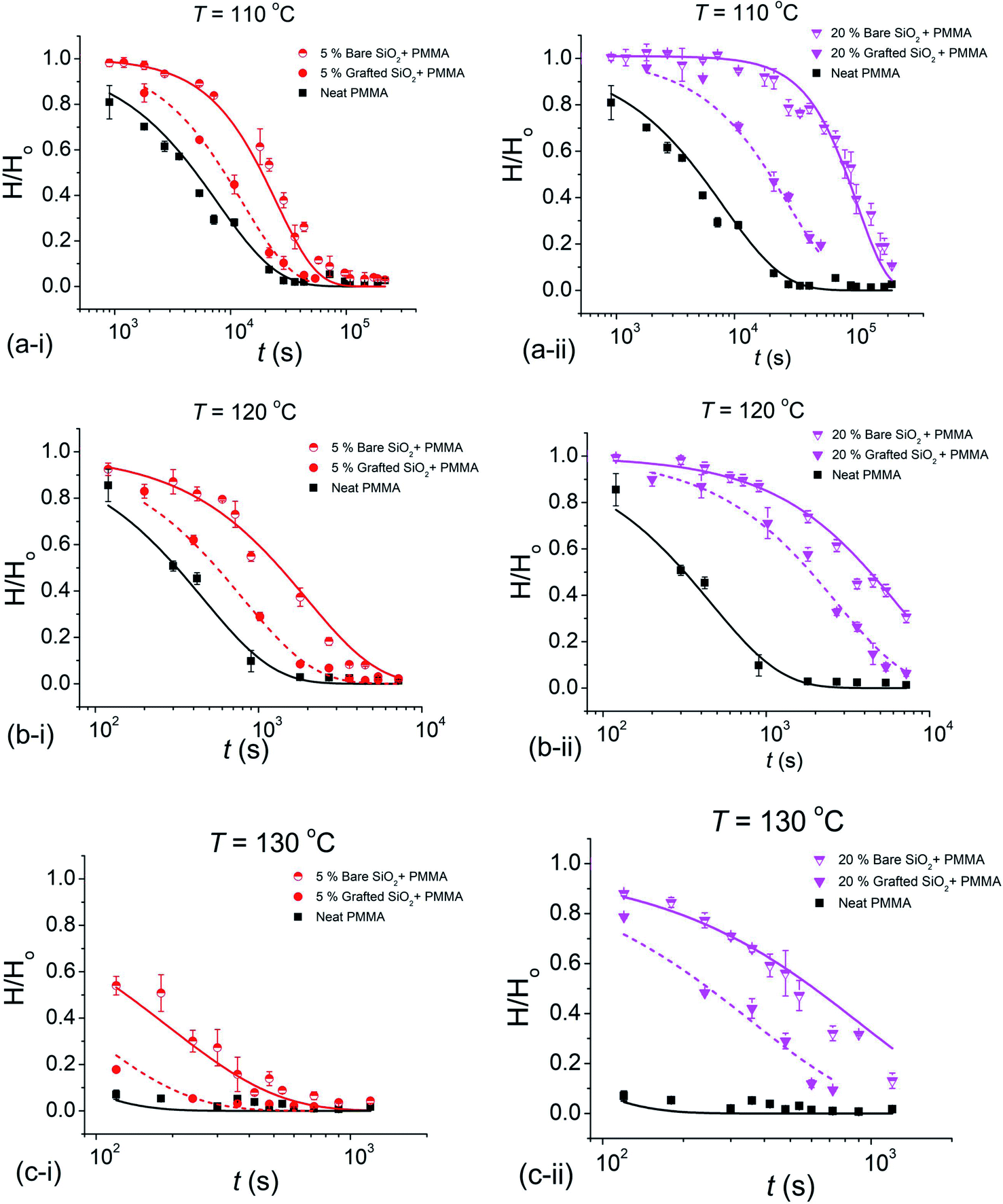 | ||
| Fig. 1 Decay curves for the normalized pattern height, H(t)/Ho at 110 °C (a-i, a-ii), 120 °C (b-i, b-ii) and 130 °C (c-i, c-ii) for 5% and 20% filled (mass fraction relative to the matrix) b-SiO2 NP and g-SiO2 NP filled polymer films. Solid and dashed lines passing through the data points show the generalized exponential fit, and the error bars denote the experimental uncertainty of the measurement. | ||
The relaxation data for the normalized pattern height, H/Ho, were fit to a “generalized exponential” function, H/Ho ≈ exp[−(t/τ)β], where t is the waiting time or “exposure time”, τ is the “slumping” relaxation time constant and the exponent β quantifies the degree of non-exponentiality of the relaxation process.
The decay curves shown in Fig. 1 indicate a significant stabilization of the imprinted pattern as the volume fraction ϕ of the NPs is increased, which is markedly pronounced for bare nanoparticles. Fitting the reduced pattern height H/Ho to the generalized exponential relaxation function noted above yielded an estimate of the slumping relaxation time τ and β, which quantifies the shape of the relaxation function. Fig. 2 and 3 show the temperature dependence of β and τ for both b-SiO2 and g-SiO2 NP filled polymer films. As can be seen from Fig. 2, for the g-SiO2 NP filled polymer film, β approaches a simple exponential relation (β ≈ 1) at all temperatures investigated. On the other hand, β increases above 1 at low temperatures, but converges to 1 at elevated temperatures for the b-SiO2 NP system. In our previous study,7 we observed β > 1 for clustered PMMA grafted titania nanoparticles at low temperatures. We emphasize that the b-SiO2 NPs used in the present study are relatively well dispersed, as shown in Fig. S1k–n (see the ESI†) and we do not find any significant clustering. We tentatively associate the values of β > 1 with highly attractive interactions between the b-SiO2 NPs and the PMMA matrix, but we must admit that the physical explanation for this unexpected phenomenon is not entirely clear.
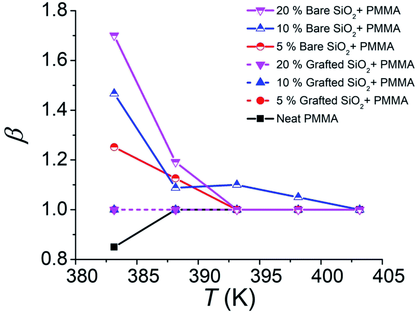 | ||
| Fig. 2 Variation of the non-exponential relaxation exponent β from the slumping relaxation curves as a function of the NP concentration: 5%, 10% and 20% (mass fractions relative to the matrix) b-SiO2 and g-SiO2 NPs in the PMMA matrix. Solid lines show the b-SiO2 NP system and dashed lines show observations on the g-SiO2 NP filled polymer film. Dashed lines for 5%, 10% and 20% g-SiO2 NPs are overlapping. | ||
 | ||
| Fig. 3 Temperature dependence of the relaxation time (τ) for 5%, 10% and 20% (mass fractions relative to the matrix) b-SiO2 and g-SiO2 NPs in the PMMA matrix. Lines (solid: b-SiO2 NP filled polymer film; dashed: g-SiO2 NP filled polymer film) indicate linear fits. | ||
Fig. 3 shows the temperature dependence of the relaxation time τ, whose temperature dependence can be approximated using a linear Arrhenius relation, τ = τ0![[thin space (1/6-em)]](https://www.rsc.org/images/entities/char_2009.gif) exp(Ea/RT) over the temperature range investigated. We observe three basic trends in our relaxation data: (1) as the concentration of the NP additive is increased, the relaxation time of the pattern decay increases; (2) for a given concentration, the relaxation time for the unmodified NP (b-SiO2) filled polymer film is higher than that of the grafted NP (g-SiO2) system; and (3) for both NP types, it seems that the extrapolation of these linear trends leads to a convergence point, similar to our previously observed results for the cluster grafted NP system.7 Extrapolations of the linear trends for b-SiO2 and g-SiO2 NP filled polymer films are shown in Fig. S1h and S2h (see the ESI†), respectively. We observe an approximate intersection point between 2.72 K−1 and 2.76 K−1 for the g-SiO2 NP filled polymer film and roughly between 2.96 K−1 and 3.03 K−1 for the b-SiO2 NP filled polymer film, corresponding to a Tcomp of ≈ 89.2 °C to 94.5 °C and ≈57.4 °C to 64.7 °C, respectively. As apparent in Fig. S1h (see the ESI†), the intersection of the linear trends is not clear for the b-SiO2 NP filled polymer film compared to that observed for the g-SiO2 NP filled polymer film in Fig. S2h.† A more robust way of ascribing and interpreting Tcomp utilizing the convergence plots would be to fully map out the transition region, i.e., the relaxation behavior below and above this characteristic temperature. Probing relaxation behavior for imprinted films below Tg is experimentally challenging due to long relaxation times. We recently probed the relaxation dynamics of wrinkled nanocomposite films and found the Tcomp to occur in the vicinity of the matrix's Tg.12 In the present work, the compensation temperature and the deviation range are reported by computing a range of intersection points given by compatible slopes for the linear trends. The Tcomp values reported from this rough estimation of the intersection points for g-SiO2 and b-SiO2 NP filled polymer films, respectively, are equal to ≈2 °C to 8 °C and 32.5 °C to 40 °C, which are lower than the bulk glass transition temperature, Tg,bulk ≈ 97.24 (±0.23) °C.
exp(Ea/RT) over the temperature range investigated. We observe three basic trends in our relaxation data: (1) as the concentration of the NP additive is increased, the relaxation time of the pattern decay increases; (2) for a given concentration, the relaxation time for the unmodified NP (b-SiO2) filled polymer film is higher than that of the grafted NP (g-SiO2) system; and (3) for both NP types, it seems that the extrapolation of these linear trends leads to a convergence point, similar to our previously observed results for the cluster grafted NP system.7 Extrapolations of the linear trends for b-SiO2 and g-SiO2 NP filled polymer films are shown in Fig. S1h and S2h (see the ESI†), respectively. We observe an approximate intersection point between 2.72 K−1 and 2.76 K−1 for the g-SiO2 NP filled polymer film and roughly between 2.96 K−1 and 3.03 K−1 for the b-SiO2 NP filled polymer film, corresponding to a Tcomp of ≈ 89.2 °C to 94.5 °C and ≈57.4 °C to 64.7 °C, respectively. As apparent in Fig. S1h (see the ESI†), the intersection of the linear trends is not clear for the b-SiO2 NP filled polymer film compared to that observed for the g-SiO2 NP filled polymer film in Fig. S2h.† A more robust way of ascribing and interpreting Tcomp utilizing the convergence plots would be to fully map out the transition region, i.e., the relaxation behavior below and above this characteristic temperature. Probing relaxation behavior for imprinted films below Tg is experimentally challenging due to long relaxation times. We recently probed the relaxation dynamics of wrinkled nanocomposite films and found the Tcomp to occur in the vicinity of the matrix's Tg.12 In the present work, the compensation temperature and the deviation range are reported by computing a range of intersection points given by compatible slopes for the linear trends. The Tcomp values reported from this rough estimation of the intersection points for g-SiO2 and b-SiO2 NP filled polymer films, respectively, are equal to ≈2 °C to 8 °C and 32.5 °C to 40 °C, which are lower than the bulk glass transition temperature, Tg,bulk ≈ 97.24 (±0.23) °C.
The apparent convergence of the relaxation time in Fig. 3 near a compensation temperature occurs when the change in the activation parameters (ΔEa and ΔSa) becomes equal, e.g., the relaxation appears to behave as if NPs had not been added (pure polymer). Indeed, we can see the near linearity between −ln(τo), which is linear in ΔSa in transition state theory, and Ea for both the unmodified b-SiO2 NP and grafted g-SiO2 NP filled polymer films from the data shown in Fig. 4. A similar compensation effect was observed previously for the relaxation of imprinted films with cluster grafted titania NPs.7 The linearity between the activation parameters of a relaxation process has taken various forms and nomenclatures: the Meyer–Neldel rule, the Constable–Cremer law, an isokinetic relationship, and the entropy–enthalpy compensation effect, as examples. We use the term entropy–enthalpy compensation (EEC) in this work. EEC is an empirical relationship arising in many condensed matter relaxation processes: viscosity of liquids,13 temperature dependence of fluidity,14 aqueous solubility of proteins and small molecules,15 shear viscosity of polymers16,17 solvent dynamics,18 antiplasticization by water,19 relaxation in polymer blends,20 desiccation tolerance in seeds,21 temperature dependent specific conductivity,22–24 relaxation of confined PDMS,25 oxygen diffusion in the Earth's mantle,26 heterogeneous catalysis,27–30 fouling in crude oil,31 high-frequency dynamics of mixtures,32etc. Despite decades of study, and its ubiquitous observation in diverse materials, the fundamental origin of EEC remains a topic of theoretical speculation. The most widely accepted interpretation of EEC is that it reflects the rapidly increasing number of paths crossing the transition state barrier in condensed matter relaxation as the barrier heights become large.33,34 Dyre33 has reviewed the various arguments for EEC and we have also discussed this phenomenon in our previous work.7 The existence of EEC requires a clear change in the activation energy (slope of the Arrhenius curve) and an unambiguous tendency for the family of curves to intersect at a common temperature even before any analysis of EEC is made, since otherwise the correlation of the activation energy and prefactor variations could be spurious. This type of analysis is also complicated by complex fluid effects that can make the temperature of relaxation processes and diffusion non-Arrhenius.
 | ||
| Fig. 4 Entropy−enthalpy compensation (EEC) plot showing the linear dependence between −ln(τo) and Ea for the b-SiO2 NP filled polymer film (left-filled violet pentagons, R2 ≈ 0.999) and g-SiO2 NP (crossed-center olive stars, R2 ≈ 0.999) filled polymer film. Solid lines represent the linear fits to the data. Dashed lines represent 95% confidence intervals. | ||
The investigation of the compensation phenomenon for pattern relaxation in imprinted films,7 and the problem of films having variable film thickness35 where polymer confinement is also involved, leads to the broader fundamental question: why do the activation parameters for a thermally induced pattern decay process linearly compensate each other? The driving force for pattern decay is the surface-energy driven viscous flow36–38 to reduce the overall surface area of the imprinted films. The activation energy Ea for the relaxation process decreases with increasing concentrations of NPs (both unmodified and grafted), whereas the prefactor, ln(τo), increases (or −ln(τo), decreases), which can be seen in Fig. S1i and j for the b-SiO2 NP system and S2i and j for the g-SiO2 NP system (see the ESI†). To address the occurrence of compensation in slumping relaxation dynamics, a combined theoretical and experimental approach is required. We may obtain an alternate perspective of the entropy–enthalpy compensation effect by plotting our relaxation time relative to the pure material, τr[τ(ϕ)/τ(ϕ = 0)], as a function of the filler volume fraction ϕ and a range of fixed temperatures shown in Fig. 5. It can be inferred from Fig. 5a that the b-SiO2 NP filled system shows a larger increase in the relaxation time of the patterned structure compared to the g-SiO2 NP system (Fig. 5b). The insets in Fig. 5a and b show the temperature dependence of the slope where it progressively decreases upon cooling and even approaches 0 as the temperature approaches Tcomp, which we estimate from the data in Fig. 5 to be near Tcomp ≈ 104 °C for the g-SiO2 NP system and 95 °C for the b-SiO2 NP system, where both these temperatures are close to Tg of the pure material. Specifically, we found Tg of our bulk PMMA material to be ≈ 97 °C, as reported previously.7 The strong attractive interaction between the b-SiO2 NPs and the matrix increases the activation energy of the composite as a whole,39 but the compensation temperature is observed to be near the glass transition temperature of the pure melt. In some studies investigating glass forming materials, the compensation temperature for relaxation was found to be closer to the Vogel–Fulcher–Tammann (VFT) temperature,40To, where this temperature is determined from fitting the viscosity (or relaxation time) data to the VFT relation, logη = A + B/(T − To). Tcomp is then estimated from our relaxation time data to be somewhat below (≈5 °C) the bulk Tg of the material.35 This is typical for previous observations of entropy–enthalpy compensation in glass-forming materials.40
 | ||
| Fig. 5 Relative relaxation time constant of slumping, τr[τ(ϕ)/τ(ϕ = 0)], as a function of the (a) b-SiO2 NPs and (b) g-SiO2 volume fraction, ϕ. The b-SiO2 NP system is shown as violet data points: 110 °C, left-filled square; 115 °C, left-filled circle; 120 °C, left-filled upward arrow; 125 °C, left-filled downward arrow; 130 °C, left-filled diamond. The g-SiO2 NP system is shown as green data points: 110 °C, centered-cross square; 115 °C, centered-cross circle; 120 °C, centered-cross upward arrow; 125 °C, centered-cross downward arrow; 130 °C, centered-cross diamond. Dashed and dotted lines denote linear fits to the data. The inset graph (left-filled violet pentagons for b-SiO2 NPs and centered-cross greed stars for g-SiO2 NPs) shows the temperature dependence of the slope and error bars denote the standard error of fitting. Tcomp ≈ 104 °C for g-SiO2 NP and ≈95 °C for b-SiO2 NP nanocomposite films, respectively. | ||
Conclusions
Understanding the decay of imprinted surface features on a polymer or a polymer nanocomposite thin film presents an important problem in the field of organic nanodevices and smart coatings. The decay behavior of imprinted features is highly influenced by varying the additive system (bare unmodified SiO2 nanoparticles compared to polymer-grafted SiO2 nanoparticles); additionally, an entropy–enthalpy compensation behavior is observed in the relaxation dynamics of both nanocomposite materials. Relaxation behavior of patterned polymer surfaces with additives interacting strongly with the matrix leads to a greater persistence of the pattern with time, i.e., greater pattern “stability” above a characteristic compensation temperature (estimated to be ≈104 °C for the grafted SiO2 nanoparticle system and ≈95 °C for the bare SiO2 nanoparticle system). The compensation temperature Tcomp was observed to be close to Tg of the neat polymer (≈97 °C), similar to our previous observations in nanocomposite films containing grafted nanoparticles.7 The entropy–enthalpy compensation effect is then observed in the pattern relaxation process, irrespective of the additive type, suggesting the robustness of the entropy–enthalpy compensation effect in the dynamics of filled films and films having varying film thickness.35 The relative ease of tracking the evolution of relief features imprinted on polymer films, both with and without filler particles and other additives, and for general film thickness should make this method useful in materials processing and in service life context where relatively non-invasive measurements can be performed on films in situ11 under conditions where residual stresses, moisture exposure and other complications may also exist.Experimental section
Poly(methyl methacrylate) (PMMA), Mn 3.1 kg mol−1, polydispersity 1.09 was purchased from Polymer Source (P9059-MMA, syndiotactic rich content >79%) and was used as received. In situ ellipsometry measurements to estimate the limiting bulk glass transition were reported previously for this PMMA,7 leading to a Tg,bulk = 97.2 (±0.2) °C. Unmodified bare SiO2 nanoparticles (b-SiO2 NPs) (4 nm to 5 nm nominal radius) were purchased from Nissan Chemicals and used as received. The solution is 30% (by mass) colloidal silica mono-dispersed in methyl isobutyl ketone (MIBK), specially catered towards acrylic resins (PMMA in our case) where the surface of this NP has hydroxyl groups, making it highly compatible with our matrix. The glass transition of the composite film containing 20% (mass fraction relative to the matrix mass) bare SiO2 NPs in the PMMA matrix was 100.3 (±0.5) °C, determined via ellipsometry.11 The synthesis of PMMA-grafted SiO2 NPs (g-SiO2 NPs) was performed utilizing surface-initiated atom transfer radical polymerization.41,42 The nanoparticles had an average radius of 7.7 (±2) nm after grafting, as measured by transmission electron microscopy (see ESI, Fig. S3†). The number average molecular mass (Mn) of the grafted PMMA chains was measured to be 19.4 kg mol−1 using gel permeation chromatography with a polydispersity of 1.17. The glass transition of the composite film containing 20% (mass fraction relative to the matrix mass) PMMA grafted SiO2 NPs in the PMMA matrix was 99.7 (±0.1) °C, determined via ellipsometry.11 The number-average molecular weight (Mn) and molecular weight distribution were determined by size exclusion chromatography (SEC). The SEC was conducted with a Waters 515 pump and Waters 410 differential refractometer using PSS columns (Styrogel 105, 103, and 102 Å) in THF as an eluent at 35 °C and at a flow rate of 1 mL min−1. Linear PMMA standards were used for calibration. Prior to SEC analysis, samples were etched with HF (to remove the silica core) in a polypropylene vial for 20 h, then neutralized with ammonium hydroxide, and subsequently dried with magnesium sulfate before SEC injection. It is noted that the neutralization process has to be conducted with caution under liquid nitrogen to dissipate heat. The PMMA grafting density was estimated to be ≈0.65 chains per nm2 based on the organic mass loss from TGA (see ESI, Fig. S4†).43Neat PMMA solution and composite solutions for the b-SiO2 NP system and g-SiO2 NP system (5%, 10% and 20% mass fraction relative to the matrix mass) were prepared in acetone. The solutions were then flow coated onto silicon substrates; the silicon substrates were first cleaned by ultraviolet ozone treatment for 2 h. The thickness of the films was 104 (±6.5) nm as measured by spectral reflectometry (F-20 Ultraviolet Thin Film Analyzer; Filmetrics, Inc.). Patterned, crosslinked poly(dimethylsiloxane) (PDMS) elastomer stamps (thickness ≈ 1 mm, 20:1 curing ratio) were made by casting the prepolymer against the patterned inset of commercial polycarbonate digital versatile discs (Sony, DVD-R, pitch λ ≈ 750 nm, height difference Δh ≈ 135 nm), subsequently curing at 120 °C for 8 h, and peeling off the patterned PDMS after cooling to room temperature. The patterned elastomeric stamps were then placed in contact with the polymer/polymer composite film and heated at 180 °C for 1 h to transfer the DVD patterns onto the thin film utilizing capillary forces (see ESI, Fig. S5†).44
Slumping experiments were conducted at 110 °C, 115 °C, 120 °C, 125 °C and 130 °C. Imprinted samples were placed in a preheated vacuum oven for a prescribed amount of time and rapidly quenched to room temperature upon removal from the oven. The surface topography of the samples before and after slumping was measured using atomic force microscopy (Dimension Icon, Bruker) operated in tapping mode. Multiple AFM scans were taken at random locations on each sample to determine the average height and standard deviation of the slumped pattern height. Representative AFM scans at a slumping temperature of 110 °C are shown in Fig. S6.†
Disclaimer
Certain commercial materials and equipment are identified to specify adequately the experimental procedure. In no case does such identification imply recommendation by the National Institute of Standards and Technology nor does it imply that the material or equipment identified is necessarily the best available for this purpose.Author contributions
S. B., A. K. and J. F. D. conceived and planned the experiments. S. B., A. N. and X. W. carried out the slumping experiments. J. Z. and M. R. B. contributed to nanoparticle synthesis and characterization. C. M. S. and J. F. D. contributed to the interpretation of the results. S. B. took the lead in writing the manuscript and A. M. and A. M. A. helped review and edit the manuscript. All authors provided critical feedback and helped shape the research, analysis and manuscript.Conflicts of interest
The authors declare no competing financial interest.Acknowledgements
A. K. and M. R. B. would like to acknowledge DOE (BES) award DE-SC0018854 for funding of this project. A. K. and A. A.-E. also extend their sincere appreciation to Researchers Supporting Project number (RSP-2021/55), King Saud University, Riyadh, Saudi Arabia for other funding related to the research.References
- D. F. Sunday and D. L. Green, Macromolecules, 2015, 48, 8651–8659 CrossRef CAS.
- D. Kim, S. Srivastava, S. Narayanan and L. A. Archer, Soft Matter, 2012, 8, 10813 RSC.
- J. W. Gu, Q. Y. Zhang, H. C. Li, Y. S. Tang, J. Kong and J. Dang, Polym.-Plast. Technol. Eng., 2007, 46, 1129–1134 CrossRef CAS.
- S. Cheng, S.-J. Xie, J. M. Y. Carrillo, B. Carroll, H. Martin, P.-F. Cao, M. D. Dadmun, B. G. Sumpter, V. N. Novikov, K. S. Schweizer and A. P. Sokolov, ACS Nano, 2017, 11, 752–759 CrossRef CAS PubMed.
- Y. Liu, J. Wang, M. Zhang, H. Li and Z. Lin, ACS Nano, 2020, 14, 12491–12521 CrossRef PubMed.
- X. Li, J. Iocozzia, Y. Chen, S. Zhao, X. Cui, W. Wang, H. Yu, S. Lin and Z. Lin, Angew. Chem., Int. Ed., 2018, 57, 2046–2070 CrossRef CAS PubMed.
- S. Bhadauriya, X. Wang, P. Pitliya, J. Zhang, D. Raghavan, M. R. Bockstaller, C. M. Stafford, J. F. Douglas and A. Karim, Nano Lett., 2018, 18, 7441–7447 CrossRef CAS PubMed.
- S. Cheng, B. Carroll, V. Bocharova, J. M. Y. Carrillo, B. G. Sumpter and A. P. Sokolov, J. Chem. Phys., 2017, 146, 203201 CrossRef PubMed.
- F. W. Starr, J. F. Douglas, D. Meng and S. K. Kumar, ACS Nano, 2016, 10, 10960–10965 CrossRef CAS PubMed.
- N. Jouault, M. K. Crawford, C. Chi, R. J. Smalley, B. Wood, J. Jestin, Y. B. Melnichenko, L. He, W. E. Guise and S. K. Kumar, ACS Macro Lett., 2016, 5, 523–527 CrossRef CAS.
- S. Bhadauriya, J. Zhang, J. Lee, M. R. Bockstaller, A. Karim, R. J. Sheridan and C. M. Stafford, ACS Appl. Mater. Interfaces, 2020, 12, 15943–15950 CrossRef CAS PubMed.
- S. Bhadauriya, X. Wang, A. Nallapaneni, A. Masud, Z. Wang, J. Lee, M. R. Bockstaller, A. M. Al-Enizi, C. H. Camp, C. M. Stafford, J. F. Douglas and A. Karim, Nano Lett., 2021, 21, 1274–1281 CrossRef CAS PubMed.
- R. M. Barrer, Trans. Faraday Soc., 1943, 39, 48–59 RSC.
- C. E. Waring and P. Becher, J. Chem. Phys., 1947, 15, 488–496 CrossRef CAS.
- R. Lumry and S. Rajender, Biopolymers, 1970, 9, 1125–1227 CrossRef CAS PubMed.
- D. W. van Krevelen and P. J. Hoftyzer, Die Angewandte Makromolekulare Chemie, 1976, 52, 101–109 CrossRef CAS.
- J. F. Douglas and W. S. Xu, Macromolecules, 2021, 54, 3247–3269 CrossRef CAS.
- T. P. Lodge, J. Phys. Chem., 1993, 97, 1480–1487 CrossRef CAS.
- C. C. Seow, P. B. Cheah and Y. P. Chang, J. Food Sci., 1999, 64, 576–581 CrossRef CAS.
- T. Fahmy and M. T. Ahmed, Polym. Int., 2000, 49, 669–677 CrossRef CAS.
- W. Q. Sun, Plant Physiol., 2000, 124, 1203–1215 CrossRef CAS PubMed.
- E. J. Meijer, M. Matters, P. T. Herwig, D. M. de Leeuw and T. M. Klapwjik, Appl. Phys. Lett., 2000, 76, 3433–3435 CrossRef CAS.
- J. C. Wang and Y. F. Chen, Appl. Phys. Lett., 1998, 73, 948–950 CrossRef CAS.
- H. Schmidt, M. Wiebe, B. Dittes and M. Grundmann, Appl. Phys. Lett., 2007, 91, 232110 CrossRef.
- A. Schonhals, C. Schick, B. Frick and R. Zorn, Eur. Phys. J. E, 2003, 12, 173–178 CrossRef CAS PubMed.
- S. M. Fortier and B. J. Giletti, Science, 1989, 245, 1481–1484 CrossRef CAS PubMed.
- T. Bligaard, K. Honkala, A. Logadottir, J. K. Nørskov, S. Dahl and C. J. H. Jacobsen, J. Phys. Chem. B, 2003, 107, 9325–9331 CrossRef CAS.
- C. E. Ramachandran, B. A. Williams, J. A. Van Bokhoven and J. T. Miller, J. Catal., 2005, 233, 100–108 CrossRef CAS.
- J. A. Van Bokhoven, B. A. Williams, W. Ji, D. C. Koningsberger, H. H. Kung and J. T. Miller, J. Catal., 2004, 224, 50–59 CrossRef CAS.
- D. Teschner, G. Novell-Leruth, R. Farra, A. Knop-Gericke, R. Schlogl, L. Szentmiklosi, M. G. Hevia, H. Soerijanto, R. Schomacker, J. Perez-Ramırez and N. Lopez, Nat. Chem., 2012, 4, 739–745 CrossRef CAS PubMed.
- C. A. Bennett, R. S. Kistler, K. Nangia, W. Al-Ghawas, N. Al-Hajji and A. Al-Jemaz, Heat Transfer Eng., 2007, RP5, 32–42 Search PubMed.
- T. Psurek, C. L. Soles, K. A. Page, M. T. Cicerone and J. F. Douglas, J. Phys. Chem. B, 2008, 112, 15980–15990 CrossRef CAS PubMed.
- J. C. Dyre, J. Phys. C: Solid State Phys., 1986, 19, 5655–5664 CrossRef.
- J. R. Macdonald, J. Appl. Phys., 1987, 61, 700–713 CrossRef.
- J. Y. Chung, J. F. Douglas and C. M. Stafford, J. Chem. Phys., 2017, 147, 154902 CrossRef PubMed (1–8)..
- J. Teisseire, A. Revaux, M. Foresti and E. Barthel, Appl. Phys. Lett., 2011, 98, 013106 CrossRef.
- K. J. Alvine, Y. Ding, J. F. Douglas, H. W. Ro, B. C. Okerberg, A. Karim and C. L. Soles, Soft Matter, 2009, 5, 2913–2918 RSC.
- K. J. Alvine, Y. Ding, J. F. Douglas, H. W. Ro, B. C. Okerberg, A. Karim, K. A. Lavery, S. Lin-Gibson and C. L. Soles, J. Polym. Sci., Part B: Polym. Phys., 2009, 47, 2591–2600 CrossRef CAS.
- F. W. Starr and J. F. Douglas, Phys. Rev. Lett., 2011, 106, 115702 CrossRef PubMed.
- B. A. P. Betancourt, P. Z. Hanakata, F. W. Starr and J. F. Douglas, Proc. Natl. Acad. Sci. U. S. A., 2015, 1418654112 Search PubMed (1–6)..
- J. Pyun and K. Matyjaszewski, Chem. Mater., 2001, 13, 3436–3448 CrossRef CAS.
- K. Matyjaszewski and N. V. Tsarevsky, Nat. Chem., 2009, 1, 276–288 CrossRef CAS PubMed.
- M. Schmitt, J. Zhang, J. Lee, B. Lee, X. Ning, R. Zhang, A. Karim, R. F. Davis, K. Matyjaszewski and M. R. Bockstaller, Sci. Adv., 2016, 2, e1601484 CrossRef PubMed.
- Y. Xia and G. M. G. Whitesides, Annu. Rev. Mater. Sci., 1998, 28, 153–184 CrossRef CAS.
Footnote |
| † Electronic supplementary information (ESI) available. See DOI: 10.1039/d1na00206f |
| This journal is © The Royal Society of Chemistry 2021 |