DOI:
10.1039/D1NA00120E
(Paper)
Nanoscale Adv., 2021,
3, 3306-3315
Sonochemical preparation of polymer–metal nanocomposites with catalytic and plasmonic properties†
Received
15th February 2021
, Accepted 12th April 2021
First published on 13th April 2021
Abstract
Polymer–metal nanocomposites are of increasing interest for a wide range of applications; however, the preparation of these nanocomposites often requires the addition of external initiation and reducing agents for the synthesis of polymer and metal nanoparticles, respectively. Herein, we demonstrate the preparation of polymer–metal nanocomposites for improved catalytic performance by utilizing ultrasound as both the initiation and reducing source. Specifically, synthesis of the macro-RAFT agent containing poly[2-(dimethylamino)ethyl methacrylate], followed by ultrasound-initiated polymerization-induced self-assembly (sono-PISA), provides triblock copolymer nanoparticles containing tertiary amine groups. These polymer nanoparticles were further used as the scaffold for the in situ reduction of metal ions (Au and Pd ions) by radicals generated via sonolysis of water without additional reducing agents. The immobilization of metal nanoparticles has been confirmed by TEM and electron diffraction patterns. Polymer–Au nanocomposites with stepwise-grown AuNPs can be applied as surface-enhanced Raman scattering (SERS) substrates for 4-aminothiophenol (4-ATP) detection. Furthermore, the catalytic performances of these prepared polymer–Au and polymer–Pd nanocomposites were examined for aerobic alcohol oxidation and the Suzuki–Miyaura cross-coupling reaction, respectively. Overall, this strategy is expected to greatly expand the utility of ultrasound in the preparation of polymer–metal nanocomposites and promote the catalytic applications of these nanocomposites.
Introduction
In recent years, there has been an increasing interest in the synthesis of hybrid nanoparticles or nanocomposites, especially polymer–metal nanocomposites, due to their potential applications in a broad range of areas, including biotechnology, optoelectronics, therapeutics, and catalysis.1–4 In catalytic applications, polymeric nanoparticles have been used as scaffolds for supporting metal nanocatalysts, such as gold nanoparticles (AuNPs) and palladium nanoparticles (PdNPs), because of the tunability in polymer particle size and well-studied interactions between polymer functional groups and metal atoms.5–7 More importantly, researchers found that stabilizing/capping agents (e.g. citrate) used in the preparation of conventional metal nanoparticles often act as a physical barrier, which blocks the access of reactants during the reaction and adversely affects the overall catalytic performance.8,9 By replacing stabilizing/capping agents with polymeric nanoparticles, the surface of metal nanoparticles is free from any capping agent barrier, and thus they can serve as highly active catalysts. For polymer–metal nanocomposites, metal nanoparticles are usually prepared in situ by reduction of a metal salt and immobilized on a polymer based on the interaction between one of the polymer blocks and the metal ion. For instance, McCormick and co-workers reported the synthesis of gold-“decorated” vesicles using in situ reduction of sodium tetrachloroaurate in the presence of polymers containing tertiary amine groups.10 Kim et al.8 reported the preparation of poly(N-isopropylacrylamide) particles embedded with in situ formed AuNPs via light irradiation and studied their atypical quasi-homogeneous catalytic functions for homocoupling reactions.
Polymeric nanoparticles for polymer–metal nanocomposites are usually prepared through either solution self-assembly or polymerization-induced self-assembly (PISA), whereas the drawbacks of solution self-assembly, such as low polymer concentration and complex preparation procedures, have limited its scalable application.11–15 PISA, on the other hand, yields block copolymer nano-objects in situ during the polymerization with high polymer solid content (10–40%), promising its large-scale application. Meanwhile, the morphology and size of the nano-objects can be easily tuned by controlling the degree of polymerization (DP) and solid content.16,17 Thus far, several studies have reported the preparation of polymer–metal nanocomposites using PISA nano-objects as the scaffold.17–20 Davis and Boyer reported the in situ reduction of chloroauric acid using NaBH4 in the presence of tertiary amine-containing polymer nano-objects synthesized via the PISA approach.20 Pietrasik et al. demonstrated the preparation of poly(acrylic acid)-block-polystyrene (PAA-b-PS) nano-spheres via PISA, and these polymer nano-spheres were then immobilized with silver nanoparticles and used as surface-enhanced Raman spectroscopy (SERS) substrates for adenine detection and catalysts for reduction of 4-nitrophenol.18 More recently, our group synthesized a series of cyclodextrin-decorated nano-objects via PISA and demonstrated the “guest–host” complexation with AuNPs which are modified with polymer ligands containing adamantane moieties.17 This provides a new pathway for the fast preparation of polymer-based nanocomposites.
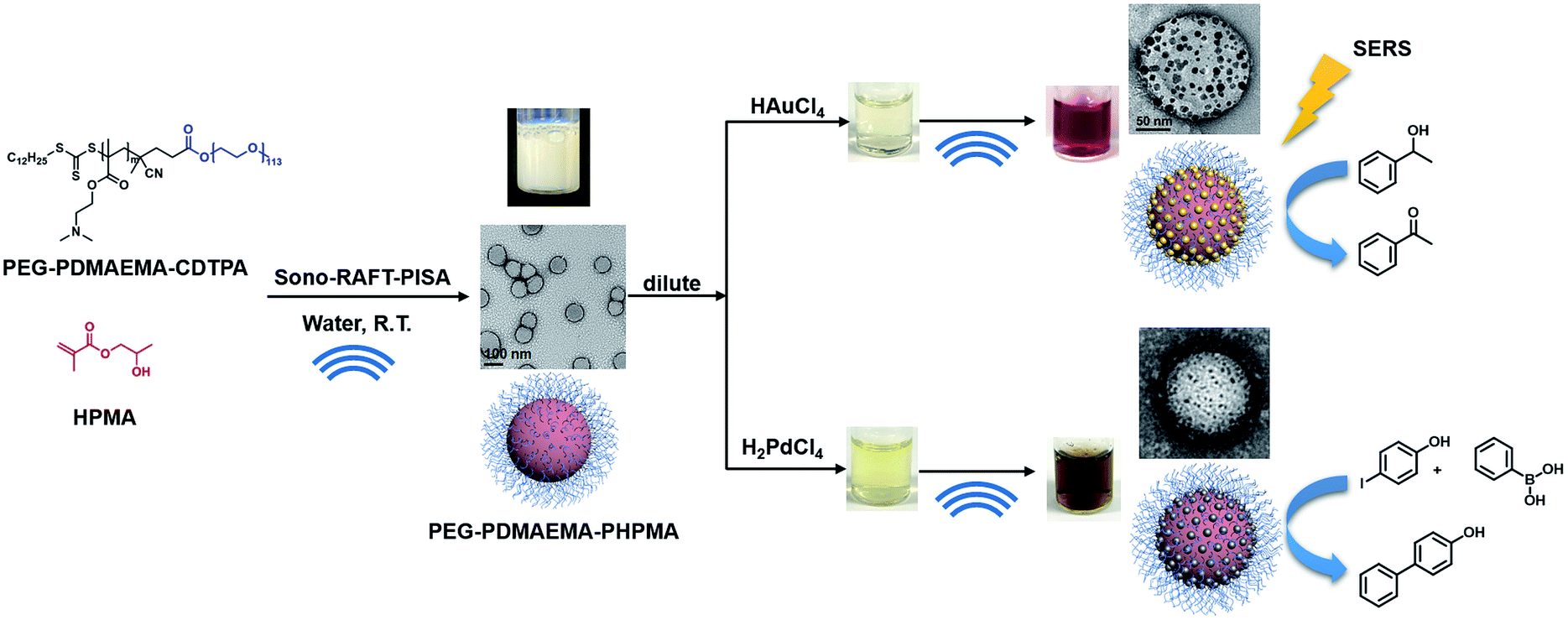
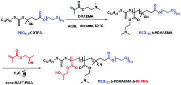
Meanwhile, with increasing interest in PISA, research devoted to initiation methods of PISA has become a new trend in recent years. Our previous study has demonstrated a room-temperature ultrasound-initiated PISA process without the addition of any thermo-/photo-initiators.21 The sonolysis of H2O and generation of H˙ and ˙OH to initiate RAFT polymerization in PISA provide a “green” alternative compared to the conventional thermo-/photo-process. Furthermore, ultrasound allows the preparation of gold colloids and palladium colloids without the addition of any reducing agents,22–26 as the H˙ generated during sonolysis can also reduce metal ions to form metal nanoparticles. However, to the best of our knowledge, there is no research yet devoted to the preparation of polymer–metal nanocomposites using ultrasound as both initiation and reducing sources. By combining the ability of ultrasound to initiate polymerization and produce metal nanoparticles, we demonstrate here not only a ‘green’ alternative without the addition of an initiator or reducing agent, but also a facile synthesis strategy for quick preparation of polymer–metal nanocomposites. Specifically, tertiary amine-containing polymeric nanoparticles were firstly synthesized by ultrasound-PISA (Scheme 1), and then they were used as the scaffold for in situ generation of metal nanoparticles by sonication. The formed polymer–Au nanocomposite with stepwise-grown AuNPs can be applied as a surface-enhanced Raman scattering (SERS) substrate for 4-aminothiophenol (4-ATP) detection. Meanwhile, the prepared polymer–Au and polymer–Pd nanocomposites were examined for catalytic applications and showed high catalytic efficiency in aerobic alcohol oxidation and the Suzuki–Miyaura cross-coupling reaction, respectively.
 |
| | Scheme 1 Synthesis of PEG113-b-PDMAEMA-b-PHPMA copolymers via the sono-RAFT-PISA process, and in situ formation of the Au and Pd nanocomposite by ultrasound. | |
Results and discussion
Synthesis of PEG113-b-PDMAEMA-b-PHPMA triblock copolymer nanoparticles
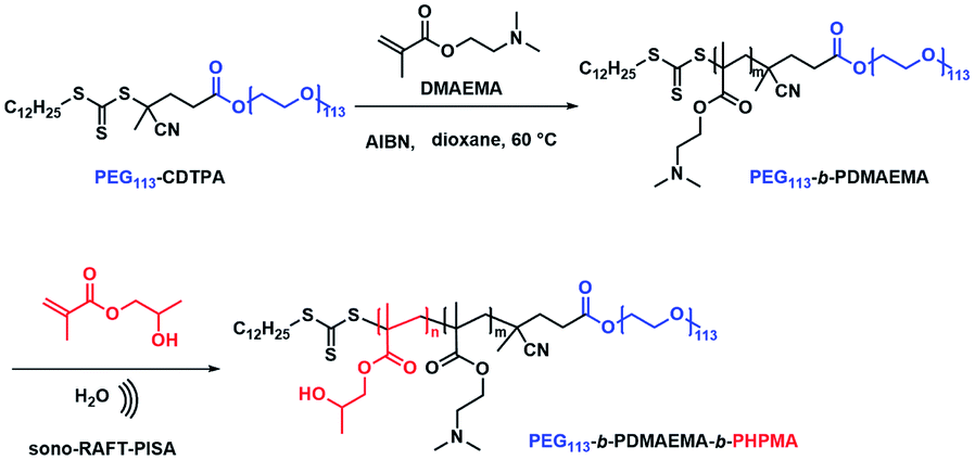
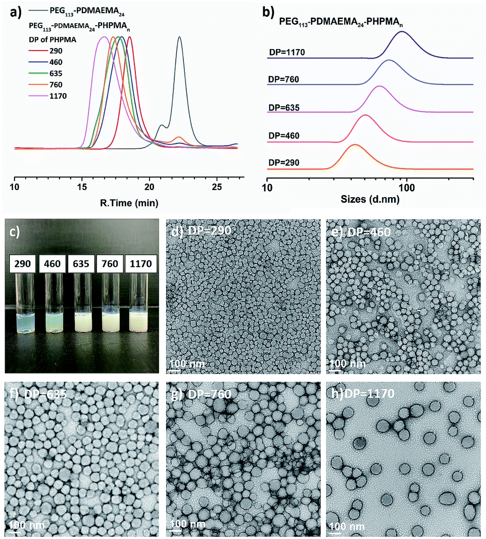
First, macro-chain transfer agent (macro-CTA) PEG113-CDTPA (Fig. S1†) was synthesized through Steglich esterification according to a previously published procedure.21 The PEG113-CDTPA was then chain extended with monomer DMAEMA in 1,4-dioxane (Scheme 2) via RAFT polymerization,27,28 yielding a diblock copolymer PEG113-b-PDMAEMA-CDTPA. To study the influence of the chain lengths of PDMAEMA on the formation of polymer nanoparticles and polymer–metal nanocomposites, three different batches were synthesized (Table S1†). The theoretical molecular weights (Mn,theo) of these hydrophilic block copolymers were matched with the molecular weight calculated via1H NMR spectra (Mn,NMR). Meanwhile, the GPC data (Table S1†) reveal that these block copolymers have low dispersities (Đ, 1.06–1.11), which indicates the well-controlled synthesis of the second blocks. It should be noted that the GPC traces of PEG113-b-PDMAEMA-CDTPA display bimodal distributions (Fig. S6†). The presence of side peak results from the purchased PEG113 because a similar side peak appears on the GPC trace of PEG113 (Fig. S7†). Meanwhile, it was also found that the molecular weights determined by GPC were higher than the theoretical molecular weights (Table S1†). The primary reason for this variation is the structural difference between PEG and the PMMA standards used for GPC calibration. In the next study, it was found that the shorter block of PDMAEMA (Table S1,† entry A, PEG113-b-PDMAEMA9-CDTPA) was not able to provide sufficient accessible tertiary amine sites for metal nanoparticles (Fig. S8a and b†). However, a longer block (Table S1,† entry C, PEG113-b-PDMAEMA46-CDTPA) provided enough tertiary amine but generated a long hydrophilic chain in the meantime, which required higher DP of HPMA to form core–shell micelles (Fig. S8c and d†). The medium-length PEG113-b-PDMAEMA24-CDTPA was found to meet both conditions. Therefore, the medium-length PEG113-b-PDMAEMA24-CDTPA was selected for the next studies.
 |
| | Scheme 2 Synthesis of PEG113-b-PDMAEMA and PEG113-b-PDMAEMA-b-PHPMA copolymers via the sono-RAFT-PISA process. | |
Next, PEG113-b-PDMAEMA24-CDTPA was used as the stabilizer block and HPMA as the monomer for sono-PISA at room temperature and 10% w/w solid content (Scheme 2). The PISA was conducted using the 990 kHz ultrasonic reactor, which can split water molecules to generate hydroxyl radicals and initiate polymerization. Different batches of PEG113-PDMAEMA24-PHPMAn with various PHPMA lengths were achieved by changing the targeting DP. As shown in Fig. 1c, with the increase of the DP of the PHPMA block, the cloudiness of the dispersions increased gradually, which indicates the formation of polymer nanoparticles. The dispersions synthesized via the PISA process were further analyzed by 1H NMR spectroscopy and GPC. The 1H NMR spectra (Fig. S9†) confirm that almost all monomers had converted to polymers in this PISA process. The GPC curves (Fig. 1a) exhibit clear shifting towards higher retention time with the increase of targeting DP. Meanwhile, it was noted that the Đ of these block copolymers increased from 1.21 at DP of 290 to 1.68 at DP of 1170 (Table 1). The broadening of the Đ could result from the impurities of PEG113 itself, and another possible reason is the branching of the PHPMA blocks caused by the side reaction of hydroxyl radicals with polymer chains. This phenomenon was observed in a previous study as well.21 Despite the relatively broad Đ, the subsequent characterization studies indicate that it did not adversely affect the formation of uniform polymer nanoparticles.
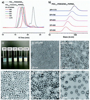 |
| | Fig. 1 (a) GPC traces and (b) DLS traces of PEG113-b-PDMAEMA24-b-PHPMAn (DP n = 290–1170) copolymers synthesized via sono-PISA. (c) Photographs and (d–h) TEM images of PEG113-b-PDMAEMA24-b-PHPMAn prepared via sono-PISA, the numbers represent the DP of PHPMA blocks (Table 1 entries 1–5 respectively). | |
Table 1 Characterization data of PEG113-b-PDMAEMA24-b-PHPMAn nanoparticles by sono-PISA
| Entry |
DP of HPMAa |
M
n,theo
(g mol−1) |
M
n,GPC (g mol−1) |
Đ
|
Z-Average (DLS) (nm) |
PDI (DLS) |
Diameter by TEMc (nm) |
|
DP was determined by the 1H NMR spectrum (Fig. S9).
M
n,theo = Mn,HPMA × conversion × 100 × ([HPMA]/[PEG113-b-PDMAEMA24-CDTPA]) + Mn,PEG113-b-PDMAEMA24-CDTPA.
Average diameter and standard deviation calculated by measuring 60 random particles.
|
| 1 |
290 |
51![[thin space (1/6-em)]](https://www.rsc.org/images/entities/char_2009.gif) 000 000 |
94200 |
1.21 |
56.0 ± 0.9 |
0.14 ± 0.01 |
36.6 ± 7.4 |
| 2 |
460 |
75500 |
143400 |
1.52 |
76.8 ± 0.8 |
0.14 ± 0.01 |
54.5 ± 8.3 |
| 3 |
635 |
100700 |
191300 |
1.55 |
88.0 ± 1.9 |
0.13 ± 0.02 |
74.8 ± 11.1 |
| 4 |
760 |
118700 |
225100 |
1.61 |
101.2 ± 1.8 |
0.08 ± 0.01 |
83.5 ± 12.6 |
| 5 |
1170 |
177900 |
341700 |
1.68 |
115.9 ± 1.2 |
0.10 ± 0.01 |
97.8 ± 15.2 |
The triblock copolymer dispersions were further analyzed by DLS and TEM. The DLS curves (Fig. 1b) show an apparent shifting of the particle sizes with the increase of PHPMA chain lengths; the average hydrodynamic size increased from 56.0 ± 0.9 nm at the DP of 290 to 115.9 ± 1.2 nm at the DP of 1170 (Table 1). Meanwhile, the polydispersity index (PDI) kept around 0.08–0.14, which indicated the narrow size distributions of synthesized nano-objects. The TEM images (Fig. 1d–h) reveal that the structures of the triblock copolymer nano-objects were spherical particles for all entries. No morphological transition to worms or vesicles was observed. Likewise, the TEM images revealed the particle size growth with the increase of the DP, and these images also confirmed the uniform size of these polymer nanoparticles. It should be noted that the particle sizes as measured from the TEM images were slightly smaller than those measured by DLS. This can be attributed to particles being in the dry state under TEM, and DLS could oversize the particles since the scattering from larger particles can increase the overall particle diameter.29 In this specific PISA process, no worm or vesicle but only spheres were formed even the DP had increased to 1170. This is due to the use of a relatively long stabilizer block (PEG113-b-PDMAEMA24-CDTPA), which could produce kinetically trapped spheres due to the steric repulsions between long stabilizing chains, preventing the fusion and reorganization of nanoparticles.30 The polymeric nanoparticles (Table 1, entry 5) with a relatively large size were then used for in situ nanocomposite formation with Au and Pd ions.
In situ synthesis of polymer–Au nanocomposites
The tertiary amine group in the PEG113-b-PDMAEMA24-b-PHPMAn can effectively bind with Au ions due to the chemisorption effect (Fig. 2).31–33 It was reported that the PDMAEMA block will be partially protonated with the addition of HAuCl4, and the remaining unprotonated tertiary amine groups can reduce the AuCl4− counterion to zero-valent Au in situ via the coordination–reduction mechanism without the addition of external reductants.34 McCormick et al. reported that when PDMAEMA:NaAuCl4 = 10:1, the reduction of AuCl4− to AuNPs was achieved via the coordination–reduction mechanism without the addition of external reductants.10 Zhao et al. also reported that Au3+ could be reduced by the hydroxyl group under alkaline conditions, thus achieving the green synthesis of AuNPs without any harsh reductive substance.35,36 The presence of hydroxyl groups in PHPMA and alkaline conditions from tertiary amine could potentially provide reducing conditions for Au3+. However, in our study, when the molar feed ratio of tertiary amine group (TA):HAuCl4 = 1:7, we did not observe self-reduction after 1 day at room temperature. This was also noticed in a previous report by Boyer and Davis.20 The slow self-reduction was because the majority of the TA was protonated with the addition of HAuCl4, and no additional TA was available to provide alkaline condition to reduce AuCl4−. Thus, an external reductant is required to form AuNPs, commonly, reducing agents, such as citrate and NaBH4 are added to reduce Au precursor ions. Nevertheless, ultrasound can provide a “green” alternative method to reduce metal ions to metal nanoparticles without the addition of any reducing agents. Since ultrasound at lower frequency has a higher rate of reduction,23 400 kHz ultrasound was selected for the formation of metal nanoparticles instead of the 990 kHz ultrasound used in the sono-PISA process. The sonolysis of H2O generates H˙ and ˙OH, the Au(III) is expected to be reduced by primary reducing species H˙ as shown in eqn (1) and (2).22,25 Alcohols such as 2-propanol can be added to act as a radical scavenger,22,25 which leads to additional reduction reaction (eqn (3)–(5)). These reactions combined could result in the formation of AuNPs. Meanwhile, a small quantity of poly(N-vinylpyrrolidone) (PVP) was added to improve the stability of nanocomposites as they can attach to the AuNPs, however, it could also compete with amino groups to form PVP-stabilized free AuNPs. Therefore, a low PVP concentration (0.2 mg mL−1) was selected after a few attempts.| | | H2O sonication → H˙ + ˙OH | (1) |
| | | AuCl4− + 3H˙ → Au0 + 4Cl− + 3H+ | (2) |
| | | H˙(˙OH) + Me2CHOH → Me2C˙(OH) + H2(H2O) | (3) |
| | | AuCl4− + 3Me2C˙(OH) → Au0 + 3Me2CO + 4Cl− + 3H+ | (4) |
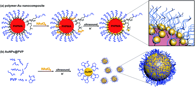 |
| | Fig. 2 Schematic illustration of the preparation of (a) polymer–Au nanocomposites and (b) PVP-stabilized AuNPs (AuNPs@PVP) via ultrasound sonication. | |
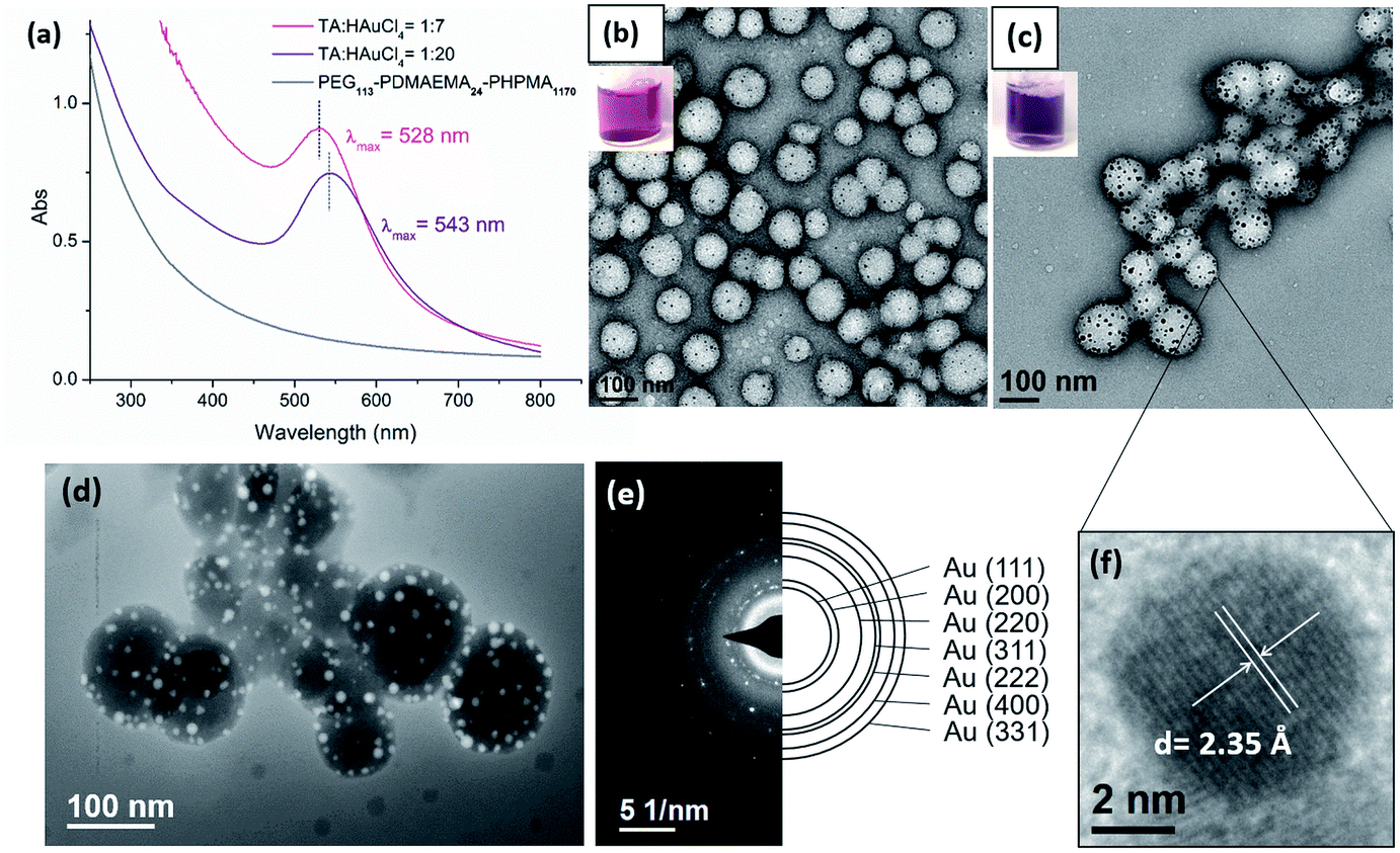
The immobilization of AuNPs on polymeric nanoparticles is confirmed by TEM, UV-Vis and high-angle annular dark-field imaging (HAADF). As shown in TEM images (Fig. 3b and c) of polymer–Au nanocomposites (Au@PEG113-b-PDMAEMA24-b-PHPMA1170) (TA:Au = 1:7 and 1:20), the spherical AuNPs were uniformly dispersed on the shell layer of the polymeric nanoparticles. Thermal gravimetric analysis (TGA) of purified nanocomposites was conducted to determine the Au mass loading on the polymer colloidal matrix. The determined mass loading of Au present in the nanocomposites is approximately equal to the theoretical Au content (Table S2, Fig. S10†). The size of AuNPs was dependent on the TA:Au ratio; the size of AuNPs was measured as 4–6 nm when TA:Au = 1:7, and 7–14 nm when TA:Au = 1:20. In UV-Vis analysis (Fig. 3a), the absorption spectra exhibited a surface plasmon resonance (SPR) band shifting from λmax = 529 nm to 542 nm when the TA:Au ratio changed from 1:7 to 1:20. This also reflects the size increment of AuNPs, which is in good agreement with the result measured by TEM. The formation of AuNPs was further confirmed by High-angle annular dark-field (HAADF) microscopy. HAADF is a STEM technique that is highly sensitive to variations of atomic number in the sample. For elements with a higher atomic number, the HAADF detector senses a stronger signal, causing them to appear brighter in the resulting image. Due to the high atomic number of Au compared to the polymer matrix, the AuNPs appeared brighter under HAADF (Fig. 3d). Meanwhile, this study evidently demonstrated the uniform distribution of AuNPs on the surface of the polymer nanoparticles. Fig. 3e shows the selected area electron diffraction (SAED) obtained from polymer–Au composites, which exhibits concentric rings with intermittent bright spots corresponding to (111), (200), (220), (311), (222), (400), and (331). The high-resolution TEM (HRTEM) image (Fig. 3f) of a gold nanoparticle shows that the lattice spacing for the (111) planes is measured to be 2.35 Å (measurement in Fig. S11a†). This reflects the polycrystalline and face-centered-cubic nature of the AuNP and provides direct evidence for the presence of AuNPs in the nanocomposite.
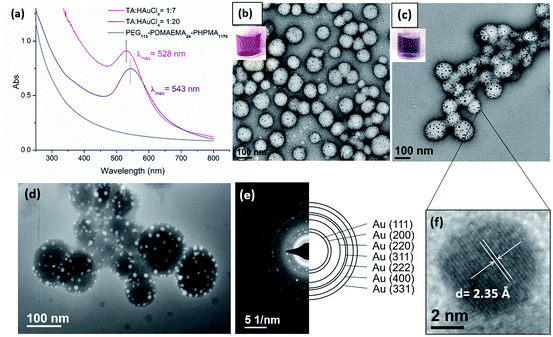 |
| | Fig. 3 (a) UV-Vis spectra of polymer–Au nanocomposites. Digital photos and TEM images of polymer–Au composites with (b) TA:Au = 1:7 and (c) TA:Au = 1:20. (d) STEM HAADF image and (e) SAED patterns of polymer–Au nanocomposites (TA:Au = 1:20). (f) High resolution TEM image of a gold nanoparticle. | |
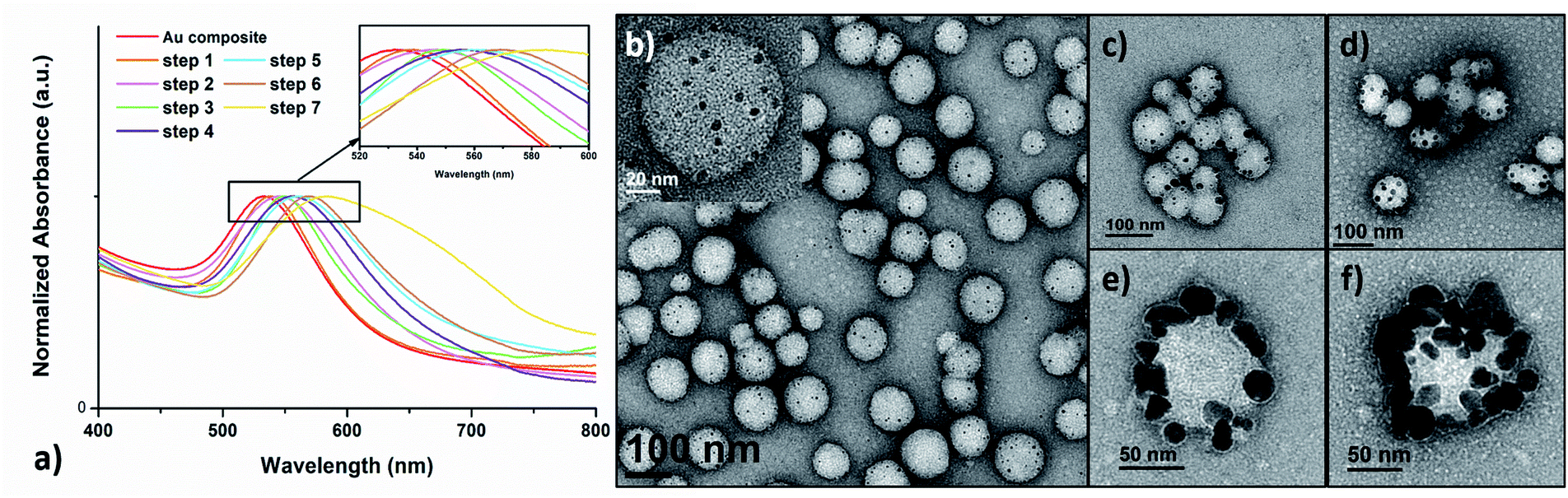
Next, the further size evolution of AuNPs was attempted by adjusting the molar ratio of TA:Au. However, by simply adjusting the initial TA:Au ratio from 1:7 or 1:20 to 1:100, the generated AuNPs were not uniform in size nor were they uniformly dispersed on the shell layer of the polymer nanoparticles (Fig. S12†). Thus, the originally prepared polymer–Au nanocomposite was used as seeds for further growth of AuNPs by stepwise growth methodology. Specifically, the initially prepared AuNPs in a lower TA:Au ratio (1:7) were used as seeds and a certain amount of HAuCl4 solution was added. In the next, reducing agent NH2OH was added to reduce the Au precursor and to form larger AuNPs. This step was repeated up to 7–9 times until the nanocomposites became unstable and formed precipitates. Meanwhile, UV-Vis spectroscopy and TEM were applied to monitor the growth of AuNPs. The UV-Vis spectra (Fig. 4a) showed that the λmax of the SPR band red-shifted about 4–6 nm per step and totally shifted up to 53 nm (from ∼530 nm to 583 nm) upon the growth of 7 steps. This result indicated that the size of the AuNPs increases with each growth step, because the SPR absorption of small AuNPs increases with their diameters.37 Furthermore, TEM analysis evidently revealed the AuNP size evolution; the size grew from ∼5 nm at the beginning to 20–30 nm at the final step (Fig. 4b–f). It was observed that the overall quantity of the AuNPs on each polymeric nanoparticle remained approximately constant, suggesting that the Au precursors were primarily consumed in the production of larger AuNPs and no new particle nucleation occurred.38,39
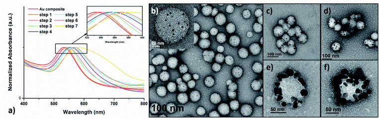 |
| | Fig. 4 (a) UV-Vis absorption spectra of plasmonic Au nanocomposites prepared by the stepwise growth. TEM images of the (b) initial polymer–Au nanocomposites and after (c) step 1, (d) step 2, (e) step 6 and (f) step 7. | |
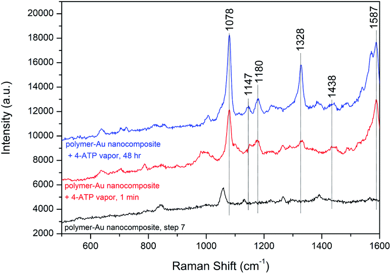
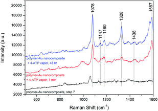
The densely clustered AuNPs on the surface of polymer–Au nanocomposites are expected to generate electromagnetic hot spots between the AuNPs, making the nanocomposite a potential surface-enhanced Raman scattering (SERS) substrate candidate for localized probe molecules. Therefore, the SERS effect of the polymer–Au nanocomposite after step 7 was further analyzed. We performed the SERS measurement on the drop-cast polymer–Au nanocomposite using 4-aminothiophenol (4-ATP) as the probe molecule. As shown in Fig. 5, two dominant peaks at 1078 and 1587 cm−1 were observed from the SERS spectra of the polymer–Au nanocomposite diffused by 4-ATP vapor for 1 min and 48 h. These correspond to the a1 vibrational modes of ν(C–S) and ν(C–C).40 The weaker enhancement of b2 modes at 1147, 1180, 1328 and 1438 cm−1 were also observed from the SERS spectra.40 This preliminary SERS measurement confirmed the application of the polymer–Au nanocomposite as a SERS substrate.
 |
| | Fig. 5 SERS spectra of 4-ATP vapor from the polymer–Au nanocomposite substrate and the original polymer–Au nanocomposite. | |
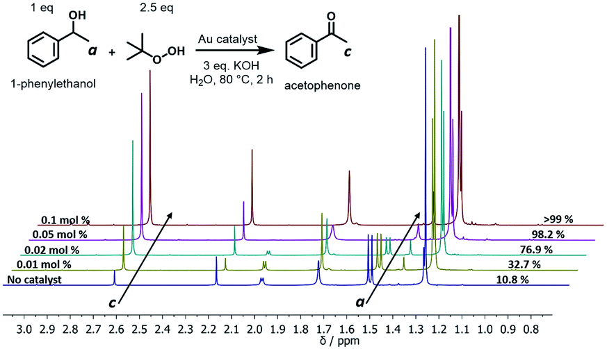
The oxidation of alcohols to aldehydes or ketones is a pivotal functional group transformation in organic chemistry. A prior study has found that AuNPs with a smaller size exhibit higher catalytic activity.41 Thus, the catalytic ability of the polymer–Au nanocomposite with smaller AuNPs (Au@PEG113-b-PDMAEMA24-b-PHPMA1170, TA:Au = 1:7) was testified through the oxidation reaction of 1-phenylethanol to acetophenone (Fig. 6). The reactions were conducted in water at 80 °C by fixing the reaction time to 2 hours and varying the catalyst quantities. The yield of acetophenone was calculated by the analysis of the 1H NMR spectra (Fig. 6). It was found that the doublet located at 1.52 ppm, which corresponds to the methyl group of 1-phenylethanol, gradually decreased in intensity with the increase of catalyst amount. Meanwhile, a new singlet located at 2.62 ppm, which corresponds to the methyl group of acetophenone, increased gradually in intensity. Without the presence of a catalyst, the reaction could only proceed with 10.8% yield (Table 2, entry 1), however, with the presence of 0.05 mol% polymer–Au nanocomposites the reaction proceeded with 98.2% yield in 2 hours (Table 2, entry 5). In addition, the catalytic efficiency of the polymer–Au nanocomposite was compared with that of PVP-stabilized AuNPs (Au@PVP) having the same average AuNP size (Fig. S16b†). Both catalysts could achieve full conversion within 2 h at 0.1 mol% of catalysts (Table 2, entries 2 and 3). However, by decreasing the catalyst concentration, Au@PVP exhibited lower catalytic efficiency compared to the polymer–Au nanocomposite. When the catalyst equivalent was 0.01 mol%, the yields were 21.0% for Au@PVP and 32.7% for the polymer–Au nanocomposite (Table 2, entries 8 and 9). The polymer–Au nanocomposite affords a higher turnover frequency (TOF) value of 1.64 × 10³ h−1, compared to 1.05 × 10³ h−1 of Au@PVP (calculated by the 0.01 mol% total Au atoms at 2 h). Generally, the catalytic efficiency of the polymer–Au nanocomposite is higher than that of AuNPs. The reason for this phenomenon is that PVP can dampen the catalytic activity by blocking active sites (e.g., edges, corners, and terraces) (Fig. 2b).9,42 For the polymer–Au nanocomposite (Fig. 2a), only a very small amount of PVP was added, and the AuNPs were embedded on the hydrophilic block of polymeric nano-spheres, leaving the relatively larger area of “naked” Au surface and thus more accessible active sites. The immobilization of AuNPs on the hydrophilic chains also allows good contact with reactants in the aqueous medium.
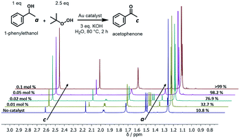 |
| | Fig. 6
1H NMR spectra of 1-phenylethanol oxidation (2.63 ppm: methyl group of acetophenone; 1.51 ppm: methyl group of 1-phenylethanol) (the full spectrum and the NMR yield calculation equation are available in Fig. S13†). | |
Table 2 Aerial oxidation reaction of 1-phenylethanol to acetophenone using the Au catalyst
| Entry |
Catalyst |
Catalyst eq.a (mol%) |
NMR yield (%) |
|
Catalyst eq. (mol%) = [catalyst]/[1-phenylethanol] × 100%.
|
| 1 |
None |
— |
10.8 |
| 2 |
Au@PVP |
0.1 |
>99 |
| 3 |
Polymer–Au nanocomposite |
0.1 |
>99 |
| 4 |
Au@PVP |
0.05 |
92.6 |
| 5 |
Polymer–Au nanocomposite |
0.05 |
98.2 |
| 6 |
Au@PVP |
0.02 |
71.4 |
| 7 |
Polymer–Au nanocomposite |
0.02 |
76.9 |
| 8 |
Au@PVP |
0.01 |
21.0 |
| 9 |
Polymer–Au nanocomposite |
0.01 |
32.7 |
Another significant aspect of the nanocomposite catalyst is the reusability. Therefore, the performance of the reused nanocomposite was also studied, and the data are presented in Fig. S17,† the polymer–Au composite maintained its well stability and dispersity after separation. In addition, the composite was reused without a notable loss of catalytic activity with near full conversion in the first four batches and good yield in the fifth batch (Fig. S17 and S18†).
In situ synthesis of polymer–Pd nanocomposites
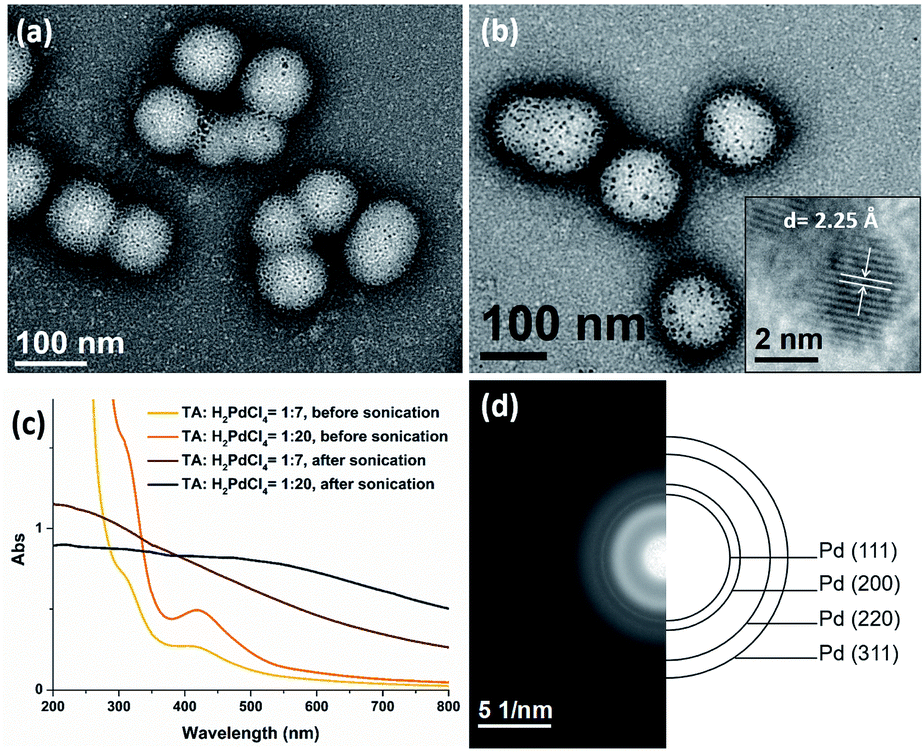
The presence of TA groups in the shell of polymer nanoparticles also allows the immobilization of Pd nanoparticles (PdNPs) through the coordination between the amino groups with Pd ions and subsequent reduction by ultrasound generated reducing species. The successful immobilization of PdNPs on the polymer matrix was confirmed by TEM, UV-Vis spectroscopy and SAED. Specifically, the TEM images (Fig. 7a and b) reveal that PdNPs with a size of 1–4 nm (TA:Pd: tertiary amine = 1:7) and 3–5 nm (TA:Pd: tertiary amine = 1:20) were uniformly dispersed on the shell layer of the polymeric nanoparticles. In addition, the UV-Vis spectra (Fig. 7c) show the absorption band at 420 nm corresponding to Pd2+ ions disappeared after sonication, indicating that Pd(II) has been completely reduced to Pd(0). Furthermore, the HRTEM image (Fig. 7b inset) of a PdNP shows that the lattice spacing for the (111) planes is measured to be 2.25 Å (measurement in Fig. S11b†). The SAED pattern (Fig. 7d) of the nanocomposites exhibits concentric rings, corresponding to the (111), (200), (220), and (311) crystal planes of the face-centered-cubic structure of Pd, which further demonstrate the presence of PdNPs.
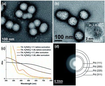 |
| | Fig. 7 TEM images of Pd@PEG113-b-PDMAEMA24-b-PHPMA1170 nanocomposites with a TA:Pd ratio of (a) 1:7 and (b) 1:20. (c) UV-vis spectra of the palladium nanocomposite before and after sonication. (d) The selected area electron diffraction pattern of the nanocomposites. | |
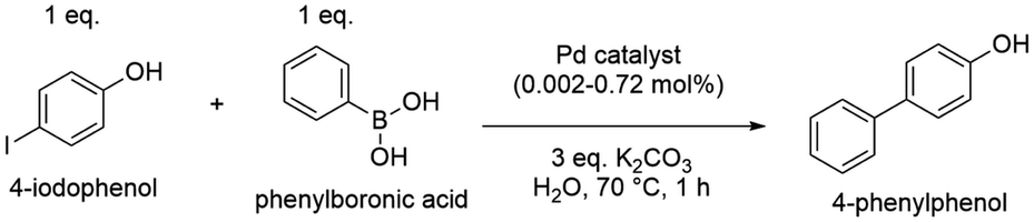
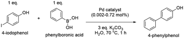
Pd(0) catalysts have been broadly utilized in the Suzuki–Miyaura cross-coupling reaction, which is the C–C bond formation between aryl halides and aryl boronic acids, and is a powerful tool in organic syntheses.43 Recently, many studies have synthesized new types of Pd catalysts, including Pd with different ligands, Pd immobilized on MOFs and other new matrices, which had good catalytic efficiency.44–47 Herein, the polymer–Pd nanocomposite (Pd@PEG113-b-PDMAEMA24-b-PHPMA1170, TA:Pd = 1:7) catalyzed Suzuki–Miyaura cross-coupling of 4-iodophenol and phenylboronic acid was examined and compared with commercial palladium on activated carbon (Pd/C) and Pd@PVP (Fig. S16d†). In the absence of any Pd catalysts, the coupling reaction could only proceed with 8.5% yield (Table 3, entry 1) in 1 hour. All Pd catalysts were found to exhibit excellent efficiency, with almost complete conversions achieved at catalyst concentrations above 0.18 mol% (Table 3, entries 2–4). Because of the high efficiency of Pd catalysts, the concentration of catalysts was reduced step by step to compare their catalytic efficiency at a lower dosage. As shown in Table 3, the efficiency of Pd@PVP and polymer–Pd nanocomposites remained at excellent levels, achieving a nearly complete conversion even when the concentration was reduced to 0.04 mol% (Table 3, entries 6, 7, 9 and 10). In contrast, the yield decreased to 44.8% for Pd/C at the catalyst concentration of 0.09 mol% (Table 3, entry 5), and it further reduced to 12.5% (Table 3, entry 8), which is close to the control group without any Pd catalyst, at the catalyst concentration of 0.04 mol%.
Table 3 Summary of the Suzuki–Miyaura cross coupling reaction using different types of Pd catalysts
|
|
| Entry |
Catalyst |
Catalyst eq.a (mol%) |
NMR yieldb (%) |
|
Catalyst eq. (mol%) = [catalyst]/[4-iodophenol] × 100%.
Yield was calculated by comparing the NMR spectrum of reaction, and the detailed calculation equation is listed in Fig. S15.
|
| 1 |
None |
— |
8.5 |
| 2 |
Pd/C |
0.18–0.72 |
>99 |
| 3 |
Pd@PVP |
0.18–0.72 |
>99 |
| 4 |
Polymer–Pd nanocomposite |
0.18–0.72 |
>99 |
| 5 |
Pd/C |
0.09 |
44.8 |
| 6 |
Pd@PVP |
0.09 |
>99 |
| 7 |
Polymer–Pd nanocomposite |
0.09 |
>99 |
| 8 |
Pd/C |
0.04 |
12.5 |
| 9 |
Pd@PVP |
0.04 |
>99 |
| 10 |
Polymer–Pd nanocomposite |
0.04 |
>99 |
| 11 |
Pd@PVP |
0.02 |
96.8 |
| 12 |
Polymer–Pd nanocomposite |
0.02 |
97.4 |
| 13 |
Pd@PVP |
0.01 |
92.6 |
| 14 |
Polymer–Pd nanocomposite |
0.01 |
93.8 |
| 15 |
Pd@PVP |
0.004 (40 ppm) |
51.5 |
| 16 |
Polymer–Pd nanocomposite |
0.004 (40 ppm) |
65.8 |
| 17 |
Pd@PVP |
0.002 (20 ppm) |
21.5 |
| 18 |
Polymer–Pd nanocomposite |
0.002 (20 ppm) |
33.6 |
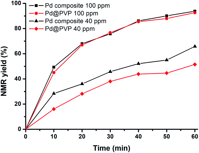
Polymer–Pd nanocomposites and Pd@PVP could achieve high conversions even at catalyst concentration as low as 0.01 mol% (100 ppm, Table 3, entries 13 and 14). Therefore, to compare the catalytic efficiency of polymer–Pd nanocomposites and Pd@PVP at extremely low concentrations, the reactions were conducted with 100 ppm and 40 ppm of corresponding catalysts, and the kinetics were monitored by NMR analysis with periodic sampling. As shown in Fig. 8, the efficiency performances of both catalysts were very close at the concentration of 100 ppm. Nevertheless, the polymer–Pd nanocomposite was more efficient than Pd@PVP at the concentration of 40 ppm, and it has a higher TOF value of 4.3 × 10⁴ h−1, compared to 2.5 × 10⁴ h−1 of Pd@PVP (calculated by the 0.004 mol% total Pd atoms at 10 min). Notably, the polymer–Pd nanocomposite still achieved a yield of 33.6% within 1 h at 20 ppm (Table 3, entry 18) compared to the 21.5% yield of Pd@PVP under the same conditions (Table 3, entry 17). Overall, the catalytic efficiency of the immobilized Pd nanocatalyst was verified to be higher than those of Pd/C and Pd@PVP in this 4-iodophenol and phenylboronic acid Suzuki–Miyaura cross-coupling reaction. This can be explained by the same rationales as discussed for polymer–Au nanocomposites. On the other hand, the catalytic activity of polymer–Pd nanocomposites gradually decreased after several reuse tests (Fig. S19 and S20†). The yield decreased from 98.8 to 82.1% after 5 times, however, the yields are still within the acceptable range for practical application.
 |
| | Fig. 8 Time-dependent NMR yield of 4-phenylphenol in the Suzuki–Miyaura coupling catalyzed by polymer–Pd nanocomposites and Pd@PVP. | |
Conclusions
It was demonstrated that polymer–metal nanocomposites could be prepared by utilizing ultrasound as the initiation and reducing source for the synthesis of polymer and metal nanoparticles, respectively. The use of sono-PISA provides an effective in situ self-assembly strategy for the scalable preparation of copolymer nano-spheres PEG113-b-PDMAEMA24-b-PHPMAn. It was also shown that the sizes of the polymeric nano-spheres can be easily modified by increasing the DP of the PHPMA block. In addition, using ultrasound as the reducing source, it is possible to prepare polymer–Au and polymer–Pd nanocomposites with AuNPs and PdNPs being immobilized on the hydrophilic shell of the polymer matrix. It was found that the size of metal nanoparticles is closely related to the ratio of tertiary amine groups in the polymer matrix to metal atoms. These polymer–metal nanocomposite materials are particularly attractive as nano-catalysts, and the catalytic applications of both polymer–Au and polymer–Pd nanocomposites were demonstrated for the aerobic oxidation of alcohol and Suzuki–Miyaura cross-coupling reactions, respectively. Meanwhile, these metal nanocomposites exhibit superior catalytic efficiency to PVP-stabilized metal nanoparticles or commercially available Pd/C. Furthermore, it was also demonstrated that the sizes of AuNPs on the polymer matrix could be further grown incrementally to afford potential applications such as SERS substrates. Overall, this study should open many new prospects for the field of polymer–metal nanocomposites due to the “green” nature of sonochemistry and scalable feature of the PISA process. Future work will involve the in situ formation of metal nanoparticles on the stabilizing macro-RAFT agent by ultrasound followed by the sono-PISA process, or even a “one-pot” synthesis of polymer–metal composites by forming metal nanoparticles and sono-PISA in the same reaction flask.
Conflicts of interest
There are no conflicts to declare.
Acknowledgements
J. W. thanks Monash University for the MGS and MITS scholarships. The authors greatly acknowledge the Monash Centre for Electron Microscopy (MCEM) for the permission to use their facilities. The authors wish to thank Dr Boon M. Teo of Monash University, School of Chemistry for her advice and discussion during this research. The authors also thank Dr Tim Williams for the HRTEM imaging, Dr Xiya Fang for the STEM test and Dr Qianqian Shi for the Raman measurement.
Notes and references
- O. S. Muddineti, B. Ghosh and S. Biswas, Int. J. Pharm., 2015, 484, 252–267 CrossRef CAS PubMed.
- M. Han, X. Gao, J. Z. Su and S. Nie, Nat. Biotechnol., 2001, 19, 631–635 CrossRef CAS PubMed.
- I. V. Kityk, J. Ebothé, I. Fuks-Janczarek, A. A. Umar, K. Kobayashi, M. Oyama and B. Sahraoui, Nanotechnology, 2005, 16, 1687–1692 CrossRef CAS.
- Y. Liu, B. Fan, Q. Shi, D. Dong, S. Gong, B. Zhu, R. Fu, S. H. Thang and W. Cheng, ACS Nano, 2019, 13, 6760–6769 CrossRef CAS PubMed.
- D. M. Vriezema, M. Comellas Aragonès, J. A. A. W. Elemans, J. J. L. M. Cornelissen, A. E. Rowan and R. J. M. Nolte, Chem. Rev., 2005, 105, 1445–1490 CrossRef CAS PubMed.
- P. Shi, C. Gao, X. He, P. Sun and W. Zhang, Macromolecules, 2015, 48, 1380–1389 CrossRef CAS.
- S. Ogasawara and S. Kato, J. Am. Chem. Soc., 2010, 132, 4608–4613 CrossRef CAS PubMed.
- P. N. Eyimegwu, J. A. Lartey and J.-H. Kim, ACS Appl. Nano Mater., 2019, 2, 6057–6066 CrossRef CAS.
- W. Jang, J. Yun, L. Ludwig, S. G. Jang, J. Y. Bae, H. Byun and J.-H. Kim, Front. Chem., 2020, 8, 834 CrossRef CAS PubMed.
- Y. Li, A. E. Smith, B. S. Lokitz and C. L. McCormick, Macromolecules, 2007, 40, 8524–8526 CrossRef CAS.
- P. Lim Soo and A. Eisenberg, J. Polym. Sci., Part B: Polym. Phys., 2004, 42, 923–938 CrossRef.
- Z. Deng and S. Liu, Polymer, 2020, 207, 122914 CrossRef CAS.
- B. Fan, R. E. Yardley, J. F. Trant, A. Borecki and E. R. Gillies, Polym. Chem., 2018, 9, 2601–2610 RSC.
- B. Fan, J. F. Trant, G. Hemery, O. Sandre and E. R. Gillies, Chem. Commun., 2017, 53, 12068–12071 RSC.
- J. F. Trant, N. Jain, D. M. Mazzuca, J. T. McIntosh, B. Fan, S. M. Haeryfar, S. Lecommandoux and E. R. Gillies, Nanoscale, 2016, 8, 17694–17704 RSC.
- B. Fan, J. Wan, J. Zhai, X. Chen and S. H. Thang, ACS Nano, 2021, 15, 4688–4698 CrossRef CAS PubMed.
- B. Fan, Y. Liu, J. Wan, S. Crawford and S. H. Thang, ACS Mater. Lett., 2020, 2, 492–498 CrossRef CAS.
- Y. Zhang, P. Filipczak, G. He, G. Nowaczyk, L. Witczak, W. Raj, M. Kozanecki, K. Matyjaszewski and J. Pietrasik, Polymer, 2017, 129, 144–150 CrossRef CAS.
- Y. Zhang, Z. Wang, K. Matyjaszewski and J. Pietrasik, Eur. Polym. J., 2019, 110, 49–55 CrossRef CAS.
- R. Bleach, B. Karagoz, S. M. Prakash, T. P. Davis and C. Boyer, ACS Macro Lett., 2014, 3, 591–596 CrossRef CAS.
- J. Wan, B. Fan, Y. Liu, T. Hsia, K. Qin, T. Junkers, B. M. Teo and S. H. Thang, Polym. Chem., 2020, 11, 3564–3572 RSC.
- R. A. Caruso, M. Ashokkumar and F. Grieser, Langmuir, 2002, 18, 7831–7836 CrossRef CAS.
- K. Okitsu, M. Ashokkumar and F. Grieser, J. Phys. Chem. B, 2005, 109, 20673–20675 CrossRef CAS PubMed.
- K. Okitsu, A. Yue, S. Tanabe, H. Matsumoto and Y. Yobiko, Langmuir, 2001, 17, 7717–7720 CrossRef CAS.
- S. A. Yeung, R. Hobson, S. Biggs and F. Grieser, J. Chem. Soc., Chem. Commun., 1993, 4, 378–379 RSC.
- Y. Mizukoshi, K. Okitsu, Y. Maeda, T. A. Yamamoto, R. Oshima and Y. Nagata, J. Phys. Chem. B, 1997, 101, 7033–7037 CrossRef CAS.
- B. Fan, J. Wan, A. McKay, Z. Qu and S. H. Thang, Polym. Chem., 2020, 11, 5649–5658 RSC.
- J. Chiefari, Y. K. Chong, F. Ercole, J. Krstina, J. Jeffery, T. P. T. Le, R. T. A. Mayadunne, G. F. Meijs, C. L. Moad, G. Moad, E. Rizzardo and S. H. Thang, Macromolecules, 1998, 31, 5559–5562 CrossRef CAS.
- B. Fan and E. R. Gillies, Mol. Pharmaceutics, 2017, 14, 2548–2559 CrossRef CAS PubMed.
- N. J. W. Penfold, J. Yeow, C. Boyer and S. P. Armes, ACS Macro Lett., 2019, 8, 1029–1054 CrossRef CAS.
- J. D. S. Newman and G. J. Blanchard, Langmuir, 2006, 22, 5882–5887 CrossRef CAS PubMed.
- J. Hu, G. Zhang, Z. Ge and S. Liu, Prog. Polym. Sci., 2014, 39, 1096–1143 CrossRef CAS.
- S. Luo, J. Xu, Y. Zhang, S. Liu and C. Wu, J. Phys. Chem. B, 2005, 109, 22159–22166 CrossRef CAS PubMed.
- J.-J. Yuan, A. Schmid, S. P. Armes and A. L. Lewis, Langmuir, 2006, 22, 11022–11027 CrossRef CAS PubMed.
- G. Zhao, X. Ran, X. Zhou, X. Tan, H. Lei, X. Xie, L. Yang and G. Du, ACS Sustainable Chem. Eng., 2018, 6, 3938–3947 CrossRef CAS.
- X. Tan, Y. Fan, S. Wang, Y. Wu, W. Shi, T. Huang and G. Zhao, Electrochim. Acta, 2020, 335, 135706 CrossRef CAS.
- W. Haiss, N. T. K. Thanh, J. Aveyard and D. G. Fernig, Anal. Chem., 2007, 79, 4215–4221 CrossRef CAS PubMed.
- K. R. Brown and M. J. Natan, Langmuir, 1998, 14, 726–728 CrossRef CAS.
- K. R. Brown, D. G. Walter and M. J. Natan, Chem. Mater., 2000, 12, 306–313 CrossRef CAS.
- K. J. Si, D. Sikdar, L. W. Yap, J. K. K. Foo, P. Guo, Q. Shi, M. Premaratne and W. Cheng, Adv. Opt. Mater., 2015, 3, 1710–1717 CrossRef CAS.
- H. Tsunoyama, H. Sakurai, Y. Negishi and T. Tsukuda, J. Am. Chem. Soc., 2005, 127, 9374–9375 CrossRef CAS PubMed.
- K. M. Koczkur, S. Mourdikoudis, L. Polavarapu and S. E. Skrabalak, Dalton Trans., 2015, 44, 17883–17905 RSC.
- S. E. Hooshmand, B. Heidari, R. Sedghi and R. S. Varma, Green Chem., 2019, 21, 381–405 RSC.
- R. Martin and S. L. Buchwald, Acc. Chem. Res., 2008, 41, 1461–1473 CrossRef CAS PubMed.
- B. Yuan, Y. Pan, Y. Li, B. Yin and H. Jiang, Angew. Chem., Int. Ed., 2010, 49, 4054–4058 CrossRef CAS PubMed.
- W. Dong, L. Zhang, C. Wang, C. Feng, N. Shang, S. Gao and C. Wang, RSC Adv., 2016, 6, 37118–37123 RSC.
- M. W. Easson, J. H. Jordan, J. M. Bland, D. J. Hinchliffe and B. D. Condon, ACS Appl. Nano Mater., 2020, 3, 6304–6309 CrossRef CAS.
Footnote |
| † Electronic supplementary information (ESI) available: Experimental details, 1H NMR, 13C NMR spectra and MS spectra of RAFT agents and polymers, GPC curves and additional TEM images. See DOI: 10.1039/d1na00120e |
|
| This journal is © The Royal Society of Chemistry 2021 |
Click here to see how this site uses Cookies. View our privacy policy here. 
 Open Access Article
 This Open Access Article is licensed under a Creative Commons Attribution-Non Commercial 3.0 Unported Licence
 ,
Bo
Fan
,
Bo
Fan