
 Open Access Article
 This Open Access Article is licensed under a Creative Commons Attribution-Non Commercial 3.0 Unported Licence
Fabrication of a porous NiFeP/Ni electrode for highly efficient hydrazine oxidation boosted H2 evolution†
Honglei
Wang
and
Shengyang
Tao
 *
*
Department of Chemistry, School of Chemical Engineering, Dalian University of Technology, Dalian 116024, China. E-mail: taosy@dlut.edu.cn
First published on 2nd March 2021
Abstract
Rational optimization of the surface electronic states and physical structures of non-noble metal nanomaterials is essential to improve their electrocatalytic performance. Herein, we report a facile dual-regulation strategy to fabricate NiFeP/Ni (P-NiFeP/Ni) porous nanoflowers, which involves Fe-doping and creating pores on nanosheets. The as-prepared P-NiFeP/Ni has a hierarchically porous surface, which exposes more electrochemically active sites and dramatically enhances the electron transfer rate. Thus, it exhibits excellent catalytic activity in both anodic hydrazine oxidation reaction (HzOR) and cathodic hydrogen evolution reaction (HER). Interestingly, the coupled electrolysis cell only offers a potential of 0.162 V at 10 mA cm−2 to enable HzOR boosted H2 evolution, highlighting an energy-saving hydrogen evolution strategy.
Introduction
With the continuous growth of energy consumption and the increasingly severe environmental problems, hydrogen energy, renewable clean energy, has been widely developed and utilized.1–3 Electrolysis of water is considered one of the most suitable green and efficient hydrogen evolution technologies.4–8 However, the oxygen evolution reaction (OER) is considered to be a slow oxidation process, which leads to significant energy consumption and seriously hinders the up-scale application.9–11 Therefore, it is imperative to choose a candidate that more readily facilitates oxidation reaction than the OER to reduce energy wastage. Among many alternative OERs (oxidation of methanol,12 ethanol,13 benzyl alcohol,14 pentahydroxymethyl furfural (HMF),15 urea,16 and hydrazine,17,18etc.), the hydrazine oxidation reaction (HzOR) possesses an ultra-low theoretical overpotential, gives a single product, and provides safe environmental protection. Recently, substantial efforts have aimed at efficiently reducing electrolytic voltage via coupling the HzOR with the HER,19,20 while it is still an urgent problem to develop low-cost, plentiful, active, and durable HzOR catalysts.Transition metal phosphides are attractive candidates for HzOR electrocatalysts because of their appealing conductivity, excellent activity, chemical stability, facile synthesis, and inexpensive starting materials.21,22 As is well known, the regulation of electronic states on the surface of materials is one of the critical factors to affect the activity of catalysts.23–27 A variety of tuning strategies such as heteroatom doping,28,29 heterojunction formation,30 and nanostructure design31 have been developed to improve the catalytic performance and tune the electronic states of catalysts. Among them, tuning the surface electronic states of materials by heteroatom doping has attracted much attention since doping can improve the redistribution of electrons, and affect the adsorption of reactants and the desorption of products.32 Strikingly, the synergism of heteroatoms is also conducive to further improving the material stability.33 Therefore, we conclude that transition metal phosphates optimized by heteroatom doping can improve the electrochemical reaction activity.
The porous structure of materials can provide a larger specific surface area, expose more active sites, achieve better contact with the electrolyte, and shorten the diffusion path of ions and electrons.34,35 In recent years, physical structure modification methods have been explored to produce efficient electrocatalytic materials, such as ball milling,36 bulk material exfoliation,37 surface pore-creating,38etc. The ball milling and bulk material exfoliation processes often require high-quality crystals, and they are complex, time-consuming, and high-cost processes. Meanwhile, the crystal structure of materials would be seriously destroyed due to the role of mechanical force, resulting in unfavorable defects and increased recombination rate.39 In contrast, pores created on the material surface by merely adjusting the reaction conditions show excellent promise for the production of high activity catalytic materials but rarely demonstrate the possibility of double regulation of the surface electronic states and physical structures of catalysts.
Herein, a simple dual-regulation strategy was proposed for the production of porous NiFeP/Ni (P-NiFeP/Ni), obtained via element doping and phosphorus source content adjustment. This dual-regulation not only regulates the surface electronic states of the catalyst by doping with Fe, but also improves the electrochemical surface area (ECSA) of the catalyst by adjusting the P content. The resulting P-NiFeP/Ni electrode has a specific double-layer capacitance of up to 53.6 mF cm−2, high electrical conductivity, and nanosheet morphology with well-distributed primarily 20 to 200 nm-width pores. P-NiFeP/Ni shows that a remarkably improved electrocatalytic hydrogen evolution and hydrazine oxidation activity can be obtained, which is higher than that of the non-porous NiFeP/Ni and Ni2P/Ni. We further show that the coupling electrode only offers 0.162 V at 10 mA cm−2 electrolysis potential to enable the HzOR, which provides a novel approach to realize the double adjustment of surface electronic states and physical structure for HzOR boosted energy-saving hydrogen evolution.
Results and discussion
A facile dual-regulation strategy is employed to fabricate the hierarchically porous nanoflowers of P-NiFeP/Ni (Scheme 1). Briefly, a moderate hydrothermal method was first implemented to obtain Ni(OH)2·0.75H2O nanoflowers (Fig. S1a†), and then the precursor Ni0.75Fe0.25(CO3)0.125(OH)2·0.38H2O (Pre-NiFe/Ni) was prepared by a Fe atom doping strategy (Fig. S1b†). As shown in Fig. S2,† doping of the Fe atom reduced the size of sheets, which formed the nanoflower, and made the surface morphology of the material more porous than that without Fe. This indicates that the surface morphology of materials can be regulated via doping elements.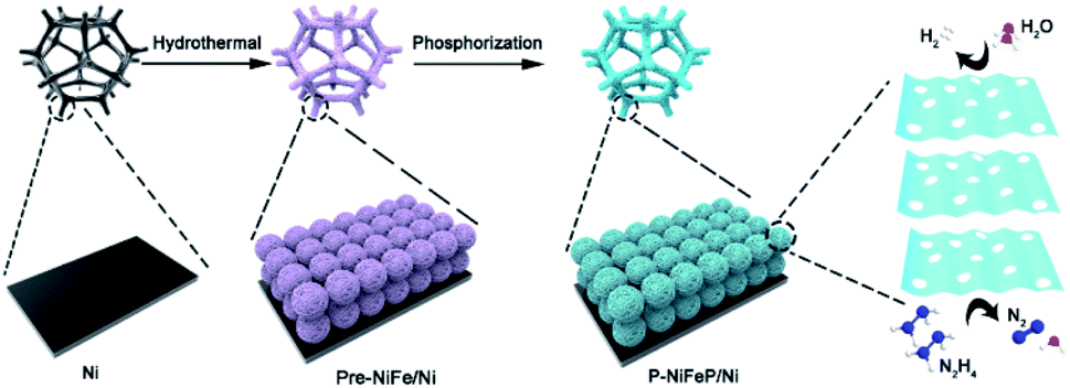 | ||
| Scheme 1 Schematic diagram of the fabrication and catalytic reaction of P-NiFePNi. | ||
Subsequently, the gas–solid conversion and phosphorus source content regulation process, which drove both the phosphorization and pore-creation synchronously, were adopted to realize the precursor transformation into the corresponding phosphorization species. The flower-like P-NiFeP/Ni composed of nanosheets could be obtained via low-temperature phosphorization (Fig. 1a and b). Interestingly, there are many nanopores on the surface of these nanosheets via controlling the appropriate content of the phosphorus source. This phenomenon may be due to the release of water vapor by the precursor and volume shrinkage in thermal condensation, which will form many pores on the nanosheets.39 During the thermal phosphating process, a large number of gas products (PH3) were produced, which can tune the original pore structure of nanosheets during the gas–solid reaction.40 The hierarchically porous structure of the nanoflowers can enlarge the accessibility of the surface and enable excellent contact with reactants, thus enhancing the catalytic activity. Fig. S3† confirms that the pore size increased with the increase of phosphorus source content, while an excessive phosphorus source would lead to the stacking of nanosheets. Therefore, the pores formed on the nanosheets were controlled by the content of the phosphorus source. Energy-dispersive X-ray spectroscopy (EDS) element mapping indicates the homogeneous distribution of Ni, Fe, P, and O elements in P-NiFeP/Ni (Fig. 1c).
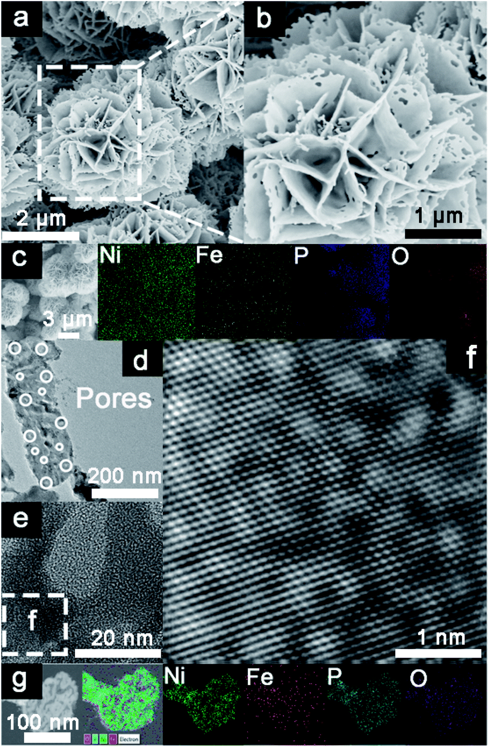 | ||
| Fig. 1 Scanning electron microscopy (SEM) images of (a and b) P-NiFeP/Ni. (c) The elemental mapping images of P-NiFeP/Ni. (d) The TEM and (e) HRTEM images of P-NiFeP/Ni. (f) The magnified image from the white square inserted in (e). (g) The TEM elemental mapping images of P-NiFeP/Ni. | ||
Transmission electron microscopy (TEM) and high-resolution TEM (HRTEM) pictures (Fig. 1d and e) indicate that the pore size is 20–200 nm wide and (Fig. 1f) there are clear lattice fringes, which confirm the formation of as-obtained P-NiFeP/Ni. The TEM elemental map suggests that the Ni, Fe, P, and O elements are distributed in the as-obtained P-NiFeP/Ni (Fig. 1g), further supporting the successful synthesis of P-NiFeP/Ni. Meanwhile, the NiFeP/Ni and Ni2P/Ni samples were prepared for comparison (Fig. S4†). Fig. 2a shows the X-ray power diffraction (XRD) patterns of P-NiFeP/Ni. Three strong diffraction peaks (≈45°, 52°, 76°) are attributed to the typical metallic nickel from the nickel foam in the material. Besides the diffraction peak of the metallic nickel, most of the residual peaks in the sample are well indexed to the Ni2P (JCPDS no. 03-0953). Meanwhile, a small part of Ni3Fe4(PO4)6 comes from surface oxidation of the material.
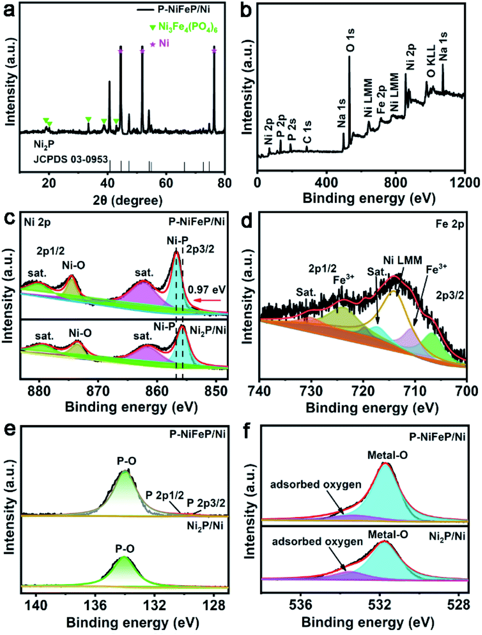 | ||
| Fig. 2 (a) XRD patterns of bare Ni foam (in pink star), Ni3Fe4(PO4)6 (in green star) and P-NiFeP/Ni (in black). (b) The full spectrum XPS of P-NiFeP/Ni. (c) The high-resolution XPS spectra of Ni 2p for P-NiFeP/Ni and Ni2P/Ni. (d) The XPS spectra of Fe 2p for P-NiFeP/Ni. The high-resolution XPS spectra of P-NiFeP/Ni and Ni2P/Ni: (e) P 2p region and (f) O 1s region. | ||
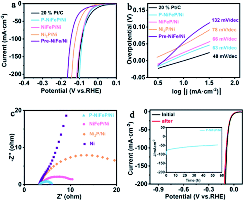
X-ray photoelectron spectroscopy (XPS) was conducted to analyze the electronic structure and element chemical valence state of P-NiFeP/Ni. The XPS full survey spectrum of P-NiFeP/Ni indicates that the atomic ratio of Ni, Fe, and P on the surface layer of P-NiFeP/Ni is 3![[thin space (1/6-em)]](https://www.rsc.org/images/entities/char_2009.gif) :1:3 (Fig. 2b and Table S1†) and the EDS result (Table S2†) is close to 10:1:4, which suggests that Fe is mainly concentrated in the surface layer of the material. The introduction of Fe may be more conducive to the surface electronic redistribution of the material, which should relate to the activity of materials. The survey shows there are Na elements (524 eV for Na Auger, 1072 eV for Na 1s) on the catalyst surface, which is due to the deposition on the surface of the material when the precursor reacts with sodium hypophosphite (phosphate source). Fig. 2c shows the binding energy of Ni 2p in P-NiFeP/Ni can be deconvoluted into six subpeaks, respectively. The peaks at 856.81 and 874.63 eV are assigned to Ni–P bonds and Ni–O bonds, respectively. The peaks at 862.25 and 881.04 eV can be attributed to the satellite (abbreviated as “sat.”) peaks.41–43 Additionally, the minor peaks at 853.77 and 872.07 eV are attributed to the metallic Ni.44 Compared with Ni2P, the Ni 2p binding energy of P-NiFeP positively shifts to 0.97 eV (Fig. 2c), further confirming that the incorporation of Fe increases the binding energy of Ni and optimizes the surface electron states of the material.45,46 Meanwhile, the concentration of Ni3+ species with P-NiFeP/Ni is higher than that of Ni2P/Ni, which further reveals that Fe-doping increases the unsaturation of Ni ions.17 It is remarkable that the high-valence species enrichment can better promote electro-oxidation reactions17,47,48, which helps to improve HzOR performance. In the Fe 2p spectrum of Fig. 2d, Fe 2p3/2 and 2p1/2 peaks at 710.77 and 723.9 eV correspond well to Fe3+.44,49 Also, the binding energies at 717.33 and 730.47 eV can be ascribed to the satellite, and the peaks located at 707.0 and 720.1 eV are assigned to Fe–P bonds.50 This binding energy is also close to that of the Fe0 (706.8 eV), suggesting that the Fe in Fe–P carries a partially positive charge (Feδ+). The peak at 7114.26 eV can be assigned to the Auger Ni LMM.44,50 The P 2p spectra (Fig. 2e) display three subpeaks of 129.4, 130.2, and 133.9 eV, attributed to P 2p3/2, P 2p1/2, and P–O, respectively. It is well known that the phosphide surface is easily oxidized to POX when exposed to air, and it is inevitable that the metal phosphate species are dominant on the phosphide surface.51 Thus, the peak intensity attributed to metal–phosphorus bonds is very weak. Fig. 2f shows that the high-resolution O 1s spectra contain two oxygen species, which correspond to the metal-O (531.6 eV) and the adsorbed oxygen (533.6 eV) on the material surface. XPS results confirm the electron redistribution by doping with Fe atoms, which is significant in regulating the catalytic activity of materials. The dual advantages of P-NiFeP/Ni (porous structure and electron redistribution) make it a promising electrocatalyst. The HER performance was researched in a three-electrode system with 1.0 M basic electrolyte. The polarization curves of the samples were tested for 5 mV s−1 scan rate with iR compensation (Ag/AgCl electrode and carbon rod as the reference and counter electrode, respectively). All the potentials are relative to the reversible hydrogen electrode (RHE). Fig. 3a shows that 20% Pt/C possesses an onset potential close to zero. We found that P-NiFeP/Ni displays excellent activity at an overpotential of 17.9 mV (vs. RHE) at 10 mA cm−2, which was better than that of NiFeP/Ni, Ni2P/Ni and Pre-NiFe/Ni (Fig. S5†). Furthermore, the performance of P-NiFeP/Ni is superior to those of most of the previous HER electrocatalysts in 1.0 M KOH electrolyte (Table S3†). Inspiringly, its activity is better than 20% Pt/C under a large current density (>95 mA cm−2) attributed to the favorable material conductivity because of electron redistribution and surface area accessibility from pore-formation.
:1:3 (Fig. 2b and Table S1†) and the EDS result (Table S2†) is close to 10:1:4, which suggests that Fe is mainly concentrated in the surface layer of the material. The introduction of Fe may be more conducive to the surface electronic redistribution of the material, which should relate to the activity of materials. The survey shows there are Na elements (524 eV for Na Auger, 1072 eV for Na 1s) on the catalyst surface, which is due to the deposition on the surface of the material when the precursor reacts with sodium hypophosphite (phosphate source). Fig. 2c shows the binding energy of Ni 2p in P-NiFeP/Ni can be deconvoluted into six subpeaks, respectively. The peaks at 856.81 and 874.63 eV are assigned to Ni–P bonds and Ni–O bonds, respectively. The peaks at 862.25 and 881.04 eV can be attributed to the satellite (abbreviated as “sat.”) peaks.41–43 Additionally, the minor peaks at 853.77 and 872.07 eV are attributed to the metallic Ni.44 Compared with Ni2P, the Ni 2p binding energy of P-NiFeP positively shifts to 0.97 eV (Fig. 2c), further confirming that the incorporation of Fe increases the binding energy of Ni and optimizes the surface electron states of the material.45,46 Meanwhile, the concentration of Ni3+ species with P-NiFeP/Ni is higher than that of Ni2P/Ni, which further reveals that Fe-doping increases the unsaturation of Ni ions.17 It is remarkable that the high-valence species enrichment can better promote electro-oxidation reactions17,47,48, which helps to improve HzOR performance. In the Fe 2p spectrum of Fig. 2d, Fe 2p3/2 and 2p1/2 peaks at 710.77 and 723.9 eV correspond well to Fe3+.44,49 Also, the binding energies at 717.33 and 730.47 eV can be ascribed to the satellite, and the peaks located at 707.0 and 720.1 eV are assigned to Fe–P bonds.50 This binding energy is also close to that of the Fe0 (706.8 eV), suggesting that the Fe in Fe–P carries a partially positive charge (Feδ+). The peak at 7114.26 eV can be assigned to the Auger Ni LMM.44,50 The P 2p spectra (Fig. 2e) display three subpeaks of 129.4, 130.2, and 133.9 eV, attributed to P 2p3/2, P 2p1/2, and P–O, respectively. It is well known that the phosphide surface is easily oxidized to POX when exposed to air, and it is inevitable that the metal phosphate species are dominant on the phosphide surface.51 Thus, the peak intensity attributed to metal–phosphorus bonds is very weak. Fig. 2f shows that the high-resolution O 1s spectra contain two oxygen species, which correspond to the metal-O (531.6 eV) and the adsorbed oxygen (533.6 eV) on the material surface. XPS results confirm the electron redistribution by doping with Fe atoms, which is significant in regulating the catalytic activity of materials. The dual advantages of P-NiFeP/Ni (porous structure and electron redistribution) make it a promising electrocatalyst. The HER performance was researched in a three-electrode system with 1.0 M basic electrolyte. The polarization curves of the samples were tested for 5 mV s−1 scan rate with iR compensation (Ag/AgCl electrode and carbon rod as the reference and counter electrode, respectively). All the potentials are relative to the reversible hydrogen electrode (RHE). Fig. 3a shows that 20% Pt/C possesses an onset potential close to zero. We found that P-NiFeP/Ni displays excellent activity at an overpotential of 17.9 mV (vs. RHE) at 10 mA cm−2, which was better than that of NiFeP/Ni, Ni2P/Ni and Pre-NiFe/Ni (Fig. S5†). Furthermore, the performance of P-NiFeP/Ni is superior to those of most of the previous HER electrocatalysts in 1.0 M KOH electrolyte (Table S3†). Inspiringly, its activity is better than 20% Pt/C under a large current density (>95 mA cm−2) attributed to the favorable material conductivity because of electron redistribution and surface area accessibility from pore-formation.
 | ||
| Fig. 3 (a) The iR-compensated HER linear sweep voltammetry (LSV) curves of P-NiFeP/Ni, NiFeP/Ni, Ni2P/Ni, Pre-NiFe/Ni and 20% Pt/C and (b) the corresponding Tafel plots. (c) Nyquist plots of the as-prepared sample. (d) Polarization curves of P-NiFeP/Ni before and after electrolysis for 55 h. The chronoamperometry curve tested for P-NiFeP/Ni at a constant voltage of 83 mV (Fig. 3d inset). | ||
The Tafel plots of the samples were analyzed to investigate the reaction kinetics. The P-NiFeP/Ni possesses a small Tafel slope of 63 mV dec−1, which is smaller than those of NiFeP/Ni (66 mV dec−1), Ni2P/Ni (78 mV dec−1), and Pre-NiFe/Ni (132 mV dec−1) except 20% Pt/C (48 mV dec−1), confirming more favorable reaction kinetics of P-NiFeP/Ni (Fig. 3b). The rapid HER behavior of P-NiFeP/Ni can be due to the optimal concentration of the doped Fe atoms. It effectively modulates the surface electronic states of the catalyst and the porous structure, which may increase the active surface sites for the HER process. The exchange current density of P-NiFeP/Ni is 5.58 mA cm−2, which is higher than those of NiFeP/Ni (4.41 mA cm−2), Ni2P/Ni (4.01 mA cm−2), and Pre-NiFe/Ni (2.18 mA cm−2) (Fig. S6†). As shown in Fig. 3c, P-NiFeP/Ni shows smaller charge transfer resistance (Rct) than those of other samples during the HER catalysis. This may be because of the decrease of the electron transfer resistance in P-NiFeP/Ni due to Fe-doping, and the porous structure enhanced the diffusion of the electrolyte to the electrode surface. Additionally, the electrochemical surface area (ECSA) was evaluated via testing double-layer capacitance (Cdl). The Cdl values of P-NiFeP/Ni, NiFeP/Ni, Ni2P/Ni, and Pre-NiFe/Ni are 53.6 mF cm−2, 25.56 mF cm−2, 22 mF cm−2, and 12 mF cm−2, respectively (Fig. S7†). P-NiFeP/Ni exhibits a higher Cdl than NiFeP/Ni since the porous structure leads to the high exposure of the surface. Meanwhile, P-NiFeP/Ni possesses a higher Cdl than that of Ni2P/Ni, suggesting the critical role of element-doping in enhancing the catalyst activity. Fig. S8† shows that the corresponding ECSA increases with the increase of pores. This indicates that the formation of pores on the nanosheet surface can expose more active sites and promote the reaction kinetics, consistent with the Tafel slope of catalysts. The turnover frequency value for P-NiFeP/Ni is 8.52 s−1 at 100 mV in 1.0 M KOH (Fig. S9†), which is larger than that of NiFeP/Ni and Ni2P/Ni, and the faradaic efficiency (FE) of the P-NiFeP/Ni is close to 100% for the HER (Fig. S10†). The electrochemical durability is another important factor for evaluating the catalyst. Fig. 3d shows that the polarization curve of P-NiFeP/Ni has a decay after 5000 cycles of electrolysis but no significant change. The constant potential test curve shows that the current density decreased within 55 hours, but the change was not significant (inset of Fig. 3d).
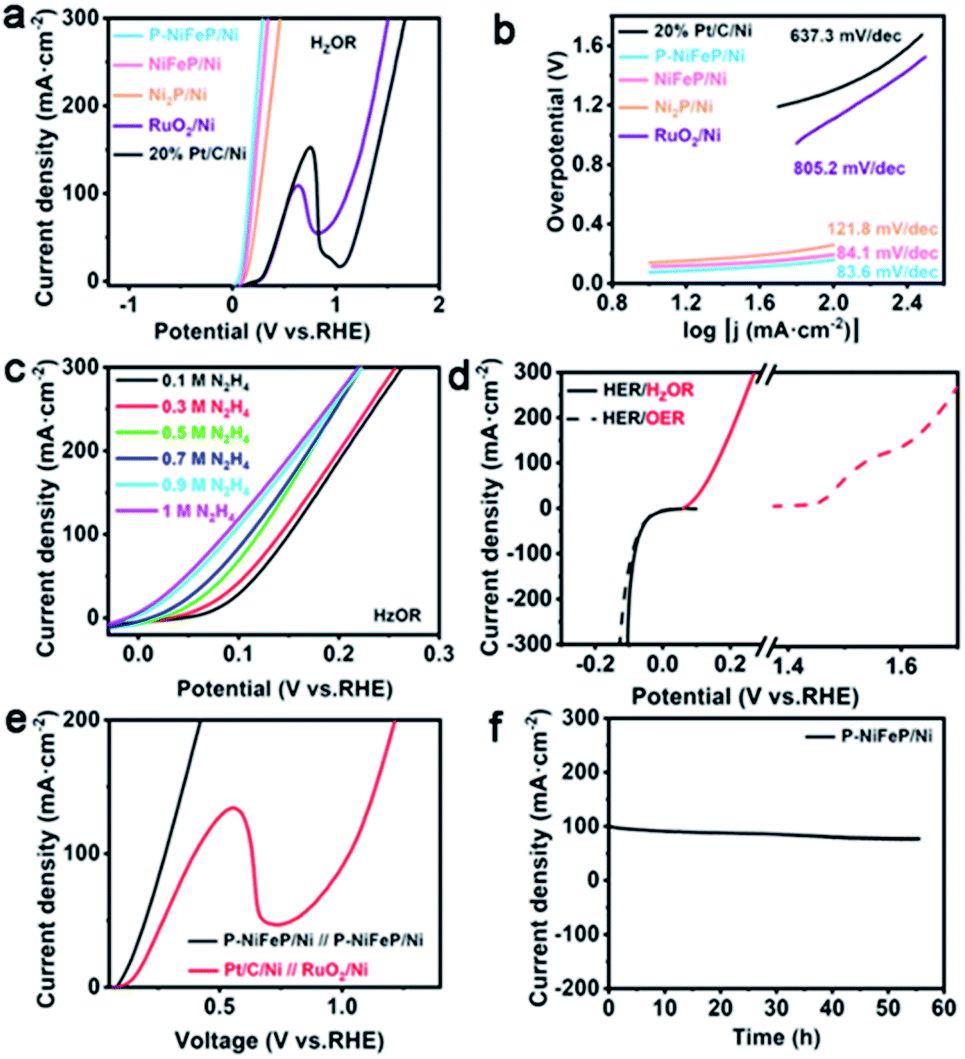
The HzOR performance of P-NiFeP/Ni was investigated using a typical three-electrode configuration, Ag/AgCl as a reference electrode and a carbon rod as the counter electrode in a basic electrolyte (containing 1.0 M KOH, 0.1 M N2H4). Fig. 4a shows the LSV curves of P-NiFeP/Ni, NiFeP/Ni, Ni2P/Ni, RuO2/Ni, and 20% Pt/C at the N2H4 concentration of 0.1 M, which indicates the much better electrocatalytic activity of P-NiFeP/Ni than that of others. Specifically, P-NiFeP/Ni only requires an ultralow working potential of 77 mV (vs. RHE) at 10 mA cm−2 current density, which is far more excellent than non-porous NiFeP/Ni and un-doped Ni2P/Ni, revealing the indispensability of dual regulation. P-NiFeP/Ni exceeds most of the reported materials (Table S4†). Fig. 4b shows that the Tafel slope of P-NiFeP/Ni is only 83.6 mV dec−1, which is lower than those of NiFeP/Ni (84.1 mV dec−1), Ni2P/Ni (121.8 mV dec−1), RuO2/Ni (805.2 mV dec−1), and 20% Pt/C (637.3 mV dec−1), implying the most favorable catalytic kinetics towards HzOR.
 | ||
| Fig. 4 (a) The LSV curves of as-synthesized samples in 1.0 M KOH + 0.1 M N2H4 aqueous at a scan rate of 5 mV s−1 and (b) the corresponding Tafel slope. (c) The LSV polarization curves of P-NiFeP/Ni with different hydrazine concentrations. (d) The comparison of LSV polarization curves of P-NiFeP/Ni for anodic oxidation with and without hydrazine. (e) LSV polarization curves of P-NiFeP/Ni‖P-NiFeP/Ni and 20% Pt/C‖RuO2/Ni for the HER/HzOR couple electrode. (f) The stability test for a P-NiFeP/Ni couple electrode. | ||
To further probe the catalytic activity of P-NiFeP/Ni towards HzOR, LSV curves with various hydrazine concentrations are recorded (Fig. 4c). The anode current density increases sharply with the increase of hydrazine concentration. Subsequently, when P-NiFeP/Ni was used as both the anode and cathode in the water electrolysis reaction, potential can reduce by about 1.38 V for electrolytic hydrogen generation with hydrazine electrolyte at 100 mA cm−2 (Fig. 4d). For the HER performance, P-NiFeP/Ni exhibits a similar overpotential of 17.2 mV (with hydrazine) and 17.9 mV (without hydrazine) versus RHE with 10 mA cm−2. The P-NiFeP/Ni couple electrode only needs a voltage of 162 mV at 10 mA cm−2 to realize the overall hydrazine splitting in the HER/HzOR system, which exhibits more excellent activity than the Pt/C//RuO2 couple electrode (Fig. 4e and S11†). The above result indicates that P-NiFeP/Ni is an effective bifunctional electrode for high-efficiency hydrazine oxidation and kinetics favorable for energy-saving hydrogen production. For oxidation reaction, the oxidation efficiency of the anode electrode is vital. The faradaic efficiency of the anode was evaluated by spectrophotometry of p-dimethylaminobenzaldehyde. As the maximum UV absorption wavelength of the reaction product is 460 nm, the product was quantified by an external standard method (Fig. S12a†). Upon applying a constant potential of 0.28 V vs. RHE, the transferred charge increased sharply, and approached 348.1C after around 1 h (Fig. S12b†). The content of hydrazine in electrolyte decreased gradually with the electrolysis reaction (Fig. S12b†). A charge of 348.1C for the oxidation of 10 ml 0.1 M N2H4 solution agrees well with the theoretically necessary charge for the complete 4e− oxidation of N2H4 to N2. The calculation shows that the faradaic efficiency is close to 99.8%.
Moreover, the long-term stability is tested via a constant potential method with 279 mV for 55 h, where a decaying current was observed but no significant change (Fig. 4f). The morphology and chemical composition of P-NiFeP/Ni after the stability test were investigated via XPS, XRD, SEM, and TEM. The XPS results show that Ni, Fe, and P elements are well preserved, verifying the chemical stability of the catalyst (Fig. S13a†). It is found that the relative strength of Ni 2p (Fig. S13b†) and Fe 2p (Fig. S13c†) in the catalyst increased after the test, which indicated that the intrinsic activity of P-NiFeP/Ni was exposed with the reaction. Furthermore, the relative strength of P 2p reduced remarkably after the test (Fig. S13d†), implying weak oxidation occurring on the catalyst surface during long-term hydrazine oxidation. As shown in Fig. S14–S16,† the components, crystal structure, and surface morphology are maintained well after the stability test, which suggested its good stability. These results demonstrate that P-NiFeP/Ni has potential applications toward hydrazine electro-oxidation.
Conclusions
In summary, we have reported a simple dual-regulation strategy to prepare P-NiFeP/Ni with a hierarchically porous structure and large electrochemically active surface area (Cdl = 53.6 mF cm−2), which exhibits favorable catalytic reaction kinetics, robust catalytic activity, and durability toward hydrazine oxidation. Specifically, Fe doping optimized the catalyst surface electronic states and improved the electronic binding energy of Ni atoms, which promoted the catalytic activity toward the hydrazine oxidation coupled energy-saving hydrogen evolution. Additionally, the perfect porous structure of the catalyst with a larger electrochemically active surface area was prepared by adjusting the content of phosphorus source, which increases the catalytically active sites and promotes the catalytic reaction kinetics. Importantly, the as-prepared P-NiFeP/Ni as both the anode and cathode catalyst for overall hydrazine splitting only required a potential of 162 mV to achieve 10 mA cm−2, which is attributed to the regulation of the dual-regulation strategy on the catalyst. This work not only offers a facile dual-regulation strategy for designing a well-controlled porous structure of the multifunctional catalyst but also provides guidance for the development of high efficiency and durable electrocatalysts for HzOR boosted H2 production.Experimental
Materials
Iron nitrate nonahydrate (Fe(NO3)3·9H2O), sodium hypophosphite, nickel nitrate hexahydrate (Ni(NO3)2·6H2O), urea, p-dimethylaminobenzaldehyde, and ammonium fluoride (NH4F) were obtained from Shanghai Aladdin Biochemical Technology Co., Ltd. Hydrazine hydrate (N2H4·H2O) was bought from Tianjin Kermel Chemical Reagent Company. All of the reagents were used directly without further treatment.Synthesis of flower-like Ni(OH)2·0.75H2O/Ni and Ni0.75Fe0.25(CO3)0.125(OH)2·0.38H2O/Ni (Pre-NiFe/Ni)
Flower-like Ni(OH)2·0.75H2O/Ni was obtained via a facile hydrothermal method. Firstly, nickel foam (NF, about 1.5 cm−2) was ultrasonicated with 3 M HCl aqueous solution for 40 min to remove the organics and the oxide on the NF surface, and then rinsed with deionized (DI) water several times. Secondly, Ni(NO3)2·6H2O (2 mmol), 2 mmol NH4F and 3 mmol urea were added to 40 ml of DI water and stirred for 5 min to form a green uniform mixed solution. Moreover, the NF was placed into a high-pressure autoclave (50 ml) at 87 °C for 15 h. The autoclave was then cooled naturally, and the sample was washed with DI water. The synthesis of Pre-NiFe/Ni is similar to that of Ni(OH)2·0.75H2O/Ni except that the 0.25 mmol iron salt is added into the solution with total metal amounts of 2 mmol.Synthesis of Ni2P/Ni, NiFeP/Ni, and P-NiFeP/Ni
The as-prepared Ni(OH)2·0.75H2O and an appropriate amount of NaH2PO2 were placed in a quartz boat. NaH2PO2 and Ni(OH)2·0.75H2O were placed on the upstream and downstream sides of the tubular furnace respectively, heated to 320 °C at a 2 °C min−1 heating rate, and maintained at that temperature for 3 h to form Ni2P/Ni. The synthesis of NiFeP/Ni is similar to that of Ni2P/Ni except that the precursor Ni(OH)2·0.75H2O was changed to Pre-NiFe/Ni. P-NiFeP/Ni was synthesized by adjusting the content of the phosphorus source. Specifically, the precursor Pre-NiFe/Ni was phosphated with the content of phosphorus source ranging from 0.1 g to 2.0 g. The best reaction condition is a phosphorus source content of 1.2 g, which shows the largest electrochemically active surface area.Physical characterization
The X-ray power diffraction (XRD) pattern of the as-prepared samples was recorded on a SmartLab 9 kW using Cu Kα (λ = 1.5406 Å) radiation. The scanning electron microscopy (SEM) images and corresponding energy-dispersive X-ray (EDS) data were collected using a scanning electron microscope (NOVA NanoSEM 450). The transmission electron microscopy (TEM) photos and corresponding EDS mapping data were obtained using a transmission electron microscope (Tecnai G2F30 STWIN). The element valence state and chemical composition were determined via X-ray photoelectron spectroscopy (ESCALAB XI+). The N2H4 concentration was analyzed by p-dimethylaminobenzaldehyde spectrophotometry at the maximum absorption wavelength of 460 nm using an UV/vis spectrometer (Persee TU-1900).Electrochemical measurements
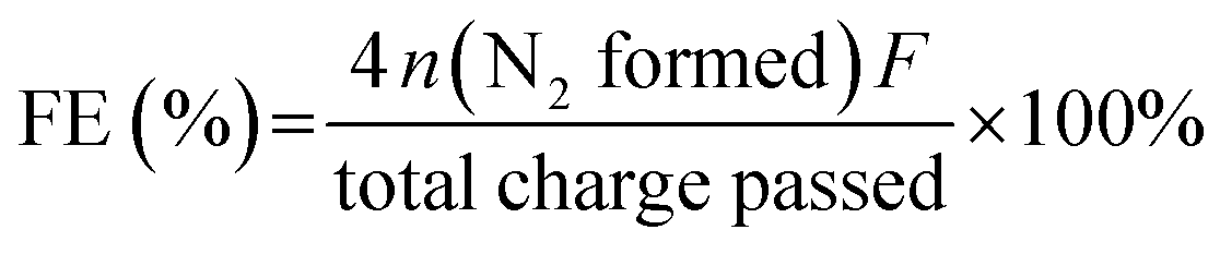
The electrochemical tests were performed using a CHI660E workstation (Shanghai Chenhua Instrument Co., Ltd) in 1.0 M KOH aqueous solution. All the electrochemical overpotentials tested were relative to the reversible hydrogen electrode (RHE). The equation follows: E (RHE) = E (Ag/AgCl) + 0.197 V + 0.059 × pH. The as-prepared samples were tested with 20 cycles of cyclic voltammetry (CV) before the test to activate the sample and remove the unstable components on the sample surface. Linear sweep voltammetry (LSV) was performed in an undivided-cell at a 5 mV s−1 scanning rate. The electrocatalyst ink was synthesized by adding 4 mg of 20% Pt/C or RuO2 into 1.0 ml of water and Nafion (30 μl) mixture solution under ultrasonic conditions. Then, 1 ml of the electrocatalyst ink was loaded on the Ni foam surface (1.5 cm−2) and dried naturally. The electrochemical double-layer capacitance (Cdl) was evaluated by cyclic voltammetry (CV) with different scan rates from 10 to 200 mV s−1 in the potential range of 0–0.2 V (vs. RHE). The active surface area of the as-prepared catalysts was estimated via the relationship between the sweep rate and electrorheological at 0.1 V in electrochemical double-layer capacitance cyclic voltammetry (CV) curve. Electrochemical impedance spectroscopy (EIS) at an overpotential of 100 mV was performed in the frequency range of 0.01 Hz to 100 kHz. The catalyst turnover frequency (TOF) was calculated by this formula: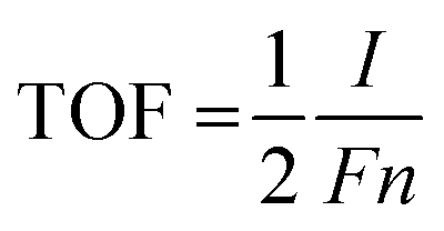 | (1) |
485 C). n (mol) represents the number of active sites of the catalyst: the cyclic voltammograms in the region of −0.2 V to 0.6 V vs. RHE in pH = 7 phosphate buffered solution.52 Because the total charge of cyclic voltammetry process is proportional to the total number of active sites in the whole potential range. Therefore, the total charge is calculated by measuring the absolute component of the voltammetric charge during cyclic voltammetry. The factor 1/2 is obtained via considering the two-electron transfer in the formation of the H2 molecule. Then, the TOF of the catalyst was estimated by the formula (1).53
The Faraday efficiency (FE) of the anode electrode was calculated by this formula:
 | (2) |
485 C mol−1) and n is the mol of N2 calculated from the N2H4 consumed concentration measured by p-dimethylaminobenzaldehyde spectrophotometry. 4 represents the number of electrons transferred during the reaction. The total charge passed is obtained by integrating the constant voltage test curve.
Conflicts of interest
There are no conflicts to declare.Acknowledgements
This study was financially supported by the National Natural Science Foundation of China (no. 21872018), and the Fundamental Research Funds for the Central Universities (DUT20GJ208).Notes and references
- T. R. Cook, D. K. Dogutan, S. Y. Reece, Y. Surendranath, T. S. Teets and D. G. Nocera, Chem. Rev., 2010, 110, 6474–6502 CrossRef CAS.
- X. Zou and Y. Zhang, Chem. Soc. Rev., 2015, 44, 5148–5180 RSC.
- H. F. Wang, L. Chen, H. Pang, S. Kaskel and Q. Xu, Chem. Soc. Rev., 2020, 49, 1414–1448 RSC.
- C. Liang, P. Zou, A. Nairan, Y. Zhang, J. Liu, K. Liu, S. Hu, F. Kang, H. J. Fan and C. Yang, Energy Environ. Sci., 2020, 13, 86–95 RSC.
- I. Roger, M. A. Shipman and M. D. Symes, Nat. Rev. Chem., 2017, 1, 0003 CrossRef CAS.
- P. Zhang, X. F. Lu, J. Nai, S. Q. Zang and X. W. Lou, Adv. Sci., 2019, 6, 1900576 CrossRef.
- H. Zhang, W. Zhou, J. Dong, X. F. Lu and X. W. Lou, Energy Environ. Sci., 2019, 12, 3348–3355 RSC.
- J. Y. Cai, Y. P. Zang, S. W. Niu, Y. S. Wu, Y. F. Xie, X. S. Zheng, Y. Liu, Y. Lin, X. J. Liu, G. M. Wang and Y. T. Qian, Sci. Adv., 2020, 6, eaaw8113 CrossRef CAS PubMed.
- G. Chen, Y. Zhu, H. M. Chen, Z. Hu, S. F. Hung, N. Ma, J. Dai, H. J. Lin, C. T. Chen, W. Zhou and Z. Shao, Adv. Mater., 2019, 31, 1900883 CrossRef.
- Q. Shi, C. Zhu, D. Du and Y. Lin, Chem. Soc. Rev., 2019, 48, 3181–3192 RSC.
- Y. Zhao, N. Yang, H. Yao, D. Liu, L. Song, J. Zhu, S. Li, L. Gu, K. Lin and D. Wang, J. Am. Chem. Soc., 2019, 141, 7240–7244 CrossRef CAS PubMed.
- L. Huang, X. Zhang, Q. Wang, Y. Han, Y. Fang and S. Dong, J. Am. Chem. Soc., 2018, 140, 1142–1147 CrossRef CAS PubMed.
- A. Dutta and J. Ouyang, ACS Catal., 2015, 5, 1371–1380 CrossRef CAS.
- J. Zheng, X. Chen, X. Zhong, S. Li, T. Liu, G. Zhuang, X. Li, S. Deng, D. Mei and J. G. Wang, Adv. Funct. Mater., 2017, 27, 1704169 CrossRef.
- H. G. Cha and K. S. Choi, Nat. Chem., 2015, 7, 328–333 CrossRef CAS PubMed.
- C. Wang, H. Lu, Z. Mao, C. Yan, G. Shen and X. Wang, Adv. Funct. Mater., 2020, 30, 2000556 CrossRef CAS.
- W. Liu, J. Xie, Y. Guo, S. Lou, L. Gao and B. Tang, J. Mater. Chem. A, 2019, 7, 24437–24444 RSC.
- T. J. Wang, G. R. Xu, H. Y. Sun, H. Huang, F. M. Li, P. Chen and Y. Chen, Nanoscale, 2020, 12, 11526–11535 RSC.
- Y. Liu, J. Zhang, Y. Li, Q. Qian, Z. Li, Y. Zhu and G. Zhang, Nat. Commun., 2020, 11, 1853 CrossRef CAS PubMed.
- E. H. Fragal, V. H. Fragal, X. Huang, A. C. Martins, T. S. P. Cellet, G. M. Pereira, E. Mikmeková, A. F. Rubira, R. Silva and T. Asefa, J. Mater. Chem. A, 2017, 5, 1066–1077 RSC.
- G. Feng, L. An, B. Li, Y. Zuo, J. Song, F. Ning, N. Jiang, X. Cheng, Y. Zhang and D. Xia, Nat. Commun., 2019, 10, 4514 CrossRef CAS PubMed.
- Z. Wang, L. Xu, F. Huang, L. Qu, J. Li, K. A. Owusu, Z. Liu, Z. Lin, B. Xiang, X. Liu, K. Zhao, X. Liao, W. Yang, Y. B. Cheng and L. Mai, Adv. Energy Mater., 2019, 9, 1900390 CrossRef.
- Y. Sun, S. Gao and Y. Xie, Chem. Soc. Rev., 2014, 43, 530–546 RSC.
- X. Du, J. Huang, J. Zhang, Y. Yan, C. Wu, Y. Hu, C. Yan, T. Lei, W. Chen, C. Fan and J. Xiong, Angew. Chem., Int. Ed., 2019, 58, 4484–4502 CrossRef CAS PubMed.
- Y. Yang, Z. Lin, S. Gao, J. Su, Z. Lun, G. Xia, J. Chen, R. Zhang and Q. Chen, ACS Catal., 2016, 7, 469–479 CrossRef.
- Y. Yao, S. Hu, W. Chen, Z. Q. Huang, W. Wei, T. Yao, R. Liu, K. Zang, X. Wang, G. Wu, W. Yuan, T. Yuan, B. Zhu, W. Liu, Z. Li, D. He, Z. Xue, Y. Wang, X. Zheng, J. Dong, C. R. Chang, Y. Chen, X. Hong, J. Luo, S. Wei, W. X. Li, P. Strasser, Y. Wu and Y. Li, Nat. Catal., 2019, 2, 304–313 CrossRef CAS.
- Y. Han, Y. Wang, R. Xu, W. Chen, L. Zheng, A. Han, Y. Zhu, J. Zhang, H. Zhang, J. Luo, C. Chen, Q. Peng, D. Wang and Y. Li, Energy Environ. Sci., 2018, 11, 2348–2352 RSC.
- T. Ling, T. Zhang, B. Ge, L. Han, L. Zheng, F. Lin, Z. Xu, W. B. Hu, X. W. Du, K. Davey and S. Z. Qiao, Adv. Mater., 2019, 31, 1807771 CrossRef.
- P. Li, X. Duan, Y. Kuang, Y. Li, G. Zhang, W. Liu and X. Sun, Adv. Energy Mater., 2018, 8, 1703341 CrossRef.
- Y. Fu, F. Cao, F. Wu, Z. Diao, J. Chen, S. Shen and L. Li, Adv. Funct. Mater., 2018, 28, 1706785 CrossRef.
- Y. Wang, X. Li, M. Zhang, Y. Zhou, D. Rao, C. Zhong, J. Zhang, X. Han, W. Hu, Y. Zhang, K. Zaghib, Y. Wang and Y. Deng, Adv. Mater., 2020, 32, 2000231 CrossRef CAS PubMed.
- H. Xu, C. Shan, X. Wu, M. Sun, B. Huang, Y. Tang and C. H. Yan, Energy Environ. Sci., 2020, 13, 2949–2956 RSC.
- C. Wang and L. Qi, Angew. Chem., Int. Ed., 2020, 59, 17219–17224 CrossRef CAS.
- A. L. Wang, H. Xu and G. R. Li, ACS Energy Lett., 2016, 1, 445–453 CrossRef CAS.
- H. Li, M. Hu, L. Zhang, L. Huo, P. Jing, B. Liu, R. Gao, J. Zhang and B. Liu, Adv. Funct. Mater., 2020, 30, 2003198 CrossRef CAS.
- X. Zhou, N. Liu, J. Schmidt, A. Kahnt, A. Osvet, S. Romeis, E. M. Zolnhofer, V. R. Marthala, D. M. Guldi, W. Peukert, M. Hartmann, K. Meyer and P. Schmuki, Adv. Mater., 2017, 29, 1604747 CrossRef PubMed.
- J. Huang, Y. Li, R. K. Huang, C. T. He, L. Gong, Q. Hu, L. Wang, Y. T. Xu, X. Y. Tian, S. Y. Liu, Z. M. Ye, F. Wang, D. D. Zhou, W. X. Zhang and J. P. Zhang, Angew. Chem., Int. Ed., 2018, 57, 4632–4636 CrossRef CAS PubMed.
- X. Li, Y. Zhao, Y. Yang and S. Gao, Nano Energy, 2019, 62, 628–637 CrossRef CAS.
- Y. Xiao, G. Tian, W. Li, Y. Xie, B. Jiang, C. Tian, D. Zhao and H. Fu, J. Am. Chem. Soc., 2019, 141, 2508–2515 CrossRef CAS PubMed.
- Y. Shi and B. Zhang, Chem. Soc. Rev., 2016, 45, 1529–1541 RSC.
- Y. Yang, H. Yao, Z. Yu, S. M. Islam, H. He, M. Yuan, Y. Yue, K. Xu, W. Hao, G. Sun, H. Li, S. Ma, P. Zapol and M. G. Kanatzidis, J. Am. Chem. Soc., 2019, 141, 10417–10430 CrossRef CAS PubMed.
- R. Q. Li, B. L. Wang, T. Gao, R. Zhang, C. Xu, X. Jiang, J. Zeng, Y. Bando, P. Hu, Y. Li and X. B. Wang, Nano Energy, 2019, 58, 870–876 CrossRef CAS.
- S. S. Lu, L. M. Zhang, Y. W. Dong, J. Q. Zhang, X. T. Yan, D. F. Sun, X. Shang, J. Q. Chi, Y. M. Chai and B. Dong, J. Mater. Chem. A, 2019, 7, 16859–16866 RSC.
- C. Liang, P. Zou, A. Nairan, Y. Zhang, J. Liu, K. Liu, S. Hu, F. Kang, H. J. Fan and C. Yang, Energy Environ. Sci., 2020, 13, 86–95 RSC.
- Y. Li, H. Zhang, M. Jiang, Q. Zhang, P. He and X. Sun, Adv. Funct. Mater., 2017, 27, 1702513 CrossRef.
- Q. Liu, H. Zhang, J. Xu, L. Wei, Q. Liu and X. Kong, Inorg. Chem., 2018, 57, 15610–15617 CrossRef CAS PubMed.
- C. F. Fu, X. Wu and J. Yang, Adv. Mater., 2018, 30, 1802106 CrossRef PubMed.
- G. Yang, Y. Jiao, H. Yan, Y. Xie, A. Wu, X. Dong, D. Guo, C. Tian and H. Fu, Adv. Mater., 2020, 32, 2000455 CrossRef CAS PubMed.
- X. F. Lu, L. Yue and X. W. Lou, Adv. Sci., 2019, 5, eaav6009 CrossRef CAS PubMed.
- J. Liu, Z. Wang, J. David, J. Llorca, J. Li, X. Yu, A. Shavel, J. Arbiol, M. Meyns and A. Cabot, J. Mater. Chem. A, 2018, 6, 11453–11462 RSC.
- H. Huang, C. Yu, C. Zhao, X. Han, J. Yang, Z. Liu, S. Li, M. Zhang and J. Qiu, Nano Energy, 2017, 34, 472–480 CrossRef CAS.
- D. Merki, S. Fierro, H. Vrubel and X. Hu, Chem. Sci., 2011, 2, 1262–1267 RSC.
- G. Chen, T. Wang, J. Zhang, P. Liu, H. Sun, X. Zhuang, M. Chen and X. Feng, Adv. Mater., 2018, 30, 1706279 CrossRef PubMed.
Footnote |
| † Electronic supplementary information (ESI) available. See DOI: 10.1039/d1na00043h |
| This journal is © The Royal Society of Chemistry 2021 |