
 Open Access Article
 This Open Access Article is licensed under a Creative Commons Attribution-Non Commercial 3.0 Unported Licence
Hydrous cobalt–iridium oxide two-dimensional nanoframes: insights into activity and stability of bimetallic acidic oxygen evolution electrocatalysts†
Yuanfang
Ying
a,
Jose Fernando
Godínez Salomón
 b,
Luis
Lartundo-Rojas
c,
Ashley
Moreno
b,
Robert
Meyer
b,
Craig A.
Damin
b and
Christopher P.
Rhodes
*ab
b,
Luis
Lartundo-Rojas
c,
Ashley
Moreno
b,
Robert
Meyer
b,
Craig A.
Damin
b and
Christopher P.
Rhodes
*ab
aMaterials Science, Engineering and Commercialization Program, Texas State University, San Marcos, TX 78666, USA. E-mail: cprhodes@txstate.edu
bDepartment of Chemistry and Biochemistry, Texas State University, San Marcos, TX 78666, USA
cInstituto Politécnico Nacional, Centro de Nanociencias y Micro y Nanotecnologías, UPALM, Zacatenco, CP 07738, Ciudad de México, Mexico
First published on 5th February 2021
Abstract
Acidic oxygen evolution reaction (OER) electrocatalysts that have high activity, extended durability, and lower costs are needed to further the development and wide-scale adoption of proton-exchange membrane electrolyzers. In this work, we report hydrous cobalt–iridium oxide two-dimensional (2D) nanoframes exhibit higher oxygen evolution activity and similar stability compared with commercial IrO2; however, the bimetallic Co–Ir catalyst undergoes a significantly different degradation process compared with the monometallic IrO2 catalyst. The bimetallic Co–Ir 2D nanoframes consist of interconnected Co–Ir alloy domains within an unsupported, carbon-free, porous nanostructure that allows three-dimensional molecular access to the catalytically active surface sites. After electrochemical conditioning within the OER potential range, the predominately bimetallic alloy surface transforms to an oxide/hydroxide surface. Oxygen evolution activities determined using a rotating disk electrode configuration show that the hydrous Co–Ir oxide nanoframes provide 17 times higher OER mass activity and 18 times higher specific activity compared to commercial IrO2. The higher OER activities of the hydrous Co–Ir nanoframes are attributed to the presence of highly active surface iridium hydroxide groups. The accelerated durability testing of IrO2 resulted in lowering of the specific activity and partial dissolution of Ir. In contrast, the durability testing of hydrous Co–Ir oxide nanoframes resulted in the combination of a higher Ir dissolution rate, an increase in the relative contribution of surface iridium hydroxide groups and an increase in specific activity. The understanding of the differences in degradation processes between bimetallic and monometallic catalysts furthers our ability to design high activity and stability acidic OER electrocatalysts.
Introduction
Electrolysis of water generates hydrogen that can be used for fuel cells and other applications and be powered by renewable energy sources such as wind and solar power.1 Water electrolyzers can be coupled with renewable energy sources to store typically unused energy during off-peak times and be used as a load levelling device based on the variable, intermittent nature of wind and solar power generation. Significant challenges for proton exchange membrane water electrolyzers (PEM-WE) include reducing the required input power, reducing the catalyst precious metal content, and improving the catalyst stability.1–3 In contrast to the fast kinetics for the cathodic hydrogen evolution reaction, the anodic oxygen evolution reaction (OER), which involves the removal of four electrons and protons from water and the formation of an oxygen–oxygen double bond, exhibits sluggish kinetics that results in high overpotentials.4 For acidic PEM-WEs, platinum-group metals (Ru, Ir, Pt) have been evaluated as acidic OER electrocatalysts.5–7 Iridium-based catalysts have shown good OER catalytic activities6 and reasonable stability under the highly corrosive anodic potentials and acidic environment required for OER.8 Unfortunately, iridium is one of the rarest elements in the Earth's crust with an average mass fraction of 0.001 ppm.1 To make PEM-WEs feasible on a large scale, the amount of Ir required must be significantly reduced.To lower the Ir content, improvements in the activity and stability of Ir-based acidic OER catalysts are needed. A number of approaches have been explored including lowering the Ir loading on the electrode,9 using supported Ir catalysts (e.g. TiO2-supported, SnO2-supported Ir, etc.),10,11 and increasing the activity of Ir using through substitution with non-precious metals (e.g. Ni, Co, Cu, etc.).12–14 Prior density functional theory (DFT) calculations showed that IrO2 binds adsorbed oxygen too strongly which contributes to increasing the overpotential for the OER.15 A prior experimental study showed that Ni substituted within IrO2 resulted in increased OER activity attributed to leaching of Ni atoms, which promote the formation of structurally flexible, reactive OH groups that act as reactive surface intermediates for the OER catalytic reaction.16 Other work reported that the substitution of Cu within IrO2 creates oxygen vacancies and changes in the electron occupancy of the t2g and eg orbital states, resulting in lower overpotentials.17
In addition to increasing activity, the stability of OER catalyst remains a significant challenge1,7,18–20 since all known OER catalysts with reasonable activity (including Ir) dissolve under the highly acidic and oxidative potentials required for oxygen evolution.7,18,19 Within substituted IrO2-based catalysts, stability remains a major challenge since many of the metals such as Ni, Co and Cu are thermodynamically unstable in acid at high potentials, as described by Pourbaix diagrams21 and dissolve under OER testing conditions. Another factor affecting activity and stability is the surface structure. Prior work supports that there are significant surface structure, activity and stability differences between thermally prepared iridium oxides (IrO2) and amorphous, electrochemically generated iridium oxides (IrOx).19 The predominant current understanding of acidic OER catalysts is that activity and stability are inherently linked since they share a common intermediate.20,22 Prior work on noble metal monometallic oxides established a direct relationship between the high activity and low stability of acidic OER catalysts;5 however, others' work on RuO2 catalysts reports no correlation between activity and stability.23 Recent work suggests that it may be possible to obtain catalysts that are not restricted by the traditional inverse relationship between OER activity and stability.24
Cobalt is a potentially promising substituent within IrO2 for improving OER activity since doping of Co within IrO2 was shown from DFT calculations to alter the electron density and influence changes in the binding energies of intermediates resulting in structures with lower activation energies.25 A number of prior studies have evaluated developing improved acidic OER catalysts through interacting iridium and cobalt within iridium–cobalt nanowires,3 iridium–cobalt porous nanocrystals,26 iridium–cobalt oxide,27,28 IrO2–Co3O4 nanorods,29 and cobalt-doped SrIrO3.30 Nanoframe structures that combine iridium with Pt31 or Ni and Cu32 have been previously studied to enhance the activity and stability of oxygen evolution electrocatalysts. The catalyst structure and resulting OER activity and stability are highly dependent on the starting materials and chemical and electrochemical processes used to generate the active catalyst.33
Our group has developed bimetallic two-dimensional (2D) nanoframes that combine highly active bimetallic surface sites and a porous, carbon-free nanoarchitecture to provide oxygen electrocatalysts with improved activity and stability.14,34,35 The 2D nanoframe structure is synthesized from thermal reduction of precious metal-decorated metal oxide nanosheets and is composed of a unique hierarchical 2D framework containing interconnected solid metallic alloy domains within a porous matrix that provides 3D molecular accessibility. We recently reported unsupported, hydrous iridium–nickel oxide 2D nanoframes exhibit 14 times higher OER mass activity than commercial IrO2.14 In this prior study, we used interaction of Ir with Ni within the structure to significantly enhance OER activity and the porous unsupported electrocatalyst structure to provide access to the active sites and avoid support degradation and nanoparticle aggregation. However, the stability of the hydrous iridium–nickel oxide nanoframes was substantially lower than IrO2. We recently reported the combination of CoIr and NiPt 2D nanoframes function as highly efficient bifunctional oxygen reduction/evolution electrocatalysts;35 however, our recent study did not explore CoIr nanoframes separately as oxygen evolution catalysts. In this work, we report the morphological and structural characterization of CoIr nanoframes and precursor materials, electrochemical and spectroscopic characterization of the surface structure, and evaluation of the oxygen evolution activity and stability compared with commercial IrO2 to provide insight into how cobalt interacting with iridium within a 2D nanoframe structure affects OER activity and stability.
Experimental methods
Synthesis
Co(OH)2 nanosheets and iridium-decorated Co(OH)2 nanosheets, notated as Co(OH)2:Ir, were prepared by adapting a microwave-assisted hydrothermal synthesis method previously reported by our group for preparation of Ni(OH)2 and Ni(OH)2:Ir.14 The synthesis process is summarized in Fig. 1A. The synthesis of Co–Ir nanoframes involved four steps: (i) formation of Co(OH)2 nanosheets using an rapid (10 min) microwave assisted process; (ii) deposition of Ir nanoparticles on α-Co(OH)2 nanosheets; (iii) controlled thermal treatment under reducing atmosphere (H2/Ar, 5/95 vol%); and (iv) a chemical leaching step in nitric acid (0.05 M HNO3) to remove unstable metallic Co.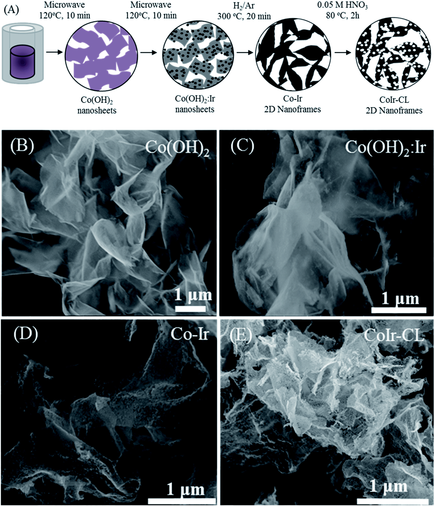 | ||
| Fig. 1 (A) Schematic representation of the experimental steps for the synthesis of two-dimensional (2D) CoIr-CL nanoframes; representative secondary electron images obtained by scanning electron microscopy (SEM) for (B) Co(OH)2 nanosheets, (C) Ir-decorated Co(OH)2 (Co(OH)2:Ir), (D) after thermal treatment of Co(OH)2:Ir under H2/Ar at 300 °C (Co–Ir), and (E) after chemical leaching of Co–Ir in 0.05 M HNO3 at 80 °C for 2 h (CoIr-CL). | ||
To prepare the Co(OH)2 nanosheets, 1.05 g of Co(NO3)2·6H2O (98%, Alfa Aesar) was combined with 0.6486 g of urea (99.3%, Alfa Aesar) in 3 mL of ultrapure water (≥18 MΩ cm, in-house water purification system, Purelab Classic, Evoqua Water Technologies) and 21 mL of ethylene glycol (99%, VWR). The solution was then transferred into a 35 mL microwave vial. The reaction was conducted in a Discover SP Microwave reactor under variable microwave radiation power with a controlled temperature of 120 °C for 10 min under active magnetic stirring. The powder was separated by centrifugation (Sorvall ST16, Thermo) at 3000 RPM for 3 min, rinsed five times with ultrapure water and two times with isopropanol (HPLC grade, VWR), and then dried under ambient atmosphere at 60 °C.
To synthesize iridium-decorated Co(OH)2 nanosheets (Co(OH)2:Ir), 0.038 g of IrCl3·xH2O (99.8%, Alfa Aesar) (equivalent to 20 wt% of Ir vs. Co(OH)2) was dissolved in 25 mL of ultrapure water, and 0.1 g of Co(OH)2 was added. The suspension was then transferred into a 35 mL microwave vial. The reaction was conducted in a microwave reactor under variable microwave radiation power with a controlled temperature of 120 °C for 10 min with active stirring and then separated using an identical reactor and conditions as described above. The Co(OH)2:Ir nanosheets were thermally treated within a muffle furnace (Lindberg Blue M, Thermo Scientific) at 300 °C for 20 minutes using a ramp rate of 10 °C min−1 starting from room temperature and under 120 mL min−1 flowing H2/Ar (5/95 vol%). Then, the reactor was removed from the oven and allowed to cool under H2/Ar flow until reaching room temperature. The synthesized sample after thermal treatment is notated as Co–Ir. CoIr-CL was prepared by chemically leaching of Co–Ir using a method previously reported by our group.14,35 Briefly, 0.2 g of the as-prepared Co–Ir nanoframes were dispersed in 100 mL of 0.05 M HNO3 which was diluted from 70% HNO3 (99.999%, Aldrich). The solution was bubbled with flowing Ar for 20 min and then heated to 80 °C for 2 hours under stirring. The Ar flow was maintained until the reaction completed. After the reaction, the suspension was cooled to room temperature. The solid was separated by centrifugation at 5000 RPM for 10 min, rinsed five times with ultrapure water, rinsed two times with isopropanol, and then dried at 60 °C. The samples are noted as Co(OH)2 (Co(OH)2 nanosheets), Co(OH)2:Ir (decorated Co(OH)2 nanosheets with Ir nanoparticles), Co–Ir (Co(OH)2:Ir treated at 300 °C under H2/Ar), and CoIr-CL (Co–Ir after chemical leaching).
Physical and structural characterization
Scanning electron microscopy (SEM) and energy dispersive X-ray spectroscopy (EDS) elemental mapping were obtained with a Helios NanoLab 400 DualBeam Field Emission Scanning Electron Microscope. The samples were prepared by dispersing the catalyst in isopropanol and coating the sample on an aluminum holder. Powder X-ray diffraction (XRD) measurements were collected using a Bruker AXS D8 Advance powder X-ray diffractometer with a Cu Kα (λ = 1.5406 Å) radiation source, operating at 40 kV and 25 mA and a high-resolution energy dispersive 1D Linxeye XE detector. The XRD scan range was 5° < 2θ < 80° and used a 0.01° increment.X-ray photoelectron spectra were obtained using a Thermo Fischer Scientific K-Alpha X-ray photoelectron spectrometer with a monochromatic Al Kα X-ray source, 1486.6 eV, microfocused at the source to give a spot size on the sample of 400 microns in diameter. Samples remained under vacuum for more than 10 h in a prechamber directly connected to the equipment and were then transferred to the analysis chamber with a base pressure of 1 × 10⁻⁹ Torr that remained constant during the experiment. Survey and high-resolution spectra were collected using an analyzer, operated in Constant Analyser Energy mode (CAE), with pass energies of 200 and 10 eV, respectively. In order to compensate effects related to charge shift, the Ir4f7/2 metal peak at 60.2 eV and the C1s adventitious carbon peak at 284.6 eV were used as internal standards. Data analysis was performed using AVANTAGE v5.91 software (Thermo Fisher Scientific) using a Shirley-type background subtraction and a pseudo-Voigt function with Gaussian (70%)–Lorentzian (30%) for each component. XPS analysis was carried out from two independent batches of each catalyst material to determine any significant changes in the number and content of chemical elements between batches of the same material. In each lot, survey and high-resolution spectra were obtained from three different zones with diameters of 400 microns. From the examination of the survey spectra, it was established that among batches of the same sample the chemical elements present were the same and that these did not present significant changes, ≤1.0, in their atomic percentage content. On the other hand, the high resolution spectra for the Ir5p–Ir4f, O1s and Co2p regions suggested that between batches of the same sample, there were some changes in the atomic percentage content but not in the number of chemical species formed during the synthesis protocol (Fig. S6 and S7†). In view of these results, it was established that both catalytic systems have a homogeneous elemental and chemical species composition. Therefore, for each material average survey and high-resolution spectra from the whole set of data obtained were generated for further analysis. XPS spectra and quantities presented correspond to an average of six measurements from different points of each sample batch.
Attenuated total reflectance Fourier-transform infrared (ATR-FT-IR) spectra of the Co(OH)2 and Co–Ir samples were collected using a Harrick Scientific (Pleasantville, NY) SplitPea ATR microsampling accessory coupled to a Bruker (Billerica, MA) Tensor II FT-IR spectrometer. The SplitPea accessory was equipped with a silicon internal reflection element and utilized a liquid nitrogen cooled mercury–cadmium–telluride detector coupled to the Tensor II spectrometer. The solid samples were brought into direct contact with the silicon internal reflection element using a 0.5 kg loading. Infrared spectra represent the average of 64 individual scans with 4 cm−1 resolution. Transmission FT-IR measurements were obtained within the instrument described above using potassium bromide (KBr) pellets prepared by combining the sample with dried KBr powder.
Rotating disk electrochemical characterization
The electrochemical measurements of the catalyst materials were conducted at constant temperature (298 K) in a three-electrode cell using a thin-film rotating disk electrode (TF-RDE) configuration with an Autolab PGSTAT128N bipotentiostat and rotation control (Pine Instruments). A gold disk electrode (RDE, Pine Research instrument, geometric area: 0.196 cm2) with a thin film of the prepared catalyst was used as the working electrode, and a Pt mesh and a freshly prepared reversible hydrogen electrode (RHE) were used as counter and reference electrodes, respectively.The electrode fabrication and RDE testing protocols were based on methods previously reported by our group14,35 and other groups.36 Catalyst inks were prepared by combining a specific mass (typically ∼3 mg) of the acid-leached catalysts (CoIr-CL) with a specific volume of a stock solution to yield a catalyst concentration of 0.43 mgcat mL−1. The stock solution was prepared by mixing 0.4 mL of Nafion suspension (Aldrich, 5 wt%, 1100 g equivalent weight), 20 mL of isopropanol, and 79.6 mL ultrapure water (≥18 MΩ cm). The inks were sonicated (Fisher, 40 kHz) in an ice-bath for 20 minutes. The ink was then immersed in a controlled temperature bath (25 °C) for 1 minute while maintaining agitation and was then used immediately. The inks were applied to a polished Au working electrode (0.196 cm2 geometric area) and allowed to dry under rotation (700 rpm) under ambient conditions. The electrode loading was controlled by depositing a specific volume of the ink onto the Au working electrode. For the CoIr-CL catalysts, 10 uL was deposited onto the Au electrode which corresponds to a loading of 15.3 μg Ir cmgeo−2. After depositing the ink on the rotating Au electrode, the ink was maintained under rotation and allowed to dry under ambient conditions.
The electrochemical characterization of the catalysts was carried out in 0.1 M HClO4 electrolyte prepared with 70% HClO4 (Veritas Doubly Distilled, GFS Chemicals) (0.000001% Cl−) and ultrapure water. For the electrochemical tests, the Au working electrode was placed in a three-electrode cell with the 0.1 M HClO4 electrolyte. The electrodes were immersed in argon saturated 0.1 M HClO4 under potential control (0.1 VRHE). The catalysts were first conditioned by cycling 20 times from 0.05–1.0 VRHE at 100 mV s−1. The electrochemical surface area (ECSA) of metallic Ir was calculated by CO-stripping using a specific charge of 358 μC cm−2 as the charge corresponding to a monolayer of adsorbed CO.36 Prior to the analysis in the OER potential range, the catalysts were electrochemically conditioned by cycling between 0.05 to 1.5 VRHE for 60 cycles at a scan rate of 100 mV s−1 in argon-saturated 0.1 M HClO4, which is designated as the electrochemical oxidation (EO) step. The electrochemical surface area of IrO2 (ECSAIrO2) was then determined by measuring the pseudocapacitive charge between 0.3 V and 1.25 V obtained using a scan rate of 50 mV s−1 and by subtracting the contribution of the Au disk current collector. The electrochemical surface area was calculated based on the background subtracted pseudocapacitive charge and the coulombic conversion factor of 596 μC cmIrO2−2.37
For evaluating the oxygen evolution reaction activity, the electrode was then conditioned by cycling 10 times in the potential range 1.2–1.8 VRHE at 100 mV s−1 and 2500 rpm. Linear sweep voltammetry (LSV) in the potential range of 1.2–1.8 VRHE was performed using a scan rate of 20 mV s−1 and a rotation rate of 2500 rpm. Steady-state (iR-corrected) chronoamperometric measurements were then performed by stepping the potential at steps of 0.01 V from 1.3 to 1.6 VRHE while holding for 5 seconds at each potential and rotating the working electrode at 2500 rpm. The internal resistance (iR) values (23–27 Ω) was determined prior to every evaluation using the current interruption method at 1.6 VRHE. The data obtained from chronoamperometric measurements was used for the Tafel plots and for determining the OER mass activity and specific activity. The mass-normalized OER activity was determined by the current at a specific voltage from the chronoamperometric measurements divided by the Ir mass on the electrode. The Ir mass on the electrode was determined by the mass loading and the Ir content within the material determined by inductively coupled plasma mass spectrometry (ICP-MS) analysis for CoIr-CL and for IrO2 from the certificate of analysis reported by the vendor (84.5 wt%) which was also corroborated by EDS measurements. The actual Ir mass after EO and after accelerated durability testing (ADT) was determined by subtracting the Ir leached into the electrolyte from the initial Ir mass on the electrode. The percent of Ir leached into the solution was determined by ICP-MS after each procedure, EO and ADT, for CoIr-CL and ADT for IrO2. Inspection of the Tafel plots for linear behavior within specific voltage ranges was used to evaluate that the electrode was not within a mass-transport limited regime within the specific voltage range. Tafel slopes were determined using current obtained from chronoamperometry measurements using the iR-corrected potential between 1.47 V to 1.52 VRHE. After the evaluation of the electrocatalyst in the OER potential range, CV measurements were again obtained to determine the nature of the surface after exposure to OER potentials of up to 1.8 VRHE.
Following the measurements of the OER activity, an accelerated durability test was carried out by maintaining the electrode at a constant potential of 1.6 VRHE for 13.5 hours under a rotation rate of 2500 rpm. After the constant potential step was completed, the electrolyte was replaced, and a 15 minute argon purge was performed to help remove entrapped oxygen bubbles within the catalyst layer which can contribute the influencing the oxygen evolution reaction current using RDE measurements.38 CV, CO stripping, LSV, and chronoamperometry measurements were then obtained as described above. ICP-MS measurements (PerkinElmer NexIon 2000, Washington University in Saint Louis) were used to analyze the amount of iridium dissolved within the electrolyte after the electrochemical oxidation step and after the accelerated durability test.
Results and discussion
Analysis of the morphology and elemental composition of cobalt–iridium nanoframes and precursor materials
The morphology and elemental composition of the cobalt–iridium nanoframes and precursor materials were determined by scanning electron microscopy (SEM), energy dispersive X-ray spectroscopy (EDS), and inductively coupled plasma atomic emission spectroscopy (ICP-AES). We evaluated the structure at each step of the synthesis process (Fig. 1A) to provide insight into how each step affects the structure of the CoIr-CL catalyst material. The SEM image of the Co(OH)2 nanosheets precursor (Fig. 1B), shows the structure consists of extended ultra-thin nanosheets with lateral sizes in the range of 2–5 μm and thicknesses of ∼10 nm. The morphology of the Co(OH)2 nanosheets is similar to that of α-Ni(OH)2 nanosheets synthesized using a similar protocol.14 After the Ir deposition step, the morphology of Co(OH)2:Ir (Fig. 1C) remained similar to that of the parent Co(OH)2 nanosheet material, but pores were also observed (Fig. S1†). Following thermal treatment of Co(OH)2:Ir under hydrogen, (i.e. H2/Ar, 300 °C), the extended 2D morphology remained; however, significant structural changes occurred, resulting in the formation of Co–Ir 2D nanoframes consisting of interconnected short “nanofilaments” that form a three-dimensional porous network (Fig. 1D). The chemical treatment of Co–Ir in acid maintained the 2D nanoframe morphology (Fig. 1E); in addition, the removal of unstable Co species from Co–Ir resulted in the formation of micropores as detected by scanning transmission electron microscopy measurements, as discussed below.The changes in the relative elemental composition and distribution of elements within the materials through the synthesis steps were followed by EDS (Fig. 2). In general, the as-prepared, intermediate materials, and final catalyst showed a homogeneous distribution of Co and Ir within the structures. The Co(OH)2:Ir material contained 23.1 ± 3.5 wt% of Ir, very close to the nominal weight ratio determined from weights of the precursors used for the synthesis (i.e. 20 wt%), which demonstrates good reaction efficiency. After thermal treatment of Co(OH)2:Ir at 300 °C under H2/Ar, within Co–Ir the elemental composition of Ir and Co increased to 36.0 ± 1.8 wt% iridium and 46.0 ± 2.9 wt% cobalt and the oxygen content decreased to 17.3 ± 4.3 wt%, which is attributed primarily to the removal of water from the structure as a product of the reaction. After the acid leaching step which selectively removed Co species, the CoIr-CL sample had a content of 88.3 ± 1.5 wt% iridium, 5.2 ± 0.6 wt% cobalt and 6.3 ± 2.0 wt% oxygen. The elemental composition of CoIr-CL determined from EDS was similar to the elemental composition determined by inductively coupled plasma atomic emission spectroscopy (ICP-AES), which yielded a content of 83 ± 2.7 wt% Ir and 9.3 ± 1.0 wt% Co for CoIr-CL. Although metallic Co is thermodynamically unstable in acid,21 we considered that Co within CoIr-CL could be stabilized from dissolution in acidic electrolyte through interaction of Co with Ir as supported by prior studies of Ni stabilization within IrO2.12,14
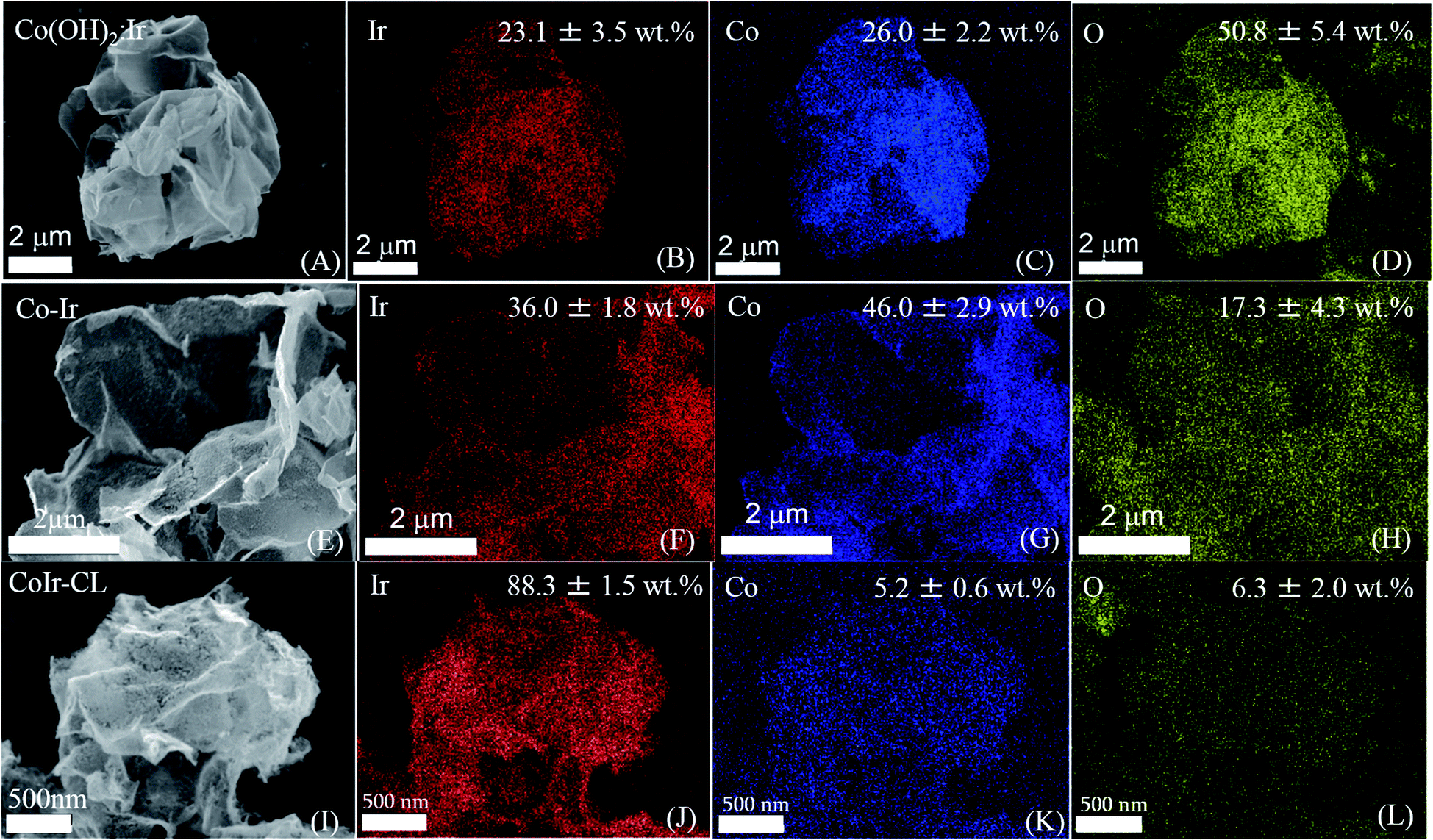 | ||
| Fig. 2 Scanning electron microscopy (SEM) images and energy-dispersive X-ray spectroscopy (EDS) mapping analysis of Co(OH)2:Ir (A–D); CoIr (E–H); and CoIr-CL (I–L) showing quantification and distribution of iridium, cobalt, and oxygen within the structures. | ||
X-ray diffraction characterization
The structures of the precursor materials and final catalyst were determined using powder X-ray diffraction (XRD). Shown in Fig. 3 are the powder XRD patterns for Co(OH)2, Co(OH)2:Ir, Co–Ir, and CoIr-CL along with patterns obtained from the crystallography open database (COD) used as references: α-Co(OH)2 (96-900-9102), Co3O4 (96-900-5893), metallic Co (96-901-0969) and metallic Ir (96-901-2961). The XRD pattern of Co(OH)2 exhibited a strong reflection at a 2θ value of 12.1°, assigned to the (001) basal plane arising from the preferential orientation of the nanosheets.39 The slight differences of the diffraction angles of the synthesized α-Co(OH)2 compared with a prior study39 may be related with changes of the interlayer spacing and structural disorder, produced by the presence of different intercalated anions and/or differences in water content.34,39–41 The presence of water and ethylene glycol (EG) species within the synthesized α-Co(OH)2 was further confirmed by Fourier-transform infrared spectroscopy as discussed below. We note that the presence of ethylene glycol and water within α-Co(OH)2 may play an important role in the formation of the nanosheet structure.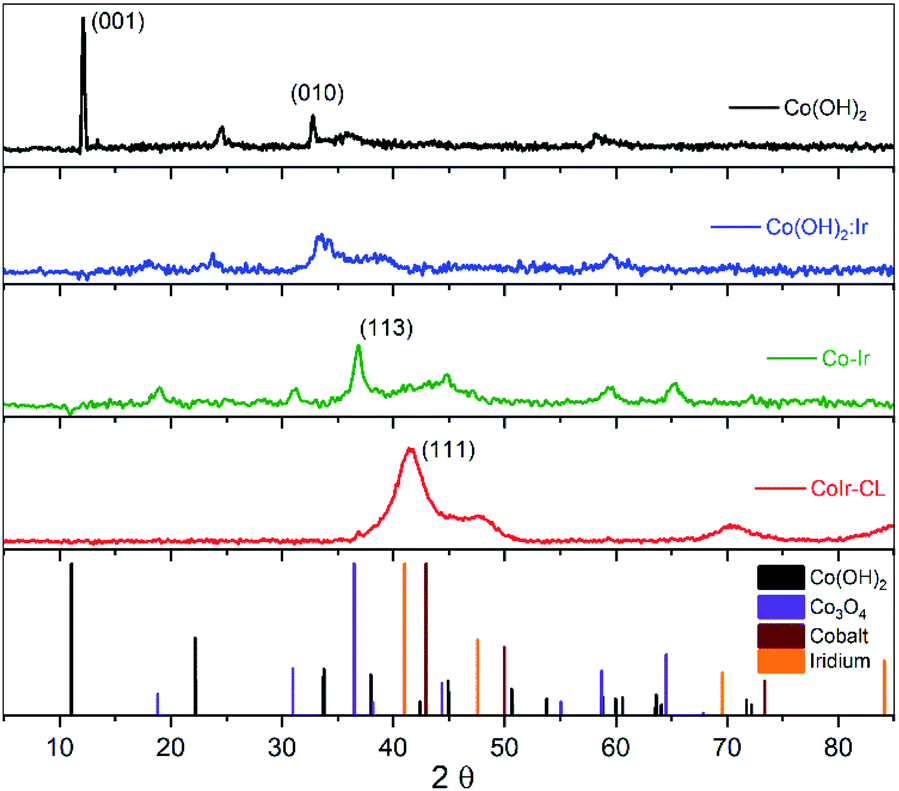 | ||
| Fig. 3 Powder X-ray diffraction (XRD) patterns of Co(OH)2, Co(OH)2:Ir, Co–Ir, CoIr-CL and patterns for references (α-Co(OH)2, Co3O4, Co, and Ir). | ||
After Ir deposition, the XRD pattern of Co(OH)2:Ir showed the strong peak associated with the (001) basal plane of Co(OH)2 disappeared, while small peaks around 18° and 59° associated with a Co3O4 phase were present. The disappearance of the (001) peak within Co(OH)2:Ir is attributed to the disruption of the basal plane which may be influenced by the creation of pores within the structure as observed by microscopy (Fig. S1†). The deposition of Ir onto the Co(OH)2 nanosheets may result in the displacement of oxygen by Ir species due to galvanic displacement which modifies the oxygen stoichiometry due to oxygen depletion28 or may occur via ethylene glycol reduction.42,43
After thermal treatment of Co(OH)2:Ir under hydrogen, the XRD patterns of Co–Ir showed significant morphological and structural changes. The XRD pattern of Co–Ir showed the presence of peaks consistent with Co3O4 (at ∼18°, 32°, 37° and 65°).39 The presence of Co3O4 within Co–Ir was also supported by infrared spectroscopic analysis (described below). The XRD pattern of Co–Ir showed wide peaks between 40° to 50° which may be associated with low intensity (111) reflections of small crystalline domains and/or microstrain from a metallic face-centered cubic CoIr structure.44,45 The presence of a poorly crystalline metallic Co–Ir phase is supported by the magnetic response of Co–Ir to a lab magnet; however, further work is needed to confirm the metallic character. We note that the XRD pattern of Co–Ir prepared by thermal treatment at 300 °C in H2/Ar was significantly different than the XRD previously reported of NiIr treated under identical conditions.14 In the case of NiIr, we observed the presence of peaks that correspond to a metallic NiIr phase and no NiO peaks; in contrast, for CoIr, we did not observe defined peaks corresponding to metallic CoIr phase and did observe peaks consistent with Co3O4. The differences in the thermal reduction of Ni(OH)2:Ir and Co(OH)2:Ir to NiIr and CoIr respectively suggests that oxygen binding to Co may be stronger than oxygen binding to Ni within the structure.
After the acidic treatment of Co–Ir, most of the Co species that were not stabilized within the Ir structure were removed as shown from EDS analysis (Fig. 2). The XRD pattern of CoIr-CL shows peaks at 41.2° and 46.9° that are associated with the (111) planes (2θ = 40.6°) and (200) planes (2θ = 47.3°) of metallic Ir. The peak position of the Ir(111) reflection is shifted to higher 2θ values compared to the characteristic position of a metallic Ir lattice. A lattice constant of 3.771 Å was calculated from the peak position of the (111) plane using a face-centered cubic cell. The lattice constant of 3.771 Å for the CoIr-CL material is smaller than the standard metallic iridium lattice constant of 3.831 Å, indicating a ∼1.6% lattice contraction. These observations support a lattice disruption of iridium likely due to the inclusion of residual Co within the Ir structure in agreement with STEM data, as presented below. In addition, very low intensity peaks around 36° and 60° assigned to trace Co3O4 within the structure are still observed.
Fourier-transform infrared spectroscopy analysis
Attenuated total reflectance Fourier-transform infrared spectroscopy (ATR-FT-IR) measurements were performed to characterize the Co(OH)2, Co–Ir, CoIr-300, and CoIr-CL materials, and ATR-FT-IR spectra are shown in Fig. 4. The ATR-FT-IR spectrum of the as-prepared Co(OH)2 nanosheets, Fig. 4a, shows absorptions at 3500 and 1632 cm−1 that are respectively assigned to the O–H stretching and H–O–H bending vibrations of water within the interlayer region.46–57 The absorption at 3617 cm−1 is consistent with a non-hydrogen bonded O–H stretch in Co(OH)2.53,56,58,59 The 630 cm−1 absorption is characteristic of the Co–O–H bending mode.53,55,56 Absorptions over the range of 2980–2839 cm−1 are assigned to C–H stretches, potentially resulting from residual ethylene glycol intercalated between the Co(OH)2 nanosheets. A previous study discussed ethylene glycol molecules capping the outside of α-NiOH2 nanosheets.60 The 1289 cm−1 absorption could correspond to either the OH deformation of a 1° alcohol, such as ethylene glycol, or a symmetric nitrate stretch. The 1106 cm−1 absorption could result from either the C–O–CN stretch of a cyanate or the C–O stretch of a 2° alcohol. Residual isopropanol, which was used to rinse the solid Co(OH)2 following centrifugation, could remain in the solid following drying. The asymmetric stretch of a cyanate (OCN−), a byproduct of urea hydrolysis, is assigned to the 2180 cm−1 absorption.47,49,51,52,54,57,61–63 Soler-Illia et al. proposed that, in addition to CO32−, OCN− anions replaced lattice OH− anions in α-Ni(OH)2.47 The 1053 cm−1 absorption could be related to either a free nitrate stretching mode6,64,65 or the C–O stretch of ethylene glycol.66 Peaks at 1105, 1054, and 998 cm−1 are attributed to the ν(C–O) modes of ethylene glycol66 and ν1 mode of nitrate.48,53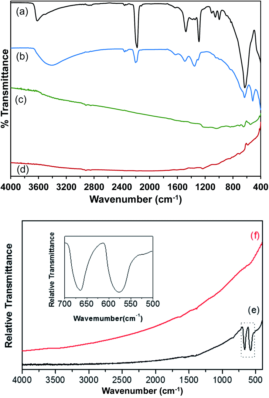 | ||
| Fig. 4 Attenuated Total Reflectance Fourier-Transform Infrared spectra (ATR-FT-IR) of (a) Co(OH)2; (b) Co(OH)2:Ir; (c) Co–Ir; and (d) CoIr-CL; transmission Fourier-transform infrared spectra (FT-IR) of (e) Co–Ir; and (f) CoIr-CL obtained using KBr pellets; inset shows a magnification of the absorption bands at 670 cm−1 and at 578 cm−1 of Co–Ir. | ||
A prior study of α-hydroxides, including those of cobalt and nickel, supports that the materials generally contain a significant amount of intercalated anions.61 Within the ATR-FT-IR spectrum of Co(OH)2 nanosheets, Fig. 4a, surface and intercalated nitrates were assigned to the absorptions at 1381, 1345, 997, and 829 cm−1.50,52,56,57,60,63,64 The nitrate absorptions at 1381, 1345, and 829 cm−1 correspond to free NO3− ions with D3h point group symmetry.48,53,67 Upon coordination to a metal, the local symmetry of the NO3− is lowered to a C2v symmetry.68,69 The remaining nitrate absorption at 997 cm−1 is assigned to coordinated NO3− ions in the Co(OH)2 structure with C2v symmetry.65 The presence of nitrate absorptions in the ATR-FT-IR spectra of the as-prepared Co(OH)2 nanosheets suggests that NO3− from Co(NO3)2·6H2O is carried through the synthesis procedure and exists in two different environments within the material.64 The ν1 mode of NO3− is usually IR-inactive; however, the presence of intercalated water between the Co(OH)2 nanosheets could result in a NO3− environment in which the ν1 mode of NO3− becomes weakly IR-active.64 The presence of free CO32− ions with D3h point group symmetry is indicated by absorptions at 1478 and 889 cm−1.50,52,68 The presence of carbonate within the sample could result from the dissolution of CO2 in the aqueous solutions prior to urea hydrolysis. In addition, carbonate anions could be generated by the decomposition of urea, as previously proposed.47
The ATR-FT-IR spectrum of Co(OH)2:Ir is shown in Fig. 4b. Following iridium deposition onto the Co(OH)2 nanosheets, changes to the Co(OH)2 spectrum are observed. The δ(Co–O–H) peak is shifted to 632 cm−1 while a new peak with greater relative intensity appears at 510 cm−1 in the Co(OH)2:Ir spectrum. Bands for carbonate and nitrate ν3 modes were blue shifted to 1495 and 1365 cm−1 respectively. Absorptions at 3417 and 1627 cm−1 indicate the presence of surface or interlayer water. The Co–O–H deformation and Co–O stretch of Co(OH)2 are assigned to the absorptions at 633 and 401 cm−1, respectively. The absorption at 515 cm−1 is in the range of bands observed for ν(Ir–O)70 and ν(Co–O)71 modes; and further analysis is needed to determine the specific assignment of this band within Co(OH)2:Ir.
The remaining absorptions in the Co(OH)2:Ir spectrum are associated with surface and interlayer species that are present in the as-prepared Co(OH)2 precursor. The 2201 cm−1 absorption is attributed to the asymmetric OCN− stretch. The presence of free NO3− ions was determined based on the 1354 and 828 cm−1 absorptions. The absorption at 1493 cm−1 is assigned to the ν3 mode of CO32−.52 The O–H deformation and C–O stretching modes at 1303 and 1040 cm−1, respectively,66 support the presence of residual ethylene glycol within Co(OH)2:Ir. The nitrogen species band is blue shifted to 2200 cm−1 and is greatly reduced in intensity following iridium deposition. Broadening and red shifting of the ν(O–H) band, as well as increased relative intensity of the δ(H2O) band, suggest incorporation of more water molecules into the structure during the deposition process. Broadening and shifting of the ν(O–H) bands is consistent with increased hydrogen bonding within the structure.54 The reduction in the relative intensity of bands arising from ethylene glycol between the spectrum of Co(OH)2 and Co(OH)2:Ir suggests that it is possible that ethylene glycol may act as a reducing agent to reduce Ir3+ to Ir during the deposition process as supported by prior work on formation of colloidal Ir and other platinum-group metal nanoparticles,42,43 or alternatively ethylene glycol is removed during the Ir deposition process; however, further analysis is needed to determine the potential role of ethylene glycol during the deposition process.
Fig. 4c shows the ATR-FT-IR spectrum of a Co–Ir sample following a thermal treatment at 300 °C of Co(OH)2:Ir for 20 minutes. The ATR spectrum of the resulting black solid indicated that the sample strongly absorbed the infrared radiation and possessed a highly metallic character. Dehydration of the sample was apparent by the lack of water related absorptions. The effect of scattering of the infrared radiation by the Co–Ir sample is apparent by the sloping baseline. For strongly absorbing samples, light scattering within the sample causes the baseline to slope upwards with increasing wavenumbers.72 The ATR spectrum of the CoIr-CL sample following chemical leaching of the cobalt, Fig. 4d, also indicated the presence of a highly metallic phase.70
Since the ATR spectra of Co–Ir and CoIr-CL did not show clearly resolved bands relative to the baseline consistent with their metallic character as described above, transmission FT-IR measurements of samples within potassium bromide (KBr) pellets were made. Shown in Fig. 4e and (f) are the transmission FT-IR spectra of Co–Ir and CoIr-CL, respectively. The FT-IR spectrum of Co–Ir (Fig. 4e) has only two defined peaks at 670 and 578 cm−1 whose wavenumbers are generally consistent with the positions of bands from Co3O4 modes based on a prior study that reported two distinct and sharp bands at 568 (ν1) and 664 (ν2) cm−1 which originate from the stretching vibrations of the Co–O bonds within spinel Co3O4.71 The ν1 band is characteristic of a Co3+–O vibration in an octahedral site, and the ν2 band is attributed to a Co2+–O vibration in a tetrahedral site in the spinel lattice.73 Our X-ray diffraction data showed the presence of peaks consistent with Co3O4. It is also possible that the 578 cm−1 band originated from a Ir–O stretching mode based on a prior study;70 however, our X-ray diffraction data did not show the presence of any IrOx phase.
Scanning transmission electron microscopy characterization
High-angular dark-field scanning transmission electron microscopy (HAADF-STEM) images of CoIr-CL after chemical leaching were obtained to evaluate the atomic-level structure (Fig. 5). The low magnification STEM image (Fig. 5A) confirmed the existence of extended 2D framework created by the highly porous network of interconnected short nanofilaments. From nitrogen physisorption analysis, our group reported that the majority of pores within CoIr-CL nanoframes are within the 2–50 nm (mesopore) and >50 nm (macropore) range.35 The porous network within CoIr-CL may play an important role in mass transport processes since in particular mesopores (2–50 nm) within the structure facilitate reactant/product mass transport to the active catalyst sites.37,74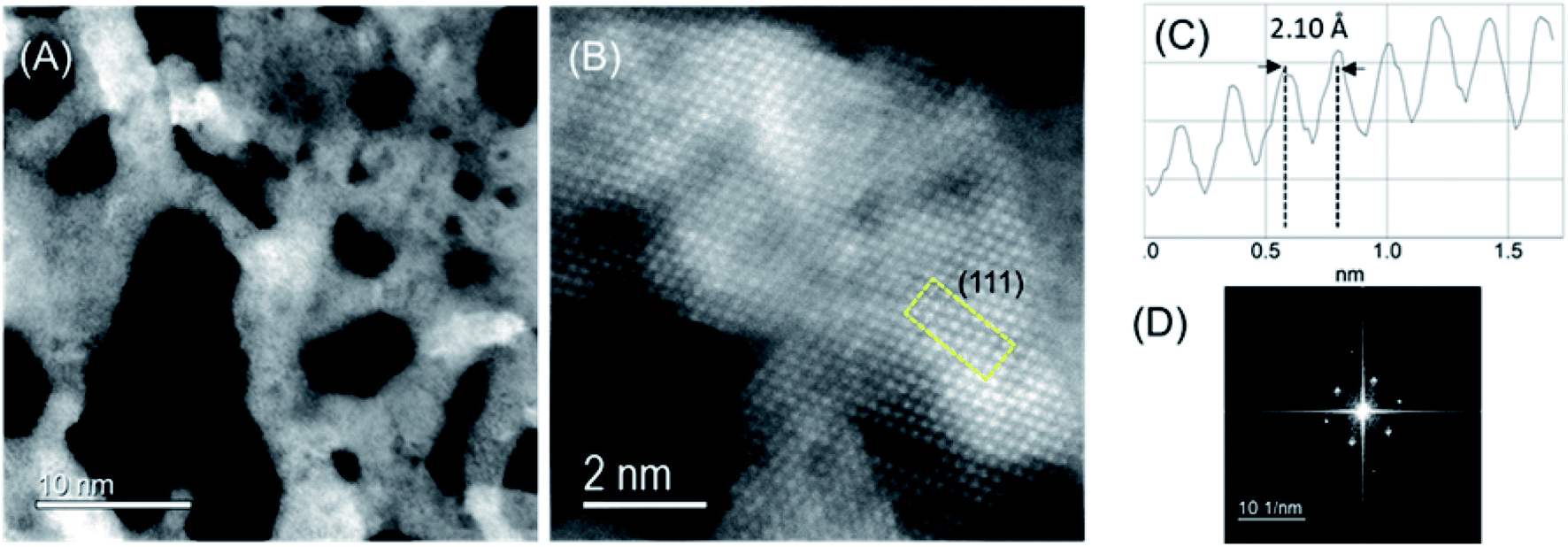 | ||
| Fig. 5 Low-magnification (A) and high resolution (B) high-angular dark-field scanning transmission electron microscopy (HAADF-STEM) images of CoIr-CL catalyst. The yellow box in (B) indicates the area used for the HAADF-STEM intensity profile shown in (C) which shows an interplanar distance consistent with (111) lattice plane; (D) fast Fourier transform (FFT) of the boxed area in yellow in (B). | ||
The high-resolution HAADF-STEM image (Fig. 5B) and fast Fourier transform (FFT) pattern (Fig. 5D) demonstrate the single-crystalline nature of domains within the material. The intensity profile (Fig. 4C) shows an average lattice spacing of 0.213 ± 0.009 nm corresponding to the (111) lattice plane of bimetallic CoIr-CL, according to a face-centered cubic (fcc) structure identified by XRD (Fig. 3), and confirmed a lattice compression with respect to the metallic iridium pattern taken as the standard (0.216 nm).35 The HAADF-STEM and corresponding EDS mapping images of CoIr-CL (Fig. S2†) show uniformly dispersed Co and Ir, consistent with the XRD data. The elemental composition of Ir, Co, and O from HAADF-STEM EDS is in a similar range as values obtained from SEM EDS analysis (Fig. 2).
Characterization of the surface region using X-ray photoelectron spectroscopy
X-ray photoelectron spectroscopy (XPS) was used to identify and perform semi-quantitative analysis of chemical species within the surface region of the catalyst materials. A comparison of the average survey spectra acquired from the surfaces of commercial IrO2 and CoIr-CL is shown in Fig. S3.† For both samples, iridium, chlorine, carbon, nitrogen, oxygen and sodium core-level peaks were clearly observed and identified (sodium peak not shown). In addition to iridium, cobalt, and oxygen, the presence of carbon, chlorine, nitrogen, and sodium within the samples was observed and is attributed to the precursors used during the synthesis process. As expected, the cobalt core-level peak was only observed in the CoIr-CL material.Semi-quantitative analysis of the XPS average survey spectra was used to estimate the atomic composition within the surface region (Table 1). Analysis of the survey spectra of CoIr-CL and IrO2 supports that a higher degree of oxygen is present within the surface region of IrO2 (52.3 atomic% oxygen) compared to CoIr-CL (33.3 atomic% oxygen). The weight percentages of Ir, Co and O within the surface region determined from XPS are in general agreement with values obtained from SEM-EDS analysis (Fig. 2I–L); however, XPS analysis showed a slightly lower surface concentration of Ir and a slightly higher concentration of O and Co species compared to SEM-EDS analysis (Table S1†) which may be due to differences in probing of the surface region between these methods.
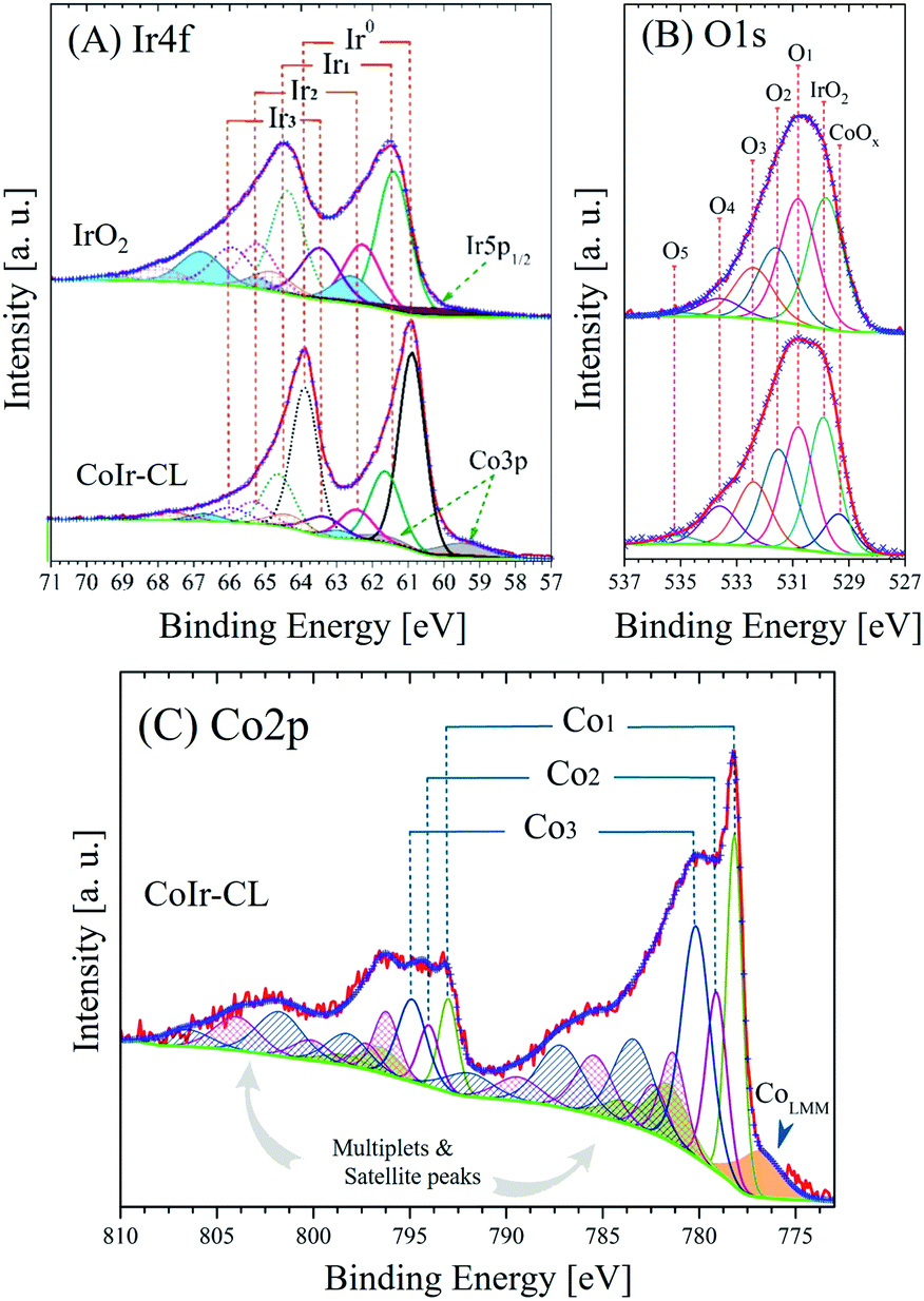 | ||
| Fig. 6 High-resolution X-ray photoelectron spectra and fitted peaks of (A) Ir4f and (B) O1s regions of commercial IrO2 and CoIr-CL samples and (C) Co2p region of CoIr-CL; the intensities of Ir4f and O1s core level spectra were normalized; details of peak fitting analysis and label are discussed in the text and in Table 2. | ||
| Region | Sample | BE [±0.1 eV] | FWHM [eV] | Areaa [at%] | Label | Assignment |
|---|---|---|---|---|---|---|
| a Average content of six points. | ||||||
| Ir4f | IrO2 | ≈60.8 | 4.2 | 43.2 | Ir5p1/2 | Metal, oxide and hydroxide range |
| 61.4 | 1.1 | 29.8 | Ir1 | IrO2 | ||
| 62.3 | 1.2 | 14.2 | Ir2 | Ir2O3, IrCl3·xH2O, IrClx and/or IrCl3 | ||
| 62.6 | 1.2 | — | — | Ir(IV) Sat I | ||
| 66.6 | 1.3 | — | — | Ir(IV) Sat II | ||
| 63.5 | 1.3 | 12.8 | Ir3 | Hydrous IrO2, Ir(OH)3 | ||
| 64.7 | 1.4 | — | — | Ir(III) Sat | ||
| CoIr-CL | 60.9 | 3.5 | 33.8 | Ir5p1/2 | Metal, oxide and hydroxide range | |
| 59.6 | 1.7 | 23.8 | Co3p | Metal, oxide and hydroxide range | ||
| 60.9 | 0.9 | 24.3 | Ir0 | Metallic iridium | ||
| 61.6 | 1.1 | 10.5 | Ir1 | IrO2 | ||
| 62.5 | 1.2 | 4.2 | Ir2 | Ir2O3, IrCl3·xH2O, IrClx and/or IrCl3 | ||
| 62.9 | 1.0 | — | — | Ir(IV) Sat I | ||
| 66.8 | 1.1 | — | — | Ir(IV) Sat II | ||
| 63.4 | 1.3 | 3.4 | Ir3 | Hydrous IrO2, Ir(OH)3 | ||
| 64.8 | 1.4 | — | — | Ir(III) Sat | ||
| O1s | IrO2 | 529.8 | 1.55 | 32.4 | IrO2 | IrO2 |
| 530.8 | 1.56 | 27.9 | O1 | Ir2O3, Mx(CO3)y | ||
| 531.6 | 1.63 | 19.8 | O2 | Ir(OH)3, IrO(OH)2 | ||
| 532.4 | 1.70 | 13.7 | O3 | IrCl3·xH2O, ClO3−, C–OH, C–O–C | ||
| 533.6 | 1.78 | 5.0 | O4 | NO3−, O![[double bond, length as m-dash]](https://www.rsc.org/images/entities/char_e001.gif) C–O, OH ads. species C–O, OH ads. species |
||
| 534.9 | 1.85 | 1.1 | O5 | –COO–, OC–O, adsorbate |
||
| CoIr-CL | 529.4 | 1.33 | 7.5 | CoOx | CoO, Co3O4 | |
| 529.9 | 1.34 | 25.8 | IrO2 | IrO2 | ||
| 530.9 | 1.40 | 23.9 | O1 | Ir2O3, Mx(CO3)y | ||
| 531.5 | 1.47 | 17.5 | O2 | Ir(OH)3, IrO(OH)2 | ||
| 532.3 | 1.53 | 14.5 | O3 | IrCl3·xH2O, ClO3−, C–OH, C–O–C | ||
| 533.6 | 1.60 | 8.9 | O4 | NO3−, OC–O, OH ads. species |
||
| 535.2 | 1.66 | 1.9 | O5 | –COO–, OC–O, adsorbate |
||
| Co2p | CoIr-CL | 776.9 | 2.75 | 7.1 | Co LMM | Co Auger L3M23M45 transition |
| 778.2 | 1.02 | 35.8 | Co1 | Metallic cobalt | ||
| 781.6 | 2.52 | — | — | 1st metallic cobalt satellite | ||
| 783.8 | 2.77 | — | — | 2nd metallic cobalt satellite | ||
| 779.1 | 1.29 | 21.8 | Co2 | Co3O4 | ||
| 781.3 | 1.67 | — | — | 1st Co3O4 multiplet | ||
| 782.4 | 1.77 | — | — | 2nd Co3O4 multiplet | ||
| 785.5 | 2.44 | — | — | 1st Co3O satellite | ||
| 789.5 | 2.91 | — | — | 2nd Co3O satellite | ||
| 780.2 | 1.80 | 35.3 | Co3 | Co(OH)2, CoOOH, CoO | ||
| 783.4 | 2.69 | — | — | 1st Co(OH)2 multiplet | ||
| 787.2 | 2.98 | — | — | 1st Co(OH)2 satellite | ||
| 791.8 | 3.23 | — | — | 2nd Co(OH)2 satellite | ||
Surface characterization using cyclic voltammetry and carbon monoxide stripping voltammetry
The CoIr-CL and IrO2 catalysts were electrochemically analyzed using a thin-film rotating disk electrode technique.82 Cyclic voltammetry (CV) of CoIr-CL was used to characterize the initial catalyst surface and the evolution of the surface following an electrochemical oxidation protocol (Fig. 7). After initial conditioning by cycling at low potential range (E ≤ 1.0 VRHE) in O2-free 0.1 M HClO4, the CoIr-CL catalyst (Fig. 7A, black curve) exhibited distinctive hydrogen adsorption/desorption features associated with hydrogen underpotential deposition (Hupd) on a metallic Ir surface.83 No peak associated with the oxidation of the non-noble species (i.e. Co) was observed during the first cycle,84 corroborating the formation of a stable metallic Ir-rich surface after the chemical leaching step. The presence of metallic surface features is consistent with the metallic phase observed from STEM and XPS measurements (Fig. 5 and 6A). In addition, oxidation/reduction peaks due to reversible IrOx formation/reduction at E ≥ 0.5 VRHE were also observed.83 Carbon monoxide (CO) stripping voltammetry measurements (Fig. 7B) also support the presence of a metallic Ir-rich surface on the CoIr-CL material. From the integration of the CO stripping peak, the calculated electrochemical surface area of Ir (ECSAIr,CO) was 61.2 ± 3.1 m2 g−1 which is comparable with the BET surface area of CoIr-CL of 57 ± 7 m2 g−1 previously reported by our group,35 supporting a high dispersion of Ir on the surface. In addition, the electrochemical surface area of CoIr-CL is reasonably high compared to the electrochemical surface area of commercial IrO2 (Alfa Aesar) of 25.3–28.7 m2 g−1 determined by pseudocapacitance and mercury underpotential deposition measurements.14,85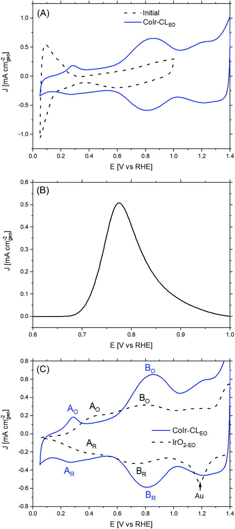 | ||
| Fig. 7 (A) Cyclic voltammograms of CoIr-CL (dashed black line) and CoIr-CLEO, after electrochemical oxidation, (solid blue line); (B) carbon monoxide (CO) stripping voltammetry of CoIr-CL; and (C) comparison of cyclic voltammograms of CoIr-CLEO and IrO2-EO; peaks A and B are notated as oxidation (labelled with subscript “O”) or reduction (labelled with subscript “R”) peaks; details provided in the text. | ||
Similar to as observed within our prior work on NiIr nanoframes,14 the CoIr-CL catalyst showed that the predominantly metallic nature of the surface of the electrocatalyst was altered after cycling to potentials required for OER, modifying the surface functional groups. Therefore, in order to have obtain a representative surface structure upon which the OER reaction takes place, an “electrochemical oxidation” step (notated with an “EO” subscript) comprising 60 scans between 0.05–1.5 VRHE, was carried out with the CoIr-CL and IrO2 catalysts. The catalyst after the EO step is labelled as CoIr-CLEO (Fig. 7A, blue curve). After electrochemical oxidation, the peaks due to Hupd features were no longer observed, instead, two broad anodic peaks around 0.27 VRHE and 0.82 VRHE assigned to iridium hydroxide/oxide surface features were present.83 The CVs of CoIr-CLEO and IrO2-EO are compared in Fig. 7C. Within IrO2,EO, the anodic peak at ∼0.48 VRHE (labeled A0) has been attributed to formation of iridium(III) hydroxide86 and modelled as involving the oxidation of two Ir3+–OH2 groups to two Ir4+–OH groups,87 while the peak at ∼0.81 V (labeled B0) has been attributed to oxidation of iridium(III) hydroxide to tetravalent IrO2 or IrO(OH)2.86,88 Compared with the CV of IrO2-EO, the CV of CoIr-CLEO showed the anodic peak, A0, at a significantly lower potential of ∼0.27 VRHE compared to the voltage of the peak at IrO2-EO (∼0.48 VRHE) which suggests different local chemical environments for hydrated Ir–OH species at the surface of CoIr-CLEO and IrO2-EO.
Since the surface of CoIr-CLEO was no longer metallic after the electrochemical oxidation step, we used pseudocapacitance measurements (Fig. S8†) and previously reported parameters and conversion factors37 to determine the ECSA of CoIr-CLEO (Table S5†). The ECSAIrO2 of CoIr-CLEO determined from pseudocapacitance measurements was calculated to be 30 ± 5 m2 g−1 which is much lower than the ECSAIr value determined from CO stripping (61.2 ± 3.1 m2 g−1) obtained before electrochemical oxidation, but very similar to the surface area estimated for IrO2-EO. The growth of the oxide/hydroxide surface species during the electrochemical oxidation step may result in lowering the surface area by growing within smaller pores and limiting the access of the electrolyte.74,89 Our previous study of NiIr nanoframes showed the presence of a ∼5 Å-thick oxide/hydroxide surface layer after the electrochemical oxidation step.14
Evaluation of electrochemical oxygen evolution activity and reaction mechanism
Following the electrochemical oxidation step, the OER activity of the CoIr-CLEO catalyst material was electrochemically evaluated based on previously reported methods by our group14 and other groups.36 To determine the OER current, we used chronoamperometry rather than linear sweep voltammetry to reduce the contribution of electrochemical double layer capacitance.14 To evaluate the mass activity, the current determined from chronoamperometry was normalized for the actual Ir mass which was calculated by determining the Ir mass on the electrode and subtracting the Ir leached out into the solution during the EO step determined by inductively coupled plasma mass spectrometry (details provided in Experimental section).Shown in Fig. 8A are the chronoamperometric polarization curves of CoIr-CLEO and IrO2,EO normalized versus the mass of Ir. The higher current observed for CoIr-CLEO within the OER chronoamperometric curve clearly shows the superior OER activity of CoIr-CLEO compared to IrO2,EO. The mass-normalized OER activities of the CoIr-CLEO, and IrO2-EO were compared at 1.51 VRHE and are shown in Fig. 8C. A potential of 1.51 VRHE was used since the Tafel plot (Fig. 8B) still shows linear behavior within this voltage region, and lower overpotential relative to the thermodynamic potential of the reaction also minimizes the contribution of mass transport. At a potential of 1.51 VRHE, the mass activity of CoIr-CLEO (243 ± 47 A gIr−1) is 17 times higher than the mass activity of IrO2-EO (13.9 ± 1.4 A gIr−1).
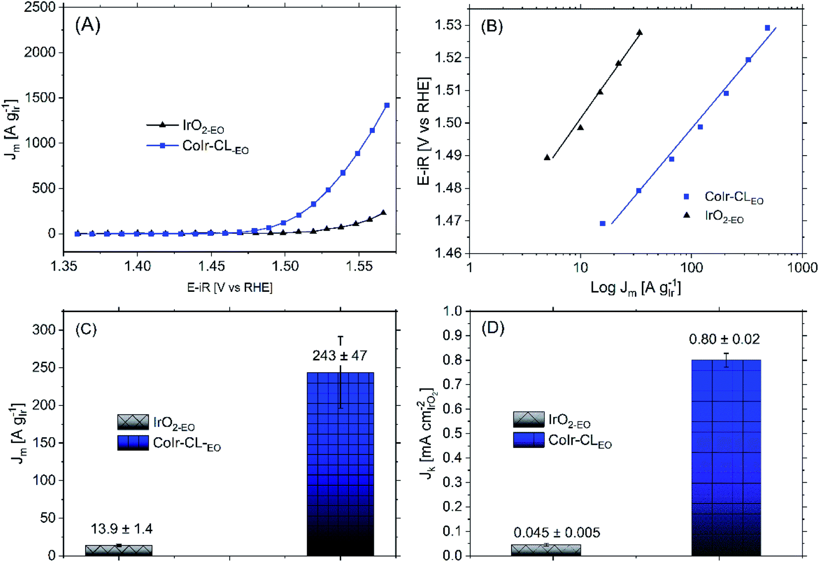 | ||
| Fig. 8 (A) Current in the oxygen evolution reaction (OER) voltage region determined from chronoamperometry measurements of CoIr-CL 2D nanoframes and commercial IrO2 after electrochemical oxidation (EO) step; testing performed in O2-free 0.1 M HClO4 under rotation at 2500 rpm; (B) Tafel plot and fitted Tafel slopes obtained from chronoamperometry data; the potential (iR-corrected) was set between 1.47 V to 1.52 V to reduce the mass transport contribution; (C) comparison of OER mass activities at 1.51 VRHE; and (D) comparison of OER specific activities at 1.51 VRHE. | ||
We determined the OER specific activity by normalizing the current to the electrochemical surface area determined from pseudocapacitance measurements. As shown in Fig. 8D, the OER specific activities at 1.51 VRHE is 0.80 ± 0.02 A cmIrO2−2 for CoIr-CLEO which is significantly (18 times) higher than the OER specific activity of 0.045 ± 0.005 A cmIrO2−2 for commercial IrO2 (IrO2-EO). The CoIr-CLEO catalyst showed a significant improvement in both mass and specific OER activity compared with the commercial IrO2-EO catalyst.
The improvement of the specific activity of CoIr-CLEO compared to IrO2-EO indicates that the catalytically active surface sites of CoIr-CLEO are more active for oxygen evolution. Our XPS measurements (Fig. 6) support the presence of multiple species within the surface region including iridium oxide, iridium oxyhydroxide, and iridium hydroxide with iridium in 4+ and 3+ oxidation states and the presence of cobalt oxides and hydroxides with cobalt in 2+ and 3+ oxidation states. However, our CV data (Fig. 7C) shows that the surface is changed after undergoing exposure to high oxidation potentials under OER conditions, and therefore the CV measurements are more representative of the OER catalyst surface. The CV of CoIr-CLEO (Fig. 7C) shows peaks consistent with the surface having Ir3+–OH and Ir4+O2 or Ir4+O(OH)2 groups. As discussed above, the potential of the oxidation peak at ∼0.27 VRHE, attributed to surface Ir3+–OH groups occurs at a lower potential compared to the peak potential of ∼0.48 VRHE for IrO2-EO. Prior work supports that iridium hydroxo (Ir–OH) surface species are strongly linked to OER activity,2 and Ir–OH groups can be considered as descriptors for OER activity.90 The higher surface activity of CoIr-CLEO compared to IrO2-EO is attributed to presence of highly active Ir-OH species that may interact with subsurface Co; however, additional analysis is needed to characterize the surface under reaction conditions. The OER in acid involves a complex, multi-step reaction with multiple intermediates (discussed below). A number of prior studies support that at OER potentials the oxidation state of iridium increases from 4+ to 5+,91–93 while other studies report only Ir4+ is present under OER conditions.94–96 The different electronegativity of Co compared to Ir may influence the oxidation states and electron density distribution within one or more of the OER steps and/or intermediates.2,14,90–96 Substituents influence local electron density and affect the OER steps as supported by our previous study that modelled the effect of Ni-substituted into IrO2 and found Ni within specific sites resulted in electron density accumulation within bridging oxygens, lowering the activation energy of the rate-determining OH bond breaking step.14 Prior DFT calculations support that cobalt doping within IrO2 modifies the electronic structure of the active site and lowers the OER activation energy.25 A previous study reported Co incorporation within SrIrO3 increased the coverage of surface hydroxyl groups, modified the Ir–O bond covalency, altered the oxygen p-band center of the material, and increased OER activity.30 We confirmed that cobalt remains within the structure after exposure to OER conditions following durability testing (Fig. S9†); however, additional analysis is needed to determine the specific nature of Co within the surface region after exposure to electrochemical potentials and how Co within IrO2 affects the electron density and OER kinetics.
In addition to direct comparison of the OER activity of CoIr-CLEO with IrO2-EO from our group's tests,14 the OER mass activities of CoIr-CLEO were compared with previously reported Co and Ir based catalysts in Table S6.† A direct comparison is difficult due to differences in the experimental conditions such as the type of electrolyte, electrochemical method (i.e. linear sweep voltammetry or chronoamperometry), catalyst loading, potential of the analysis, ohmic drop correction, background subtraction etc., which can influence the final activity values.14 The CoIr-CLEO nanoframes showed one of the highest OER activities compared to similar CoIr-based materials reported to date only lower than recently reported IrCo nanowires.3 The overpotential of CoIr-CLEO nanoframes was also lower than that of previously reported IrCo oxide materials.27,28
The Tafel slopes of CoIr-CLEO and IrO2,EO (Fig. 8B) were analyzed to provide insight regarding the reaction mechanism.97,98 The Tafel slope of CoIr-CLEO (40 ± 4 mV dec−1) is similar to the Tafel slope of IrO2,EO (44 ± 3 mV dec−1), and consistent with the value of others that report a similar IrOx(OH)y surface structure.99 The similar Tafel slopes of CoIr-CLEO and IrO2-EO suggest that similar rate-determining step is controlling the reaction mechanism on both catalysts. Previous studies on OER mechanisms have proposed different electrochemical pathways including the “electrochemical oxide path” and “DFT-predicted peroxide path”, differentiated by the formation of dissimilar surface intermediate species and recombination steps.100–103 The electrochemical oxide path is described by eqn (1)–(3) below,
| H2O + M → M–OH + H+ + e− | (1) |
| M–OH → M–O + H+ + e− | (2) |
| 2M–O → 2M + O2 | (3) |
| M–O + H2O → MOOH + H+ + e− | (4) |
| MOOH → M + O2 + H+ + e− | (5) |
Within both reaction mechanisms (i.e. electrochemical oxide path and DFT-predicted peroxide path), considering the second proton–electron transfer step as the rate limiting reaction step results in a predicted Tafel slope of 40 mV dec−1.101 The measured values of the Tafel slopes of CoIr-CLEO and IrO2-EO suggest that the OER is limited by the second electron transfer step (eqn (2)) which involves formation of Ir–O species and that the reaction may proceed via either the electrochemical oxide path or DFT-predicted peroxide path. It is important to note that the analysis of the reaction mechanism using the Tafel slope includes the assumption that the relative surface coverage of the adsorbed species is constant.100 Results obtained by microkinetic analysis98 have demonstrated that the evolution of the concentration of intermediates must be considered; therefore, more analysis needs to be done to corroborate the actual mechanism.
Evaluation of electrocatalyst stability
Within acidic OER catalysts, stability remains a critically important but significantly less studied factor relative to activity.18,104 Catalyst degradation and long term performance have an important impact on the development of PEM electrolyzers, particularly with low catalyst loadings.3 The stability of the catalyst was evaluated using an accelerated durability testing (ADT) protocol consisting of applying a constant potential of 1.6 V for 13.5 hours, which has been previously utilized to evaluate the durability of a number of iridium-based catalysts.3,36The comparison of the iridium mass-normalized current, Tafel slopes, OER mass activities, and OER specific activities of CoIr-CLEO and IrO2-EO (after EO) and CoIr-CLADT and IrO2-ADT (after ADT) are presented in Fig. 9A–D. As shown in Fig. 9A, both CoIr-CLEO and IrO2-EO resulted in lower currents after the ADT protocol, which is consistent with prior reports of IrO2 that showed catalyst performance degradation occurs under similar testing conditions.36 The OER mass activity of the commercial IrO2-EO catalyst at 1.51 VRHE decreased from 13.9 to 11.7 A gIr−1 indicating a retention of 84 ± 7% of the initial mass-normalized current, and the OER mass activity of the CoIr-CLEO catalyst decreased from 243 to 192 A gIr−1 indicating a retention of 79 ± 9% of the initial mass-normalized current (Fig. 9C). After the ADT protocol, the specific activity of IrO2-ADT was reduced by ∼7% from 0.045 ± 0.005 mA cmIrO2−2 to 0.042 ± 0.005 mA cmIrO2−2, while the specific activity of CoIr-CLADT slightly increased (∼4%) from 0.80 ± 0.02 mA cmIrO2−2 to 0.83 ± 0.08 mA cmIrO2−2, (Fig. 9D). The analysis of the Tafel slopes of CoIr-CLEO and IrO2-EO before and after ADT (Fig. 9B) suggests that the reaction mechanism and possibly the nature of active sites on the surface remain similar. As explained above, it is likely that the second electron transfer remains the rate determining step before and after ADT; however, more studies are needed to support the specific reaction mechanism.
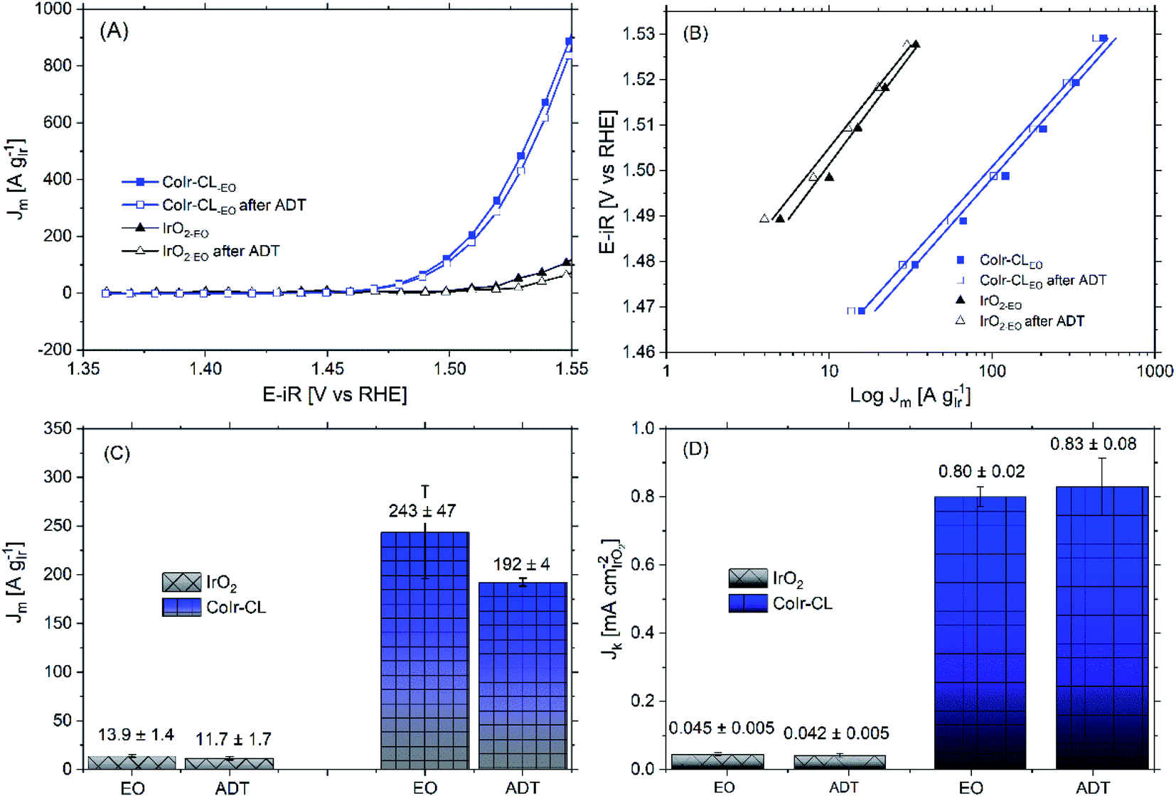 | ||
| Fig. 9 (A) Current in the oxygen evolution reaction (OER) voltage region determined from chronoamperometry measurements of CoIr-CL 2D nanoframes and commercial IrO2 before and after accelerated durability testing in O2-free 0.1 M HClO4. The stability was carried out using a potentiostatic procedure by holding the working electrode at 1.6 VRHE-iR-corrected for 13.5 hours under rotation at 2500 rpm; (B) Tafel plot and Tafel slopes before and after accelerated durability testing determined by chronoamperometry; the potential (iR-corrected) was set between 1.47 V to 1.52 V to minimize the mass transport contribution; (C) comparison of OER mass activities at 1.51 VRHE before and after accelerated durability testing; (D) comparison of OER specific activities at 1.51 VRHE before and after accelerated durability testing. | ||
To gain insight into the electrochemical stability, understand the intrinsic relationship between mass and specific activity within CoIr-CLADT and IrO2-ADT, and evaluate the relative contributions of different factors involved in the degradation process, we further compared the surface structure, morphology, and iridium and cobalt dissolution over the ADT protocol. The mass and specific activity are related, and the relationship can be described by eqn (6),105
 | (6) |
To understand factors contributing to the increase in specific activity for CoIr-CLADT and the decrease in specific activity for IrO2-ADT, we first analyzed the evolution of the surface of the CoIr-CL and IrO2 catalysts before and after ADT by CV (Fig. S8†). In general, the CVs of the catalysts after EO and after ADT showed qualitatively similar profiles, suggesting that the surface chemical environment remained unchanged. However, the decrease in the coulombic charge after ADT is associated to the loss of electrochemically active surface sites, either associated to dissolution of Ir or particle agglomeration. Changes in the morphology and agglomeration were demonstrated by microscopy after ADT (Fig. S9†), and the iridium dissolution rate was determined by analyzing the concentration of Ir within the electrolyte solution after EO and ADT protocols, as discussed below.
The similarities of the Tafel slopes (Fig. 9B) and cyclic voltammograms (Fig. S8†) obtained before and after ADT discredits the idea that the changes on the nature of active sites or the reaction mechanism are primarily responsible for modifying the specific activity of CoIr-CL. Upon further examination although qualitatively the electroactive species observed within the CV seem to be the same, the relative charge of the electroactive species was determined to be different after ADT. Considering that the oxidation peak, Ao, is intimately related to the presence of highly active sites of Ir3+–OH species, which have been taken as experimental descriptors toward increasing specific activity,90 the changes of the number of these surface species are an important factor. The fitting of the CV curves allowed the quantification of the relative charge associated to the different surface species (i.e. Ir3+–OH species,2 and Ir3+ to Ir4+ species within an oxide structure87,88). The analysis of the relative ratio of coulombic charge of oxidation peaks Ao/Bo decreased from 0.12 to 0.097 for IrO2-ADT but increased from 0.05 to 0.085 for CoIr-CLADT (Fig. S8†). The reduction of highly active Ir3+–OH species may be responsible for the reduction of activity of IrO2-ADT, and the increase of Ir3+–OH species may be responsible for improving of the specific activity of CoIr-CLADT. Additional analysis is needed to consider other factors (e.g. conductivity, etc.).
The OER mass activity is intimately related to the OER specific activity, but also to the number of iridium active sites available for the reaction, as described in eqn (6). Therefore, changes of specific activity and/or ECSA, caused by Ir dissolution or changes of morphology among other factors will affect mass activity. The OER mass activity of the commercial IrO2-EO catalyst at 1.51 VRHE decreased from 13.9 to 11.7 A gIr−1 (Fig. 9A and C). The average decrease of mass activity in IrO2-ADT can be explained by the combined contribution of lower specific activity (∼7%) and partial dissolution of Ir as discussed below.
After the ADT protocol, the OER mass activity of the CoIr-CLEO catalyst at 1.51 VRHE decreased from 243 to 192 A gIr−1 resulting in a relative stability of 79 ± 9%, which is within experimental error of the value of the commercial IrO2 catalyst. However, at higher potential of 1.55 VRHE (Table S5†), the mass activity retention of CoIr-CLEO was 94 ± 2%. In contrast the IrO2-EO catalyst showed a relative retention of mass activity at 1.55 VRHE which was lower (66 ± 9%) but within experimental error of the value at 1.51 VRHE (77 ± 7%) (Table S5†). The mass transport issues become more relevant at higher current densities due to the inability to remove reaction products fast enough.38 The improved retention of mass activity at higher voltages for the CoIr-CLEO catalyst compared with commercial IrO2 may also represent an important advantage in practical electrolyzer cells that operate at higher current densities and voltages. The post-mortem SEM analysis of the CoIr-CLADT (Fig. S9†) showed the presence of cobalt, the retention of 2D-structure, and the existence of additional morphologies that included small nanoparticles. We consider that the ability of CoIr-CLEO to maintain high activity after durability testing may result from the combination of (i) retention of the high specific surface activity by the presence of highly active surface functional groups and (ii) the partial retention of the integrated nanostructured morphology.
Multiple studies have shown that iridium dissolution occurs under the highly oxidative potentials and highly acidic conditions used for acidic oxygen evolution.19,20,83 The Ir dissolution rate is also affected by the presence of non-noble metals (i.e. Co, Ni etc.) within the structure as well as the experimental processes used during the electrochemical conditioning and testing of the electrode.3,12,14 To gain more insight into the degradation processes, we analyzed the Ir dissolution rates of IrO2 and Ir and Co cobalt dissolution rates of CoIr-CL, both after EO and after ADT using ICP-MS analysis, and the results are summarized in Table 3. Significant differences between the dissolution rates are observed between IrO2 and CoIr-CL and between the EO and ADT steps. For IrO2, the EO protocol resulted in an Ir dissolution rate of 2.4 pgIr cm−2 s−1 and barely contributed to the dissolution of Ir from IrO2 giving only 1.1 ± 0.1 wt%.14 This result is in line with the constant CV profile observed before and after EO for commercial IrO2 (data not shown). The ADT protocol resulted in a higher Ir dissolution rate of 27.8 ± 1.6 pgIr cm−2 s−1 for IrO2-ADT. The dissolution of Ir has been shown to be potential-dependent,83 and the different Ir dissolution rates of IrO2 for EO and ADT steps may result from the different protocols that involve either potential sweeps (EO step) or constant potentials (ADT).
| IrO2 | CoIr-CL | ||||
|---|---|---|---|---|---|
| Mass loading (μgIr cmgeo−2) | Ir dissolution rate (pgIr cm−2 s−1) | Mass loading (μgIr cmgeo−2) | Ir dissolution rate (pgIr cm−2 s−1) | Co dissolution rate (pgCo cm−2 s−1) | |
| a Value estimated from previous report.14 | |||||
| Initial | 11.6 | — | 15.3 | — | |
| EO | 11.6 | 2.4a | 13.7 | 997 ± 470 | 2990 ± 250 |
| ADT | 10.5 | 27.8 ± 1.6 | 11.0 | 66 ± 23 | 4 ± 3 |
For the CoIr-CLEO catalyst, the EO step involves a high rate of Ir dissolution (997 ± 470 pgIr cm−2 s−1) and Co dissolution (2990 ± 250 pgCo cm−2 s−1) into the solution (Table 3) which can be explained by the significant surface reorganization involved in the EO step that transforms the initially metallic surface to an oxide/hydroxide surface (Fig. 7A). It is possible that the Ir and Co dissolution during the EO step may contribute to the generation of highly active Ir–OH groups. A previous study reported leaching of nickel from Ir–Ni oxide thin films resulted in formation of highly active Ir–OH surface sites.12 The higher dissolution rate of Ir within CoIr-CLEO compared to IrO2-EO is consistent with our prior study of hydrous nickel–iridium oxide OER catalysts where presence of Ni increased the dissolution of iridium compared to IrO2.14 CoIr-CLADT showed a significant reduction of the iridium corrosion rate to 66 ± 23 pgIr cm−2 s−1 compared to the value after the EO step (997 ± 470 pgIr cm−2 s−1). After the significant surface reorganization and dissolution involved in the potential sweeps of the EO step of CoIr-CL, the catalyst surface may then become passivated resulting in lower dissolution of Ir and Co over the ADT step, which is supported by the comparison of the CVs for the EO step and ADT step (Fig. S8†). However, the iridium corrosion rate for CoIr-CLADT still showed a ∼2 times higher dissolution rate compared to IrO2-ADT.
The comparison of the electrochemical stabilities of CoIr-CL and IrO2 shows significantly different degradation processes occur for these materials. While from an application perspective additional work is needed to further reduce Ir dissolution rate, despite the higher iridium dissolution of CoIr-CLADT, the increase in the relative concentration of surface Ir–OH groups and the presence of Co within the sublayers resulted in an increase of the specific activity and the retention of OER mass activities compared with IrO2.
Conclusions
Cobalt–iridium two-dimensional nanoframes were synthesized by thermal reduction of iridium-decorated cobalt hydroxide nanosheets followed by a chemical leaching step in acid. The synthesis process resulted in interconnected Co–Ir alloy domains within an unsupported, carbon-free porous nanostructure that allows three-dimensional molecular access to the catalytically active surface sites. After electrochemical conditioning within the OER potential range, the predominately bimetallic alloy surface was transformed to oxide/hydroxide surface. Oxygen evolution activities determined using rotating disk electrode configuration showed that hydrous Co–Ir oxide nanoframes showed 17 times higher OER mass activity and 18 times higher OER specific activity compared with commercial IrO2. The higher OER activities are attributed to the presence of highly active iridium hydroxide surface species within the hydrous Co–Ir oxide surface and subsurface Co–Ir alloy that tunes the surface atomic and electronic structure. CV measurements show the presence of an anodic iridium hydroxide peak at lower potential compared with IrO2 which supports the Co–Ir nanoframes have highly active Ir–OH surface species that may contribute to the high OER activity.In addition to higher activity, the hydrous Co–Ir oxide nanoframes exhibited similar retention of initial OER mass activity (79 ± 9% retention) as commercial IrO2 (84 ± 7% retention) tested with rotating disk electrode measurements using an accelerated durability testing protocol. The retention of OER mass activity over accelerated durability testing of cobalt-containing Co–Ir nanoframes was dramatically higher than similarly prepared nickel-containing Ni–Ir nanoframes14 which suggests cobalt–iridium interaction may be more stable than nickel–iridium interaction within these structures. The comparison of the factors influencing the electrochemical stabilities of CoIr-CL and IrO2 under OER conditions indicates that the catalysts undergo significantly different degradation processes. The decrease in the OER mass activity of the IrO2 catalyst can be explained by the combined contribution of lower specific activity and partial dissolution of Ir. The analysis of the degradation of hydrous Co–Ir oxide nanoframes showed a higher Ir dissolution rate for the compared with IrO2; however, the specific activity of CoIr-CLEO and the relative contribution of surface iridium hydroxide groups increased which contributes to the similar OER mass stability of CoIr-CLEO compared with IrO2 under the ADT testing conditions. Our work that shows that the bimetallic cobalt–iridium 2D nanoframes obtain a significantly higher OER mass activity and similar stability compared with a commercial benchmark IrO2; however, the bimetallic Co–Ir catalyst undergoes a significantly different degradation process compared with the monometallic IrO2 catalyst. Our work furthers the understanding of factors influencing the activity and stability of bimetallic and monometallic acidic OER electrocatalysts and contributes to the design of electrocatalysts with high activity and stability.
Conflicts of interest
There are no conflicts to declare.Acknowledgements
The authors acknowledge support of this research from the Office of Naval Research Grant No. N00014-16-1-2777 and N00014-19-1-2071 for materials, structural and electrochemical characterization. The authors acknowledge support of this research from the National Science Foundation Award No. 1936458 for stability and dissolution analysis. R. M. acknowledges support from the National Science Foundation Research Experiences for Undergraduates (REU) Award, Grant No. 1757843. The authors would like to thank Dr Sanmathi Chavalmane Subbenaik (Washington University in Saint Louis) for her assistance in obtaining ICP-MS analysis.References
- M. Carmo, D. L. Fritz, J. Mergel and D. Stolten, A Comprehensive Review on PEM Water Electrolysis, Int. J. Hydrogen Energy, 2013, 38, 4901–4934 CrossRef CAS.
- D. F. Abbott, D. Lebedev, K. Waltar, M. Povia, M. Nachtegaal, E. Fabbri, C. Copéret and T. J. Schmidt, Iridium Oxide for the Oxygen Evolution Reaction: Correlation between Particle Size, Morphology, and the Surface Hydroxo Layer from Operando XAS, Chem. Mater., 2016, 28, 6591–6604 CrossRef CAS.
- S. M. Alia, S. Shulda, C. Ngo, S. Pylypenko and B. S. Pivovar, Iridium-Based Nanowires as Highly Active, Oxygen Evolution Reaction Electrocatalysts, ACS Catal., 2018, 8, 2111–2120 CrossRef CAS.
- T. J. Meyer, The Art of Splitting Water, Nature, 2008, 451, 778 CrossRef CAS.
- N. Danilovic, R. Subbaraman, K.-C. Chang, S. H. Chang, Y. J. Kang, J. Snyder, A. P. Paulikas, D. Strmcnik, Y.-T. Kim, D. Myers, V. R. Stamenkovic and N. M. Markovic, Activity–Stability Trends for the Oxygen Evolution Reaction on Monometallic Oxides in Acidic Environments, J. Phys. Chem. Lett., 2014, 5, 2474–2478 CrossRef CAS.
- M. H. Miles and M. A. Thomason, Periodic Variations of Overvoltages for Water Electrolysis in Acid Solutions from Cyclic Voltammetric Studies, J. Electrochem. Soc., 1976, 123, 1459–1461 CrossRef CAS.
- T. Reier, M. Oezaslan and P. Strasser, Electrocatalytic Oxygen Evolution Reaction (OER) on Ru, Ir, and Pt Catalysts: A Comparative Study of Nanoparticles and Bulk Materials, ACS Catal., 2012, 2, 1765–1772 CrossRef CAS.
- S. Hackwood, L. M. Schiavone, W. C. Dautremont-Smith and G. Beni, Anodic Evolution of Oxygen on Sputtered Iridium Oxide Films, J. Electrochem. Soc., 1981, 128, 2569–2573 CrossRef CAS.
- H. R. Yu, N. Danilovic, Y. Wang, W. Willis, A. Poozhikunnath, L. Bonville, C. Capuano, K. Ayers and R. Maric, Nano-size IrOx Catalyst of High Activity and Stability in PEM Water Electrolyzer with Ultra-low Iridium Loading, Appl. Catal., B, 2018, 239, 133–146 CrossRef CAS.
- S. Zhao, A. Stocks, B. Rasimick, K. More and H. Xu, Highly Active, Durable Dispersed Iridium Nanocatalysts for PEM Water Electrolyzers, J. Electrochem. Soc., 2018, 165, F82–F89 CrossRef CAS.
- H. S. Oh, H. N. Nong, T. Reier, A. Bergmann, M. Gliech, J. F. de Araujo, E. Willinger, R. Schlogl, D. Teschner and P. Strasser, Electrochemical Catalyst-Support Effects and Their Stabilizing Role for IrOx Nanoparticle Catalysts during the Oxygen Evolution Reaction, J. Am. Chem. Soc., 2016, 138, 12552–12563 CrossRef CAS.
- T. Reier, Z. Pawolek, S. Cherevko, M. Bruns, T. Jones, D. Teschner, S. Selve, A. Bergmann, H. N. Nong, R. Schlögl, K. J. J. Mayrhofer and P. Strasser, Molecular Insight in Structure and Activity of Highly Efficient, Low-Ir Ir–Ni Oxide Catalysts for Electrochemical Water Splitting (OER), J. Am. Chem. Soc., 2015, 137, 13031–13040 CrossRef CAS.
- C. Wang, R. B. Moghaddam and S. H. Bergens, Active, Simple Iridium-Copper Hydrous Oxide Electrocatalysts for Water Oxidation, J. Phys. Chem. C, 2017, 121, 5480–5486 CrossRef CAS.
- F. Godínez-Salomón, L. Albiter, S. M. Alia, B. S. Pivovar, L. E. Camacho-Forero, P. B. Balbuena, R. Mendoza-Cruz, M. J. Arellano-Jimenez and C. P. Rhodes, Self-Supported Hydrous Iridium–Nickel Oxide Two-Dimensional Nanoframes for High Activity Oxygen Evolution Electrocatalysts, ACS Catal., 2018, 8, 10498–10520 CrossRef.
- J. Rossmeisl, Z. W. Qu, H. Zhu, G. J. Kroes and J. K. Norskov, Electrolysis of Water on Oxide Surfaces, J. Electroanal. Chem., 2007, 607, 83–89 CrossRef CAS.
- H. N. Nong, H.-S. Oh, T. Reier, E. Willinger, M.-G. Willinger, V. Petkov, D. Teschner and P. Strasser, Oxide-Supported IrNiOx Core–Shell Particles as Efficient, Cost-Effective, and Stable Catalysts for Electrochemical Water Splitting, Angew. Chem., Int. Ed., 2015, 54, 2975–2979 CrossRef CAS.
- W. Sun, Y. Song, X.-Q. Gong, L.-M. Cao and J. Yang, An Efficiently Tuned d-orbital Occupation of IrO2 by Doping with Cu for Enhancing the Oxygen Evolution Reaction Activity, Chem. Sci., 2015, 6, 4993–4999 RSC.
- C. Spori, J. T. H. Kwan, A. Bonakdarpour, D. P. Wilkinson and P. Strasser, The Stability Challenges of Oxygen Evolving Catalysts: Towards a Common Fundamental Understanding and Mitigation of Catalyst Degradation, Angew. Chem., Int. Ed., 2017, 56, 5994–6021 CrossRef.
- S. Geiger, O. Kasian, M. Ledendecker, E. Pizzutilo, A. M. Mingers, W. T. Fu, O. Diaz-Morales, Z. Z. Li, T. Oellers, L. Fruchter, A. Ludwig, K. J. J. Mayrhofer, M. T. M. Koper and S. Cherevko, The Stability Number as a Metric for Electrocatalyst Stability Benchmarking, Nat. Catal., 2018, 1, 508–515 CrossRef CAS.
- Y. T. Kim, P. P. Lopes, S. A. Park, A. Y. Lee, J. Lim, H. Lee, S. Back, Y. Jung, N. Danilovic, V. Stamenkovic, J. Erlebacher, J. Snyder and N. M. Markovic, Balancing Activity, Stability and Conductivity of Nanoporous Core-shell Iridium/Iridium Oxide Oxygen Evolution Catalysts, Nat. Commun., 2017, 8, 1449 CrossRef.
- M. Pourbaix, Atlas of Electrochemical Equilibria in Aqueous Solutions, National Association of Corrosion Engineers, Houston, Texas, 1974 Search PubMed.
- O. Kasian, J. P. Grote, S. Geiger, S. Cherevko and K. J. J. Mayrhofer, The Common Intermediates of Oxygen Evolution and Dissolution Reactions during Water Electrolysis on Iridium, Angew. Chem., Int. Ed., 2018, 57, 2488–2491 CrossRef CAS.
- C. Roy, R. R. Rao, K. A. Stoerzinger, J. Hwang, J. Rossmeisl, I. Chorkendorff, Y. Shao-Horn and I. E. L. Stephens, Trends in Activity and Dissolution on RuO2 under Oxygen Evolution Conditions: Particles versus Well-Defined Extended Surfaces, ACS Energy Lett., 2018, 3, 2045–2051 CrossRef CAS.
- S.-A. Park, K.-S. Kim and Y.-T. Kim, Electrochemically Activated Iridium Oxide Black as Promising Electrocatalyst Having High Activity and Stability for Oxygen Evolution Reaction, ACS Energy Lett., 2018, 3, 1110–1115 CrossRef CAS.
- R. G. Gonzalez-Huerta, G. Ramos-Sanchez and P. B. Balbuena, Oxygen Evolution in Co-doped RuO2 and IrO2: Experimental and Theoretical Insights to Diminish Electrolysis Overpotential, J. Power Sources, 2014, 268, 69–76 CrossRef CAS.
- J. Feng, F. Lv, W. Zhang, P. Li, K. Wang, C. Yang, B. Wang, Y. Yang, J. Zhou, F. Lin, G.-C. Wang and S. Guo, Iridium-Based Multimetallic Porous Hollow Nanocrystals for Efficient Overall-Water-Splitting Catalysis, Adv. Mater., 2017, 29, 1703798 CrossRef.
- W. Hu, H. Zhong, W. Liang and S. Chen, Ir-surface Enriched Porous Ir-Co Oxide Hierarchical Architecture for High Performance Water Oxidation in Acidic Media, ACS Appl. Mater. Interfaces, 2014, 6, 12729–12736 CrossRef CAS.
- W. Q. Zaman, Z. Wang, W. Sun, Z. Zhou, M. Tariq, L. Cao, X.-Q. Gong and J. Yang, Ni–Co Codoping Breaks the Limitation of Single-Metal-Doped IrO2 with Higher Oxygen Evolution Reaction Performance and Less Iridium, ACS Energy Lett., 2017, 2, 2786–2793 CrossRef CAS.
- W. Q. Zaman, W. Sun, Z. H. Zhou, Y. Y. Wu, L. M. Cao and J. Yang, Anchoring of IrO2 on One-Dimensional Co3O4 Nanorods for Robust Electrocatalytic Water Splitting in an Acidic Environment, ACS Appl. Energy Mater., 2018, 1, 6374–6380 CrossRef.
- L. Yang, H. Chen, L. Shi, X. T. Li, X. F. Chu, W. Chen, N. Li and X. X. Zou, Enhanced Iridium Mass Activity of 6H-Phase, Ir-Based Perovskite with Nonprecious Incorporation for Acidic Oxygen Evolution Electrocatalysis, ACS Appl. Mater. Interfaces, 2019, 11, 42006–42013 CrossRef CAS.
- S. Choi, J. Park, M. K. Kabiraz, Y. Hong, T. Kwon, T. Kim, A. Oh, H. Baik, M. Lee, S. M. Paek, S. I. Choi and K. Lee, Pt Dopant: Controlling the Ir Oxidation States toward Efficient and Durable Oxygen Evolution Reaction in Acidic Media, Adv. Funct. Mater., 2020, 30, 2003935 CrossRef CAS.
- J. Park, Y. J. Sa, H. Baik, T. Kwon, S. H. Joo and K. Lee, Iridium-Based Multimetallic Nanoframe@Nanoframe Structure: An Efficient and Robust Electrocatalyst toward Oxygen Evolution Reaction, ACS Nano, 2017, 11, 5500–5509 CrossRef CAS.
- S. Cherevko, T. Reier, A. R. Zeradjanin, Z. Pawolek, P. Strasser and K. J. J. Mayrhofer, Stability of Nanostructured Iridium Oxide Electrocatalysts During Oxygen Evolution Reaction in Acidic Environment, Electrochem. Commun., 2014, 48, 81–85 CrossRef CAS.
- F. Godinez-Salomon, R. Mendoza-Cruz, M. J. Arellano-Jimenez, M. Jose-Yacaman and C. P. Rhodes, Metallic Two-Dimensional Nanoframes: Unsupported Hierarchical Nickel-Platinum Alloy Nanoarchitectures with Enhanced Electrochemical Oxygen Reduction Activity and Stability, ACS Appl. Mater. Interfaces, 2017, 9, 18660–18674 CrossRef CAS.
- F. Godínez-Salomón, L. Albiter, R. Mendoza-Cruz and C. P. Rhodes, Bimetallic Two-dimensional Nanoframes: High Activity Acidic Bifunctional Oxygen Reduction and Evolution Electrocatalysts, ACS Appl. Energy Mater., 2020, 3, 2404–2421 CrossRef.
- S. M. Alia, B. Rasimick, C. Ngo, K. C. Neyerlin, S. S. Kocha, S. Pylypenko, H. Xu and B. S. Pivovar, Activity and Durability of Iridium Nanoparticles in the Oxygen Evolution Reaction, J. Electrochem. Soc., 2016, 163, F3105–F3112 CrossRef CAS.
- S. Zhao, H. Yu, R. Maric, N. Danilovic, C. B. Capuano, K. E. Ayers and W. E. Mustain, Calculating the Electrochemically Active Surface Area of Iridium Oxide in Operating Proton Exchange Membrane Electrolyzers, J. Electrochem. Soc., 2015, 162, F1292–F1298 CrossRef CAS.
- H. A. El-Sayed, A. Weiss, L. F. Olbrich, G. P. Putro and H. A. Gasteiger, OER Catalyst Stability Investigation Using RDE Technique: A Stability Measure or an Artifact?, J. Electrochem. Soc., 2019, 166, F458–F464 CrossRef CAS.
- J. Yang, H. Liu, W. N. Martens and R. L. Frost, Synthesis and Characterization of Cobalt Hydroxide, Cobalt Oxyhydroxide, and Cobalt Oxide Nanodiscs, J. Phys. Chem. C, 2010, 114, 111–119 CrossRef CAS.
- D. S. Hall, D. J. Lockwood, C. Bock and B. R. MacDougall, Nickel Hydroxides and Related Materials: A Review of their Structures, Synthesis and Properties, Proc. R. Soc. A, 2015, 471, 21740792 CrossRef.
- H. J. Yin and Z. Y. Tang, Ultrathin Two-Dimensional Layered Metal Hydroxides: An Emerging Platform for Advanced Catalysis, Energy Conversion and Storage, Chem. Soc. Rev., 2016, 45, 4873–4891 RSC.
- L. S. Sarma, C. H. Chen, S. M. S. Kumar, G. R. Wang, S. C. Yen, D. G. Liu, H. S. Sheu, K. L. Yu, M. T. Tang, J. F. Lee, C. Bock, K. H. Chen and B. J. Hwang, Formation of Pt-Ru nanoparticles in ethylene glycol solution: An in situ X-ray absorption spectroscopy study, Langmuir, 2007, 23, 5802–5809 CrossRef CAS.
- J. Quinson, M. Inaba, S. Neumann, A. A. Swane, J. Bucher, S. B. Simonsen, L. T. Kuhn, J. J. K. Kirkensgaard, K. M. O. Jensen, M. Oezaslan, S. Kunz and M. Arenz, Investigating Particle Size Effects in Catalysis by Applying a Size-Controlled and Surfactant-Free Synthesis of Colloidal Nanoparticles in Alkaline Ethylene Glycol: Case Study of the Oxygen Reduction Reaction on Pt, ACS Catal., 2018, 8, 6627–6635 CrossRef CAS.
- V. Pecharsky and P. Zavalij, Fundamentals of Powder Diffraction and Structural Characterization of Materials, 2nd edn, Springer Science+Business Media, LLC, New York, 2009 Search PubMed.
- S. M. Londono-Restrepo, R. Jeronimo-Cruz, B. M. Milian-Malo, E. M. Rivera-Munoz and M. E. Rodriguez-Garcia, Effect of the Nano Crystal Size on the X-ray Diffraction Patterns of Biogenic Hydroxyapatite from Human, Bovine, and Porcine Bones, Sci. Rep., 2019, 9, 12 CrossRef.
- P. V. Kamath and S. Ganguly, Infrared Spectroscopic Studies of the Oxide-hydroxides of Ni, Co and Mn, Mater. Lett., 1991, 10, 537–539 CrossRef CAS.
- G. Soler-Illia, M. Jobbagy, A. E. Regazzoni and M. A. Blesa, Synthesis of Nickel Hydroxide by Homogeneous Alkalinization. Precipitation Mechanism, Chem. Mat., 1999, 11, 3140–3146 CrossRef.
- Z. P. Xu and H. C. Zeng, Interconversion of Brucite-like and Hydrotalcite-like Phases in Cobalt Hydroxide Compounds, Chem. Mater., 1999, 11, 67–74 CrossRef CAS.
- P. Jeevanandam, Y. Koltypin and A. Gedanken, Synthesis of Nanosized α-Nickel Hydroxide by a Sonochemical Method, Nano Lett., 2001, 1, 263–266 CrossRef CAS.
- Z. P. Liu, R. Z. Ma, M. Osada, K. Takada and T. Sasaki, Selective and Controlled Synthesis of α- and β-Cobalt Hydroxides in Highly Developed Hexagonal Platelets, J. Am. Chem. Soc., 2005, 127, 13869–13874 CrossRef CAS.
- B. Mavis and M. Akinc, Kinetics of Urea Decomposition in the Presence of Transition Metal Ions: Ni2+, J. Am. Ceram. Soc., 2006, 89, 471–477 CrossRef CAS.
- L. P. Xu, Y. S. Ding, C. H. Chen, L. L. Zhao, C. Rimkus, R. Joesten and S. L. Suib, 3D Flowerlike α-Nickel Hydroxide with Enhanced Electrochemical Activity Synthesized by Microwave-assisted Hydrothermal Method, Chem. Mater., 2008, 20, 308–316 CrossRef CAS.
- Z. A. Hu, Y. L. Xie, Y. X. Wang, L. J. Xie, G. R. Fu, X. Q. Jin, Z. Y. Zhang, Y. Y. Yang and H. Y. Wu, Synthesis of α-Cobalt Hydroxides with Different Intercalated Anions and Effects of Intercalated Anions on Their Morphology, Basal Plane Spacing, and Capacitive Property, J. Phys. Chem. C, 2009, 113, 12502–12508 CrossRef CAS.
- Z. F. Zhu, N. Wei, H. Liu and Z. L. He, Microwave-assisted Hydrothermal Synthesis of Ni(OH)2 Architectures and their in situ Thermal Convention to NiO, Adv. Powder Technol., 2011, 22, 422–426 CrossRef CAS.
- T. Wu and C. Z. Yuan, Facile One-pot Strategy Synthesis of Ultrathin α-Co(OH)2 Nanosheets Towards High-performance Electrochemical Capacitors, Mater. Lett., 2012, 85, 161–163 CrossRef CAS.
- A. K. Mondal, D. W. Su, S. Q. Chen, J. Q. Zhang, A. S. Ung and G. X. Wang, Microwave-assisted Synthesis of Spherical β-Ni(OH)2 Superstructures for Electrochemical Capacitors with Excellent Cycling Stability, Chem. Phys. Lett., 2014, 610, 115–120 CrossRef.
- J. T. Mehrabad, M. Aghazadeh, M. G. Maragheh, M. R. Ganjali and P. Norouzi, α-Co(OH)2 Nanoplates with Excellent Supercapacitive Performance: Electrochemical Preparation and Characterization, Mater. Lett., 2016, 184, 223–226 CrossRef CAS.
- B. Pejova, A. Isahi, M. Najdoski and I. Grozdanov, Fabrication and Characterization of Nanocrystalline Cobalt Oxide Thin Films, Mater. Res. Bull., 2001, 36, 161–170 CrossRef CAS.
- J. Ismail, M. F. Ahmed, P. V. Kamath, G. N. Subbanna, S. Uma and J. Gopalakrishnan, Organic Additive-Mediated Synthesis of Novel Cobalt(II) Hydroxides, J. Solid State Chem., 1995, 114, 550–555 CrossRef CAS.
- Y. Zhang, Y. Yang, L. Yu, X. Q. Meng, F. Wen, J. L. Zhang, H. P. Bi, X. Wang and J. W. Zhu, A Facile Solvent Regulated Method for Phase Control of Two-Dimensional Nickel-Cobalt Hydroxide Nanosheets: Towards Improved Performance Hybrid Supercapacitors, Mater. Chem. Phys., 2018, 218, 172–181 CrossRef CAS.
- M. Dixit, G. N. Subbanna and P. V. Kamath, Homogeneous Precipitation from Solution by Urea Hydrolysis: A Novel Chemical Route to the α-hydroxides of Nickel and Cobalt, J. Mater. Chem., 1996, 6, 1429–1432 RSC.
- B. Mavis and M. Akinc, Cyanate Intercalation in Nickel Hydroxide, Chem. Mater., 2006, 18, 5317–5325 CrossRef CAS.
- Q. D. Wu, X. P. Gao, G. R. Li, G. L. Pan, T. Y. Yan and H. Y. Zhu, Microstructure and Electrochemical Properties of Al-substituted Nickel Hydroxides Modified with CoOOH Nanoparticles, J. Phys. Chem. C, 2007, 111, 17082–17087 CrossRef CAS.
- D. S. Hall, D. J. Lockwood, S. Poirier, C. Bock and B. R. MacDougall, Raman and Infrared Spectroscopy of α and β Phases of Thin Nickel Hydroxide Films Electrochemically Formed on Nickel, J. Phys. Chem. A, 2012, 116, 6771–6784 CrossRef CAS.
- D. S. Hall, D. J. Lockwood, S. Poirier, C. Bock and B. R. MacDougall, Applications of in Situ Raman Spectroscopy for Identifying Nickel Hydroxide Materials and Surface Layers during Chemical Aging, ACS Appl. Mater. Interfaces, 2014, 6, 3141–3149 CrossRef CAS.
- W. Sawodny, K. Niedenzu and J. W. Dawson, The Vibrational Spectrum of Ethylene Glycol, Spectrochim. Acta, Part A, 1967, 23A, 799–806 CrossRef.
- S. B. Yang, X. L. Wu, C. L. Chen, H. L. Dong, W. P. Hu and X. K. Wang, Spherical α-Ni(OH)2 Nanoarchitecture Grown on Graphene as Advanced Electrochemical Pseudocapacitor Materials, Chem. Commun., 2012, 48, 2773–2775 RSC.
- K. Nakamoto, Infrared Spectra of Inorganic and Coordination Compounds, John Wiley & Sons, New York, 1963 Search PubMed.
- D. N. Sathyanarayana, Vibrational Spectroscopy: Theory and Applications, New Age International, New Dehli, 2015 Search PubMed.
- S. Music, S. Popovic, M. Maljkovic, Z. Skoko, K. Furic and A. Gajovic, Thermochemical formation of IrO2 and Ir, Mater. Lett., 2003, 57, 4509–4514 CrossRef CAS.
- S. A. Makhlouf, Z. H. Bakr, K. I. Aly and M. S. Moustafa, Structural, Electrical and Optical Properties of Co3O4 Nanoparticles, Superlattices Microstruct., 2013, 64, 107–117 CrossRef CAS.
- P. L. Lang and L. J. Richwine, in Practical Sampling Techniques of Infrared Analysis, ed. P. B. Coleman, CRC Press, New York, NY, 1993, pp. 145–164 Search PubMed.
- M. Salavati-Niasari, A. Khansari and F. Davar, Synthesis and Characterization of Cobalt Oxide Nanoparticles by Thermal Treatment Process, Inorg. Chim. Acta, 2009, 362, 4937–4942 CrossRef CAS.
- D. R. Rolison, Catalytic Nanoarchitectures - The Importance of Nothing and the Unimportance of Periodicity, Science, 2003, 299, 1698–1701 CrossRef CAS.
- T. Binninger, R. Mohamed, K. Waltar, E. Fabbri, P. Levecque, R. Kotz and T. J. Schmidt, Thermodynamic Explanation of the Universal Correlation Between Oxygen Evolution Activity and Corrosion of Oxide Catalysts, Sci. Rep., 2015, 5, 12167 CrossRef CAS.
- S. C. Petitto, E. M. Marsh, G. A. Carson and M. A. Langell, Cobalt Oxide Surface Chemistry: The Interaction of CoO(100), Co3O4(110) and Co3O4(111) with Oxygen and Water, J. Mol. Catal. A: Chem., 2008, 281, 49–58 CrossRef CAS.
- A. Younis, D. W. Chu, X. Lin, J. Lee and S. Li, Bipolar Resistive Switching in p-Type Co3O4 Nanosheets Prepared by Electrochemical Deposition, Nanoscale Res. Lett., 2013, 8, 36 CrossRef.
- M. C. Biesinger, B. P. Payne, A. P. Grosvenor, L. W. M. Lau, A. R. Gerson, R. S. Smart and R. S. Smart, Resolving Surface Chemical States in XPS Analysis of First Row Transition Metals, Oxides and Hydroxides: Cr, Mn, Fe, Co and Ni, Appl. Surf. Sci., 2011, 257, 2717–2730 CrossRef CAS.
- M. Behazin, M. C. Biesinger, J. J. Noel and J. C. Wren, Comparative Study of Film Formation on High-Purity Co and Stellite-6: Probing the Roles of a Chromium Oxide Layer and γ-Radiation, Corros. Sci., 2012, 63, 40–50 CrossRef CAS.
- D. Cabrera-German, G. Gomez-Sosa and A. Herrera-Gomez, Accurate Peak Fitting and Subsequent Quantitative Composition Analysis of the Spectrum of Co 2p Obtained with Al K Radiation: I: Cobalt Spinel, Surf. Interface Anal., 2016, 48, 252–256 CrossRef CAS.
- N. G. Farr and H. J. Griesser, XPS Excitation Dependence of Measured Cobalt 2p Peak Intensity Due to Auger Peak Interference, J. Electron Spectrosc. Relat. Phenom., 1989, 49, 293–302 CrossRef CAS.
- U. A. Paulus, T. J. Schmidt, H. A. Gasteiger and R. J. Behm, Oxygen Reduction on a High-Surface Area Pt/Vulcan Carbon Catalyst: A Thin-Film Rotating Ring-Disk Electrode Study, J. Electroanal. Chem., 2001, 495, 134–145 CrossRef CAS.
- S. Cherevko, S. Geiger, O. Kasian, A. Mingers and K. J. J. Mayrhofer, Oxygen Evolution Activity and Stability of Iridium in Acidic Media. Part 1. Metallic Iridium, J. Electroanal. Chem., 2016, 773, 69–78 CrossRef CAS.
- F. Godínez-Salomón, C. P. Rhodes, K. S. Alcantara, Q. Zhu, S. E. Canton, H. A. Calderon, J. L. Reyes-Rodríguez, M. A. Leyva and O. Solorza-Feria, Tuning the Oxygen Reduction Activity and Stability of Ni(OH)2@Pt/C Catalysts through Controlling Pt Surface Composition, Strain, and Electronic Structure, Electrochim. Acta, 2017, 247, 958–969 CrossRef.
- S. M. Alia, K. E. Hurst, S. S. Kocha and B. S. Pivovar, Mercury Underpotential Deposition to Determine Iridium and Iridium Oxide Electrochemical Surface Areas, J. Electrochem. Soc., 2016, 163, F3051–F3056 CrossRef CAS.
- R. Kötz, H. Neff and S. Stucki, Anodic Iridium Oxide Films: XPS Studies of Oxidation State Changes and O2 Evolution, J. Electrochem. Soc., 1984, 131, 72–77 CrossRef.
- P. Steegstra, M. Busch, I. Panas and E. Ahlberg, Revisiting the Redox Properties of Hydrous Iridium Oxide Films in the Context of Oxygen Evolution, J. Phys. Chem. C, 2013, 117, 20975–20981 CrossRef CAS.
- S. Cherevko, S. Geiger, O. Kasian, A. Mingers and K. J. J. Mayrhofer, Oxygen Evolution Activity and Stability of Iridium in Acidic Media. Part 2. Electrochemically Grown Hydrous Iridium Oxide, J. Electroanal. Chem., 2016, 774, 102–110 CrossRef CAS.
- J. Koresh and A. Soffer, Double Layer Capacitance and Charging Rate of Ultramicroporous Carbon Electrodes, J. Electrochem. Soc., 1977, 124, 1379–1385 CrossRef CAS.
- C. Spori, P. Briois, H. N. Nong, T. Reier, A. Billard, S. Kuhl, D. Teschner and P. Strasser, Experimental Activity Descriptors for Iridium-Based Catalysts for the Electrochemical Oxygen Evolution Reaction (OER), ACS Catal., 2019, 9, 6653–6663 CrossRef.
- H. G. S. Casalongue, M. L. Ng, S. Kaya, D. Friebel, H. Ogasawara and A. Nilsson, In Situ Observation of Surface Species on Iridium Oxide Nanoparticles during the Oxygen Evolution Reaction, Angew. Chem., Int. Ed., 2014, 53, 7169–7172 CrossRef.
- Y. B. Mo, I. C. Stefan, W. B. Cai, J. Dong, P. Carey and D. A. Scherson, In situ iridium L-III-edge X-ray absorption and surface enhanced Raman spectroscopy of electrodeposited iridium oxide films in aqueous electrolytes, J. Phys. Chem. B, 2002, 106, 3681–3686 CrossRef CAS.
- A. Minguzzi, O. Lugaresi, E. Achilli, C. Locatelli, A. Vertova, P. Ghigna and S. Rondinini, Observing the Oxidation State Turnover in Heterogeneous Iridium-based Water Oxidation Catalysts, Chem. Sci., 2014, 5, 3591–3597 RSC.
- V. Pfeifer, T. E. Jones, J. J. V. Velez, R. Arrigo, S. Piccinin, M. Havecker, A. Knop-Gericke and R. Schlogl, In Situ Observation of Reactive Oxygen Species Forming on Oxygen-Evolving Iridium Surfaces, Chem. Sci., 2017, 8, 2143–2149 RSC.
- P. Lettenmeier, J. Majchel, L. Wang, V. A. Saveleva, S. Zafeiratos, E. R. Savinova, J. J. Gallet, F. Bournel, A. S. Gago and K. A. Friedrich, Highly Active Nano-Sized Iridium Catalysts: Synthesis and Operando Spectroscopy in a Proton Exchange Membrane Electrolyzer, Chem. Sci., 2018, 9, 3570–3579 RSC.
- V. A. Saveleva, L. Wang, D. Teschner, T. Jones, A. S. Gago, K. A. Friedrich, S. Zafeiratos, R. Schlogl and E. R. Savinova, Operando Evidence for a Universal Oxygen Evolution Mechanism on Thermal and Electrochemical Iridium Oxides, J. Phys. Chem. Lett., 2018, 9, 3154–3160 CrossRef CAS.
- R. L. Doyle and M. E. G. Lyon, in Photoelectrochemical Solar Fuel Production: From Basic Principles to Advanced Devices, ed. S. Giménez and J. Bisquert, Springer International Publishing, Cham, 2016, pp. 41–104 Search PubMed.
- T. Shinagawa, A. T. Garcia-Esparza and K. Takanabe, Insight on Tafel Slopes from a Microkinetic Analysis of Aqueous Electrocatalysis for Energy Conversion, Sci. Rep., 2015, 5, 21 Search PubMed.
- D. Chandra, D. Takama, T. Masaki, T. Sato, N. Abe, T. Togashi, M. Kurihara, K. Saito, T. Yui and M. Yagi, Highly Efficient Electrocatalysis and Mechanistic Investigation of Intermediate IrOx(OH)y Nanoparticle Films for Water Oxidation, ACS Catal., 2016, 6, 3946–3954 CrossRef CAS.
- J. O. Bockris, Kinetics of Activation Controlled Consecutive Electrochemical Reactions: Anodic Evolution of Oxygen, J. Chem. Phys., 1956, 24, 817–827 CrossRef CAS.
- Y. X. Zhao, N. M. Vargas-Barbosa, E. A. Hernandez-Pagan and T. E. Mallouk, Anodic Deposition of Colloidal Iridium Oxide Thin Films from Hexahydroxyiridate(IV) Solutions, Small, 2011, 7, 2087–2093 CrossRef CAS.
- H. Dau, C. Limberg, T. Reier, M. Risch, S. Roggan and P. Strasser, The Mechanism of Water Oxidation: From Electrolysis via Homogeneous to Biological Catalysis, ChemCatChem, 2010, 2, 724–761 CrossRef CAS.
- T. Reier, H. N. Nong, D. Teschner, R. Schlögl and P. Strasser, Electrocatalytic Oxygen Evolution Reaction in Acidic Environments – Reaction Mechanisms and Catalysts, Adv. Energy Mater., 2017, 7, 1601275 CrossRef.
- S. Cherevko, Stability and Dissolution of Electrocatalysts: Building the Bridge between Model and "Real World" Systems, Curr. Opin. Electrochem., 2018, 8, 118–125 CrossRef CAS.
- K. J. J. Mayrhofer, D. Strmcnik, B. B. Blizanac, V. Stamenkovic, M. Arenz and N. M. Markovic, Measurement of Oxygen Reduction Activities Via the Rotating Disc Electrode Method: From Pt Model Surfaces to Carbon-Supported High Surface Area Catalysts, Electrochim. Acta, 2008, 53, 3181–3188 CrossRef CAS.
Footnote |
| † Electronic supplementary information (ESI) available: Microscopic, spectroscopic, and electrochemical analysis. See DOI: 10.1039/d0na00912a |
| This journal is © The Royal Society of Chemistry 2021 |