 Open Access Article
Light-controlled versatile manipulation of liquid metal droplets: a gateway to future liquid robots†
Hongtai
Ren
a,
Hu
Jin
a,
Jian
Shu
a,
Jie
Xie
a,
Erlong
Wang
a,
Du-An
Ge
a,
Shi-Yang
Tang
 *b,
Xiangpeng
Li
*c,
Weihua
Li
 d and
Shiwu
Zhang
 *a
*a
aCAS Key Laboratory of Mechanical Behavior and Design of Materials, Department of Precision Machinery and Precision Instrumentation, University of Science and Technology of China, Hefei 230026, China. E-mail: swzhang@ustc.edu.cn
bDepartment of Electronic, Electrical and Systems Engineering, School of Engineering, University of Birmingham, Birmingham, B15 2TT, UK. E-mail: S.Tang@bham.ac.uk
cCollege of Mechanical and Electrical Engineering, Soochow University, Suzhou 215000, China. E-mail: licool@suda.edu.cn
dSchool of Mechanical, Materials, Mechatronic and Biomedical Engineering, University of Wollongong, NSW 2522, Australia
First published on 27th July 2021
Abstract
The controlled actuation of liquid metal (LM) droplets has recently shown great potential in developing smart actuating systems for applications in robotics. However, there is a lack of a simple approach for the precise manipulation of multiple LM droplets in a 2D plane, which hinders the development of complex control over droplets for realizing useful robotic applications. To overcome this challenge, here, a versatile and powerful light-induced manipulation of LM droplets is presented. The key principle is to selectively activate phototransistors in an electrolyte using infrared laser beams to electrically control LM droplets via Marangoni forces. This approach shows the ability of inducing concurrent motion, splitting, and merging of multiple LM droplets simply using light without complex and bulky systems. Parameters affecting the manipulation of LM droplets are thoroughly investigated. Moreover, a vehicle carrier driven by wheels composed of multiple LM droplets for making a light-controlled relay is demonstrated. We believe such a light-induced control method for manipulating LM droplets has the potential for advancing the development of future field-programmable robotics and droplet-based soft collaborative robots.
New conceptsThis work pioneered the concept of using laser light for the complex and concurrent manipulation of multiple liquid metal droplets without using complicated and bulky systems. The result entails the merging of three independent LM droplet control methods that have never been considered together: light, Marangoni force, and electrochemistry. Such a control method is versatile yet powerful, which minimises hysteresis and avoids altering the intrinsic properties of LM. We envisage that the implication in materials science of this work is to provide new directions and practical technical approaches for the development of collaborative field-programmable intelligent materials. |
Introduction
The controlled transport of discrete droplets using external stimuli in fluidic environments, from nano to macro scales, has drawn much interest for enabling a broad range of applications, predominantly in sensing, biomedical, and robotic fields.1–5 Among the wide range of external stimuli based on mechanisms of chemical, magnetic, optical, thermal, electrical, and mechanical that have been used for motion control, the use of light is particularly attractive as it can induce various effects (e.g., photoconductive,6 photothermal,7 photocatalytic,8 photochemical,9etc.) and can be easily controlled in both space and time in a contactless manner. However, in addition to complex control of multiple droplets simultaneously, splitting and merging them are also a long-lasting challenge.Gallium-based liquid metal (LM) alloys, including eutectic gallium indium (EGaIn) and gallium–indium–tin (Galinstan), take advantage of the properties of both metal (e.g., high thermal and electrical conductivities) and liquid (e.g., fluidity, surface tension, and super cooling), which have enabled applications that cannot be achieved using common fluids such as water or oil. Combining with the unique active interface that leads to remarkable chemical, electromechanical, catalytic, and biochemical properties, LM alloys have demonstrated promising applications in fields of biomedicine,10–12 flexible circuits,13,14 chemical sensors,15,16 catalysts,17–19 nanomaterial synthesis,20–22 and microfluidics.23,24 In particular, recent in-depth exploration of the actuation,25,26 deformation,27–29 as well as coalescence and separation30,31 of LM droplets provides the possibility for realizing practical soft robots32 and even the concept of collaborative robots (cobots) powered by multiple LM droplets.
It has been presented that droplets of LM can be used to build actuators. They have been used for drug loading and releasing,33,34 micro-object transportation,35 pumping fluids,36 and driving robotic vehicles.37–39 In order to achieve the actuation of LM droplets, researchers have tried various physical and chemical methods. The application of an external electrical potential gradient25,40 is a convenient method to generate Marangoni forces (gradients in surface tension) for driving LM droplets in an electrolyte. However, there is a lack of research on the precise motion control of LM droplets in a two-dimensional (2D) plane. This is mainly due to the fact that predicting the local electric potential gradient in a 2D plane with the presence of conductive LM droplets is difficult, which makes the simultaneous control over multiple droplets even harder. Alternatively, ion imbalance can also induce a gradient of surface tension to actuate LM droplets along a channel.41 Nonetheless, this method cannot achieve the 2D motion of LM droplets since diffusion of ions prevents continuous generation of the ion imbalance. In addition, feeding the LM with aluminium inside a solution can induce imbalance of surface tension,42 but controlling the direction of motion outside a channel using this method is impractical. Apart from inducing imbalance of surface tension, magnetic24 and photochemical43 methods can drive LM droplets but they need to modify the LM by doping it with magnetic materials or coating the surface with semiconductive particles. This not only changes the intrinsic properties of LM but also makes the driving systems complicated and expensive.
Considering the vast potential that LM droplets can offer, and yet current methods for manipulating them have many limitations, we are impelled to develop a new approach that is capable of providing versatile manipulation of multiple droplets, including motion, splitting, and merging. Here, we introduced a light enabled control method using infrared laser and phototransistors for inducing controlled actuation, splitting, and merging of multiple LM droplets in a 2D plane. The key principle is to selectively activate phototransistors in an electrolyte using laser beams for achieving electrical control over LM droplets using Marangoni forces. We thoroughly investigate parameters that affect the manipulation of LM droplets, such as the diameter of the laser spot, electrolyte concentration, voltage, moving speed of the light, and the size of the LM droplet. We further verified the possibility of realizing simultaneous cluster control of droplets’ motion, splitting, and coalescence.
Results and discussion
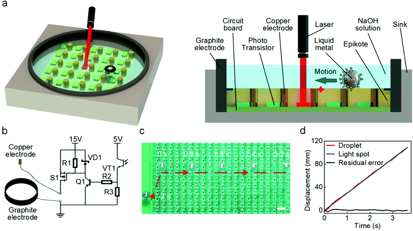
The droplet control system is composed of an experimental platform and control circuits, as shown in Fig. 1a and b. A circuit board was placed in a container made of acrylic and connected to the control circuits through a wire. The experimental platform has 441 copper electrodes arranged in 21 × 21 arrays (pitch of 5 mm), and each electrode is connected to the Drain terminal of the p-type metal–oxide–semiconductor field-effect transistor (p-MOSFET) in the control circuit. The control circuit for each electrode is shown in Fig. 1b. A light sensor made of a phototransistor in the control circuit was placed next to each copper electrode. A ring-shaped graphite electrode connected to the cathode (ground) was placed on the periphery of the circuit board. The circuit board was cast in transparent epoxy, with only tips of copper electrodes were exposed. All electrodes and LM droplets were immersed in a NaOH solution during experiments.If the light sensor is not exposed to the laser spot, the p-MOSFET is in a cut-off state and the copper electrode is inactivated. When the optical sensor is irradiated by an infrared laser (wavelength of 940 nm and power density of 1 mW cm−2), the p-MOSFET will be turned on, which will induce an electrical potential gradient pointing toward the activated copper electrode. The application of an external potential gradient in the NaOH solution will change the distribution of charges in the electric double layer (EDL) on the interface between the solution and the surface of LM.36,44 Such a change of charge distribution will affect the local tension at the interface (γ), as described by the Young–Lippman equation:45
 | (1) |
In our system, the copper electrode is connected to the anode. Upon activating the control circuit using light, an interfacial tension gradient will be induced along the surface of the LM droplet, thereby generating a Marangoni force to actuate the droplet towards the activated electrode.25,36,44,46,47 Since all copper electrodes are surrounded by the grounded ring-shaped graphite electrode (Fig. 1a), the induced potential gradient is always pointing toward the activated copper electrode and therefore, we expect that the LM droplet will move toward the light spot despite its original position. We verified this hypothesis by conducting an experiment with the light spot continually moving along a straight line, as shown in Fig. 1c (also see Movie S1, ESI†). A LM droplet was originally placed at the edge of the experimental platform (at −2 s), and it immediately actuated toward the light spot as soon as the laser was activated (at 0 s). The droplet stopped just below the light spot and then, it was able to track the spot to move along a straight line. In order to make the control process more clearly, we conducted an additional experiment utilizing a visible red laser beam to guide the movement of the LM droplet (see Movie S2, ESI†).
We set the speed of the light spot at 3 cm s−1 and the laser-guided LM droplet showed good tracking accuracy, as evidenced by the time-displacement curves for both laser and droplet given in Fig. 1d. The maximum potential gradient exists near the activated copper electrode, thereby inducing the largest Marangoni force on the LM droplet near the electrode before reaching the equilibrium position, which in turn generates a ‘trap’ to drag the droplet moving together with the light spot. Such a light induced actuation method avoids using complex pre-programmed control strategies, allowing for versatile activation of any selected electrodes.
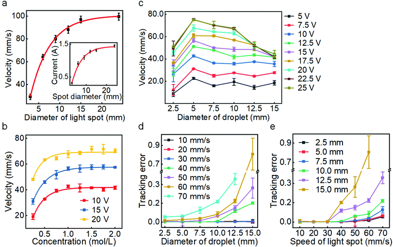
We next investigated the effect of different operating parameters on the guided actuating performance, including the size of the light spot, electrolyte concentration, voltage, and the size of LM droplet. By adjusting the diameter of the laser spot in the centre of the experimental platform and measuring the average velocity of the LM droplet placed 1 cm away from the centre of the spot, we found that increasing the spot's diameter can lead to a higher maximum actuating speed of the LM droplet, as summarized in Fig. 2a. This is because an increased laser spot size can activate more copper electrodes, producing a larger electrical current (see Fig. 2a inset) and generating a larger driving force. Based on this, we can control the maximum driving speed of the LM droplet by changing the light spot size.
We also explored the effect of NaOH concentration on the actuating performance. A LM droplet was released at a distance of 5 cm from the laser spot center, and we measured the average velocity of the LM droplets after moving 3 cm in NaOH solutions with different concentrations (Fig. 2b). For different levels of applied voltages, as the concentration increases, the average velocity of the LM droplet gradually rises due to the increased charges accumulated in the EDL. This would induce a larger gradient of interfacial tension along the LM surface upon the application of an external potential. When the solution concentration exceeds 1 mol L−1, the velocity become saturated due to the saturation of the initial EDL charge density on the LM surface.
We next examined the effect of droplet size on the actuating performance. For different voltage levels, the velocity of LM droplets rises and then drops as the droplet diameter increases, as shown in Fig. 2c. Increasing the droplet size can induce a greater voltage drop between the two ends of the LM droplet in the direction of the external potential gradient, thereby generating a greater gradient of interfacial tension for producing a larger Marangoni force. However, the velocity decreases when the droplet diameter exceeds 5 mm. This is likely because larger droplets have greater inertia (therefore smaller acceleration) and hydrodynamic drag. Meanwhile, a larger applied voltage can form a greater interfacial tension gradient for generating a larger actuating force to increase the velocity. However, excessive voltage (>20 V) causes intensified electrolysis of the solution.
Furthermore, we studied the effect of the size of the LM droplet on the light-tracking performance, which was characterized by the tracking error ε when the LM droplet tracked a moving laser spot along a straight line. If yi and fi are the instant displacement of the LM droplet and the light spot at the sampling point i, respectively, and ȳ is the mean of the displacement data obtained for all sampling points for the LM droplet, then the sum of total squares SStot, the sum of residual squares SSres, and the tracking error ε can be defined as:
 | (2) |
 | (3) |
 | (4) |
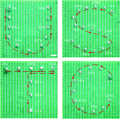
After understanding the light tracking performance of the LM droplet along a straight line, we further investigated the curved movement of the droplet on a 2D plane. A single LM droplet was guided by a laser spot to move along trajectories of characters of “U”, “S”, “T”, and “C”, as shown in Fig. 3 (also see Movie S3, ESI†). During this process, the LM droplet smoothly followed the path of the light spot with a near zero tracking error, indicating that the light control method is capable of guiding precise movement of a LM droplet along any complex trajectories in a 2D plane. Besides, the speed of the droplet was not compromised when moving along a curved path. A relatively high actuating speed of 55 mm s−1 was achieved when guiding a LM droplet along an s-shaped trajectory (letter “S” in Fig. 3).
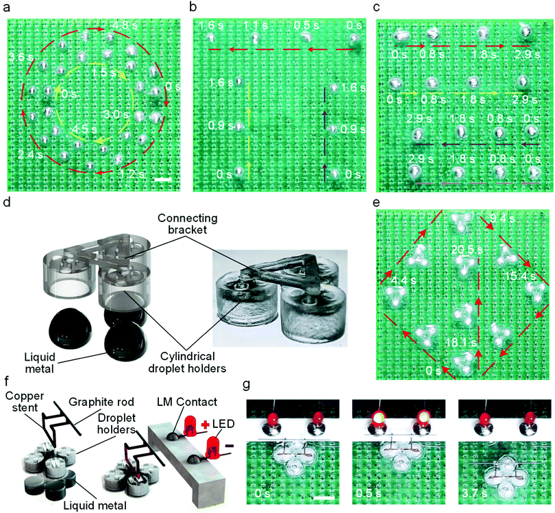
Leveraging the simplicity and versatility of the light guided actuation, we further explored the concurrent control of multiple LM droplets. Irradiating multiple laser beams simultaneously can activate electrodes in different regions, and this will generate multiple local potential gradients for trapping nearby LM droplets. We hypothesize that when multiple laser spots move at the same time, nearby LM droplets will follow these spots along different trajectories. We started examining our hypothesis using two laser spots for actuating two LM droplets, as shown in Fig. 4a (also see Movie S4, ESI†). The two LM droplets successfully tracked the trajectories of circles with different diameters, showing a promising multi-droplet motion control. Based on this, we next demonstrated the concurrent actuation of three and four droplets along different paths using more laser spots, as shown in Fig. 4b and c (also see Movie S4, ESI†), respectively. In fact, it is getting more difficult to control individual droplets as their number increases due to the interference between local droplet “traps”. We believe this issue can be resolved by increasing the distance between LM droplets, reducing the size of the droplets, and increasing the packing density of copper electrodes and photosensors.
Above experiments have demonstrated the control of one LM droplet using a light spot, it is natural to postulate that each light spot can also guide multiple droplets. To show this, we tested a vehicle carrier driven by LM wheels composed of three LM droplets. The vehicle body was 3D printed using transparent resin, which consists of three cylindrical droplet holders (diameter of 5 mm and height of 3.2 mm), as shown in Fig. 4d. LM droplets were injected into the holders using a syringe. Fig. 4e shows the control of the vehicle carrier using a laser spot along complex 2D trajectories (also see Movie S5, ESI†). The speed of the vehicle carrier is lower than that of a single droplet. This is probably due to the fact that droplet holders can compromise the generation of Marangoni forces. Harnessing the capability of the vehicle carrier, we designed a light-controlled relay to demonstrate the remote control of an electronic circuit. In doing so, a copper bracket fixed with a graphite rod was installed on a vehicle carrier driven by LM wheels composed of four LM droplets (Fig. 4f). Two light-emitting diodes (LED) were used to indicate the on–off of the circuit. Under the guidance of the laser beam, the vehicle approached the contact and connected the circuit (Fig. 4g). Similarly, we can also disconnect the circuit by guiding the vehicle away using the laser beam, thereby achieving the remote control of a circuit. Such a process is also shown in Movie S6, ESI.† These results show that light guided LM droplets has a great potential in advancing future droplet-based cobots systems.
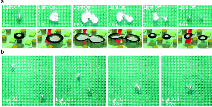
The shape of an LM droplet residing on a surface is the result of the combined effects of surface tension and gravity, therefore, it is possible to electrochemically change the surface tension of the LM droplet to induce deformation and even splitting. To achieve this, we used oblique-incident laser beams to irradiate the phototransistor underneath the LM droplet to activate the electrode. Fig. 5a shows the process of deformation and splitting of a single LM droplet (also see Movie S7, ESI†). Before activating the electrode, the oxide layer on the surface of the LM droplet was removed by the NaOH solution so that it can retain a spherical shape due to its large surface tension. As soon as the electrode underneath the LM droplet was activated, the LM droplet undergoes an electrochemical oxidation reaction to form an oxide layer on the surface.28–30 In this process, the rate of oxide formation is greater than its dissolution rate, and the oxide film on the surface gradually accumulates. The surface tension of the liquid metal drops sharply with the formation of the solid oxide layer and the droplet begins to flatten. Interestingly, a portion of the LM droplet tended to flow away from the part touching the electrode and eventually induced separation to form two droplets. After removing the laser, the oxide on the surface of the droplet was rapidly dissolved by the NaOH solution to restore the surface tension, and the two droplets became spherical. We believe such a separation process depends on the oxidative voltage and the size of the LM droplet. As such, we investigated the interplay of these two parameters for inducing droplet splitting, as shown in Fig. S1, ESI.†
In addition to splitting, we demonstrated the capability of the platform for controlled fusing of two LM droplets, as shown in Fig. 5b (also see Movie S7, ESI†). We used two laser beams to guide two LM droplets to approach and collide with each other. At a relatively high speed, the two droplets can overcome the surface tension barrier by inertia and finally merged into a large LM droplet.
Limitation of the technique
The method produces hydrogen and oxygen bubbles during the actuating processes because of electrolysis. This may hinder the actuation of the droplet. The produced gas can escape into the air rather than accumulating in the platform, therefore, does not pose a security hazard. Besides, an AC voltage with a DC offset can be utilized to reduce the generation of bubbles. Moreover, the resolution of the LM droplet actuation is limited by the density of the electrode arrays. Improving the control precision by increasing the density of electrodes is an available solution.Conclusions
In conclusion, we have reported on a versatile and powerful light-controlled manipulation of LM droplets. We demonstrated that such a method can readily guide multiple LM droplets for inducing concurrent actuation, splitting, and merging. We showed the actuation of single and multiple LM droplets along any arbitrary trajectory in a 2D plane. According to our observations, LM droplets can follow trajectories of infrared laser spots with good accuracy at desired speeds. The actuation may be affected by the size of the LM droplet, electrolyte concentration, voltage, as well as diameter, and the moving speed of the laser spot. Controlled electrochemical oxidation and splitting of a LM droplet was also achieved by an oblique-incident laser beam. We envisage such a light induced control method for manipulating LM droplets provides new directions and technical approaches for pioneering future research in fields of MEMS, field-programmable robotics, and droplet-based liquid cobots.Experimental section
Materials
EGaIn alloy (75% Ga, 25% In) was purchased from Santech Materials Co., Ltd, USA. NaOH was purchased from Aladdin, China. Transparent epoxy adhesive was purchased from Dongguan Jinkun Composite Materials CO., Ltd, China. Lasers (wavelength of 940 nm and Maximum power of 10 mW) were purchased from Zhongshan Shuanghong Electronics Co., Ltd, China. Phototransistors (activating wavelength of 940 nm) were purchased from EGing Photovoltaic Technology Co., Ltd, China.Control of LM droplets
The laser moved along trajectories of characters of “U”, “S”, “T”, and “C” in the track made of acrylic. A servo motor was used to control two laser beams to drive two LM droplets to track the trajectories of circles with different diameters. The movement of the lasers along a straight path was controlled by a linear translational stage.Vehicle carrier
The vehicle body was 3D printed using transparent resin, which consists of three cylindrical droplet holders (diameter of 5 mm and height of 3.2 mm). Cylindrical droplet holders have four holes on the upper surface to facilitate the injection of LM droplets and allow the solution to enter the cavity.Videos and photos
Videos were captured using a DSLR camera (5D MARK2, Canon, Japan), and the snapshots were extracted from these videos. The velocity data was obtained using a high-speed camera (HERO 5, GoPro, USA).Author contributions
H. R. and H. J. contributed equally to this work. H. R., S.-Y. T., and S. Z. designed research; H. R., H. J., J. S., J. X., E. W., and D.-A. G. conducted experiments; H. R., H. J., J. S., J. X., E. W., D.-A. G., S.-Y. T., X. L., W. L., and S. Z. analysed data; H. R., S.-Y. T., and S. Z. wrote the paper; S.-Y. T., X. L., W. L., and S. Z. supervised the project.Conflicts of interest
There are no conflicts to declare.Acknowledgements
This research has been partially supported by the following funding: National Natural Science Foundation of China grant 51828503 (S. Z.), National Natural Science Foundation of China grant U1713206 (S. Z.), National Natural Science Foundation of China grant 61503270 (S. Z.), and Fundamental Research Funds for the Central Universities WK5290000001 (H. R.).References
- Z. J. Yang, J. J. Wei, Y. I. Sobolev and B. A. Grzybowski, Nature, 2019, 567, E11 CrossRef CAS.
- Y. Xiao, S. Zarghami, K. Wagner, P. Wagner, K. C. Gordon, L. Florea, D. Diamond and D. L. Officer, Adv. Mater., 2018, 30, 1870259 CrossRef.
- S. An, M. Y. Zhu, K. Gu, M. D. Jiang, Q. C. Shen, B. W. Fu, C. Y. Song, P. Tao, T. Deng and W. Shang, Nanoscale, 2020, 12, 4295–4301 RSC.
- A. Li, H. Z. Li, Z. Li, Z. P. Zhao, K. X. Li, M. Z. Li and Y. L. Song, Sci. Adv., 2020, 6, eaay5808 CrossRef CAS.
- X. J. Fan, X. G. Dong, A. C. Karacakol, H. Xie and M. Sitti, Proc. Natl. Acad. Sci. U. S. A., 2020, 117, 27916–27926 CrossRef CAS.
- L. Nian, Z. H. Chen, S. Herbst, Q. Y. Li, C. Z. Yu, X. F. Jiang, H. L. Dong, F. H. Li, L. L. Liu, F. Wurthner, J. W. Chen, Z. Q. Xie and Y. G. Ma, Adv. Mater., 2016, 28, 7521–7526 CrossRef CAS PubMed.
- A. J. Wang, E. P. Dillon, S. Maharjan, K. S. Liao, B. P. McElhenny, T. Tong, S. Chen, J. M. Bao and S. A. Curran, Adv. Mater. Interfaces, 2021, 8, 2001720 CrossRef CAS.
- Z. D. Li, S. L. Zhang, R. C. Xu, Q. W. Zhang, Z. H. Wang and C. L. Fu, Appl. Organomet. Chem., 2019, 33, e5105 Search PubMed.
- C. Lefebvre, L. Fortier and N. Hoffmann, Eur. J. Org. Chem., 2020, 1393–1404 CrossRef CAS.
- S. A. Chechetka, Y. Yu, X. Zhen, M. Pramanik, K. Y. Pu and E. Miyako, Nat. Commun., 2017, 8, 1–19 CrossRef.
- C. H. Goss, Y. Kaneko, L. Khuu, G. D. Anderson, S. Ravishankar, M. L. Aitken, N. Lechtzin, G. Zhou, D. M. Czyz, K. McLean, O. Olakanmi, H. A. Shuman, M. Teresi, E. Wilhelm, E. Caldwell, S. J. Salipante, D. B. Hornick, R. J. Siehnel, L. Becker, B. E. Britigan and P. K. Singh, Sci. Transl. Med., 2018, 10, eaat7520 CrossRef.
- Q. Wang, Y. Yu, K. Q. Pan and J. Liu, IEEE Trans. Biomed. Eng., 2014, 61, 2161–2166 Search PubMed.
- M. D. Dickey, Adv. Mater., 2017, 29, 1606425 CrossRef.
- H. Chang, R. Guo, Z. Q. Sun, H. Z. Wang, Y. Hou, Q. Wang, W. Rao and J. Liu, Adv. Mater. Interfaces, 2018, 5, 1800571 CrossRef.
- M. M. Y. A. Alsaif, N. Pillai, S. Kuriakose, S. Walia, A. Jannat, K. Xu, T. Alkathiri, M. Mohiuddin, T. Daeneke, K. Kalantar-Zadeh, J. Z. Ou and A. Zavabeti, ACS Appl. Nano Mater., 2019, 2, 4665–4672 CrossRef CAS.
- L. T. Yi, J. J. Li, C. R. Guo, L. Li and J. Liu, J. Med. Devices, 2015, 9, 044507 CrossRef.
- F. M. Allioux, S. Merhebi, M. B. Ghasemian, J. B. Tang, A. Merenda, R. Abbasi, M. Mayyas, T. Daeneke, A. P. O'Mullane, R. Daiyan, R. Amal and K. Kalantar-Zadeh, Nano Lett., 2020, 20, 4403–4409 CrossRef CAS PubMed.
- K. Zuraiqi, A. Zavabeti, F. M. Allioux, J. B. Tang, C. K. Nguyen, P. Tafazolymotie, M. Mayyas, A. V. Ramarao, M. Spencer, K. Shah, C. F. McConville, K. Kalantar-Zadeh, K. Chiang and T. Daeneke, Joule, 2020, 4, 2290–2321 CrossRef CAS.
- F. Hoshyargar, H. Khan, K. Kalantar-Zadeh and A. P. O'Mullane, Chem. Commun., 2015, 51, 14026–14029 RSC.
- J. DeMuth, E. Fahrenkrug and S. Maldonado, Cryst. Growth Des., 2016, 16, 7130–7138 CrossRef CAS.
- E. Fahrenkrug and S. Madonado, Acc. Chem. Res., 2015, 48, 1881–1890 CrossRef CAS PubMed.
- J. DeMuth, L. Y. Ma, M. Lancaster, S. Acharya, Q. Cheek and S. Maldonado, Cryst. Growth Des., 2018, 18, 677–685 CrossRef CAS.
- K. Khoshmanesh, S. Y. Tang, J. Y. Zhu, S. Schaefer, A. Mitchell, K. Kalantar-Zadeh and M. D. Dickey, Lab Chip, 2017, 17, 974–993 RSC.
- J. Jeon, J. B. Lee, S. K. Chung and D. Kim, Lab Chip, 2017, 17, 128–133 RSC.
- S. Y. Tang, V. Sivan, K. Khoshmanesh, A. P. O'Mullane, X. K. Tang, B. Gol, N. Eshtiaghi, F. Lieder, P. Petersen, A. Mitchell and K. Kalantar-Zadeh, Nanoscale, 2013, 5, 5949–5957 RSC.
- S. Y. Tang, Y. L. Lin, I. D. Joshipura, K. Khoshmanesh and M. D. Dickey, Lab Chip, 2015, 15, 3905–3911 RSC.
- M. R. Khan, C. B. Eaker, E. F. Bowden and M. D. Dickey, Proc. Natl. Acad. Sci. U. S. A., 2014, 111, 14047–14051 CrossRef CAS PubMed.
- J. Zhang, L. Sheng and J. Liu, Sci. Rep., 2014, 4, 1–8 Search PubMed.
- L. Sheng, J. Zhang and J. Liu, Adv. Mater., 2014, 26, 6036–6042 CrossRef CAS PubMed.
- J. Wissman, M. D. Dickey and C. Majidi, Adv. Sci., 2017, 4, 1700169 CrossRef.
- X. P. Li, S. Li, Y. M. Lu, M. Z. Liu, F. X. Li, H. Yang, S. Y. Tang, S. W. Zhang, W. H. Li and L. N. Sun, ACS Appl. Mater. Interfaces, 2020, 12, 37670–37679 CrossRef CAS.
- E. J. Markvicka, M. D. Bartlett, X. N. Huang and C. Majidi, Nat. Mater., 2018, 17, 618–624 CrossRef CAS PubMed.
- Y. Lu, Q. Y. Hu, Y. L. Lin, D. B. Pacardo, C. Wang, W. J. Sun, F. S. Ligler, M. D. Dickey and Z. Gu, Nat. Commun., 2015, 6, 1–10 CAS.
- F. X. Li, J. Shu, L. R. Zhang, N. L. Yang, J. Xie, X. P. Li, L. Cheng, S. L. Kuang, S. Y. Tang, S. W. Zhang, W. H. Li, L. N. Sun and D. Sun, Appl. Mater. Today, 2020, 19, 101911 Search PubMed.
- H. Liu, M. X. Li, Y. H. Li, H. Yang, A. Li, T. J. Lu, F. Li and F. Xu, Soft Matter, 2018, 14, 3236–3245 RSC.
- S. Y. Tang, K. Khoshmanesh, V. Sivan, P. Petersen, A. P. O'Mullane, D. Abbott, A. Mitchell and K. Kalantar-zadeh, Proc. Natl. Acad. Sci. U. S. A., 2014, 111, 3304–3309 CrossRef CAS PubMed.
- G. Y. Mao, M. Drack, M. Karami-Mosammam, D. Wirthl, T. Stockinger, R. Schwodiauer and M. Kaltenbrunner, Sci. Adv., 2020, 6, eabc0251 CrossRef CAS.
- X. X. Li, J. Xie, S. Y. Tang, R. Xu, X. P. Li, W. H. Li and S. W. Zhang, IEEE Trans. Ind. Inform., 2019, 15, 2535–2543 Search PubMed.
- Y. Y. Yao and J. Liu, RSC Adv., 2016, 6, 56482–56488 RSC.
- C. B. Eaker and M. D. Dickey, Appl. Phys. Rev., 2016, 3, 031103 Search PubMed.
- A. Zavabeti, T. Daeneke, A. F. Chrimes, A. P. O'Mullane, J. Z. Ou, A. Mitchell, K. Khoshmanesh and K. Kalantar-zadeh, Nat. Commun., 2016, 7, 1–10 Search PubMed.
- J. Zhang, Y. Y. Yao, L. Sheng and J. Liu, Adv. Mater., 2015, 27, 2648–2655 CrossRef CAS.
- X. K. Tang, S. Y. Tang, V. Sivan, W. Zhang, A. Mitchell, K. Kalantar-zadeh and K. Khoshmanesh, Appl. Phys. Lett., 2013, 103, 174104 CrossRef.
- J. Lee and C. J. Kim, J. Microelectromech. Syst., 2000, 9, 171–180 CAS.
- D. C. Grahame, Chem. Rev., 1947, 41, 441–501 CrossRef CAS PubMed.
- T. Y. Liu, P. Sen and C. J. C. J. Kim, J. Microelectromech. Syst., 2012, 21, 443–450 CAS.
- X. Zhao, S. Xu and J. Liu, Front. Energy, 2017, 11, 535–567 CrossRef.
Footnote |
| † Electronic supplementary information (ESI) available: Supporting information and Movies S1–S7. See DOI: 10.1039/d1mh00647a |
| This journal is © The Royal Society of Chemistry 2021 |

