Functional separators towards the suppression of lithium dendrites for rechargeable high-energy batteries
Zhendong
Hao
,
Qing
Zhao
,
Jiadong
Tang
,
Qianqian
Zhang
 *,
Jingbing
Liu
,
Yuhong
Jin
and
Hao
Wang
 *
*
Key Laboratory for New Functional Materials of Ministry of Education, Faculty of Materials and Manufacturing, Beijing University of Technology, Beijing 100124, P. R. China. E-mail: zhangqianqian@bjut.edu.cn; haowang@bjut.edu.cn
First published on 28th September 2020
Abstract
Lithium metal battery (LMB) is considered to be one of the most promising electrochemical energy storage devices due to the high theoretical specific capacity and the lowest redox potential of metallic lithium; however, some key issues caused by lithium dendrites on the lithium metal anode seriously hinder its real-world applications. As an indispensable part of LMBs, the separator could serve as a physical barrier to prevent direct contact of the two electrodes and control ionic transport in batteries; it is an ideal platform for the suppression of lithium dendrites. In this review, the mechanism of lithium dendrite nucleation and growth are firstly discussed and then some advanced techniques are introduced for the precise characterization of lithium dendrites. On the basis of dendritic nucleation and growth principle, several feasible strategies are summarized for suppressing lithium dendrites by utilizing functional separators, including providing a mechanical barrier, promoting homogeneous lithium deposition, and regulating ionic transport. Finally, some challenges and prospects are proposed to clear the future development of functional separators. We anticipate that this paper will provide a new insight into the design and construction of functional separators for addressing the issues of lithium dendrites in high-energy batteries.
1. Introduction
Sustaining the pursuit of clean and renewable energy has always been an important theme for human development. Lithium ion battery (LIB) is one of the key research objects among various electrochemical power sources since its commercialization in 1990s and has been widely applied in industry and daily life.1–5 However, the energy density of electrode materials of the state-of-the-art LIBs (especially graphite) nearly reach their physical limit, and is not enough to meet the increasing demand of some advanced energy storage devices.6,7 Lithium metal battery (LMB) is regarded as one of the most promising rechargeable high-energy batteries due to the high theoretical specific capacity (3860 mA h g−1, which is ten times larger than that of graphite) and the lowest redox potential (−3.04 V vs. standard hydrogen electrode) of metallic lithium.8–10 Some LMBs such as lithium–organic batteries (LOBs), lithium–sulfur batteries (LSBs), and lithium–air batteries (LABs) have been extensively studied for the construction of high energy density batteries in the past few decades.11–16It is well-accepted that addressing the lithium dendrite issue is a key for promoting the practical application of LMBs. Specifically, during the repeated plating and stripping processes of lithium metal, the deposition of lithium ions (Li+) will form a heterogeneous and unstable layer, leading to the formation of lithium dendrites with unpredictable shape, thus causing the degradation of battery performance or even some safety issues.17–19 In recent years, great efforts have been devoted to solving the lithium dendrite issue, such as anode structure optimization,20,21 interface modification,22,23 separator modification,24,25 electrolyte additives,26,27 construction of artificial solid electrolyte interphase (SEI),28,29 and current collector modification.30,31 Among these, the separator functionalization strategy possesses some advantages that distinguishes it from the others. Firstly, the separator mainly acts as a physical barrier to prevent the direct contact of the two electrodes, which is able to prevent the passing of lithium dendrites between the two electrodes, which causes short-circuit of the battery.32–34 Then, as essential transmission paths for Li+ and electrolyte anions, the ionic transport properties in the batteries could be regulated by modifying the composition and structure of the separators, which is highly related with the nucleation and growth of lithium dendrites.35–37 Moreover, separator functionalization usually has little influence on the energy density of LMBs because of no obvious change in the volume or the mass of the batteries.33,38,39 Thus, separator functionalization provides a good alternative for the suppression of lithium dendrites in LMBs. Despite many insightful and impactful reviews concerning strategies for suppressing lithium dendrites, most of them are based on the electrode design and electrolyte modification, to the best of our knowledge. Thus, a comprehensive discussion and summary aimed at separator functionalization for boosting lithium metal anode may contribute new insights into the construction of rechargeable high-energy batteries.
In this paper, recent advances and progresses of functional separators for suppressing lithium dendrites in LMBs are reviewed in detail for the first time. Firstly, lithium dendritic nucleation and growth mechanism, as well as some advanced characterization techniques for observing lithium dendrites, are briefly introduced. Then, we have discussed the roles of separator functionalization for suppressing lithium dendritic nucleation and growth in LMBs. Next, the typical strategies of separator functionalization are summarized in detail, including providing a mechanical barrier, promoting homogeneous lithium deposition, and regulating ionic transport. Finally, several perspectives on the future development of functional separators for constructing advanced LMBs are proposed.
2. Mechanism of lithium dendritic nucleation and growth
2.1. Dendritic nucleation
Metallic dendrite nucleation mechanism was firstly proposed by Sand in 1901, which has been widely accepted in the case of lithium dendrites and often used to obtain the nucleation time of lithium dendrites.40 In LMBs with a binary electrolyte at high charge rates, the concentration of cations at the surface of the electrode will decrease to zero at Sand's time. After this, the deposition behavior of the cations tends to happen on the surface of the lithium metal, leading to the formation of lithium dendrites. The nucleation time of lithium dendrites could be determined by the Sand's formula as follows.40,41where Dapp is the apparent diffusion coefficient, zc is the cationic charge number, c0 is the bulk salt concentration, F is the Faraday's constant, J is the current density, and tLi+ and ta = 1 − tLi+ are the transference number of Li+ and associated anions.
It could be concluded that lithium dendrites will form at Sand's time when the current density becomes over-limiting. Thus, the prolongation of the nucleation time of lithium dendrites could be an effective way to suppress the formation of lithium dendrites. Based on Sand's formula, lowering the current density and increasing the tLi+ are two feasible strategies. The improvement of tLi+ could be achieved by separator modification, electrolyte modification, etc.
2.2. Dendritic growth
Persistent lithium plating on the metal surface leads to the growth of lithium dendrites from the nucleation sites under certain conditions.42 It is well-known that an SEI film forms on the surface of lithium metal through a reaction with the electrolyte and lithium deposition occurs below the SEI film. Inhomogeneous lithium plating causes local volume expansion and thus breaks the fragile SEI film. Then, a further plating leads to uncontrollable dendrite growth from the cracks, which may cause internal short-circuit of the battery or even serious security issues. During lithium stripping, the dissolution of the dendrite roots connected with the lithium metal will produce massive “dead Li”, which could block the ionic transport. Thus, apart from the safety hazards, lithium dendrite growth and “dead Li” formation also cause poor battery performance including capacity fading and coulombic efficiency loss.Seeking ways to inhibit dendrite growth, several research models have been proposed in the recent years to elucidate the growth mechanism of lithium dendrites, such as the deposition and dissolution model, SEI model, charge-induced model, phase-field model, and film growth model.43–49 Among these, the charge-induced model gives a comprehensive explanation that the protuberance of nucleation sites has a much higher electrical field compared with other parts of the lithium metal surface, which will attract more Li+ and thus promote the growth of lithium dendrites at the tip (Fig. 1a).47 The protuberance with a high curvature provides a larger surface area for inhomogeneous lithium deposition and further facilitates dendritic growth. Particularly for high-current electroplating, the growth process of lithium dendrites could be significantly promoted because a faster Li+ migration further causes inhomogeneous Li deposition. From the above mechanism, achieving homogeneous Li+ deposition on lithium metal is of great significance to avoid the growth of dendrites from the nucleation sites (Fig. 1b), which creates possibilities for enabling LMB operation at a high working current density.
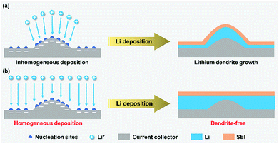 | ||
| Fig. 1 Dendrite growth on lithium metal anodes with nucleation sites in response to inhomogeneous (a) and homogeneous (b) Li+ deposition. | ||
3. Characterization techniques for lithium dendrites
Lithium dendrite characterization could be classified as the ex situ and in situ techniques. The former refers to the direct morphology observation and textural analysis of the dendrites on the lithium metal electrode obtained from the used battery, and the latter refers to achieving real-time monitoring of dendritic formation and growth during repeated lithium plating/stripping in a working battery.3.1. Ex situ characterization techniques
Scanning electron microscopy (SEM) and transmission electron microscopy (TEM) provide the most intuitive ways for observing lithium dendrites on the lithium metal electrode. The observed morphologies of lithium dendrites are mainly needle-like, moss-like, and tree-like.50,51 Although electron microscopy (EM) observation is the most common approach, the ultrahigh activity of lithium metal in air makes rigorous demands on the battery disassembly and metal electrode transfer. To address the above challenges, Cui's group utilized cryo-EM to preserve the image of sensitive lithium and achieved an atomic-level observation of the lithium dendrites (Fig. 2a).52 The microstructure of the lithium dendrites could be well preserved during the cryo-transfer. In contrast, lithium dendrites would be corroded quickly after short air exposure during the transfer of the sample into the standard TEM at room temperature (Fig. 2b). The air-exposed lithium dendrites possessed a much rougher surface and darker contrast than the cryo-transferred one due to the formation of polycrystalline artifacts (inset of Fig. 2b). Furthermore, the lithium dendrites were seriously damaged by the focused electron beam of standard TEM at a high resolution with an electron dose rate of ∼500 e Å−2 s−1 even for 1 s (Fig. 2c), which could be avoided by utilizing the cryo-EM technique.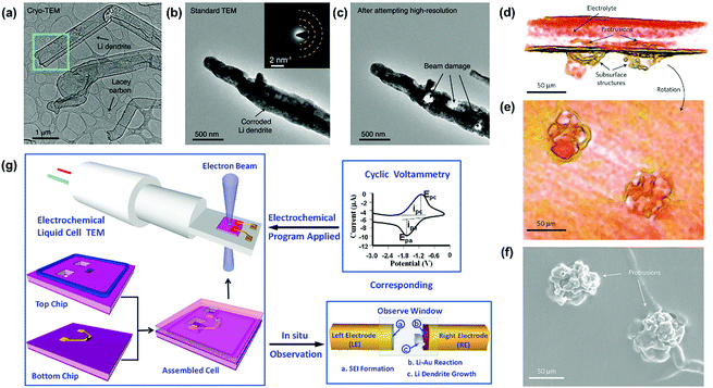 | ||
| Fig. 2 Several advanced techniques for the observation of lithium dendrites. (a) Cryo-EM image of Li metal dendrites. Electron dose rate < 1 e Å−2 s−1. (b) Standard TEM image of Li metal dendrite with ∼1 s air exposure at room temperature. Inset is the selected-area electron diffraction pattern. (c) Standard TEM image of the dendrite from (b) after exposure to an electron dose rate of ∼500 e Å−2 s−1 for ∼1 s. The three holes were formed immediately after this exposure. Reproduced with permission from ref. 52. Copyright 2017, AAAS. (d) 3D reconstructed volume of a cell with C = 84 C cm−2, containing two, closely spaced dendrites. (e) The reconstructed volume was rotated such that the viewer is within the electrolyte looking at the dendrites. (f) SEM micrograph of the bottom electrode of the same cell, after dissolving away the electrolyte, showing the dendritic structures. The SEM images contain no direct evidence for the presence of subsurface structures under the dendritic protrusions. Reproduced with permission from ref. 53. Copyright 2013, Nature. (g) A scheme of in situ TEM observation of the electrochemical reaction using an electrochemical liquid cell. Reproduced with permission from ref. 56. Copyright 2014, American Chemical Society. | ||
Furthermore, some advanced characterization techniques have also been employed to achieve more accessible information of lithium dendrites in the recent years. For instance, Harry and co-workers reconstructed the 3D volume of a portion of a cell that contained two dendritic structures near each other obtained during the intermediate stage of cycling (Fig. 2d–f).53 By utilizing synchrotron hard X-ray microtomography, the dendritic structures lying beneath the electrode/electrolyte interface could be obtained, which could not be observed by the standard SEM image (Fig. 2f). Apart from morphology observation, textural analysis is also used for characterizing the growth progress of lithium dendrites. X-ray diffraction (XRD) is widely applied to characterize the changes in the crystal structure of lithium metal after the electrochemical reaction.54 The typical characteristic peaks of the (110) and (200) lattice planes demonstrate an intensity variation after several cycles, reflecting the growth situation of the lithium dendrites. As discussed above, these ex situ imaging techniques are more suitable for observing the long dendrites formed on the surface of the lithium metal or dispersed in the electrolyte. There is still a limitation when characterizing a tiny crystal nucleus or observing the growth process of lithium dendrites.
3.2. In situ characterization techniques
In recent years, various in situ characterization techniques have been developed to study the formation and growth process of lithium dendrites under the application of an electric field, which provide good platforms for studying the underlying growth mechanism of dendrites on the lithium anode assembled in the LMBs.In situ imaging techniques mainly include in situ optical microscopy, SEM, and TEM. Tailored electrochemical cells are necessary for conducting in situ observations of the lithium dendrites. An in situ optical microscope has the superiority of simple operation but the observations are limited by the spatial resolution. In contrast, the in situ SEM and TEM techniques could achieve a much higher resolution up to a few nanometers. For instance, Rong et al. applied in situ SEM to investigate the lithium plating and stripping processes in the liquid electrolyte.55 By utilizing in situ SEM, some critical steps such as lithium dendrite growth, dissolution, and “dead Li” formation could be distinctly observed in real time. Furthermore, Zeng and co-workers carried out the in situ TEM observation of the dendritic growth of lithium metal in the commercial LiPF6/EC/DEC electrolyte (Fig. 2g)56 Firstly, the liquid electrolyte was loaded into the biasing cell through the reservoirs and flowed into the cell by capillary force. Then, two pieces of Cu foil were used to cover the two reservoirs and the liquid cell was sealed using epoxy. The sealed cell was put into the homemade TEM holder and the gold wires conjoined on the electrode pads of the biasing cell were connected to the electric pads at the tip of the electrochemical holder. The detailed electrochemical reactions could be in situ monitored under the applied cyclic voltammetry. In the study, the dynamic process that occurred on the electrodes could be observed including the SEI formation and lithium dendrite growth.
Except for in situ EM techniques, in situ X-ray imaging techniques, such as transmission X-ray microscopy (TXM) and scanning transmission X-ray microscopy (STXM), have also been applied for lithium dendrite observation.57,58 X-ray has a similar wavelength to the electron beam but causes less damage to the samples.59 Recently, Yu and co-workers detected the evolution of lithium plating and stripping processes in the battery under operando conditions using synchrotron-based X-ray imaging methods.60 The morphological evolution during lithium plating in a large field of view was studied in detail by regulating the battery operating conditions including current density, electrolyte type, concentration, and additives. The results demonstrated that these variables remarkably influenced the lithium plating mechanism and led to the formation of cactus-Li/volcanic-Li. Besides, magnetic resonance imaging (MRI) technique is another powerful tool for the in situ investigation of the nucleation and growth processes of lithium, which could explore the magnetic nuclear structural properties in the interior of the material without considering the surface barrier.59,61 An in situ MRI study in symmetric lithium metal cells based on the 7Li metal and its electrolyte revealed the direct correlation between lithium dendrite growth and the changes in the electrolyte concentration gradient.61 Therefore, the in situ characterization could provide more information on the lithium dendrites compared with the ex situ ones but these techniques are usually highly dependent on the designs of in situ electrochemical cells.
4. Roles of functional separators for suppressing lithium dendrites
Conventional polyolefin separators, typically commercialized polyethylene (PE) and polypropylene (PP), could meet the basic performance requirements of LMB:33,62 (1) The polyolefin separator has an intrinsic insulating property, which could prevent electrical contact between the cathode and the anode in the battery. (2) The polyolefin separator is a flexible and microporous membrane with suitable porosity and low thickness (tens of microns), which provides accessible passages for the passage of Li+. (3) Electrolyte wettability enables the separator uptake electrolyte for the long-term operation of the battery. (4) The polyolefin separator has a chemical inertness such that it does not participate in the electrochemical reactions of the battery. However, routine separators can hardly address some special issues existing in LMBs. In this view, some additional functions are endowed to the separators to boost the batteries. For instance, functional separators with permselective behaviors could effectively inhibit polysulfide shuttling in the LSBs.63–67 For settling the problems of lithium dendrites in LMBs, separator functionalization also provides feasible solutions, as in the following discussions.As a physical barrier between the cathode and the anode, the functional separator with a much higher mechanical strength could prevent lithium dendrite piercing and thus avoid undesired short-circuiting or even serious security issues (Fig. 3). Such high mechanical strengths are usually achieved by utilizing functional ceramics (Al2O3, SiO2, and LiLaZrTaO) and polymer materials (poly(ether ether ketone) (PEEK), polyvinyl alcohol (PVA)) with an elastic modulus higher than that of lithium dendrites (6.2 GPa). The functional separators usually have two typical structures. One is the double-layer membrane with ceramic nanoparticles coated onto routine polyolefin separators and the other is the self-standing porous ceramic or polymer membrane. Although mechanical barrier roles of the functional separators could alleviate internal short-circuit and the safety issues of LMBs, the formation of lithium dendrites is still not controlled; thus, the battery performance will degrade rapidly.
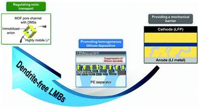 | ||
| Fig. 3 Roles of functional separators for suppressing lithium dendrites. Typical examples: Reproduced with permission from ref. 68. Copyright 2019, Wiley. Reproduced with permission from ref. 69. Copyright 2015, American Chemical Society. Reproduced with permission from ref. 70. Copyright 2016, American Chemical Society. | ||
In order to suppress the lithium dendrites, some strategies of separator functionalization are proposed based on the mechanism of dendritic formation and growth. As discussed above, the growth of lithium dendrites stems from inhomogeneous Li+ deposition on the lithium metal anode. In this view, the separator could provide a good platform for achieving homogeneous Li+ flux on the surface of the lithium metal. For example, constructing ordered pore structures on the separator will ensure a uniform distribution of Li+ flux on the lithium metal. Typical examples of such functional separators include microporous fiber membrane, nanoporous anodic aluminum oxide (AAO) membranes, 2D graphene oxide (GO) layer, and routine separators functionalized by metal–organic frameworks (MOFs) with sub-nanoscaled pores. Besides, improving the affinity between the separator and the lithium metal anode can also promote Li+ deposition in a more uniform manner. Some materials with good lithium affinity such as polydopamine and chitin have been applied to develop functional separators. Homogeneous Li+ deposition promoted by functional separators could effectively suppress the lithium dendrites but the dendritic growth process could not be stopped. From the dendritic nucleation principle, prolonging the Sand's time (nucleation time) will slow down the nucleation process of the lithium dendrites, thus fundamentally preventing dendritic growth. As mentioned above, Sand's time presents a negative correlation with ta. Thus, controlling anion transport near the lithium metal anode will inhibit dendritic nucleation. During battery operation, Li+ and anions are transported between the two electrodes through separators because the liquid electrolyte is absorbed into the separators. In this view, anion transfer could be controlled by the functionalization of the separator, just like solid-state electrolyte with tethered anions and mobile Li+. Cation-selective separators could be constructed by utilizing the size sieve of nanoporous materials (MOFs and GO) or electrostatic interactions based on negatively charged moieties such as Nafion and poly(acrylic acid) (PAA). Moreover, the Li+ selectivity will be improved significantly by introducing negative charges on the surface of nanochannel membranes due to the strong electrostatic binding in nano-confined spaces. The strategy based on functional separators regulating ionic transport is anticipated to prevent the nucleation and growth of lithium dendrites for constructing dendrite-free LMBs (Fig. 3).
5. Remedies on lithium dendrites by functional separators
5.1. Providing a mechanical barrier
For conventional separators with low elastic modulus, uncontrollable lithium dendrite growth will penetrate the separator and thus lead to an internal short-circuit of the battery.71–73 Thus, enhancing the mechanical strength of the separator is a feasible approach to provide effective physical barrier against lithium dendrites. In this case, some functional materials with superior mechanical strength, such as ceramics and polymer, have been used to modify routine separators or to construct novel functional separators.Ceramic materials are widely used to construct robust functional separators mainly because of their high mechanical strength and corrosion resistance. Al2O3 is a kind of typical ceramic material that has been used as an additive to improve the mechanical strength of conventional separators in recent years.74–76 For instance, Na and co-workers introduced a robust Al2O3 coating on the commercial PP separator by utilizing a polymeric binder of poly(phenyl-co-methacryloxypropyl)silsesquioxane (LPMA64) to resist lithium dendrites (Fig. 4a).70 For a comparison, the mechanical capacities of several separators were studied via the nanoindentation-derived elastic moduli measurements. As shown in Fig. 4b, the elastic modulus of commercial PP separator was determined to be 2.1 GPa. The PE–PP–PE trilayer separator and ultrahigh molecular weight PE (UHMW PE) coated with polytetrafluoroethylene (PTFE)/Al2O3 layer had the elastic modulus of 1.5 and 3.8 GPa, respectively. All these separators were insufficient to meet the elastic modulus of the lithium metal electrode (4.0 GPa) and the minimum modulus to suppress lithium dendrite growth (6.2 GPa). In contrast, the synthesized separator sample of A2L1 (Al2O3![[thin space (1/6-em)]](https://www.rsc.org/images/entities/char_2009.gif) :
:![[thin space (1/6-em)]](https://www.rsc.org/images/entities/char_2009.gif) LPMA64 weight ratio of 2
LPMA64 weight ratio of 2![[thin space (1/6-em)]](https://www.rsc.org/images/entities/char_2009.gif) :
:![[thin space (1/6-em)]](https://www.rsc.org/images/entities/char_2009.gif) 1) delivered a high elastic modulus up to 7.3 GPa, which could be employed to suppress lithium dendrites in LMBs. Similarly, Hwang and co-workers functionalized the pristine PP separator with dual side coating of Al2O3 and graphene in LSBs (Fig. 4c).77 Among these, the Al2O3 coating was used to enhance mechanical property of the separator to prevent lithium dendrite piercing and the graphene coating acted as a highly conductive layer to improve charge transfer for achieving highly efficient sulfur utilization. The battery equipped with this dual functional separator demonstrated superior performance such as a high discharge capacity of 1375 mA h g−1 at 0.1 C, superior rate capability up to 5 C, and excellent cycling stability at 1 C, given the high sulfur loading of about 4.0 mg cm−2 compared with conventional separators. Very recently, Liang et al. developed a nano-shield functional separator for inhibiting lithium dendrites by the spin-coating of SiO2 nanoparticles onto commercial polyolefin separators.78 The curve surface effect could reduce the stress intensity of the separator and increase the growth pathway of the lithium dendrites, contributing to a large suppression of lithium dendrites. As a result, LMB equipped with the nano-shield separator presented a cycle life of more than 110 h, which further sheds light on the role of separator functionalization towards high-performance LMBs.
1) delivered a high elastic modulus up to 7.3 GPa, which could be employed to suppress lithium dendrites in LMBs. Similarly, Hwang and co-workers functionalized the pristine PP separator with dual side coating of Al2O3 and graphene in LSBs (Fig. 4c).77 Among these, the Al2O3 coating was used to enhance mechanical property of the separator to prevent lithium dendrite piercing and the graphene coating acted as a highly conductive layer to improve charge transfer for achieving highly efficient sulfur utilization. The battery equipped with this dual functional separator demonstrated superior performance such as a high discharge capacity of 1375 mA h g−1 at 0.1 C, superior rate capability up to 5 C, and excellent cycling stability at 1 C, given the high sulfur loading of about 4.0 mg cm−2 compared with conventional separators. Very recently, Liang et al. developed a nano-shield functional separator for inhibiting lithium dendrites by the spin-coating of SiO2 nanoparticles onto commercial polyolefin separators.78 The curve surface effect could reduce the stress intensity of the separator and increase the growth pathway of the lithium dendrites, contributing to a large suppression of lithium dendrites. As a result, LMB equipped with the nano-shield separator presented a cycle life of more than 110 h, which further sheds light on the role of separator functionalization towards high-performance LMBs.
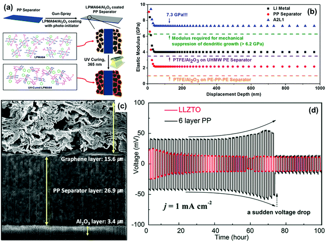 | ||
| Fig. 4 (a) Schematic depiction for the fabrication of hybrid composite coated separators. (b) Nanoindentation-derived elastic moduli of the pristine PP separator, A2L1 hybrid composite separator, PTFE/Al2O3-coated UHMWPE composite separator, and PTFE/Al2O3-coated PE–PP–PE/Al2O3 composite separator. Reproduced with permission from ref. 70. Copyright 2016, American Chemical Society. (c) Cross-sectional view of the dual-functional graphene/PP/Al2O3 (DF-GPA) separator. Reproduced with permission from ref. 77. Copyright 2017, Wiley. (d) Galvanostatic charge/discharge curves of symmetric Li–Li cells with the LLZTO separator and the 6-layer PP separator (areal capacity: 1 mA h cm−2). Reproduced with permission from ref. 79. Copyright 2018, The Royal Society of Chemistry. | ||
In addition to functional coatings, porous ceramic membranes have also been directly employed as functional separators capable of excellent mechanical properties. Qu et al. studied three types of porous ceramic separators (garnet type Li6.4La3Zr1.4Ta0.6O12 (LLZTO), Y0.16Zr0.84O2−δ (YSZ), and Al2O3) in detail for evaluating their ability to inhibit lithium dendrites.79 As shown in Fig. 4d, the Li–Li cell equipped with the LLZTO separator could maintain stable cycling for 100 h under a current density of 1 mA cm−2, indicating the excellent stability of the lithium metal electrode. On the other hand, the cell with a 6-layer PP separator presented an abrupt voltage drop after continuous cycling for 75 h, which was ascribed to the short-circuit caused by lithium dendrites piercing the separator. Thus, the mechanically stiff ceramic separators possessed high mechanical strength to block lithium dendrites penetration, demonstrating a promising prospect in developing high-performance LMBs.
Polymers are another ideal candidate for the construction of functional separators with enhanced mechanical property. Liu's group developed a non-porous soft rubber separator with a wide elastic deformation range and confirmed that dendrite penetration could be prevented even if the separator was softer by a factor of 104.80 The traditional PP separator could not accommodate uneven volume change caused by dendrite growth and its ∼30 nm open pores would concentrate the current to induce heterogeneous diffusion-limited growth and penetration (Fig. 5a). In contrast, there was no risk of “chasing the current” through the open pores of a fully dense and uniform elastomeric separator. When a separator is deformed elastically, it automatically exerts a compressive stress against the lithium anodes and resists local volume expansion to maintain uniform interfacial contact and limit the deterioration of the lithium morphology (Fig. 5b). Therefore, non-porous rubbery separators are desirable in the construction of high-energy batteries with lithium metal anodes. Recently, Liu et al. fabricated an ultra-strong porous PEEK separator via thermally induced phase separation using a binary diluent with controllable component (Fig. 5c).81 The PEEK separator demonstrated superior mechanical performance in both tensile and puncture strength tests compared with the conventional PE separator (Fig. 5d and e). Moreover, the novel separator developed in this work also featured the advantages of excellent thermal stability and electrolyte wettability, which is a good candidate fpr suppressing lithium dendrites in LMBs.
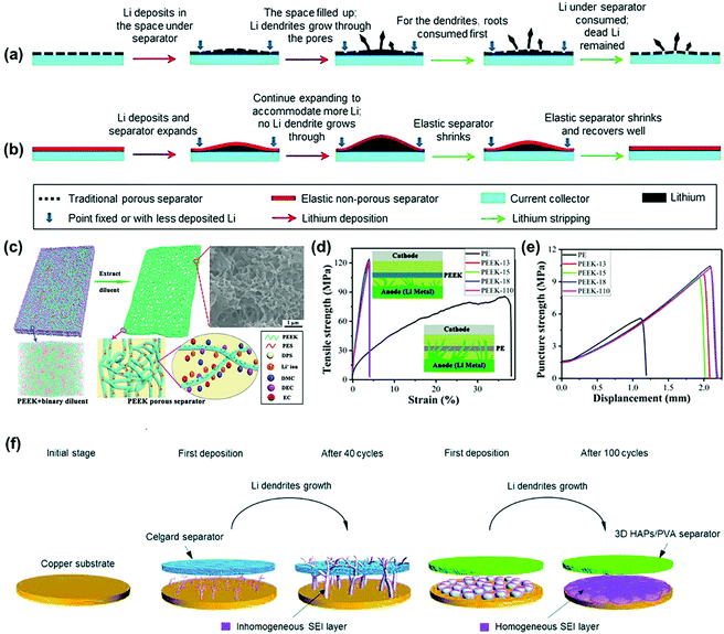 | ||
| Fig. 5 Schematics of the behaviors of a traditional plastic porous separator (a) and a designed non-porous elastomeric solid–electrolyte separator (b) interacting with uneven lithium deposition at high current densities and large areal capacities. Reproduced with permission from ref. 80. Copyright 2017, The Royal Society of Chemistry. (c) Schematic illustration of the fabrication of the PEEK porous separator. The insets represent the mesoscopic morphology from mesoscopic dissipative particle dynamics (DPD) simulation and the transportation of lithium ion in the separator. (d) Tensile strength and (e) puncture strength of PE and PEEK separators. The inset is the schematic illustration of mechanical suppression preventing lithium dendrite formation with PE and PEEK separators. Reproduced with permission from ref. 81. Copyright 2019, American Chemical Society. (f) Schematic illustration showing the bare copper substrate and the growth process of dendritic Li on the surface of the copper substrate with the Celgard separator and the 3D HAPs/PVA separator. Reproduced with permission from ref. 82. Copyright 2019, The Royal Society of Chemistry. | ||
Furthermore, Wang et al. prepared a robust and flexible 3D hydroxyapatite (HAPs)/polyvinyl alcohol (PVA) separator for inhibiting lithium dendrites.82 As illustrated in Fig. 5f, there was a significant difference in the morphology of Li deposited on the copper substrate between the utilization of the 3D HAPs/PVA separator and the Celgard one. The Celgard separator with a low modulus could not prevent the continuous growth of dendritic Li. As a result, repeating the construction/repair process of the SEI layer led to the constant consumption of the electrolyte and inhomogeneous formation of the SEI layer, which in turn caused a low Coulombic efficiency or even short-circuit of the battery. In comparison, the 3D HAPs/PVA separator with a high modulus could efficiently retard the growth of lithium dendrites in a perpendicular direction, thus contributing to a smaller SEI layer specific surface area as well as non-dendritic lithium. During continuous cycling, the SEI layer tended to become smooth and uniform, which effectively suppressed the growth of lithium dendrites in the LMBs. The above robust functional separators effectively prevented the short-circuit of the batteries by suppressing lithium dendrites but it is difficult to use them for constructing “dendrite-free” LMBs.
To prevent being punctured by lithium dendrites, the separator is endowed with superior mechanical property through the functionalization of special materials with high elastic modulus such as ceramics and polymers. This strategy is simple and easy to implement. The functional separators with high mechanical strength are more suitable for resisting the long dendrites. However, such a strategy cannot fundamentally suppress the formation of lithium dendrites and their outgrowth of “dead Li”. It is difficult for high strength functional separators to solve some key problems in LMB such as capacity fading and decrease in the Coulomb efficiency. Therefore, it is of significance to inhibit the growth of lithium dendrites by employing well-designed functional separators and thus improve the electrochemical performance of LMBs.
5.2. Promoting homogeneous lithium deposition
It is well-accepted that the growth of lithium dendrites could be inhibited by homogeneous lithium deposition on the lithium metal anode in LMBs. In recent years, many functional separators have been developed to uniformly disperse the Li+ flux that reached the surface of lithium metal. The typical functionalization strategy includes constructing ordered pores on the separator and improving the affinity of the separator on lithium metal.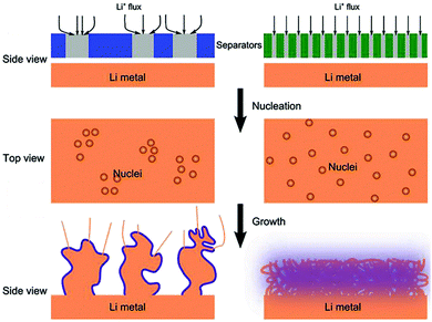 | ||
| Fig. 6 Schematic illustrations of the influence of the separator pore distribution on the morphology of the Li deposit. Reproduced with permission from ref. 83. Copyright 2018, Wiley. | ||
| Materials | Preparation methods | Pore structure | Electrolytes | Performance (Li–Li cells) | Ref. |
|---|---|---|---|---|---|
| AAO membrane | Electrochemical anodic oxidation | High density, uniform, nanometer-sized pores (approximately 200 nm in diameter) | 1 M LiTFSI in DME | ∼29 h (0.5 mA) | 85 |
| AAO with a pore diameter of 200 nm onto PP (AP) | Assembling | Uniform porous structure of AP | 1.2 M LiPF6 in EC/EMC (3![[thin space (1/6-em)]](https://www.rsc.org/images/entities/char_2009.gif) : :![[thin space (1/6-em)]](https://www.rsc.org/images/entities/char_2009.gif) 7 wt%) 7 wt%) |
∼310 h (0.25 mA cm−1, 0.5 mA h cm−1) | 86 |
| ∼109 h (1 mA cm−1, 0.5 mA h cm−1) | |||||
| ∼105 h (1 mA cm−1, 1 mA h cm−1) | |||||
| ∼102 h (1 mA cm−1, 2 mA h cm−1) | |||||
| ∼44 h (2 mA cm−1, 0.5 mA h cm−1) | |||||
| MOF@Poly(vinylidene fluoride-co-hexafluoropropylene) (PVDF-HFP) | Vacuum filtration | Uniformly ordered pores with pore sizes around 9 Å of MOF particles | 1 M LiTFSI and 0.2 wt% LiNO3 in DOL/DME (1![[thin space (1/6-em)]](https://www.rsc.org/images/entities/char_2009.gif) : :![[thin space (1/6-em)]](https://www.rsc.org/images/entities/char_2009.gif) 1 by volume) 1 by volume) |
>1000 h (2 mA cm−1, 1 mA h cm−1) | 87 |
| >1000 h (10 mA cm−1, 5 mA h cm−1) | |||||
| A safe inorganic separator based on hydroxyapatite (HAP) nanowires | Vacuum suction filtration | Evenly distributed pores of the HAP separator | 1 M LiPF6 in EC/DEC (1![[thin space (1/6-em)]](https://www.rsc.org/images/entities/char_2009.gif) : :![[thin space (1/6-em)]](https://www.rsc.org/images/entities/char_2009.gif) 1 by volume) with 5% FEC as the additive 1 by volume) with 5% FEC as the additive |
>650 h (1 mA cm−1, 1 mA h cm−1) | 88 |
| >350 h (2 mA cm−1, 1 mA h cm−1) | |||||
| >150 h (4 mA cm−1, 1 mA h cm−1) | |||||
| >1200 h (0.5 mA cm−1, 1 mA h cm−1) without FEC | |||||
| >450 h (1 mA cm−1, 1 mA h cm−1) without FEC | |||||
| >180 h (2 mA cm−1, 1 mA h cm−1) without FEC | |||||
| A tri-layer cellulose nanofibers (CNFs)/PE/CNFs separator | Straightforward paper-making and lamination | Homogeneous mesopore distribution in the CNFs layers | LP40 (i.e., 1 M LiPF6 in EC/DEC (1![[thin space (1/6-em)]](https://www.rsc.org/images/entities/char_2009.gif) : :![[thin space (1/6-em)]](https://www.rsc.org/images/entities/char_2009.gif) 1 by volume)) 1 by volume)) |
396 h (0.65 mA cm−1, 0.65 mA h cm−1) | 83 |
| 85 h (1.3 mA cm−1, 1.3 mA h cm−1) | |||||
| A sandwich-structured separator (CGC separator) composed of two 2.5 μm-thick CNF surface layers and an intermediate 15 μm-thick glass microfiber (GMF) and the CNF composite layer | Vacuum filtration | Homogeneous pore distribution of CGC separator | LP40 (i.e., 1 M LiPF6 in EC/DEC (1![[thin space (1/6-em)]](https://www.rsc.org/images/entities/char_2009.gif) : :![[thin space (1/6-em)]](https://www.rsc.org/images/entities/char_2009.gif) 1 by volume)) 1 by volume)) |
>620 h (0.65 mA cm−1, 0.65 mA h cm−1) | 89 |
| >250 h (1 mA cm−1, 1 mA h cm−1) | |||||
| Over-oxidized polypyrrole (OPPy) separator | Two-step overoxidation | Homogeneous pore structure of the OPPy separator | LP40 (i.e., 1 M LiPF6 in EC/DEC (1![[thin space (1/6-em)]](https://www.rsc.org/images/entities/char_2009.gif) : :![[thin space (1/6-em)]](https://www.rsc.org/images/entities/char_2009.gif) 1 by volume)) 1 by volume)) |
>600 h (0.5 mA cm−1, 0.5 mA h cm−1) | 84 |
| A multiscale structural PVDF-HFP/poly-m-phenyleneisophthalamide (PMIA)-based gel polymer electrolyte (GPE) embedded with tetrabutylammonium hexafluorophosphate (TBAHP) particles (T/F-P separator) | Electrospinning | Uniform pore distribution of T/F-P separator | 1 M LiPF6 in EC/DEC/EMC (1![[thin space (1/6-em)]](https://www.rsc.org/images/entities/char_2009.gif) : :![[thin space (1/6-em)]](https://www.rsc.org/images/entities/char_2009.gif) 1 1![[thin space (1/6-em)]](https://www.rsc.org/images/entities/char_2009.gif) : :![[thin space (1/6-em)]](https://www.rsc.org/images/entities/char_2009.gif) 1 by volume) 1 by volume) |
>500 h (1 mA cm−1, 1 mA h cm−1) | 90 |
| A PVDF-HFP/Li-montmorillonite (MMT) composite separator | Electrophoretic deposition | The parallel ion channels in the Li-MMT/PVDF-HFP separator | 1 M LiPF6 in EC/DMC/EMC (1![[thin space (1/6-em)]](https://www.rsc.org/images/entities/char_2009.gif) : :![[thin space (1/6-em)]](https://www.rsc.org/images/entities/char_2009.gif) 1 by volume) 1 by volume) |
385 h (0.5 mA cm−1) | 91 |
| >200 h (1 mA cm−1) |
AAO nanoporous membranes have been widely used as battery separators in recent years, mainly due to their attractive advantages including regular and high-density nanochannels, tunable pore size, superior mechanical property, and thermal stability.92–95 For instance, Kang and co-workers applied AAO nanoporous membrane as a separator for the construction of the symmetric Li|Li cell shown in Fig. 7a, which demonstrated a better cycle stability compared with the commercial PP separator during the lithium plating/stripping process (Fig. 7b).85 When applied in Li–O2 batteries, the AAO functional separator could also deliver a superior cycling performance compared to the routine separator (Fig. 7c), indicating the applicability for the suppression of lithium dendrite growth. To further understand the homogeneous lithium deposition promoted by AAO separator, Wang et al. developed a novel composite separator for LMBs by combining the AAO nanoporous membrane with the pristine PP separator (AP).86 Owing to the ordered pore structure, high mechanical strength, and electrolyte retention, AP-based symmetric Li–Li cells exhibited an enhanced cycling performance compared with the cells based on the pristine PP separator. Furthermore, the LMB (Li-NCM523) equipped with the AP separator also demonstrated a better electrochemical performance than that with the PP separator, such as delayed capacity fading and a smaller voltage plateau change (Fig. 7d). This was mainly ascribed to the less electrolyte consumption caused by the repressed lithium dendrites when introducing the AP separator. During the charging/discharging cycle, the accumulation of “dead Li” will form a corrosion layer at the electrode/electrolyte interface. In the Li–Li cell, the utilization of the AP separator contributed to a thinner corrosion layer and a better interfacial adhesion compared to that with the PP separator (Fig. 7e–g). Although the separators functionalized by AAO could improve the performance of LMB, their inhibiting effects on lithium dendrite growth are not very impressive. Thus, it is still a challenge to develop high-performance functional separators to meet the performance requirements of high-energy batteries.
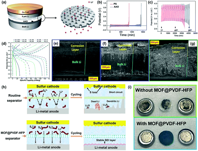 | ||
| Fig. 7 (a) Schematic representation of the coin cell with AAO. (b) Chronopotentiometry results of the coin cells containing PP and AAO separators. 1 M LiTFSI in DME was used as the electrolyte. (c) The galvanostatic cycle behavior of the Li–O2 cells without (red line) and with the AAO (blue line) separator. 1 M LiNO3 in DMAc was used as the electrolyte. The cycling was performed with 0.5 C (±0.5 mA for 1000 s) capacity cutoff. Reproduced with permission from ref. 85. Copyright 2014, The Royal Society of Chemistry. (d) Charge–discharge curves of Li-NCM523 coin cells at different cycles. Cross-sectional SEM images of the Li-metal electrode in the symmetric Li–Li cells using (e) AP with Li close to AAO, (f) AP with Li close to PP, and (g) PP after 100 cycles under the current density of 1 mA cm−2 and the cycling capacity of 0.5 mA h cm−2 at a temperature of 20 °C. Reproduced with permission from ref. 86. Copyright 2019, American Chemical Society. (h) Schematic for Li–S batteries with different separators. (i) Digital photos of the detached Li–Li symmetric cells with different separators after 1000 cycles at a current density of 2 mA cm−2 with areal-capacity of 1 mA h cm−2. Reproduced with permission from ref. 87. Copyright 2018, Wiley. | ||
MOFs and their derivatives play key roles in electrochemical energy storage and conversion because their well-defined sub-nanoscale pores provide several channels for the passage of Li+.96–98 Most of the earlier studies are focused on the utilization of MOFs in the fabrication of electrode materials for advanced energy devices. In recent years, MOF materials have attracted significant interest in the functionalization of separators for high-energy LMBs. In some LSBs, functional separators based on MOFs could address the critical issues of both lithium dendrites and the shuttle effect. For example, He et al. prepared a flexible MOF-based separator (MOF@PVDF-HFP) using a facial vacuum filtration strategy to settle the lithium dendrite and the shuttle effect issues simultaneously in LSBs.87 Compared with the routine separator, the MOF@PVDF-HFP separator could achieve more stable Li plating/striping by utilizing the uniform sub-nanochannels to promote homogeneous Li deposition (Fig. 7h). Furthermore, the nano-confined pores in the functional separator could also act as an effective physical barrier in order to prevent the shuttle effect of the dissolved polysulfides. Consequently, the lithium metal anode obtained from the cell equipped with the MOF@PVDF-HFP separator demonstrated a flat surface with a bright metallic luster after 1000 charging/discharging cycles at a current density of 2 mA cm−2 (Fig. 7i). On the other hand, the lithium metal anode was seriously pulverized in the cell without the MOF@PVDF-HFP separator, indicating the critical roles of the well-defined pores of MOFs for a high-performance battery.
Self-standing nanofiber membrane is another good choice to develop functional separators towards the mitigation of lithium dendrite growth because of the uniform and high-density pores. For instance, the hydroxyapatite Ca10(PO4)6(OH)2 (HAP) nanowire separator was synthesized using vacuum suction filtration by Rao and co-workers.88 For comparison, the HAP and routine PP separators were separately employed to construct the LMBs with LiMnO2 cathodes and lithium metal anodes. In case of the PP separator, the lithium dendrite growth and Mn dissolution facilitated by HF in the electrolyte can cause poor electrochemical performance and serious safety issues (Fig. 8a). On the other hand, for the HAP separator, evenly distributed pores promoted uniformly arranged Li+ on the surface of lithium anode and thus reduced the dendrite growth (Fig. 8b). On the other hand, the porous structure of the HAP separator could act as a buffer layer to accommodate the lithium dendrites, which further prevented the dendrites from penetrating through the separator. Moreover, Ca2+ in the HAP separator could bond with F− from the electrolyte to reduce the dissolution of the Mn element in the electrode materials, which in turn improved the cycling stability of the LMB at a temperature below 55 °C (Fig. 8c). Recently, Pan et al. constructed a sandwich-structured separator (CGC) comprised of two cellulose nanofiber (CNF) surface layers and a glass microfiber (GMF) as well as a CNF composite layer intermediate.89 The intertwined nanofiber network produced high-density nanopores with a diameter of about ten nanometers (Fig. 8d). When integrated into the Li–Cu cell, the CGC separator could maintain a rather constant coulombic efficiency (CE) of about 90% over 80 cycles; however, the commercial Celgard separator-based cell demonstrated obvious fluctuations in the CE only after 30 cycles (Fig. 8e). This work further proved that the use of a separator with homogeneous pore distribution could significantly improve the cycling performance of the LMBs. In the study by Wang and co-workers,84 a novel separator based on porous conducting polymers (CPs) paper was prepared by converting conductive polypyrrole (PPy) into an electronically insulating membrane via a two-step over-oxidation procedure. The over-oxidized paper (OPPy) separator had a homogeneous mesoporous structure with the pore size ranging from 10 to 70 nm, which led to both uniform deposition and dissolution of lithium on the electrode (Fig. 8f). As shown in Fig. 8g, the Li|OPPy|Li cell presented a stabilized voltage during long-term galvanostatic cycling over 600 h (over 300 cycles) at a current density of 0.25 mA cm−2. In contrast, the overpotential of the Li|PE|Li cell increased significantly over a period of 350 h (175th cycle) of operation.
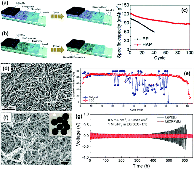 | ||
| Fig. 8 The schematic illustration of Mn dissolution and Li plating for the cell with (a) PP and (b) HAP separators. (c) Cycling performance of the LiMn2O4 half cells at 55 °C; the current density is 0.5 C. Reproduced with permission from ref. 88. Copyright 2020, The Royal Society of Chemistry. (d) SEM images of the surface CNF layer of the CGC separator. (e) The CE as a function of the cycle number for the Cu|Li cells equipped with a Celgard or CGC separator. The Li deposition step was carried out for one hour at a current density of 0.75 mA cm−2, while the Li oxidation step was carried out at 0.75 mA cm−2 either for one hour or until the cell voltage reached 1 V. Reproduced with permission from ref. 89. Copyright 2018, Elsevier. (f) SEM images of OPPy. (g) Voltage–time profiles for symmetric Li–Li cells containing either a PE or an OPPy separator and a LP40 electrolyte using a fixed reduction or oxidation charge of 0.5 mA h cm−2 and a current density of 0.5 mA cm−2. Reproduced with permission from ref. 84. Copyright 2018, Elsevier. | ||
Ryou et al. proposed that a heterogeneous interface between the lithium metal electrode and the electrolyte causes various detrimental phenomena because of the local enhancement of Li+ flux.99 To construct a homogeneous interface, the commercial PE separator was coated with a mussel-inspired polydopamine layer via dip-coating to improve the performance of the lithium metal anode. On the one hand, the functionalization of the polydopamine coating improved the electrolyte infiltration of the PE separator (Fig. 9a), thus contributing to the homogeneous distribution of Li+ flux over the entire lithium metal during cycling (Fig. 9b). On the other hand, the catechol moieties attached to the polydopamine backbones have extraordinarily strong adhesion to versatile substrates, which generated a strong adhesive interaction between the Li metal electrodes and the separators that relieved the local surface tension (Fig. 9c). Thus, the formation and growth of lithium dendrites could be effectively suppressed. Similarly, Shin's group modified the routine PE separator with a coating of nitrogen and sulfur co-doped graphene (NSG) nanosheets.69 When applied in the Li/LiNi0.8Co0.15Al0.05O2 cell, the NSG separator demonstrated superior cycling stability than both pristine PE and GO separators (Fig. 9d), which was ascribed to the suppression of dendrite growth on the lithium metal anode. After the functionalization, the surface of the PE separator covered with NSG carried negative charges owing to lone pair of electrons in the heteroatom dopants. As a result, the interfacial interaction between the separator and lithium metal was significantly enhanced because of their strong electrostatic attraction (Fig. 9e), which was further confirmed by a much higher sliding force (7.6 mN) between lithium foil and the NSG separator than that with the PE separator (Fig. 9f). Such an enhanced adhesion could effectively release the surface tension of the Li metal anode in order to suppress the initiation of dendrite growth.
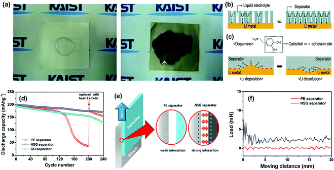 | ||
| Fig. 9 (a) Digital-camera images after pouring liquid electrolyte [1 M LiClO4–EC/PC (1/1 by weight)] onto a bare PE separator (left) and a polydopamine-treated PE separator (right). (b) The effect of the separators with poor wettability (left) and good wettability (right) on the uniform Li-ion flux. (c) The molecular structure of dopamine, as well as the effect of the adhesive properties of the separators onto Li-metal surfaces during Li deposition (left) and Li dissolution (right). Enhanced adhesion by catecholic interactions (red dots) releases (arrows) the surface tension of Li metal during battery cycling and thus suppresses Li-dendrite growth. Reproduced with permission from ref. 99. Copyright 2012, Wiley. (d) Discharge capacities of the Li/LiNi0.8Co0.15Al0.05O2 cells assembled with different separators as a function of the cycle number. (e) Schematic illustration of the shear tests conducted to examine the interfacial interaction between the lithium electrode and the separator. (f) Shear force measured between the lithium electrode and the separator. Reproduced with permission from ref. 69. Copyright 2015, American Chemical Society. | ||
Some materials with high lithium affinity have been applied for the construction of self-standing separators. Kim et al. prepared a regenerated chitin fiber (Chiber) separator for inhibiting lithium dendrites based on the highly physicochemical affinity between chitin and Li+.100 When applied in a Swagelok-type Li–O2 battery, the cycle lifetime was approximately twice as long as that using the conventional glass microfiber filter (GF) separator (Fig. 10a and b). Interestingly, Ma and co-workers developed a promising separator candidate with good lithium affinity by extracting pristine eggshell membranes (ESMs) from waste eggshells, and then fabricated large-area and flat nanoporous regenerated ESMs (RESM) to overcome the curved shape and limited size of raw ESM.101 The RESM separator had a negative charge layer throughout the surface, which could strongly adhere to the positively charged lithium metal, thus promoting homogeneous Li deposition (Fig. 10c–e). Moreover, compared with the micro-scale pores of the Celgard separator, the growth of large-sized lithium dendrites could be greatly suppressed by the nano-scale porosity of the RESM separator. This study provides a promising route to convert bio-wastes into functional separators and settle some critical issues in high-energy batteries.
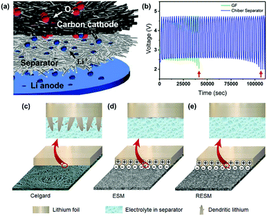 | ||
| Fig. 10 (a) Schematic representation of the Li–O2 cell architecture comprised of three layers: 5 μm Li anode/separator/carbon cathode. (b) The galvanostatic cycle endurance of GF (green) and Chiber (blue) separator contained Li–O2 batteries. Reproduced with permission from ref. 100. Copyright 2017, American Chemical Society. Schematic illustrations of dendritic lithium growth on the lithium metal electrodes in the presence of (c) commercial Celgard, (d) ESM, and (e) RESM separators, respectively. Reproduced with permission from ref. 101. Copyright 2018, Elsevier. | ||
Graphene oxide (GO) film has also been used to construct functional separators for addressing the problem of lithium dendrite in LMBs. Recently, Li and co-workers reported the preparation of a bilayer composite separator through the simple blade-coating of polyacrylamide-grafted GO layer onto commercial PP separators (GO-g-PAM@PP).102 When applying GO-g-PAM@PP (Fig. 11a), the robust GO backbones of the molecular brushes could enhance the mechanical strength and the hairy PAM chains on the GO surfaces with a large quantity of polar groups, including C![[double bond, length as m-dash]](https://www.rsc.org/images/entities/char_e001.gif) O and N–H bonds, could offer abundant lithiophilic sites for the efficient adhesion and homogeneous distribution of Li+ at the molecular level. In addition, the interspaces between the stacked molecular brushes could provide fast pathways for the diffusion of electrolytes. The above advantages of GO-g-PAM@PP will lead to molecular-level homogeneous and fast Li+ flux on the surface of the electrodes and dendrite-free uniform lithium deposition with high coulombic efficiencies and ultralong-term reversible Li plating/stripping under very high current densities. As a result, the LMB equipped with the GO-g-PAM@PP separator demonstrated excellent stability of lithium plating/stripping for over 1900 h at an extremely high current density of 20 mA cm−2 (Fig. 11b). The areal capacity reached up to 5 mA h cm−2, which was much higher than that of commercial batteries (3 mA h cm−2). This work created possibilities for constructing advanced dendrite-free LMBs by the means of separator functionalization.
O and N–H bonds, could offer abundant lithiophilic sites for the efficient adhesion and homogeneous distribution of Li+ at the molecular level. In addition, the interspaces between the stacked molecular brushes could provide fast pathways for the diffusion of electrolytes. The above advantages of GO-g-PAM@PP will lead to molecular-level homogeneous and fast Li+ flux on the surface of the electrodes and dendrite-free uniform lithium deposition with high coulombic efficiencies and ultralong-term reversible Li plating/stripping under very high current densities. As a result, the LMB equipped with the GO-g-PAM@PP separator demonstrated excellent stability of lithium plating/stripping for over 1900 h at an extremely high current density of 20 mA cm−2 (Fig. 11b). The areal capacity reached up to 5 mA h cm−2, which was much higher than that of commercial batteries (3 mA h cm−2). This work created possibilities for constructing advanced dendrite-free LMBs by the means of separator functionalization.
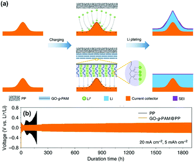 | ||
| Fig. 11 (a) Schematics showing Li deposition on an electrode with a PP separator and a GO-g-PAM@PP separator. (b) Voltage–time profiles of Li plating/stripping processes with a cycling capacity of 5 mA h cm−2 at 20 mA cm−2 in symmetric Li–Li cells with GO-g-PAM@PP and PP separators. Reproduced with permission from ref. 102. Copyright 2019, Nature. | ||
From the mechanism, the achievement of homogeneous lithium deposition using functional separators could effectively suppress the growth of lithium dendrites. On the basis of this strategy, functional separators are usually constructed by creating ordered pore structures or improving the affinity on lithium metal anode. Thus, there are abundant material systems and preparation methods for separator functionalization. Some available materials have the advantage of high mechanical property, which could provide both robust physical barrier and homogeneous lithium deposition. Except for optimizing the lithium deposition process, the regulation of the nucleation process of lithium dendrites could further achieve dendrite-free LMBs. Therefore, some other strategies of separator functionalization are desired to create dendrite-free lithium metal anodes for LMBs.
5.3. Regulating ionic transport
According to Sand's formula, the free movement of anions (high transference number) near the lithium metal is a vital factor responsible for the nucleation of lithium dendrites. Moreover, the uncontrolled transport of anions could give rise to some other issues such as unwanted joule heat and battery polarization.103–105 Thus, controlling anion transport is of great significance to develop high-performance dendrite-free LMBs. As the passages for ion passage between the two electrodes, the separators could be endowed with ionic transport regulation behaviors through reasonable functional modifications. Considering the competitive relationship of the anions and Li+ transport in the electrolyte, the Li+ selective separator with a high tLi+ has the prospect of becoming a powerful tool for inhibiting the nucleation of lithium dendrites fundamentally. In recent years, some advances and progresses have been made in the development of Li+ selective separators for suppressing lithium dendrites, and the typical construction strategies including anion immobilization, size sieving, and electrostatic interaction. Table 2 summarizes some typical examples of Li+ selective separators for suppressing lithium dendrites.| Materials | Preparation methods | Electrolyte | t Li+ | Performance (Li–Li cells) | Ref. |
|---|---|---|---|---|---|
| The electrolyte-filled triblock copolymer poly (styrene-block-isoprene-block-sulfonated isoprene) | Anionic polymerization and the succeeding analogous chemistry, solvent casting, and immersing the liquid electrolyte | 1 M LiPF6 in EC/DEC/EMC (4![[thin space (1/6-em)]](https://www.rsc.org/images/entities/char_2009.gif) : :![[thin space (1/6-em)]](https://www.rsc.org/images/entities/char_2009.gif) 3 3![[thin space (1/6-em)]](https://www.rsc.org/images/entities/char_2009.gif) : :![[thin space (1/6-em)]](https://www.rsc.org/images/entities/char_2009.gif) 3 by volume) 3 by volume) |
0.92 | >500 h (1 mA cm−1, 3 mA h cm−1) | 106 |
| Polyethylenimine (poly(acrylic acid)/poly(ethylene oxide))3-modified PE | Layer-by-layer assembly | 1 M LiPF6 in EC/DMC | 0.48 | 450 h (1 mA cm−1, 1 mA h cm−1) | 107 |
| 200 h (2 mA cm−1, 1 mA h cm−1) | |||||
| Polybenzimidazole-based polymer electrolytes with ethanol as the coagulation bath | Non-solvent induced phase separation process | 1 M LiPF6 in EC/DMC (1![[thin space (1/6-em)]](https://www.rsc.org/images/entities/char_2009.gif) : :![[thin space (1/6-em)]](https://www.rsc.org/images/entities/char_2009.gif) 1 by volume) 1 by volume) |
0.76 | >400 h (0.5 mA cm−1) | 108 |
| MOF-Poly(vinyl alcohol) composite membranes with 1 M LiPF6 in EC/DEC | Electrospinning | 1 M LiPF6 in EC/DEC (1![[thin space (1/6-em)]](https://www.rsc.org/images/entities/char_2009.gif) : :![[thin space (1/6-em)]](https://www.rsc.org/images/entities/char_2009.gif) 1 by volume) 1 by volume) |
0.59 | >400 h (0.5 mA cm−2, 0.5 mA h cm−1) | 68 |
| NH2-MIL-125(Ti)-coated Celgard | Doctor blading | 1 M LiTFSI in DOL/DME (1![[thin space (1/6-em)]](https://www.rsc.org/images/entities/char_2009.gif) : :![[thin space (1/6-em)]](https://www.rsc.org/images/entities/char_2009.gif) 1 by volume) with 2% LiNO3 1 by volume) with 2% LiNO3 |
0.64–0.78 | 1200 h (1 mA cm−2, 1 mA h cm−2) | 109 |
| Schiff-base covalent organic frameworks/PP | Coating | 1 M LiTFSI in DOL/DME (1![[thin space (1/6-em)]](https://www.rsc.org/images/entities/char_2009.gif) : :![[thin space (1/6-em)]](https://www.rsc.org/images/entities/char_2009.gif) 1 by volume) with 2 wt% LiNO3 and 1 M LiPF6 in EC/DEC (1 1 by volume) with 2 wt% LiNO3 and 1 M LiPF6 in EC/DEC (1![[thin space (1/6-em)]](https://www.rsc.org/images/entities/char_2009.gif) : :![[thin space (1/6-em)]](https://www.rsc.org/images/entities/char_2009.gif) 1 by volume) 1 by volume) |
0.77 ± 0.01 | >1000 h (0.5 mA cm−2, 0.5 mA h cm−1) | 110 |
| >1000 h (1 mA cm−2, 1 mA h cm−1) | |||||
| Mesoporous silica thin films with perpendicular nanochannels on the AAO membrane | Evaporation induced self-assembly | 1 M LiTFSI in DOL/DME (1![[thin space (1/6-em)]](https://www.rsc.org/images/entities/char_2009.gif) : :![[thin space (1/6-em)]](https://www.rsc.org/images/entities/char_2009.gif) 1 by volume) and 1 M LiPF6 in EC/DEC (1 1 by volume) and 1 M LiPF6 in EC/DEC (1![[thin space (1/6-em)]](https://www.rsc.org/images/entities/char_2009.gif) : :![[thin space (1/6-em)]](https://www.rsc.org/images/entities/char_2009.gif) 1 by volume) 1 by volume) |
— | 1 M LiTFSI in DOL/DME (1![[thin space (1/6-em)]](https://www.rsc.org/images/entities/char_2009.gif) : :![[thin space (1/6-em)]](https://www.rsc.org/images/entities/char_2009.gif) 1 by volume): 1 by volume): |
111 |
| >2000 h (0.5 mA cm−2, 0.25 mA h cm−1) | |||||
| >2000 h (2 mA cm−2, 1 mA h cm−1) | |||||
| >2000 h (3 mA cm−2, 1.5 mA h cm−1) | |||||
| >1600 h (10 mA cm−2, 5 mA h cm−1) | |||||
| >400 h (20 mA cm−2, 10 mA h cm−1) | |||||
1 M LiPF6 in EC/DEC (1![[thin space (1/6-em)]](https://www.rsc.org/images/entities/char_2009.gif) : :![[thin space (1/6-em)]](https://www.rsc.org/images/entities/char_2009.gif) 1 by volume): 1 by volume): |
|||||
| >2000 h (2 mA cm−2, 1 mA h cm−1) | |||||
| >1600 h (5 mA cm−2, 2.5 mA h cm−1) | |||||
| Gelatin nanofabric | Electrospinning | 1 M LiTFSI in mixture of DOL and DME (1![[thin space (1/6-em)]](https://www.rsc.org/images/entities/char_2009.gif) : :![[thin space (1/6-em)]](https://www.rsc.org/images/entities/char_2009.gif) 1 by volume), and 2 wt% LiNO3 as additive 1 by volume), and 2 wt% LiNO3 as additive |
0.73 | >1000 h (0.5 mA cm−2, 0.5 mA h cm−1) | 112 |
| Poly(acrylonitrile-co-lithium acrylate-co-butyl acrylate)/PP | Soap-free emulsion polymerization and a simple dip-annealing | 1 M LiPF6 in [V(EC)![[thin space (1/6-em)]](https://www.rsc.org/images/entities/char_2009.gif) : :![[thin space (1/6-em)]](https://www.rsc.org/images/entities/char_2009.gif) V(DME) V(DME)![[thin space (1/6-em)]](https://www.rsc.org/images/entities/char_2009.gif) : :![[thin space (1/6-em)]](https://www.rsc.org/images/entities/char_2009.gif) V(EMC) = 1 V(EMC) = 1![[thin space (1/6-em)]](https://www.rsc.org/images/entities/char_2009.gif) : :![[thin space (1/6-em)]](https://www.rsc.org/images/entities/char_2009.gif) 1 1![[thin space (1/6-em)]](https://www.rsc.org/images/entities/char_2009.gif) : :![[thin space (1/6-em)]](https://www.rsc.org/images/entities/char_2009.gif) 1] 1] |
0.525 | 800 h (1 mA cm−2, 1 mA h cm−1) | 113 |
| Celgard®silicone nanofilaments (SNFs)/polydopamine (PDA) | Successive deposition | 1 M LiTFSI in the DOL/DEM mixture (1![[thin space (1/6-em)]](https://www.rsc.org/images/entities/char_2009.gif) : :![[thin space (1/6-em)]](https://www.rsc.org/images/entities/char_2009.gif) 1, v/v) 1, v/v) |
0.75 | >2300 h (1 mA cm−2, 1 mA h cm−1) | 114 |
| >600 h (10 mA cm−2, 1 mA h cm−1) |
In order to control anion transport, Liu et al. synthesized mechanically robust non-porous functional separators based on triblock copolymers of polystyrene-block-isoprene-block-sulfonated isoprene (SII).106 The SII molecule is made up with three functional units, a terminal sulfonate polyisoprene (sPI) segment for anion immobilization, a central ductile polyisoprene (PI (1,4)) segment for flexibility and processability, and another terminal polystyrene (PS) segment for the high mechanical strength of the separator (Fig. 12a). Such a well-designed functional separator demonstrated excellent cycling performance during the Li plating/striping process. In the Li/SII–LE/Li cell, the surface of the lithium metal anode was smooth and flat even after galvanostatic cycling for 245 h (Fig. 12b), indicating the efficient suppression of dendrite formation by the functional separator with anion immobilization property. Jin and co-workers modified the routine PE separator with a unique polymer multilayer composed of polyethylenimine (PEI), PAA, and poly(ethylene oxide) PEO (PEI(PAA/PEO)3) by utilizing layer-by-layer assembly (Fig. 12c).107 The improved electrolyte affinity and segmental motions of the polymer PEO chains are the main reasons for the enhancement of tLi+ (from 0.37 to 0.48). Thus, the PE separator functionalized by PEI(PAA/PEO)3 could decrease both RSEI and Rct of the LiCoO2/Li cell during charge/discharge cycles (Fig. 12d) because the suppression of lithium dendrites contributed to a more stable SEI layer formation on the lithium metal anode and a faster charge transfer at the electrolyte/electrode interface. Moreover, the functionalization of PEI(PAA/PEO)3 could also improve the electrolyte infiltration of the pristine PE separator, thus increasing the Li+ conductivity of the separator-liquid electrolyte system from 0.36 mS cm−1 to 0.45 mS cm−1. Besides, a novel porous polybenzimidazole (PBI) separator was developed to control anion transfer in the LMB and its influence mechanism on the ionic transport was further studied in detail.108 Based on the density functional theory (DFT) calculations, the highest occupied molecular orbital (HOMO) of the electron-rich imidazole ring in PBI matched well with the lowest unoccupied molecular orbital (LUMO) of Li+ in the LiPF6 electrolyte, which could form a N–Li conjugated bond with a bonding distance of 1.988 Å and a bonding energy of −49.194 kcal mol−1 (Fig. 12e). By comparison, the electron-rich imidazole ring presented repulsive interactions to PF6− with a long bonding distance of 3.415 Å and a bonding energy of 4.741 kcal mol−1 (Fig. 12f). Consequently, the transport of Li+ was promoted by the functional separator and the movement of PF6− could be effectively restricted. The improved tLi+ could suppress the lithium dendrite growth and stabilize the stripping/plating cycles of lithium metal.
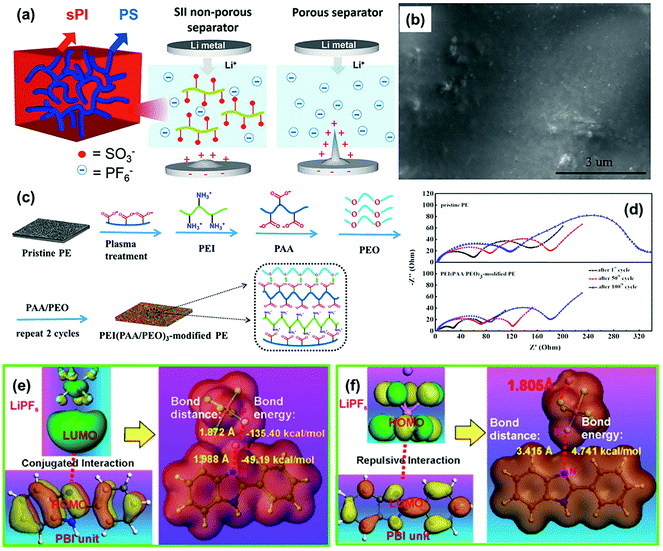 | ||
| Fig. 12 (a) Schematic illustration of the microstructure of the SII separator and the proposed electrochemical deposition behavior of lithium ions in the lithium symmetrical cell comprised of SII–LE (the electrolyte filled SII separator) and Celgard–LE (Celgard 2320 saturated with LE). (b) SEM images of lithium metal surface of the Li/separator–LE/Li cells comprised of SII-LE after 245 h of galvanostatic cycling. Reproduced with permission from ref. 106. Copyright 2019, Elsevier. (c) Layer-by-Layer process of the PEI(PAA/PEO)3-modified PE separator. (d) Variation in the AC impedance spectra (1st cycle–50th cycle–100th cycle) of the cells assembled with pristine PE and the PEI(PAA/PEO)3-modified PE separator. Reproduced with permission from ref. 107. Copyright 2018, American Chemical Society. (e) The calculated electrostatic potential of LiPF6, PBI unit, and PBI unit/LiPF6 to illustrate the conjugated interaction between Li+ and the electron-rich imidazole ring. (f) The repulsive interaction between PF6− and the electron-rich imidazole ring. Reproduced with permission from ref. 108. Copyright 2019, Nature. | ||
For achieving high Li+ selectivity, MOFs are also considered as one of the most promising materials for constructing functional separator used in LMBs. On the one hand, some MOFs contain plenty of opened metal sites (OMS) that could immobilize anions in the electrolyte.115 For instance, Zhang and co-workers reported the realization of Li+ selectivity by fibrous composite separators (EMP) embedded with MOF particles as anion sorbent.68 The anions in the electrolytes could be spontaneously adsorbed by the MOF particles and immobilized within its nanochannels (Fig. 13a). As a result, the tLi+ of the EMP separator was much higher than that of the commercial PP separator in different electrolyte solvents and the optimized tLi+ reached up to 0.79 (Fig. 13b). The lithium dendrites could be effectively suppressed when integrating this functional separator into the LMBs. On the other hand, MOFs are ideal ion-sieve materials because of their high-density nano-confined pores, which could serve as ion sieves for the selective transport of Li+. To elucidate the transport behaviors of the electrolyte ions in the pores of MOFs, Zhou's group comprehensively calculated and analysed the transport of Li+ and TFSI− anions in the MOF-modified electrolyte (Fig. 13c).116 They found that the MOF skeletons with well-ordered angstrom-scale pores could essentially impose a spatial restriction on the TFSI− anion migration. The TFSI− anions could be caged in the nanochannels of MOF and Li+ could present high mobility to result in a homogeneous Li+ flux, which significantly inhibited the formation of lithium dendrites. Furthermore, the separator regulating ionic transport could be greatly promoted by the simultaneous realization of size sieving and anion immobilization. Recently, Liu et al. proposed a strategy to construct high-performance separators by coating amino-functionalized titanium-based MOF (NH2-MIL-125(Ti)) onto commercial Celgard PP separators.109 The interactions between the −NH2 groups and Li+ could deliver a much higher tLi+ (0.78) of the separator when used in Li–Li cells. Compared with the pristine Celgard separator, the modification of NH2-MIL-125(Ti) contributed to a much longer cycling lifetime over 1200 h in the cell under different current densities (Fig. 13d). However, the interactions of the functional separator with the ions responsible for outstanding cycle stability has not been explained in detail in this work. Similarly, Xie et al. applied covalent organic frameworks (COFs) as the functional coating of the PP separator to eliminate lithium dendrites.110 The COFs also had abundant ordered sub-nanopores that could hinder the movement of anions and allow the transport of Li+. In their work, the routine separator functionalized by COFs delivered a high tLi+ of ∼0.77. The above studies presented outstanding performance and promising prospect of MOF and COF materials for stable lithium metal anodes, which are of significance in material selection and structure design of high-performance functional separators.
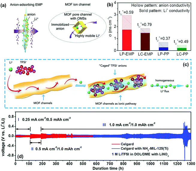 | ||
| Fig. 13 (a) Schematics showing a functional EMP for adsorbing anions and facilitating the transport of lithium ions. (b) Comparisons on tLi+ and separated ion conductivity. Reproduced with permission from ref. 68. Copyright 2019, Wiley. (c) Schematic of the selective Li+ ionic transport imposed by the MOF host. Reproduced with permission from ref. 116. Copyright 2018, Elsevier. (d) Voltage profiles of Li metal plating/striping in symmetric Li|Li cells with pristine and NH2-MIL-125(Ti)-coated separators. Reproduced with permission from ref. 109. Copyright 2017, The Royal Society of Chemistry. | ||
Numerous theoretical and experimental studies have proved that charged nanochannels, whose pore radius was close to double layer thickness, could selectively transport counter-ions (opposite charge) while prevent the co-ions (same charge). This principle provides the basis for designing and fabricating functional separators with excellent Li+ selectivity. Vary recently, Yang and co-workers developed a novel nanochannel separator based on perpendicular nanochannels (mesoporous silica thin films with a pore size of ∼5 nm) stacked on the AAO membrane (MSTF⊥AAO), which presented the ultra-long term stability of Li plating/stripping in LMB.111 As illustrated in Fig. 14a and b, the negatively charged nanochannels could not only selectively transport Li+ but also promote homogeneous Li plating. In contrast, the non-selective AAO separator with much larger nanopores (70 nm) would cause non-uniform lithium deposition and thus the dendrite formation. When compared with the AAO separator, the MSTF⊥AAO separator delivered a much longer cycling life for over 400 h even at an extremely high current density of 20 mA cm−2 and a capacity of 10 mA h cm−2 (Fig. 14c). The rational design of nanochannel separators with ionic transport regulation property has shown their tremendous potential in long lifetime LMBs.
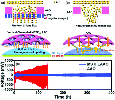 | ||
Fig. 14 A schematic figure of Li deposition on the electrode through (a) the MSTF⊥AAO separator and (b) the AAO separator. (c) The galvanostatic cycling performance of the Li–Li symmetric cells with the bare AAO (red line) and MSTF⊥AAO (blue line) at fixed current densities of 20 mA cm−2 and capacity of 10 mA h cm−2. The electrolyte is 1 M LiTFSI in a 1![[thin space (1/6-em)]](https://www.rsc.org/images/entities/char_2009.gif) : :![[thin space (1/6-em)]](https://www.rsc.org/images/entities/char_2009.gif) 1 (v/v) solution of DOL/DME. Reproduced with permission from ref. 111. Copyright 2020, The Royal Society of Chemistry. 1 (v/v) solution of DOL/DME. Reproduced with permission from ref. 111. Copyright 2020, The Royal Society of Chemistry. | ||
As discussed above, functional separators having Li+ selectivity could suppress the nucleation process of lithium dendrites, which is more promising for obtaining dendrite-free lithium metal anode compared with the other two strategies. However, developing a cation-selective separator usually requires elaborate material selection and structure design, which is challenging for their high-quality preparation and scale production. The mechanisms responsible for the functional separator regulating ionic transport are still not very clear yet, which need to studied in detail in further studies. Besides, it is worth mentioning that the above three typical strategies for separator functionalization are not isolated. A well-designed separator could simultaneously possess two or even three of the functions mentioned above. For example, nanoporous AAO separators not only have high mechanical strength but also provide uniform pores for homogeneous Li deposition. In addition, functional separators based on AAO and MOFs could be endowed with cation-selective property after the modification with negatively charged moieties. Thus, it is anticipated to construct high-performance multifunctional separators towards advanced dendrite-free LMBs.
5.4. Others
Except for suppressing the formation and growth of lithium dendrites, some intelligent functions have been endowed to the separators for addressing the security issues caused by lithium dendrites. As discussed above, it is difficult to prevent the internal short-circuit in LMBs by routine separators because they usually do not work to block the overgrowth of long dendrites (Fig. 15a). Concerning this problem, Cui's group recently constructed a smart separator for the early detection of internal short-circuit in LMB.117 Owing to a sandwiched polymer–metal–polymer triple layer configuration, the separator demonstrated an additional voltage-sensing behavior except for electronic insulation such as routine separators. As illustrated in Fig. 15b, the voltage between the intermediary metal layer of the separator and the lithium metal anode could be monitored in real-time. When a lithium dendrite reaches the metal layer in the separator, an obvious voltage drop appears immediately to warn about the battery safety. Thus, some serious security issues of the LMB such as fire and explosion could be effectively prevented by the smart separator. Subsequently, they constructed a similar trilayer separator based on a silica nanoparticle layer sandwiched between two PE separators in order to suppress lithium dendrites for extending the life of the LMBs.118 As shown in Fig. 15c, the sandwiched middle layer of the silica nanoparticles could react with the lithium dendrites penetrating into the separator, thus slowing down the further growth of lithium dendrites, which contributed to a much longer lifetime of the battery compared with that of routine separators (Fig. 15d). Similarly, the TiO2 nanoparticle coating was also used as a Li-killing layer to prevent dendrite penetration in the separator via a chemical reaction.119 To enable the next-generation LMBs, Liu's group designed a novel Janus separator to mitigate the impact of internal short-circuit.120 The Janus separator had a double layer structure composed of an electronically insulated section and a partially electronically conductive (PEC) one with tunable conductivity (Fig. 15e). The separator could intercept the oncoming dendrite and significantly enhance the short-circuit resistance (Rshort). The additional resistance offered by the PEC side (RPEC) will cut off the circuit once the lithium dendrites penetrated the electronically insulating side (Fig. 15f).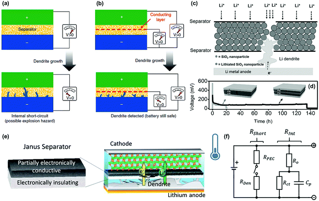 | ||
| Fig. 15 (a) Dendrite formation in a traditional lithium battery where the complete penetration of the separator by a lithium dendrite is only detected when the battery fails due to an internal short-circuit and VLi–Li drops to zero. (b) In comparison, a lithium battery with a bifunctional separator (consisting of a conducting layer sandwiched between two conventional separators) where the overgrown lithium dendrite penetrates into the separator and makes contact with the conducting copper layer, giving rise to a drop in VCu–Li as a warning of impending failure due to an internal short-circuit. However, the full battery remains safely operational with non-zero potential. Reproduced with permission from ref. 117. Copyright 2014, Nature. (c) Schematic showing the mechanism for extended battery life using silica nanoparticle sandwiched separator. (d) Typical voltage versus time profile of an Li/Li battery with a conventional separator (grey curve) and the silica nanoparticle-sandwiched trilayer separator (black curve) tested under the same conditions. To accelerate the formation and growth of dendrites within reasonable time frames, a pinhole with a diameter of 50 μm was punched through both of the separators before being assembled into the battery. Reproduced with permission from ref. 118. Copyright 2016, Wiley. (e) Schematic of the Janus separator implemented in a lithium battery. The black side is PEC and the white side is electronically insulating. The Janus separator limits the rate of self-discharge by intercepting the dendrite and increasing the short-circuit resistance. (f) The Thévenin equivalent circuit of the cell containing a Janus separator during internal shorting with the additional resistance, RPEC, from the Janus separator. Reproduced with permission from ref. 120. Copyright 2020, Wiley. | ||
The regulation of the SEI film by the functional separator has proved to be a feasible approach to inhibit the lithium dendrites. In LMBs, the charging process makes the lithium metal anode suffer from massive volume expansion owing to its hostless nature, which causes SEI film fracture and thus facilitates the formation of lithium dendrites.121–123 Based on this principle, Boateng et al. proposed a new strategy to construct a resilient SEI film by modifying the routine separator with organosulfur compounds and inorganic salts derived from garlic.123 In LMBs, the organosulfur compounds played key roles in electrolyte chemistry to generate a stable and resilient SEI film that could accommodate deformations during the Li plating process (Fig. 16a). Similarly, an advanced separator was developed to stabilize the SEI film based on the aramid paper attached with reduced graphene oxide fiber (rGOF-A).124 In this functional separator, the rGOF acted as a framework for stable SEI and thus prevented the growth of lithium dendrites. Moreover, the surface of the rGOF could become an “F-doped” state after reacting with the LiPF6 electrolyte, which contributed to the formation of a SEI layer containing stable LiF in a high proportion. Even in harsh conditions (20 mA h cm−2, 20 mA h cm−2), the Li–Li cell with this separator could maintain stability for long-term cycling (Fig. 16b). Recently, Yan et al. coated MnCO3 functional layer on the PP separator to achieve dendrite-free lithium deposition.125 On the one hand, Mn2+ could be reduced to Mn nanoparticles near the lithium metal at reasonably low potentials, which decreased the nucleation overpotential of lithium deposition and thus promoted dendrite-free lithium deposition. On the other hand, the direct contact between the MnCO3 coating and the Li foil helped to form an artificial SEI layer composed of Li2CO3/Mn/MnCO3 and organic components, which was beneficial for the improvement of the Li plating/stripping efficiency. The above studies provided new insights for creating a steady SEI layer on the lithium metal anode for suppressing dendrite growth in advanced LMBs.
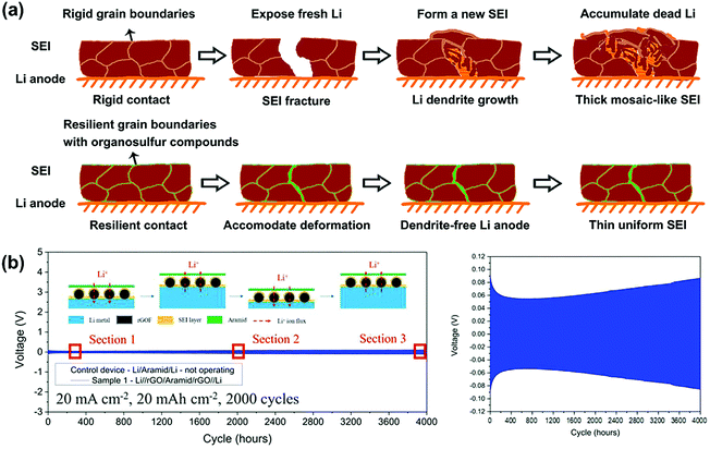 | ||
| Fig. 16 (a) Schematics of SEI evolution and dendrite formation on the Li anode with and without organosulfur compounds. Reproduced with permission from ref. 123. Copyright 2020 American Chemical Society. (b) Galvanostatic cycling measurement of the symmetrical cell test under harsh conditions (20 mA cm−2, 20 mA h cm−2). Reproduced with permission from ref. 124. Copyright 2020 Wiley. | ||
6. Conclusion and outlook
With the development of LMBs, addressing the issues of lithium dendrites through separator functionalization strategies have aroused increasing attentions and many great advances have been made in recent years. In spite of this, there is still a long way to go for developing advanced characterization techniques and constructing high-performance functional separators in order to meet the challenges in advanced LMBs. More importantly, it is desired to promote the scale production of functional separators for reaching the practical applications of high-energy LMBs.6.1. Developing advanced characterization techniques
Advanced characterization techniques are of great importance for studying the behavior of the formation and growth of lithium dendrites in LMBs. On the one hand, detecting the deposition behavior of lithium dendrites in more visual ways by using some advanced characterization techniques will help in further understanding its mechanism, which could provide the direction for effectively suppressing lithium dendrites. On the other hand, simulation and calculation have developed rapidly in recent years, which may be critical areas for further studies on LMBs. It can be predicted that more efforts devoted to this related field will be reported in the near future.6.2. Constructing high-performance functional separators
The nucleation and growth of lithium dendrites are highly related to the transport properties of Li+ as well as anions. Therefore, functional separators that regulating ionic transport have proved to be more effective for suppressing lithium dendrites, especially for the high-current operation of LMBs. However, current research on functional separators regulating ionic transport is still at an early stage. Although there has been a significant improvement in the battery performance, the mechanism that is responsible for ionic transport behaviors boosted by functional separators is not very clear. Furthermore, some separators could simultaneously possess more than one function. For instance, separators with ordered nanochannels could achieve homogeneous lithium deposition, which also demonstrates excellent Li+ selectivity after functionalizing with negatively charged moieties.126 Multifunctional separators are considered as the most potential candidates for creating dendrite-free LMBs, which calls for more attention in further studies. Except for pursuing multiple functions within a separator, constructing smart separators is another developing trend for addressing the security issues in LMBs because they can achieve the monitoring of lithium dendrite growth behaviors.117,127 Therefore, more attention should be given to the construction of functional separators for boosting high-performance LMBs.6.3. Promoting the practical applications of functional separators
Although functional separators exhibit superior performance in suppressing lithium dendrites compared with the conventional ones, there are still large challenges in pushing them into practical applications. On the one hand, most functional separators require expensive materials and complex preparation processes, which seriously limit their large-scale production. On the other hand, the physical and chemical stability of the functional separators remains to be considered when applied in actual operating conditions. Thirdly, some new technologies are required to be developed for battery assembly based on functional separators. In spite of this, it is foreseeable that functional separators are promising components in advanced LMBs.As summarized in this paper, the latest advances and progresses of separator functionalization for the suppression of lithium dendrites were reviewed in detail. On the basis of reasonable functional design, the separator could be endowed with desirable features such as providing a mechanical barrier, promoting homogeneous lithium deposition, and regulating ionic transport, which have significant effects in inhibiting the dendritic growth or even nucleation. Some challenges and prospects were proposed in the construction of high-performance functional separators and their practical applications. It is envisioned that this work will create new avenues for constructing advanced dendrite-free LMBs.
Conflicts of interest
There are no conflicts to declare.Acknowledgements
This work was supported by Natural Science Foundation of Beijing Municipality (L182008), Beijing Nova Program (Z201100006820112), and National Natural Science Foundation of China (21701003).References
- D. Lin, Y. Liu and Y. Cui, Nat. Nanotechnol., 2017, 12, 194–206 CrossRef CAS.
- Y. Fu, Y. Wan, H. Xia and X. Wang, J. Power Sources, 2012, 213, 338–342 CrossRef CAS.
- T. Ohzuku and R. J. Brodd, J. Power Sources, 2007, 174, 449–456 CrossRef CAS.
- Z. Hao, X. Xu, H. Wang, J. Liu and H. Yan, Ionics, 2018, 24, 951–965 CrossRef CAS.
- Z. Hao, X. Xu, H. Wang, J. Liu and H. Yan, NANO, 2018, 13, 1830007 CrossRef.
- J. Janek and W. G. Zeier, Nat. Energy, 2016, 1, 16141 CrossRef.
- L. Ma, J. Cui, S. Yao, X. Liu, Y. Luo, X. Shen and J. Kim, Energy Storage Mater., 2020, 27, 522–554 CrossRef.
- K. Zhang, G. H. Lee, M. Park, W. Li and Y. M. Kang, Adv. Energy Mater., 2016, 6, 1600811 CrossRef.
- X. Q. Zhang, X. Chen, R. Xu, X. B. Cheng, H. J. Peng, R. Zhang, J. Q. Huang and Q. Zhang, Angew. Chem., Int. Ed., 2017, 56, 14207–14211 CrossRef CAS.
- C. Zu and A. Manthiram, J. Phys. Chem. Lett., 2014, 5, 2522–2527 CrossRef CAS.
- H. J. Peng, J. Q. Huang, X. B. Cheng and Q. Zhang, Adv. Energy Mater., 2017, 7, 1700260 CrossRef.
- A. Manthiram, S. H. Chung and C. Zu, Adv. Mater., 2015, 27, 1980–2006 CrossRef CAS.
- P. G. Bruce, S. A. Freunberger, L. J. Hardwick and J. Tarascon, Nat. Mater., 2012, 11, 19–29 CrossRef CAS.
- V. A. Agubra, L. Zuniga, D. Flores, J. Villareal and M. Alcoutlabi, Electrochim. Acta, 2016, 192, 529–550 CrossRef CAS.
- Z. Song, Y. Qian, X. Liu, T. Zhang, Y. Zhu, H. Yu, M. Otani and H. Zhou, Energy Environ. Sci., 2014, 7, 4077–4086 RSC.
- T. Hibino, K. Kobayashi and M. Nagao, J. Mater. Chem. A, 2013, 1, 14844–14848 RSC.
- X. Xu, S. Wang, H. Wang, C. Hu, Y. Jin, J. Liu and H. Yan, J. Energy Chem., 2018, 27, 513–527 CrossRef.
- Q. Lu, Y. B. He, Q. Yu, B. Li, Y. V. Kaneti, Y. Yao, F. Kang and Q. H. Yang, Adv. Mater., 2017, 29, 1604460 CrossRef.
- H. Yang, C. Guo, A. Naveed, J. Lei, J. Yang, Y. Nuli and J. Wang, Energy Storage Mater., 2018, 14, 199–221 CrossRef.
- X. B. Cheng, H. J. Peng, J. Q. Huang, F. Wei and Q. Zhang, Small, 2014, 10, 4257–4263 CAS.
- S. Liu, X. Xia, Y. Zhong, S. Deng, Z. Yao, L. Zhang, X. B. Cheng, X. Wang, Q. Zhang and J. Tu, Adv. Energy Mater., 2018, 8, 1702322 CrossRef.
- J. Kim, D. W. Kim, H. T. Jung and J. W. Choi, Chem. Mater., 2015, 27, 2780–2787 CrossRef CAS.
- L. Wang, Q. Wang, W. Jia, S. Chen, P. Gao and J. Li, J. Power Sources, 2017, 342, 175–182 CrossRef CAS.
- J. K. Kim, D. H. Kim, S. H. Joo, B. Choi, A. Cha, K. M. Kim, T. H. Kwon, S. K. Kwak, S. J. Kang and J. Jin, ACS Nano, 2017, 11, 6114–6121 CrossRef CAS.
- J. Wu, H. Zeng, X. Li, X. Xiang, Y. Liao, Z. Xue, Y. Ye and X. Xie, Adv. Energy Mater., 2018, 8, 1802430 CrossRef.
- H. Zhang, G. G. Eshetu, X. Judez, C. Li, L. M. Rodriguez-Martínez and M. Armand, Angew. Chem., Int. Ed., 2018, 57, 15002–15027 CrossRef CAS.
- Y. Liu, D. Lin, Y. Li, G. Chen, A. Pei, O. Nix, Y. Li and Y. Cui, Nat. Commun., 2018, 9, 1–10 CrossRef.
- J. Zhu, P. Li, X. Chen, D. Legut, Y. Fan, R. Zhang, Y. Lu, X. Cheng and Q. Zhang, Energy Storage Mater., 2019, 16, 426–433 CrossRef.
- L. Fan, Z. Guo, Y. Zhang, X. Wu, C. Zhao, X. Sun, G. Yang, Y. Feng and N. Zhang, J. Mater. Chem. A, 2020, 8, 251–258 RSC.
- C. P. Yang, Y. X. Yin, S. F. Zhang, N. W. Li and Y. G. Guo, Nat. Commun., 2015, 6, 8058 CrossRef CAS.
- Y. An, H. Fei, G. Zeng, X. Xu, L. Ci, B. Xi, S. Xiong, J. Feng and Y. Qian, Nano Energy, 2018, 47, 503–511 CrossRef CAS.
- Z. Hao, C. Wu, Q. Zhang, J. Liu and H. Wang, Int. J. Energy Res., 2019, 43, 8049–8056 CrossRef CAS.
- H. Lee, M. Yanilmaz, O. Toprakci, K. Fu and X. Zhang, Energy Environ. Sci., 2014, 7, 3857–3886 RSC.
- V. Deimede and C. Elmasides, Energy Technol., 2015, 3, 453–468 CrossRef.
- Y. He, Y. Qiao, Z. Chang and H. Zhou, Energy Environ. Sci., 2019, 12, 2327–2344 RSC.
- L. Shen, H. B. Wu, F. Liu, C. Zhang, S. Ma, Z. Le and Y. Lu, Nanoscale Horiz., 2019, 4, 705–711 RSC.
- J. Luo, Y. Li, H. Zhang, A. Wang, W. S. Lo, Q. Dong, N. Wong, C. Povinelli, Y. Shao, S. Chereddy, S. Wunder, U. Mohanty, C. K. Tsung and D. Wang, Angew. Chem., Int. Ed., 2019, 58, 15313–15317 CrossRef CAS.
- S. Chun, E. Choi, E. Lee, J. H. Kim, S. Lee and S. Lee, J. Mater. Chem., 2012, 22, 16618–16626 RSC.
- S. S. Zhang, J. Power Sources, 2007, 164, 351–364 CrossRef CAS.
- H. J. S. Sand, Philos. Mag., 1901, 1, 45–79 CAS.
- P. Bai, J. Li, F. R. Brushett and M. Z. Bazant, Energy Environ. Sci., 2016, 9, 3221–3229 RSC.
- F. Wu, Y. X. Yuan, X. B. Cheng, Y. Bai, Y. Li, C. Wu and Q. Zhang, Energy Storage Mater., 2018, 15, 148–170 CrossRef.
- J. Yamaki, S. Tobishima, K. Hayashi, K. Saito, Y. Nemoto and M. Arakawa, J. Power Sources, 1998, 74, 219–227 CrossRef CAS.
- E. Peled, J. Electrochem. Soc., 1979, 126, 2047 CrossRef CAS.
- G. Zheng, S. W. Lee, Z. Liang, H. W. Lee, K. Yan, H. Yao, H. Wang, W. Li, S. Chu and Y. Cui, Nat. Nanotechnol., 2014, 9, 618–623 CrossRef CAS.
- X. B. Cheng and Q. Zhang, J. Mater. Chem. A, 2015, 3, 7207–7209 RSC.
- F. Ding, W. Xu, G. L. Graff, J. Zhang, M. L. Sushko, X. Chen, Y. Shao, M. H. Engelhard, Z. Nie and J. Xiao, J. Am. Chem. Soc., 2013, 135, 4450–4456 CrossRef CAS.
- Y. Okajima, Y. Shibuta and T. Suzuki, Comput. Mater. Sci., 2010, 50, 118–124 CrossRef CAS.
- D. Wang, W. Zhang, W. Zheng, X. Cui, T. Rojo and Q. Zhang, Adv. Sci., 2017, 4, 1600168 CrossRef.
- X. B. Cheng, R. Zhang, C. Z. Zhao and Q. Zhang, Chem. Rev., 2017, 117, 10403–10473 CrossRef CAS.
- C. Zhao, Y. Lu, J. Yue, D. Pan, Y. Qi, Y. Hu and L. Chen, J. Energy Chem., 2018, 27, 1584–1596 CrossRef.
- Y. Li, Y. Li, A. Pei, K. Yan, Y. Sun, C. L. Wu, L. M. Joubert, R. Chin, A. L. Koh, Y. Yu, J. Perrino, B. Butz, S. Chu and Y. Cui, Science, 2017, 358, 506–510 CrossRef CAS.
- K. J. Harry, D. T. Hallinan, D. Y. Parkinson, A. A. MacDowell and N. P. Balsara, Nat. Mater., 2014, 13, 69–73 CrossRef CAS.
- X. Xu, H. Wang, Y. Xie, J. Liu, H. Yan and W. Liu, J. Electrochem. Soc., 2018, 165, A2978–A2984 CrossRef CAS.
- G. Rong, X. Zhang, W. Zhao, Y. Qiu, M. Liu, F. Ye, Y. Xu, J. Chen, Y. Hou, W. Li, W. Duan and Y. Zhang, Adv. Mater., 2017, 29, 1606187 CrossRef.
- Z. Zeng, W. I. Liang, H. G. Liao, H. L. Xin, Y. H. Chu and H. Zheng, Nano Lett., 2014, 14, 1745–1750 CrossRef CAS.
- E. de Smit, I. Swart, J. F. Creemer, G. H. Hoveling, M. K. Gilles, T. Tyliszczak, P. J. Kooyman, H. W. Zandbergen, C. Morin, B. M. Weckhuysen and F. M. F. de Groot, Nature, 2008, 456, 222–225 CrossRef CAS.
- J. Nelson, S. Misra, Y. Yang, A. Jackson, Y. Liu, H. Wang, H. Dai, J. C. Andrews, Y. Cui and M. F. Toney, J. Am. Chem. Soc., 2012, 134, 6337–6343 CrossRef CAS.
- Z. Deng, X. Lin, Z. Huang, J. Meng, Y. Zhong, G. Ma, Y. Zhou, Y. Shen, H. Ding and Y. Huang, Adv. Energy Mater., 2020, 2000806 CrossRef.
- S. H. Yu, X. Huang, J. D. Brock and H. D. Abruna, J. Am. Chem. Soc., 2019, 141, 8441–8449 CrossRef CAS.
- H. J. Chang, A. J. Ilott, N. M. Trease, M. Mohammadi, A. Jerschow and C. P. Grey, J. Am. Chem. Soc., 2015, 137, 15209–15216 CrossRef CAS.
- P. Arora and Z. Zhang, Chem. Rev., 2004, 104, 4419–4462 CrossRef CAS.
- S. Suriyakumar and A. M. Stephan, ACS Appl. Energy Mater., 2020, 3, 8095–8129 CrossRef CAS.
- S. Suriyakumar, A. M. Stephan, N. Angulakshmi, M. H. Hassan and M. H. Alkordi, J. Mater. Chem. A, 2018, 6, 14623–14632 RSC.
- S. Suriyakumar, M. Kanagaraj, M. Kathiresan, N. Angulakshmi, S. Thomas and A. M. Stephan, Electrochim. Acta, 2018, 265, 151–159 CrossRef CAS.
- J. Q. Huang, Q. Zhang, H. J. Peng, X. Y. Liu, W. Z. Qian and F. Wei, Energy Environ. Sci., 2014, 7, 347–353 RSC.
- H. Yao, K. Yan, W. Li, G. Zheng, D. Kong, Z. W. Seh, V. K. Narasimhan, Z. Liang and Y. Cui, Energy Environ. Sci., 2014, 7, 3381–3390 RSC.
- C. Zhang, L. Shen, J. Shen, F. Liu, G. Chen, R. Tao, S. Ma, Y. Peng and Y. Lu, Adv. Mater., 2019, 31, 1808338 CrossRef.
- W. K. Shin, A. G. Kannan and D. W. Kim, ACS Appl. Mater. Interfaces, 2015, 7, 23700–23707 CrossRef CAS.
- W. Na, A. S. Lee, J. H. Lee, S. S. Hwang, E. Kim, S. M. Hong and C. M. Koo, ACS Appl. Mater. Interfaces, 2016, 8, 12852–12858 CrossRef CAS.
- M. Rosso, C. Brissot, A. Teyssot, M. Dollé, L. Sannier, J. Tarascon, R. Bouchet and S. Lascaud, Electrochim. Acta, 2006, 51, 5334–5340 CrossRef CAS.
- D. A. Dornbusch, R. Hilton, S. D. Lohman and G. J. Suppes, J. Electrochem. Soc., 2014, 162, A262–A268 CrossRef.
- A. Jana, D. R. Ely and R. E. García, J. Power Sources, 2015, 275, 912–921 CrossRef CAS.
- Z. Zhang, Y. Lai, Z. Zhang, K. Zhang and J. Li, Electrochim. Acta, 2014, 129, 55–61 CrossRef CAS.
- H. Jeon, S. Y. Jin, W. H. Park, H. Lee, H. Kim, M. Ryou and Y. M. Lee, Electrochim. Acta, 2016, 212, 649–656 CrossRef CAS.
- F. Zhu, J. Liu, H. Zhao, J. Li, Q. Li, Y. Xi, M. Liu and C. Wang, ChemElectroChem, 2019, 6, 2883–2890 CrossRef CAS.
- J. Y. Hwang, H. M. Kim, S. Shin and Y. K. Sun, Adv. Funct. Mater., 2018, 28, 1704294 CrossRef.
- J. Liang, Q. Chen, X. Liao, P. Yao, B. Zhu, G. Lv, X. Wang, X. Chen and J. Zhu, Angew. Chem., Int. Ed., 2020, 59, 6561–6566 CrossRef CAS.
- H. Qu, J. Ju, B. Chen, N. Xue, H. Du, X. Han, J. Zhang, G. Xu, Z. Yu, X. Wang and G. Cui, J. Mater. Chem. A, 2018, 6, 23720–23729 RSC.
- K. Liu, P. Bai, M. Z. Bazant, C. Wang and J. Li, J. Mater. Chem. A, 2017, 5, 4300–4307 RSC.
- J. Liu, Y. Mo, S. Wang, S. Ren, D. Han, M. Xiao, L. Sun and Y. Meng, ACS Appl. Energy Mater., 2019, 2, 3886–3895 CrossRef CAS.
- W. Wang, C. Liao, K. M. Liew, Z. Chen, L. Song, Y. Kan and Y. Hu, J. Mater. Chem. A, 2019, 7, 6859–6868 RSC.
- R. Pan, X. Xu, R. Sun, Z. Wang, J. Lindh, K. Edström, M. Strømme and L. Nyholm, Small, 2018, 14, 1704371 CrossRef.
- Z. Wang, R. Pan, C. Xu, C. Ruan, K. Edström, M. Strømme and L. Nyholm, Energy Storage Mater., 2018, 13, 283–292 CrossRef.
- S. J. Kang, T. Mori, J. Suk, D. W. Kim, Y. Kang, W. Wilcke and H. Kim, J. Mater. Chem. A, 2014, 2, 9970–9974 RSC.
- W. Wang, F. Hao and P. P. Mukherjee, ACS Appl. Mater. Interfaces, 2020, 12, 556–566 CrossRef CAS.
- Y. He, Z. Chang, S. Wu, Y. Qiao, S. Bai, K. Jiang, P. He and H. Zhou, Adv. Energy Mater., 2018, 8, 1802130 CrossRef.
- Z. Rao, Z. Yang, W. Gong, S. Su, Q. Fu and Y. Huang, J. Mater. Chem. A, 2020, 8, 3859–3864 RSC.
- R. Pan, R. Sun, Z. Wang, J. Lindh, K. Edström, M. Strømme and L. Nyholm, Nano Energy, 2019, 55, 316–326 CrossRef CAS.
- H. Zhao, N. Deng, W. Kang, Z. Li, G. Wang and B. Cheng, Energy Storage Mater., 2020, 26, 334–348 CrossRef.
- J. Zhao, D. Chen, B. Boateng, G. Zeng, Y. Han, C. Zhen, J. B. Goodenough and W. He, J. Power Sources, 2020, 451, 227773 CrossRef CAS.
- Y. Ahn, J. Park, D. Shin, S. Cho, S. Y. Y. Park, H. Kim, Y. Piao, J. Yoo and Y. S. Kim, J. Mater. Chem. A, 2015, 3, 10715–10719 RSC.
- Q. Zhang, Z. Liu, K. Wang and J. Zhai, Adv. Funct. Mater., 2015, 25, 2091–2098 CrossRef CAS.
- Q. Zhang, Z. Hu, Z. Liu, J. Zhai and L. Jiang, Adv. Funct. Mater., 2014, 24, 424–431 CrossRef CAS.
- Q. Zhang, Q. Liu, J. Kang, Q. Huang, Z. Liu, X. Diao and J. Zhai, Adv. Sci., 2018, 5, 1800163 CrossRef.
- H. B. Wu, S. Wei, L. Zhang, R. Xu, H. H. Hng and X. W. Lou, Chem. – Eur. J., 2013, 19, 10804–10808 CrossRef CAS.
- R. Li, J. Jiang, Q. Liu, Z. Xie and J. Zhai, Nano Energy, 2018, 53, 643–649 CrossRef CAS.
- Z. Hao, X. Xu, S. Deng, H. Wang, J. Liu and H. Yan, Ionics, 2019, 25, 2469–2476 CrossRef CAS.
- M. Ryou, D. J. Lee, J. Lee, Y. M. Lee, J. Park and J. W. Choi, Adv. Energy Mater., 2012, 2, 645–650 CrossRef CAS.
- J. K. Kim, D. H. Kim, S. H. Joo, B. Choi, A. Cha, K. M. Kim, T. Kwon, S. K. Kwak, S. J. Kang and J. Jin, ACS Nano, 2017, 11, 6114–6121 CrossRef CAS.
- L. Ma, R. Chen, Y. Hu, W. Zhang, G. Zhu, P. Zhao, T. Chen, C. Wang, W. Yan, Y. Wang, L. Wang, Z. Tie, J. Liu and Z. Jin, Energy Storage Mater., 2018, 14, 258–266 CrossRef.
- C. Li, S. Liu, C. Shi, G. Liang, Z. Lu, R. Fu and D. Wu, Nat. Commun., 2019, 10, 1363 CrossRef.
- D. R. Sadoway, B. Huang, P. E. Trapa, P. P. Soo, P. Bannerjee and A. M. Mayes, J. Power Sources, 2001, 97, 621–623 CrossRef.
- D. H. Jeon and S. M. Baek, Energy Convers. Manage., 2011, 52, 2973–2981 CrossRef CAS.
- Y. Tada, M. Sato, N. Takeno, Y. Nakacho and K. Shigehara, Chem. Mater., 1994, 6, 27–30 CrossRef CAS.
- K. Liu, C. Chao, H. Lee, C. Tsao, J. Fang, N. Wu and C. Chao, J. Power Sources, 2019, 419, 58–64 CrossRef CAS.
- R. Jin, L. Fu, H. Zhou, Z. Wang, Z. Qiu, L. Shi, J. Zhu and S. Yuan, ACS Sustainable Chem. Eng., 2018, 6, 2961–2968 CrossRef CAS.
- J. Wang, Y. He, Q. Wu, Y. Zhang, Z. Li, Z. Liu, S. Huo, J. Dong, D. Zeng and H. Cheng, Sci. Rep., 2019, 9, 1–10 CrossRef.
- W. Liu, Y. Mi, Z. Weng, Y. Zhong, Z. Wu and H. Wang, Chem. Sci., 2017, 8, 4285–4291 RSC.
- H. Xie, Q. Hao, H. Jin, S. Xie, Z. Sun, Y. Ye, C. Zhang, D. Wang, H. Ji and L. J. Wan, Sci. China: Chem., 2020, 63, 1306–1314 CrossRef CAS.
- J. Yang, C. Wang, C. Wang, K. Chen, C. Mou and H. Wu, J. Mater. Chem. A, 2020, 8, 5095–5104 RSC.
- M. Chen, Z. Chen, X. Fu and W. H. Zhong, J. Mater. Chem. A, 2020, 8, 7377–7389 RSC.
- Y. Yan, Q. R. Kong, C. C. Sun, J. J. Yuan, Z. Huang, L. F. Fang, B. K. Zhu and Y. Z. Song, Chin. J. Polym. Sci., 2020 DOI:10.1007/s10118-020-2455-1.
- Y. Yang, W. Wang, L. Li, B. Li and J. Zhang, J. Mater. Chem. A, 2020, 8, 3692–3700 RSC.
- T. Kajiwara, M. Higuchi, D. Watanabe, H. Higashimura, T. Yamada and H. Kitagawa, Chem. – Eur. J., 2014, 20, 15611–15617 CrossRef CAS.
- S. Bai, Y. Sun, J. Yi, Y. He, Y. Qiao and H. Zhou, Joule, 2018, 2, 2117–2132 CrossRef CAS.
- H. Wu, D. Zhuo, D. Kong and Y. Cui, Nat. Commun., 2014, 5, 5193 CrossRef CAS.
- K. Liu, D. Zhuo, H. Lee, W. Liu, D. Lin, Y. Lu and Y. Cui, Adv. Mater., 2017, 29, 1603987 CrossRef.
- S. S. Zhang, X. Fan and C. Wang, J. Mater. Chem. A, 2018, 6, 10755–10760 RSC.
- M. S. Gonzalez, Q. Yan, J. Holoubek, Z. Wu, H. Zhou, N. Patterson, V. Petrova, H. Liu and P. Liu, Adv. Mater., 2020, 32, 1906836 CrossRef CAS.
- X. B. Cheng, C. Yan, H. J. Peng, J. Q. Huang, S. T. Yang and Q. Zhang, Energy Storage Mater., 2018, 10, 199–205 CrossRef.
- X. B. Cheng, C. Yan, X. Chen, C. Guan, J. Q. Huang, H. J. Peng, R. Zhang, S. T. Yang and Q. Zhang, Chem, 2017, 2, 258–270 CAS.
- B. Boateng, Y. Han, C. Zhen, G. Zeng, N. Chen, D. Chen, C. Feng, J. Han, J. Xiong, X. Duan and W. He, Nano Lett., 2020, 20, 2594–2601 CrossRef CAS.
- Y. J. Gong, J. W. Heo, H. Lee, H. Kim, J. Cho, S. Pyo, H. Yun, H. Kim, S. Y. Park, J. Yoo and Y. S. Kim, Adv. Energy Mater., 2020, 10, 2001479 CrossRef CAS.
- J. Yan, F. Liu, Z. Hu, J. Gao, W. Zhou, H. Huo, J. Zhou and L. Li, Nano Lett., 2020, 20, 3798–3807 CrossRef CAS.
- Z. Hao, Q. Zhang, X. Xu, Q. Zhao, C. Wu, J. Liu and H. Wang, Nanoscale, 2020, 12, 15923–15943 RSC.
- D. Lin, D. Zhuo, Y. Liu and Y. Cui, J. Am. Chem. Soc., 2016, 138, 11044–11050 CrossRef CAS.
| This journal is © The Royal Society of Chemistry 2021 |


