Multiple functional materials from crushing waste thermosetting resins†
Xuehui
Liu
,
Fei
Tian
,
Xu
Zhao
,
Rongcheng
Du
,
Shimei
Xu
 * and
Yu-Zhong
Wang
*
State Key Laboratory of Polymer Materials Engineering, The Collaborative Innovation Center for Eco-Friendly and Fire-Safety Polymeric Materials (MoE), National Engineering Laboratory of Eco-Friendly Polymeric Materials (Sichuan), College of Chemistry, Sichuan University, Chengdu 610064, China. E-mail: yzwang@scu.edu.cn; xushimei@scu.edu.cn
First published on 29th October 2020
Abstract
Novel applications of waste thermosetting resins are developed by facile mechanical crushing, and their excellent performances are demonstrated in oil–water separation, superhydrophobic coatings with diverse water adhesion, acid liquid/gas monitoring and information storage. This work provides new ideas for waste treatments and functional material design, as well as speeds up the transformation of waste resins from laboratory achievements to industrial applications. Moreover, it can also improve the utilization efficiency of non-renewable resources and meet the requirements of energy conservation and environmental protection.
New conceptsA novel concept about recycling waste is reported to directly transform waste resins into multiple functional and high value materials by simple mechanical crushing. It extends the applications of waste thermosetting resins into oil–water separation, superhydrophobic coatings with diverse water adhesion, acid liquid/gas monitoring and information storage by taking full advantage of the inherent properties of the resins. It breaks away from the traditional mechanical recycling in which the crushed waste resin particles can only be used as low value fillers. The recycled functional materials exhibit significant advantages (i.e. versatile fabrication method, distinguished performance and low cost) over traditional functional materials obtained by chemical synthesis. Moreover, this recycling strategy is also fairly suitable for other waste materials. We envision that this work will not only stir up new thinking regarding waste disposal but also provide cost-effective alternative functional materials for various applications. |
Introduction
Since the development of thermosetting resins a century ago, the advantages of superior mechanical properties, electrical insulation, adhesive properties, thermal stability, and chemical resistance have driven their ever-increasing use in many important and high-tech areas.1–4 However, such widespread applications involve a large amount of waste thermosetting resin production, which is a serious threat to the environment. The traditional waste disposal routes are landfill and incineration, resulting in land pollution, poor air quality and non-renewable resource waste.5–7 Although the design and synthesis of recyclable resins is a promising trend,8–11 it is difficult to substitute commercially available resins due to their poor performances and high cost. Therefore, new strategies that can effectively recycle commercially available thermosetting resins and endow them with high-value are urgently required.Nowadays, thermosetting resin recycling mainly involves mechanical crushing and chemical recycling.3,12–14 The incised or pulverized thermosetting resins are directly reused as fillers or partial reinforcements in new polymer materials.15,16 However, mechanical crushing is considered to be a down cycling route due to its low value. Chemical recycling could break down the three-dimensional network structure of the resins and transform them into low molecular weight chemicals. Of which, the waste resin is decomposed into oils and gases as fuels by pyrolysis,17,18 but this technology is hampered by the great deal of energy consumption, long decomposition time, high reaction temperature, and toxic gases generated in the process. Even for solvolysis, high temperatures (400–500 °C) and pressure (10–30 MPa) are also required to ensure the fluids are in a supercritical state.19–21 To a certain extent, the temperature and pressure are decreased when an acid/alkali catalyst system is introduced, like nitric acid, Lewis acids, sodium hydroxide or potassium hydroxide.22–26 To avoid strong corrosive acid/alkali, some studies have been exploited based on oxidative degradation, such as H2O2/acetic acid,27 H2O2/acetone,28 H2O2/dimethylformamide,29 ceric ammonium nitrate/RuCl3,30 sodium hypochlorite,31 or the electrochemical promotion of the catalysis effect to avoid toxic chemicals.32 But it is hard to reuse the degraded resins due to complex degradation products. There are only finite studies which demonstrate that the degraded products can be reused as reactive ingredients in a new epoxy curing system, but the property of the new epoxy will be weakened with a high loading of the degraded products.22,27,33,34 Hence, a strategy that combines simple, eco-friendly production processes and high value-added applications to recycle waste resins is highly desired.
Here, we discovered that waste epoxy resin (EP) could transform into multiple functional materials via a facile mechanical crushing. The crushed epoxy resin particles (CEPs) acted as a filter column for directly separating simple oil–water mixtures. Other waste thermosets and thermoplastics also exhibited similar properties and the separation flux reached 57![[thin space (1/6-em)]](https://www.rsc.org/images/entities/char_2009.gif) 325 L m−2 h−1. Moreover, CEPs can also be used in the separation of surfactant-stabilized emulsions with the droplets less than 10 μm. Using acid to modify CEPs (HEPs) can further improve their separation performances for emulsions. Inspired by the features of bionic functional surfaces, strong and weak adhesive hydrophobic surfaces were developed by coating CEPs in different adhesives layers, for droplet transportation and water collection, respectively. Besides, amine-cured CEP coatings exhibit a specific acid-responsive discoloration, which can be applied for detecting the concentration of acids and distinguishing different types of acids. It was also found that amine-cured CEP coatings not only respond to liquid acids, but also exhibit high sensitivity to acid gas (within 5 s). In addition, the reversible discoloration can be used to design a smart coating with acid-induced information storage properties. To the best of our knowledge, this is the first work to explore the flexibility and feasibility in high value recycling of discarded commercially available EP by the simplest pulverization while extending the functions of the resin itself. The current research results not only unlock more possibilities of recycling waste materials, but also provide a cheap source for functional materials.
325 L m−2 h−1. Moreover, CEPs can also be used in the separation of surfactant-stabilized emulsions with the droplets less than 10 μm. Using acid to modify CEPs (HEPs) can further improve their separation performances for emulsions. Inspired by the features of bionic functional surfaces, strong and weak adhesive hydrophobic surfaces were developed by coating CEPs in different adhesives layers, for droplet transportation and water collection, respectively. Besides, amine-cured CEP coatings exhibit a specific acid-responsive discoloration, which can be applied for detecting the concentration of acids and distinguishing different types of acids. It was also found that amine-cured CEP coatings not only respond to liquid acids, but also exhibit high sensitivity to acid gas (within 5 s). In addition, the reversible discoloration can be used to design a smart coating with acid-induced information storage properties. To the best of our knowledge, this is the first work to explore the flexibility and feasibility in high value recycling of discarded commercially available EP by the simplest pulverization while extending the functions of the resin itself. The current research results not only unlock more possibilities of recycling waste materials, but also provide a cheap source for functional materials.
Results and discussion
Simple oil–water mixture separation
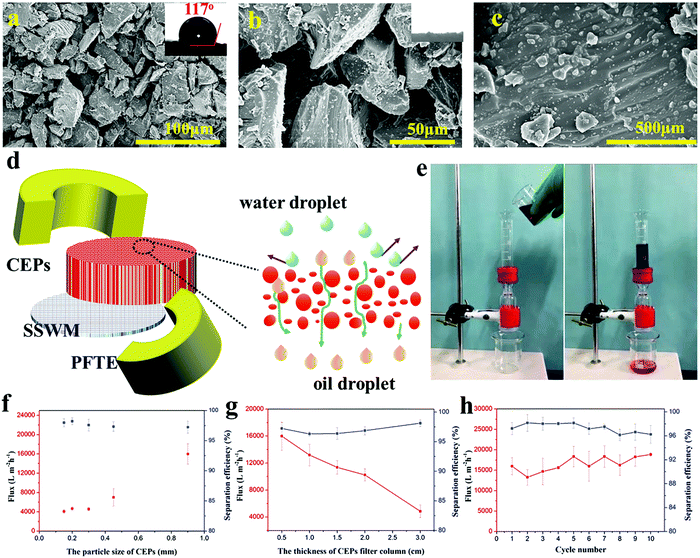
EP is widely used in industrial fields due to its excellent properties, but is difficult to break down due to the three-dimensional cross-linked structure. Thus, retired EP often appears rich in the garbage dump. In this experiment, waste EP was simply mechanically pulverized to obtain different sizes of CEPs. Taking advantage of their high hydrophobicity and superoleophilicity, CEPs were piled up to form a filter column and then used for the separation of an oil–water mixture. The surface morphologies of the CEP filter column are illustrated in Fig. 1a–c. The CEPs are of an irregular geometry with different sizes and thus can form different pore sizes ranging from nanometer to micron after accumulation. The largest pore size reaches up to 50 μm, so an oily liquid passed through the filter column quickly. Moreover, the high-magnification SEM image reveals that the surface of the CEPs is covered with nanoscale resin particles, forming a micro and nano hierarchical rough structure. This effectively increases the water repellent capacity of CEPs, preventing water passing through. Besides, the surface roughness of the CEP filter column was also observed by lLaser scanning confocal microscope (LSCM). It can be clearly seen that the surface of the CEP filter column is uneven with Sa of 34.1 μm (Fig. S1, ESI†). As a kind of oil–water separation material, the CEP filter column shows high hydrophobicity with a water contact angle (WCA) of 117° (Fig. 1a).To provide insight into the preparation and oil–water separation process of the CEP filter column, a hypothetical schematic diagram is illustrated in Fig. 1d. As described in the Experiment section, CEPs were assembled into a cylinder on stainless steel welde mesh (SSWM) and surrounded by polytetrafluoroethylene (PFTE) molds. Consequently, a three dimensional hard porous separation column was formed with superoleophilicity and high hydrophobicity. When the oil–water mixture contacts the surface of the CEP filter column, the oil droplets quickly pass under gravity driving, while the water is intercepted on the surface. For instance, a chloroform–water mixture was separated rapidly and efficiently through the CEP filter column (Fig. 1e and Movie S1, ESI†). To be an effective material for separating oil–water mixtures, it should meet two significant factors, i.e., high flux and high separation efficiency. Thus, we researched the influence of the particle size and thickness of the CEP filter column upon the separation flux and efficiency (Fig. 1f). With the increase of CEP size, the separation flux increases obviously from 4088 to 15![[thin space (1/6-em)]](https://www.rsc.org/images/entities/char_2009.gif) 987 L m−2 h−1 with no significant decline in separation efficiency. When the particle size increases to 0.9 mm, the separation efficiency of the CEP filter column is still up to 97%, suggesting good water rejection. The thickness of the CEP filter column shows obviously negative influences on separation flux (Fig. 1g), while the separation efficiency of the CEP filter column is only slightly improved at a high thickness. Agreeable oil–water separation performances of CEPs can be achieved by adjusting their particle size and stacking thickness. Moreover, the CEP filter column still maintains high flux and separation efficiency even after using for 10 cycles (Fig. 1h), indicating excellent stability and reusability. Besides, various wastes including thermosetting polymers and thermoplastics were chosen for separating the simple oil–water mixture, and all of them exhibited wonderful separation performances (Table S1, ESI†). Coupled with the unique features of thermosetting resin such as good mechanical properties, outstanding chemical stability, high temperature resistance, low shrinkage and mildew resistance, we anticipate that this work will provide an inexpensive and excellent material to treat the oily wastewater in many complex environments.
987 L m−2 h−1 with no significant decline in separation efficiency. When the particle size increases to 0.9 mm, the separation efficiency of the CEP filter column is still up to 97%, suggesting good water rejection. The thickness of the CEP filter column shows obviously negative influences on separation flux (Fig. 1g), while the separation efficiency of the CEP filter column is only slightly improved at a high thickness. Agreeable oil–water separation performances of CEPs can be achieved by adjusting their particle size and stacking thickness. Moreover, the CEP filter column still maintains high flux and separation efficiency even after using for 10 cycles (Fig. 1h), indicating excellent stability and reusability. Besides, various wastes including thermosetting polymers and thermoplastics were chosen for separating the simple oil–water mixture, and all of them exhibited wonderful separation performances (Table S1, ESI†). Coupled with the unique features of thermosetting resin such as good mechanical properties, outstanding chemical stability, high temperature resistance, low shrinkage and mildew resistance, we anticipate that this work will provide an inexpensive and excellent material to treat the oily wastewater in many complex environments.
Water-in-oil emulsion separation
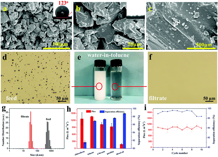
Ocean pollution and oily wastewater discharged from industrial production or domestic use are a grievous threat to environmental security and public health.35–38 On most occasions, these oil–water mixtures exist as stable emulsions. Because of the small size of droplets, the emulsion separation is more difficult. Seeing that the CEP filter column featured superlipophilicity, hydrophobicity and adjustable pore sizes, we used them in the separation of surfactant-stabilized water-in-oil emulsions. At the beginning, the emulsion is successfully separated by the CEP filter column, but over time, its separation efficiency decreases due to the passage of water droplets (Fig. S2a, ESI†). As for the phosphoric acid-modified particles (HEPs), they show good and stable emulsion separation ability (FHEPs Fig. S2b, ESI†). Accordingly, the optimal experiments on the particle size of HEPs and the thickness of the HEP filter column were conducted to achieve high flux and separation efficiency (Fig. S3, ESI†). As a result, we chose the particle size of 0.45 mm and the column thickness of 2 cm as basic conditions to separate water-in-oil emulsions. When the particle size of the HEPs decreases to 0.45 mm, the filter column shows smaller pore size and pleasant water repellency (WCA = 123°) (Fig. 2a–c and Fig. S4, ESI†).Various water-in-oil emulsions with different droplets sizes were prepared to estimate the separation performance of the HEP filter column. We chose water-in-toluene emulsion as the demonstration model (Fig. 2d–g and Movie S2, ESI†). It can be seen that the milky white stable emulsion (left) became a clear liquid (right) after the separation through the HEP filter column (Fig. 2e). To further visualize the transition of the emulsion state, optical images were observed (Fig. 2d and f). The water droplets evenly dispersed in toluene completely disappear after separation, indicating that the water is removed from the emulsion and the obtained filtrate is pure. Other water-in-oil emulsions, such as water-in-n-hexane, water-in-chloroform, water-in-gasoline and water-in-diesel, can also be effectively separated (Fig. S5, ESI†). The particle size analysis shows that the droplet size in the water-in-toluene emulsion is distributed in the range of 377 to 961 nm. In the filtrate, their size is below 50 nm, suggesting that HEPs can well separate an emulsion with the droplet size greater than 50 nm. Additionally, the particle size distribution of water-in-n-hexane/chloroform/gasoline/diesel emulsions was also tested (Fig. S6, ESI†). The results indicate that the HEP filter column can achieve the separation of not only micron-emulsions, but also nano-emulsions.
In order to evaluate the separation performance, the flux and separation efficiency of all the emulsions were tested (Fig. 2h). Among the tested emulsions, the flux for water-in-toluene/chloroform/n-hexane/gasoline (1366, 1270, 1031 and 936 L m−2 h−1 accordingly) are all higher than that of other separation materials.39–43 The flux of the highly viscous diesel oil is relatively low since the flux is sensitive to the viscosity of the solvent. This is also observed in other reports.44,45 High separation efficiency demonstrates the ability of the HEP filter column to remove water efficiently from the oil. Moreover, the separation efficiency can be further increased by conveniently adjusting the HEP particle size and the filter column thickness to form multi-scale pores and curving pore channels. More importantly, the HEP filter column could be recovered by simple ethanol cleaning. After 10 cycling tests, it still maintains effective flux and separation efficiency, indicating excellent reusability (Fig. 2i). Additionally, fiber-reinforced EP composites (such as glass fiber reinforced epoxy resin) treated with sulfuric acid or nitric acid, also show excellent performance for water-in-oil emulsion separation (Table S2, ESI†).
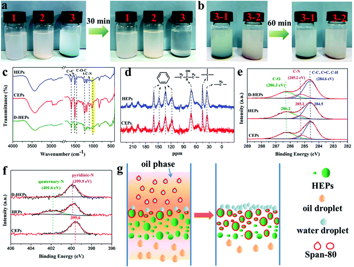
To further prove the demulsification mechanism, HEPs and CEPs were put into the water-in-oil emulsion respectively. A demulsification behavior was observed within 30 min for the HEPs while the emulsion was still turbid for the CEPs (Fig. 3a). However, when HEPs were treated with alkali (D-HEPs), the emulsion remained milky even after 60 min (Fig. 3b). To determine the reason why HEPs could make the emulsion separate, we analyzed their chemical structures by Fourier transform infrared spectroscopy (FT-IR), solid-state NMR and X-ray photoelectron spectroscopy (XPS). Through the above test methods, it can be seen that the characteristic peaks of EP, such as the benzene ring, C–O–C and C–N bonds remain intact in the HEPs, confirming that the CEPs were not degraded but modified after being treated with acid (Fig. 3c–f and Fig. S7, ESI†). Furthermore, the FT-IR and XPS N 1s spectra reveal that tertiary N in the CEPs interacts with phosphoric acid to form the corresponding quaternary ammonium salt. As a contrast, the peaks belonging to phosphate in FT-IR and the quaternary-N in the XPS N 1s spectrum disappear for D-HEPs. Besides, HEPs after emulsion separation (A-HEPs) were tested by FT-IR (Fig. S8, ESI†). A new peak ascribed to a C![[double bond, length as m-dash]](https://www.rsc.org/images/entities/char_e001.gif) O bond of span-80 appears at 1732 cm−1, indicating that span-80 is absorbed by HEPs during separation. Therefore, it was concluded that the protonation of CEPs makes a contribution to the better oil–water separation performance. Based on the above results, we propose a possible mechanism of HEPs for the separation of water-in-oil emulsions (Fig. 3g). When the emulsion is in contact with the HEP filter column surface, HEPs could interact with amphiphilic surfactant span-80, destroying the stability of the oil–water interface and thus leading to emulsion droplet demulsification. So the oil droplets spread out quickly and flow into the collector through curving pore channels due to the superlipophilicity of the HEPs. Whereas, the water droplets are blocked in the HEP filter column surface layer.
O bond of span-80 appears at 1732 cm−1, indicating that span-80 is absorbed by HEPs during separation. Therefore, it was concluded that the protonation of CEPs makes a contribution to the better oil–water separation performance. Based on the above results, we propose a possible mechanism of HEPs for the separation of water-in-oil emulsions (Fig. 3g). When the emulsion is in contact with the HEP filter column surface, HEPs could interact with amphiphilic surfactant span-80, destroying the stability of the oil–water interface and thus leading to emulsion droplet demulsification. So the oil droplets spread out quickly and flow into the collector through curving pore channels due to the superlipophilicity of the HEPs. Whereas, the water droplets are blocked in the HEP filter column surface layer.
Superhydrophobic CEP coatings with diverse water adhesion
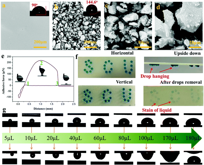
Superhydrophobic surfaces, especially those with adjustable water adhesion, have been widely studied in recent years due to their wide applications. Generally, the control of water adhesion is achieved by adjusting the surface microstructure.46–49 Different from the previous strategy, we herein fabricated superhydrophobic surfaces with diverse water adhesion by choosing different adhesives for gluing hydrophobic CEPs. High water adhesion coatings (HA-CEPs) were synthesized by combining waste CEPs with EP adhesive. SEM and LSCM images of the EP adhesive layer present a smooth surface, with a WCA of 90° (Fig. 4a and Fig. S10, ESI†). After attaching CEPs of different sizes, a rough surface is formed (Fig. S9–S11, ESI†). Owing to the deep and wide pitch of HA-CEPs formed by large size CEPs, the water droplet is permeated in the microstructure, showing poor water repellency (Fig. S12, ESI†). As a result, the hydrophobic degree of the coating is sensitive to the CEP particle size. As for HA-CEPs with the size ranging from 0.038–0.075 mm, its hydrophobicity is further improved (WCA = 144.6°) due to the decrease of the solid–liquid contact area. We then investigated the morphologies and microstructure of the HA-CEPs (Fig. 4b–d). At low magnification, it can be seen that the HA-CEPs have a micron-scale rough surface. After further magnifying, some nano-scale particles strongly anchored on the micron-scale CEPs are observed, serving as a secondary structure. This mixed hierarchical structure and hydrophobicity of the CEPs explains the strong water repellency of HA-CEPs.Aside from hydrophobicity, the water adhesion is another useful function to estimate the affinity to water droplets of HA-CEPs.50 As displayed in Fig. 4e, the force was kept at zero in the initial ascent, because the water droplet was suspended in air with no contact with the HA-CEPs. When contacted with the water droplet, the force dropped rapidly, which showed that the water droplet was backed by HA-CEPs. To make full contact with the water droplet, the CEP coating increased slightly by 0.1 mm. Then, HA-CEPs moved down at a certain speed to separate the water droplet from its surface. In this process, the force increased gradually. Until the water droplet was on the point of separating from the coating, the force reaches the maximum value (219 μN), which is defined as the adhesive force of HA-CEPs. Furthermore, the logo “SCU” consisting of water droplets could be fixed on HA-CEPs when vertical or upside down, which is due to the partial wetting behavior (Fig. 4f). Thus, HA-CEPs combined with excellent hydrophobicity and high water adhesion have many potential applications, such as water droplet storage and droplet transportation. In the case of water droplet storage, the maximum water volume can reach 50 μL without any dripping when the HA-CEPs inclined to 90° or 180° (Fig. S13, ESI†). For the droplet transportation, HA-CEPs can transfer the water droplet from the superhydrophobic surface (with low water adhesion) to the hydrophilic glass substrate (Fig. S14, ESI†). To further test the droplet transportation capacity, water droplets of different volumes were placed on a superhydrophobic surface, and then touched by HA-CEPs. It can be seen that the transport volume of HA-CEPs to water is up to 170 μL (Fig. 4g). In addition, HA-CEPs also exhibit excellent acid and alkali corrosion resistance (Fig. S15, ESI†). Therefore, this coating should be extended to transport acid or alkali liquids.
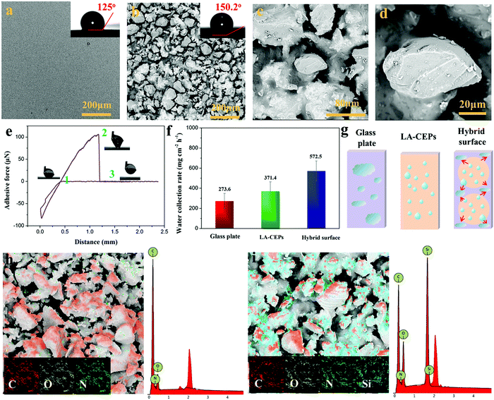
Besides HA-CEPs, the CEPs can be used to prepare a superhydrophobic coating with low water adhesion using polydimethylsiloxane (PDMS) as the adhesive (LA-CEPs). As shown in Fig. 5a and Fig. S16a (ESI†), the PDMS adhesive layer is also flat and smooth with low roughness. But owing to its low surface energy, the WCA is 125°, which is higher than that of the EP adhesive layer. After CEP deposition, the coating became uneven and rough, and thus the WCA of the LA-CEPs increases to 150.2° (Fig. 5b and Fig. S16b, ESI†). As observed in HA-CEPs, LA-CEPs also show the same secondary structure (Fig. 5c and d). Considering the flexibility and feasibility of improving the surface hydrophobicity, other waste thermosetting polymers and their composite materials or thermoplastics can also be used to build superhydrophobic coatings (Fig. S17, ESI†). This route should not only recycle the wastes, but also introduce new functional particles to expand the application fields of hydrophobic surfaces.
Fig. 5e displays the adhesive force as a function of distance for LA-CEPs. It can be seen that the adhesive force of LA-CEPs is ∼106 μN and lower than that of HA-CEPs. Furthermore, as illustrated in Fig. S18 (ESI†), LA-CEPs demonstrate poor ability of water droplet storage. Water of 5 μL is still stable on the LA-CEPs, whether they incline to 90° or 180°. But when the water volume increases to 6 μL, it rolls off as the LA-CEPs are tilted to 64°. Therefore, LA-CEPs exhibit the potential to be used for water collection. The equipment for LA-CEPs to collect water is shown in Fig. S19 (ESI†). As expected, the water collection rate of LA-CEPs is ∼371.4 g m−2 h−1, which is better than that of a superhydrophilic glass substrate. The glass plate with two LA-CEP circle patterns (hybrid surface) tended to exhibit further enhancement in the water collection rate, reaching 572.5 m−2 h−1 (Fig. 5f). As the fog droplets touched, the water collection process on three kinds of surfaces is schematically proven in Fig. 5g. The fog droplets spread rapidly on the superhydrophilic glass substrate, forming a water film. In contrast, the superhydrophobic HA-CEPs can catch large amounts of tiny fog droplets. On the hybrid surface with the wettability gradient, fog droplets are captured on two LA-CEP circle patterns and further directionally collected on the hydrophilic regions, resulting in relatively high water collection rate.51
The HA-CEPs and LA-CEPs possess the same microstructure, but show diverse water adhesion due to different adhesive layers. So it is important to investigate the role of the adhesive in the CEP coatings. Energy dispersive spectrometry (EDS) was employed to analyze the chemical composition of the CEP coatings. HA-CEPs are composed of C, O and N, similar to the EP adhesive (Fig. 5h). Meanwhile, the LA-CEPs display a new element peak of Si, which is from the PDMS adhesive that covered on the CEP surface by capillary force (Fig. 5i). Therefore, the CEP coatings covered with relatively high surface energy EP adhesive (23.62 mN m−1) show high water adhesion, while it shows low water adhesion with low surface energy PDMS adhesive (17.90 mN m−1).
Acidic liquid/gas detection
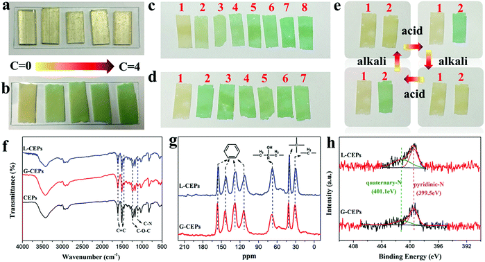
Monitoring materials have drawn much attention since they can visually respond to the changes of surrounding environments and achieve early warning.52–55 In the experiments, we found that the CEPs showed a unique response to the acid liquid, while the EP block did not (Fig. 6a). Fig. 6b displays the response behavior of the CEP coating when immersed in hydrochloric acid solution. Once exposed to the acid, the color of the CEPs changes from yellow to green. Further increasing the acid concentration to 4 mol L−1, its color becomes dark green. Therefore, different concentrations of acid can be identified according to the color changes. Moreover, CEPs can resolve the problem of distinguishing different kinds of acids. CEPs produced disparate sensitivity toward various acids, which can be explained by differences of acid properties, such as the ability to release H+, oxidation and corrosion. The visible discoloration of the CEPs occurs only within 30 s in nitric acid, but no obvious color changes even when placed in acetic acid for 5 h (Fig. S20, ESI†).More than that, CEPs can be used to monitor acid gas, which provides visual warning at room temperature without precise equipment. To estimate the sensitivity of CEPs, at first, we recorded the discoloration time of CEPs when put into a closed container containing acid gas. In just 5 s, the color of the CEPs turned to light green. Further extending the time, their color was deepened (Fig. 6c). Next, by adjusting the amount of hydrochloric acid, the detection limit of the CEPs was tested (Fig. 6d). CEPs were sensitive enough to detect the gas produced by 0.5 mL hydrochloric acid in 30 s. These results confirm that CEPs exhibit fast response speed and low detection limit to acid gas. We speculate that CEPs will exhibit more excellent sensitivity with further reducing the particles size to expose more responsive groups. In consideration of the service life of CEPs, their reusability was explored. As the acid gas flowed to the CEP surface, the color of the CEPs was green. Upon contacting alkaline gas (NH3), the color of the CEPs changed from green to yellow. In this way, the CEPs returned to their initial state. The process can be recycled many times (Fig. 6e). Additionally, owing to the reversible color changes and excellent reusability, the CEPs after acid treatment have potential in NH3 sensing.
To explore the reason for such fast and visual responsive behavior, FT-IR, 13C-NMR and XPS were used to analyze the structure change of the CEPs. The CEPs after treatment with acid liquid and gas were labeled as L-CEPs and G-CEPs, respectively. Whereas, in FT-IR (Fig. 6f), 13C-NMR (Fig. 6g), survey spectra (Fig. S21a, ESI†) and high-resolution C 1s spectra (Fig. S21b, ESI†), there is no change in the structure of the CEPs. As further observed in the N 1s spectra, a new peak attributed to quaternary-N appears in the L-CEPs and G-CEPs (Fig. 6h). Therefore, the sensing response of CEPs is a consequence of protonation between the tertiary N in the CEPs and H in the acids, which is different from the oxidation-heterolysis mechanism previously reported.56 Under a nitrogen atmosphere, CEPs still discolor when contacting acid. However, the molecular structure that causes the discoloration is not clear. Presumably, 4,4-diaminodiphenylmethane plays a leading role in the pH-responsive behavior.
Information storage
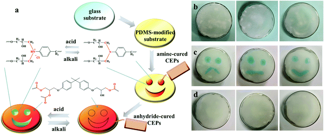
Benefiting from acid-responsive behavior, CEPs exhibit a bright future in information storage. Fig. 7a illustrated the preparation process and working principles of the coating containing information. Amine-cured and anhydride-cured CEPs were orderly painted on the PDMS-modified glass substrate, and then the uniform surface was obtained after curing. The tertiary N in amine-cured CEPs could react with acid liquid or gas to change the color, while anhydride-cured CEPs are insensitive to acid. Thus, the hidden information appeared. After exposure to an alkaline environment, the coating returned to its initial state. As displayed in Fig. 7b–d, all kinds of expressions are invisible at first, but the green patterns appear shortly after immersing in hydrochloric acid solution. Due to the deprotonation under alkaline conditions, the expressions disappear again when contacted with sodium hydroxide solution. As evidenced by the above results, CEPs have a potential application in anti-forgery and information storage.Conclusions
Environmental friendliness, high-value reutilization and ease of industrialization are the goals in the recycling of waste materials. In this work, we used the simplest route, that is, mechanical crushing to prepare multifunctional materials on the basis of retaining the excellent performances of the commercially available resin itself. The waste resin can be transformed into a porous filter column for efficient separation of simple oil–water mixture and surfactant-stabilized emulsions. Moreover, micron or nanometer scale CEPs can also be used to construct superhydrophobic surfaces. The adhesion can be regulated by using different adhesives, and then the CEP coating can be applied in different fields, such as droplet transportation and water collection. Furthermore, different from anhydride-cured CEPs, amine-cured CEPs could monitor acid liquid and gas due to its unique reversible response to acid. Thus, the coating combining these two kinds of resins can also play a role in the field of information storage. This work updates our understanding of refuse reclamation. First, owning to the inherent and derived characteristics of waste materials, they can be reused in the corresponding fields and may even become irreplaceable functional materials. Second, for high value reutilization, it is not necessary to crack or degrade wastes into small molecules. Simple crushing or modification not only retains the structural advantages of the resin itself, but also can be reused in high-tech fields.Conflicts of interest
There are no conflicts to declare.Acknowledgements
This work was supported by the National Natural Science Foundation of China (No. 51721091), te State Key Laboratory of Polymer Materials Engineering Open Fund project (sklpme2020-1-02) and the Fundamental Research Funds for the Central Universities.References
- Z. Xu, Y. Liang, X. Ma, S. Chen, C. Yu, Y. Wang, D. Zhang and M. Miao, Nat. Sustain., 2020, 3, 29–34 CrossRef.
- Q. Shi, K. Yu, X. Kuang, X. Mu, C. K. Dunn, M. L. Dunn, T. Wang and H. Jerry Qi, Mater. Horiz., 2017, 4, 598–607 RSC.
- B. Wang, S. Ma, S. Yan and J. Zhu, Green Chem., 2019, 21, 5781–5796 RSC.
- K. Yang, J. Guan, K. Numata, C. Wu, S. Wu, Z. Shao and R. O. Ritchie, Nat. Commun., 2019, 10, 1–12 CrossRef.
- H. Sardon and A. P. Dove, Science, 2018, 360, 380–381 CrossRef CAS.
- J. Zheng and S. Suh, Nat. Clim. Change, 2019, 9, 374–378 CrossRef.
- E. A. Olivetti and J. M. Cullen, Science, 2018, 360, 1396–1398 CrossRef CAS.
- W. A. Ogden and Z. Guan, J. Am. Chem. Soc., 2018, 140, 6217–6220 CrossRef CAS.
- X. Xu, S. Ma, S. Wang, J. Wu, Q. Li, N. Lu, Y. Liu, J. Yang, J. Feng and J. Zhu, J. Mater. Chem. A, 2020, 8, 11261–11274 RSC.
- S. Wang, S. Ma, Q. Li, X. Xu, B. Wang, W. Yuan, S. Zhou, S. You and J. Zhu, Green Chem., 2019, 21, 1484–1497 RSC.
- B. Krishnakumar, M. Singh, V. Pathasarthy, C. Park, N. G. Sahoo, G. J. Yun and S. Rana, Nanoscale Adv., 2020, 2, 2726–2730 RSC.
- J. B. Zhu, E. M. Watson, J. Tang and E. Y. X. Chen, Science, 2018, 360, 398–403 CrossRef CAS.
- K. Ragaert, L. Delva and K. Van Geem, Waste Manag., 2017, 69, 24–58 CrossRef CAS.
- G. Oliveux, L. O. Dandy and G. A. Leeke, Prog. Mater. Sci., 2015, 72, 61–99 CrossRef CAS.
- P. Hadi, M. Xu, C. S. K. Lin, C. W. Hui and G. McKay, J. Hazard. Mater., 2015, 283, 234–243 CrossRef CAS.
- J. Li, H. Lu, J. Guo, Z. Xu and Y. Zhou, Environ. Sci. Technol., 2007, 41, 1995–2000 CrossRef CAS.
- D. K. Ratnasari, M. A. Nahil and P. T. Williams, J. Anal. Appl. Pyrolysis, 2017, 124, 631–637 CrossRef CAS.
- L. Long, S. Sun, S. Zhong, W. Dai, J. Liu and W. Song, J. Hazard. Mater., 2010, 177, 626–632 CrossRef CAS.
- Y. N. Kim, Y. O. Kim, S. Y. Kim, M. Park, B. Yang, J. Kim and Y. C. Jung, Compos. Sci. Technol., 2019, 173, 66–72 CrossRef CAS.
- I. Okajima, K. Watanabe, S. Haramiishi, M. Nakamura, Y. Shimamura and T. Sako, J. Supercrit. Fluids, 2017, 119, 44–51 CrossRef CAS.
- K. Li, L. Zhang and Z. Xu, J. Hazard. Mater., 2019, 374, 356–364 CrossRef CAS.
- T. Liu, X. Guo, W. Liu, C. Hao, L. Wang, W. C. Hiscox, C. Liu, C. Jin, J. Xin and J. Zhang, Green Chem., 2017, 19, 4364–4372 RSC.
- F. Tian, X. L. Wang, Y. Yang, W. An, X. Zhao, S. Xu and Y. Z. Wang, ACS Sustainable Chem. Eng., 2020, 8, 2226–2235 CrossRef CAS.
- J. Jiang, G. Deng, X. Chen, X. Gao, Q. Guo, C. Xu and L. Zhou, Compos. Sci. Technol., 2017, 151, 243–251 CrossRef CAS.
- X. Chen, S. Chen, Z. Xu, J. Zhang, M. Miao and D. Zhang, Green Chem., 2020, 22, 4187–4198 RSC.
- B. Wang, S. Ma, X. Xu, Q. Li, T. Yu, S. Wang, S. Yan, Y. Liu and J. Zhu, ACS Sustainable Chem. Eng., 2020, 8, 11162–11170 CrossRef CAS.
- M. Das, R. Chacko and S. Varughese, ACS Sustainable Chem. Eng., 2018, 6, 1564–1571 CrossRef CAS.
- J. Li, P. L. Xu, Y. K. Zhu, J. P. Ding, L. X. Xue and Y. Z. Wang, Green Chem., 2012, 14, 3260–3263 RSC.
- P. Xu, J. Li and J. Ding, Compos. Sci. Technol., 2013, 82, 54–59 CrossRef CAS.
- J. N. Lo, S. R. Nutt and T. J. Williams, ACS Sustainable Chem. Eng., 2018, 6, 7227–7231 CrossRef CAS.
- D. H. Kim, M. Lee and M. Goh, ACS Sustainable Chem. Eng., 2020, 8, 2433–2440, DOI:10.1021/acssuschemeng.9b06371.
- J. H. Zhu, P. Y. Chen, M. N. Su, C. Pei and F. Xing, Green Chem., 2019, 21, 1635–1647 RSC.
- X. Zhao, X. L. Wang, F. Tian, W. L. An, S. Xu and Y. Z. Wang, Green Chem., 2019, 21, 2487–2493 RSC.
- X. Kuang, Y. Zhou, Q. Shi, T. Wang and H. J. Qi, ACS Sustainable Chem. Eng., 2018, 6, 9189–9197 CrossRef CAS.
- J. Li, C. Xu, C. Guo, H. Tian, F. Zha and L. Guo, J. Mater. Chem. A, 2017, 6, 223–230 RSC.
- F. Li, Z. Wang, S. Huang, Y. Pan and X. Zhao, Adv. Funct. Mater., 2018, 28, 1–7 Search PubMed.
- W. Zhang, N. Liu, Q. Zhang, R. Qu, Y. Liu, X. Li, Y. Wei, L. Feng and L. Jiang, Angew. Chem., Int. Ed., 2018, 57, 5740–5745 CrossRef CAS.
- F. Tian, Y. Yang, X. L. Wang, W. L. An, X. Zhao, S. Xu and Y. Z. Wang, Mater. Horiz., 2019, 6, 1733–1739 RSC.
- Y. Cai, D. Chen, N. Li, Q. Xu, H. Li, J. He and J. Lu, J. Mater. Chem. A, 2016, 4, 18815–18821 RSC.
- X. Lin, J. Heo, H. Jeong, M. Choi, M. Chang and J. Hong, J. Mater. Chem. A, 2016, 4, 17970–17980 RSC.
- H. Ye, D. Chen, N. Li, Q. Xu, H. Li, J. He and J. Lu, Environ. Sci.: Nano, 2019, 6, 1259–1266 RSC.
- J. Li, Z. Zhao, D. Li, H. Tian, F. Zha, H. Feng and L. Guo, Nanoscale, 2017, 9, 13610–13617 RSC.
- W. Zhang, Z. Shi, F. Zhang, X. Liu, J. Jin and L. Jiang, Adv. Mater., 2013, 25, 2071–2076 CrossRef CAS.
- W. Zhang, N. Liu, Y. Cao, Y. Chen, L. Xu, X. Lin and L. Feng, Adv. Mater., 2015, 27, 7349–7355 CrossRef CAS.
- M. Tao, L. Xue, F. Liu and L. Jiang, Adv. Mater., 2014, 26, 2943–2948 CrossRef CAS.
- J. Long, P. Fan, D. Gong, D. Jiang, H. Zhang, L. Li and M. Zhong, ACS Appl. Mater. Interfaces, 2015, 7, 9858–9865 CrossRef CAS.
- J. N. Wang, Y. Q. Liu, Y. L. Zhang, J. Feng, H. Wang, Y. H. Yu and H. B. Sun, Adv. Funct. Mater., 2018, 28, 1–8 Search PubMed.
- Y. Tan, B. Hu, Z. Chu and W. Wu, Adv. Funct. Mater., 2019, 29, 1–10 Search PubMed.
- C. Chen, M. Liu, L. Zhang, Y. Hou, M. Yu and S. Fu, ACS Appl. Mater. Interfaces, 2019, 11, 7431–7440 CrossRef CAS.
- M. Cheng, M. Song, H. Dong and F. Shi, Small, 2015, 11, 1665–1671 CrossRef CAS.
- H. Bai, L. Wang, J. Ju, R. Sun, Y. Zheng and L. Jiang, Adv. Mater., 2014, 26, 5025–5030 CrossRef CAS.
- X. Liu, G. Su, Q. Guo, C. Lu, T. Zhou, C. Zhou and X. Zhang, Adv. Funct. Mater., 2018, 28, 1–10 Search PubMed.
- H. Yuan, J. Tao, N. Li, A. Karmakar, C. Tang, H. Cai, S. J. Pennycook, N. Singh and D. Zhao, Angew. Chem., 2019, 131, 14227–14232 CrossRef.
- X. Liu, C. Lu, X. Wu and X. Zhang, J. Mater. Chem. A, 2017, 5, 9824–9832 RSC.
- M. E. Genovese, E. Colusso, M. Colombo, A. Martucci, A. Athanassiou and D. Fragouli, J. Mater. Chem. A, 2017, 5, 339–348 RSC.
- K. Zheng, Q. Zou, Y. Yang, Y. Mao, J. Zhang and J. Cheng, Ind. Eng. Chem. Res., 2018, 57, 13283–13290 CrossRef CAS.
Footnote |
| † Electronic supplementary information (ESI) available. See DOI: 10.1039/d0mh01053g |
| This journal is © The Royal Society of Chemistry 2021 |

