
The impact of cation–π, anion–π, and CH–π interactions on the excited-state intramolecular proton transfer of 1,4-dihydroxyanthraquinone†
Asiyeh
Shahraki
 ,
Ali
Ebrahimi
*,
Shiva
Rezazadeh
and
Roya
Behazin
,
Ali
Ebrahimi
*,
Shiva
Rezazadeh
and
Roya
Behazin
Department of Chemistry, Computational Quantum Chemistry Laboratory, University of Sistan and Baluchestan, P.O. XZBox, 98135-674, Zahedan, Iran. E-mail: ebrahimi@chem.usb.ac.ir; Fax: +98 54 33446565
First published on 16th November 2020
Abstract
The impact of cation–π, anion–π, and CH–π interactions on the photophysical properties of quinizarin have been investigated using the density functional theory (DFT) and time-dependent density functional theory (TD-DFT) at the M06-2X/6-311++G(d,p) level in the gas phase and solution. The complexation of quinizarin with some mono- and divalent ions (including Na+, K+, Mg2+, Ca2+, F−, Cl−, and Br−) and the CF3H molecule leads to unfavorable proton transfers in the ground state. Excitation reinforces the intramolecular hydrogen bond in the complexes and facilitates proton transfer in the first excited state. The complexes exhibit exothermic excited-state proton transfer in the solution. The cation–π, anion–π, and CH–π interactions affect the absorption and emission bands and provide a wide tunable range of fluorescence emission. The large Stokes shift is an important property of the complexes that indicates their desirable fluorescence properties. The complexes involved in anion–π interactions possess the largest Stokes shift in the solution.
Design, System, ApplicationExcited-state intramolecular proton transfer (ESIPT) is a basic mechanism commonly applied in the design of fluorescent sensors, laser dyes, ultraviolet photo-stabilizers, and probes for biological environments. Molecular systems with ion–π interactions are designed to determine their effects on the optical and fluorescence properties of desired compounds. In this work, the effect of ion–π and CH–π interactions on the photophysical properties of some ion–π complexes of quinizarin have been studied via the elaboration of the ESIPT process in order to improve the fluorescence properties of quinizarin. The absorption and fluorescence spectra obtained using the TD-DFT method at the M06-2X/6-311++G(d,p) level of theory in the gas phase and solution indicate improvement in the fluorescence properties of quinizarin via ion–π interactions in the solution. |
Introduction
Excited-state intramolecular proton transfer (ESIPT) usually forms the basis in the design of fluorescent sensors,1–3 laser dyes,4,5 high-energy radiation detectors,6 ultraviolet photostabilizers,7–9 probes for biological environments,10 and organic light-emitting devices.11 This process was first observed in an experimental study of salicylic acid by Weller et al.12 Subsequently, both experimental and theoretical methods have been widely used to investigate inter and intramolecular photo-induced proton transfer processes.13–19 ESIPT is an ultrafast photochemical process induced by the hydrogen bond, which has critical roles in physical, chemical, and biological processes. It has been reported by Zhao et al. that the excited-state reinforcement of hydrogen bonds can promote intramolecular proton transfer.20 This process occurs in a four-level cycle, including absorption, ESIPT, emission, and ground-state intramolecular proton transfer (GSIPT).21–23 ESIPT fluorophores have special photophysical properties, such as large Stokes shift24 and dual fluorescence,25 which lead to their crucial applications in LEDs,26 molecular switches27 and fluorescence imaging.28 Due to its importance in chemistry, biochemistry, and biology, ESIPT has been extensively investigated in some organic molecules, such as anthraquinones,29–33 benzazoles,34 benzoxazoles,35–37 flavones,38 and imidazoles.39,40Quinonoids are important molecules due to their role in biological processes, such as energy conversions in living organisms,41,42 and their wide industrial usage as coloring materials43,44 and redox agents.45,46 The antitumor and antigenotoxic47,48 activities of hydroxyanthraquinones and their structural similarity to the functional motifs of various anthracycline antitumor drugs49,50 have made them significant in chemical and biochemical sciences. In addition, anthraquinone dyes are very important chromophoric molecules with reasonable fluorescence yields.51–54 Moreover, hydroxyanthraquinone derivatives participate in intriguing excited-state processes associated with inter and intramolecular hydrogen bond interactions.55–57 The impact of substituents on the absorption and fluorescence spectra of hydroxyanthraquinones has already been investigated.58–60 The ESIPT potential barrier and fluorescent radiation can be affected by substituents in the different positions, which eventually change the photochemical and photophysical properties of the molecule.59,60
1,4-Dihydroxyanthraquinone (quinizarin, Q) can be used as a fungicide, pesticide, dye, photoinitiator, and as an additive in lubricants.61–63 Quinizarin makes fluorescent complexes with lithium, boron, and aluminum; thus, it can be used as a spectrophotometric analytical reagent for the determination of the mentioned elements.62,64–67 Photoexcitation in the first excited singlet (S1) state induces the ESIPT process in quinizarin.55,68 Chemical modifications have an effect on the excited-state dynamics and are useful in designing new compounds with desirable fluorescence emissions. It is notable that the reaction dynamics of the ESIPT process and the fluorescence of the molecules can be affected by taking into account of non-covalent interactions, such as cation–π and anion–π, which are ubiquitous in chemistry, biology, and materials science. The π-interactions are one of the most important chemical classes of non-covalent interactions that contribute to the structure and properties of π-conjugated materials used in photonics.69,70 In this work, the effect of ion–π and CH–π interactions on the photophysical properties of some ion–π complexes of quinizarin have been studied via the elaboration of ESIPT processes, and these interactions may improve the optical and fluorescence properties of quinizarin.
Computational methods
Geometries of all compounds in the ground (S0) and excited (S1) states were optimized using the density functional theory (DFT) and time-dependent DFT (TDDFT) methods in conjunction with the M06-2X functional and the 6-311++G(d,p) basis set in the Gaussian09 program package.71 M06-2X is a suitable functional for reproducing the experimental excitation band shapes with TD-DFT.72–74 Moreover, the M06-2X functional has been suggested to evaluate noncovalent interactions well.75The solvent effect on the ground and excited states was considered according to the solvation model based on density (SMD) in water. SMD is a universal model due to its applicability to any charged or uncharged solute in any solvent for which a few key descriptors are known.76 There were no constraints on the bond lengths, bond angles, and dihedral angles during optimization. The vibrational frequency calculations were performed to validate all the local minima using the no imaginary frequency mode. The vertical excitation energies were computed based on the S0-state optimized geometries. To describe the dynamic ESIPT reactions in the gas phase and solution, the potential energy curves (PECs) in the S0 and S1 states were constructed via the relaxed scan of O1′–H1 lengths with a step size of 0.05 Å using the optimized ground- and excited-state geometries. The quantum theory of atoms in molecules (QTAIM) method77 was applied to analyze the topological electron distributions on the wave functions obtained at the M06-2X/6-311++G(d,p) level using the AIMALL suite of programs.78
Results and discussion
Three potential positions for the π-interaction of quinizarin (Q) with some mono- and divalent ions (including Na+, K+, Mg2+, Ca2+, F−, Cl−, and Br−) and the CF3H molecule along with atom numbering are depicted in Scheme 1. According to the positions, the complexes were divided into three types a, b, and c. The intramolecular proton transfer was considered in the ground (S0) and first singlet excited (S1) states of the complexes in the gas phase and solution. Some complexes are not stable in the S0 and S1 states. The stable complexes of each type are given in Table 1. | ||
| Scheme 1 Representation of the ESIPT process and the numbering of the atoms that participate in the intramolecular hydrogen bond. a–c represent the sites of Q interacting with the X species. | ||
| Type | X | |
|---|---|---|
| GS | ES | |
| The bold cases represent complexes stable both in the gas phase and solution. The italic cases correspond to complexes stable in solution. | ||
| a | Na + , K+, Mg2+, Ca2+, F−, CF3H | Na + , K+, Mg2+, Ca2+, F−, CF3H |
| b | K+, Mg2+, Ca2+, F−, Cl−, Br− | Mg2+, Ca2+, F−, Cl−, Br− |
| c | Na + , K+, Mg2+, Ca2+, F−, CF3H | Na + , K+, Mg2+, Ca2+, F−, Cl−, Br− |
The cation–π-a and CH–π-a complexes were stable in the S0 and S1 states in both phases, while the anion–π-a complexes were not stable in both phases, with the exception of Q–F−, which was stable only in solution. The numbers of stable complexes of type b were lower than those of type a in both the ground and excited states. Although all complexes were stable in the ground state in both phases, the complexes of type b were stable even in the excited state in solution. No stable structure of the Q–CF3H-b complex was observed in the ground and excited states. According to Table 1, all complexes of type c were stable in the ground state in both phases, with the exception of Q–Cl− and Q–Br−. Also, the excited-state anion–π-c complexes were observed only in solution.
Geometrical parameters
Intramolecular hydrogen bonds (IHB) are the driving force of the ESIPT reaction in a molecule. Thus, the characterization of hydrogen bond parameters is necessary for a deeper understanding of the proton transfer behavior of complexes. The most important structural parameters of the normal (N) form of type a complexes in the ground and excited states are reported in Table 2.|
|
|||||
|---|---|---|---|---|---|
| X | d 1/Å | d 2/Å | d 3/Å | θ 1/° | θ 2/° |
| The bold values correspond to the S1 state of the complexes. The data in parentheses are calculated in solution. | |||||
| Q | 0.978 (0.979) | 1.732 (1.734) | 143.95 (143.77) | ||
| 1.017 (1.028) | 1.554 (1.516) | 151.76 (153.08) | |||
| Na+ | 0.976 (0.978) | 1.781 (1.749) | 2.371 (2.564) | 141.46 (143.03) | 90.05(95.02) |
| 0.991 (1.017) | 1.687 (1.557) | 2.306 (2.491) | 145.61 (151.53) | 90.18 (90.98) | |
| K+ | 0.976 (0.978) | 1.776 (1.745) | 2.858 (2.928) | 141.73 (143.29) | 88.76 (92.47) |
| 0.993 (1.019) | 1.672 (1.549) | 2.760 (2.877) | 146.45 (151.87) | 89.56 (90.84) | |
| Mg2+ | 0.977 (0.978) | 1.823 (1.753) | 1.900 (2.777) | 139.13 (142.91) | 90.00 (111.77) |
| (1.015) | (1.564) | (2.733) | (151.20) | (111.85) | |
| Ca2+ | 0.976 (0.980) | 1.823 (1.730) | 2.326 (3.264) | 139.39 (143.90) | 89.34 (91.81) |
| 0.979 (1.026) | 1.813 (1.522) | 2.306 (3.270) | 138.60 (152.85) | 91.12 (88.91) | |
| F− | (0.979) (1.028) | (1.733) (1.515) | (3.349) (3.371) | (143.82) (153.16) | (89.87) (86.03) |
| CF3H | 0.978 (0.979) | 1.740 (1.726) | 2.325 (2.375) | 143.65 (144.35) | 87.10 (85.75) |
| 1.013 (1.025) | 1.569 (1.520) | 2.294 (2.332) | 151.14 (153.12) | 85.79 (85.19) | |
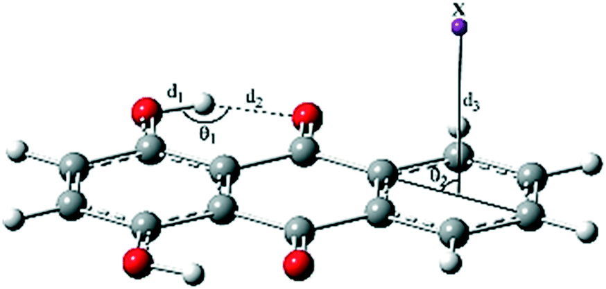
The O1–H1 bond length (d1), H1⋯O1′ distance (d2), and δ (O1–H1⋯O1′) bond angle (θ1) were respectively 0.978, 1.732 Å, and 143.95° for Q in the S0 state. The cation–π and CH–π interactions slightly decreased the parameters d1 and θ1 and increased d2, i.e. weakened IHB (labeled as O1–H1⋯O1′). Complexation with the divalent cations Mg2+ and Ca2+ induced larger changes in the geometrical parameters than did complexation with the monovalent cations K+ and Na+.
As seen in Table 2, the anionic complex Q–F− was only formed in solution with negligible changes in the geometrical parameters of component Q. The least changes were observed for the Q–CF3H complex. In addition, the distance of X from the center of the ring (d3) also affected IHB in the complexes, such that the enlargement of d3 was accompanied by the reduction of d2. For example, the lowest and the highest values of d3, 1.900 and 3.349 Å, corresponded to the Q–Mg2+ and Q–F− complexes, while the highest and the lowest values of d2, 1.823 and 1.733 Å, were also related to these complexes, respectively. Moreover, the results show that the distance between the proton-donating (O1) and proton-accepting (O1′) atoms (Scheme 1) increased with complexation in both S0 and S1 states and affected the dynamics of proton transfer.
Based on the structural parameters, the IHB interactions in solution were stronger than those in the gas phase of the complexes. According to the bond lengths and bond angles of IHBs mentioned in Table 2, the strength of IHBs in the ground state structures can be arranged as follows:
| Q > Q–CF3H > Q–K+ > Q–Na+ > Q–Ca2+ > Q–Mg2+ in the gas phase |
| Q–CF3H > Q–Ca2+ > Q–F− > Q > Q–K+ > Q–Na+ > Q–Mg2+ in solution |
The most important geometrical parameters of the complexes of type b in the S0 and S1 states are given in Table S1 in the ESI.† The changes in d1 due to complexation were negligible. The distance d2 increased/decreased after complexation respectively with cations/anions, and the trend was reversed for the bond angle θ1; therefore, IHBs are stronger in the anionic complexes. The distance d3 values in the cationic complexes were shorter than those in the anionic complexes. Excitation from S0 to S1 stabilized the complexes of type b in solution. The increase in parameters d1 and θ1 and decrease in d2 in the S1 state indicate strengthened IHBs, which subsequently facilitate the proton transfer process. The most important geometrical parameters in the complexes of type c in the S0 and S1 states are given in Table S2.† The cation–π interactions weaken IHBs, while the anion–π interactions strengthen them in the ground state. Similar to those in the complexes of types a and b, IHBs were enhanced in the excited state of all the complexes of type c. Among the three types of complexes, the weakest IHBs corresponded to the cationic complexes of type b in the S0 state.
According to the crystal structures of the polymorphs of quinizarin,79 the hydrogen bond distance of O1′–H1 and the hydrogen bond angle are 1.88 Å and 144.02 degrees, respectively. These are close to the values 1.73 Å and 143.94 degrees obtained for the optimized structure of Q (Table 2). Hence, the optimized structure was comparable to that in the crystal. Moreover, the distances between the ion and the center of the ring were between 2.5–4 Å in the complexes (Tables 2, S1 and S2†), which are in agreement with the crystal structures of the six-membered ring π systems with ion–π interactions selected from a survey of the Cambridge Structural Database.80,81
AIM analysis
The topological analysis of the electronic charge density ρ(r) in both S0 and S1 states was performed for all the complexes using Bader's theory of atoms in molecules (AIM), which gave some helpful information regarding the strength of the noncovalent interactions involved in the complexes. The ρ(r) values calculated at the O1–H1 and H1⋯O1′ bond critical points (BCPs) in the complexes of type a are presented in Table 3. The ρ(r) values calculated at the ring critical point (RCP), which corresponds to the six-membered ring formed by the IHB interaction, are also given in Table 3.| Q | ρ(r) | |
|---|---|---|
| S0-N | S1-N | |
| The data in parentheses are calculated in solution. | ||
| O1–H1 | 0.340 (0.338) | 0.298 (0.286) |
| H1⋯O1′ | 0.043 (0.043) | 0.069 (0.076) |
| Ring | 0.019 (0.019) | 0.022 (0.022) |
| Q–Na+ | ||
| O1–H1 | 0.343 (0.339) | 0.325 (0.296) |
| H1⋯O1′ | 0.038 (0.041) | 0.049 (0.068) |
| Ring | 0.018 (0.018) | 0.019 (0.021) |
| ∑ρ(Na+) | 0.043 (0.010) | 0.036 (0.018) |
| Q–K+ | ||
| O1–H1 | 0.343 (0.339) | 0.323 (0.294) |
| H1⋯O1′ | 0.039 (0.041) | 0.051 (0.069) |
| Ring | 0.018 (0.018) | 0.020 (0.022) |
| ∑ρ(K+) | 0.026 (0.015) | 0.051 (0.024) |
| Q–Mg2+ | ||
| O1–H1 | 0.341 (0.339) | (0.298) |
| H1⋯O1′ | 0.034 (0.040) | (0.066) |
| Ring | 0.018 (0.018) | (0.021) |
| ∑ρ(Mg2+) | 0.134 (0.020) | (0.022) |
| Q–Ca2+ | ||
| O1–H1 | 0.342 (0.338) | 0.339 (0.288) |
| H1⋯O1′ | 0.034 (0.043) | 0.035 (0.074) |
| Ring | 0.018 (0.019) | 0.018 (0.022) |
| ∑ρ(Ca2+) | 0.110 (0.005) | 0.095 (0.005) |
| Q–CF3H | ||
| O1–H1 | 0.341 (0.339) | 0.302 (0.289) |
| H1⋯O1′ | 0.042 (0.044) | 0.066 (0.076) |
| Ring | 0.019 (0.019) | 0.021 (0.022) |
| ∑ρ(CF3H) | 0.015 (0.014) | 0.016 (0.015) |
| Q–F− | ||
| O1–H1 | (0.338) | (0.286) |
| H1⋯O1′ | (0.043) | (0.076) |
| Ring | (0.019) | (0.022) |
| ∑ρ(F−) | (0.018) | (0.007) |
The ρ(r) values calculated at the H1⋯O1′ BCP of the Q, Q–Na+, Q–K+, Q–Mg2+, Q–Ca2+, Q–CF3H and Q–F− complexes were respectively 0.043 (0.043), 0.038 (0.041), 0.039 (0.041), 0.034 (0.040), 0.034 (0.043), 0.042 (0.044) and (0.043) au in the gas phase (and solution). Therefore, if we take the ρ(r) value as a measure of the strength of HBs, ion–π interactions weaken IHB in the S0 state. In agreement with the geometrical parameters, IHB was stronger in Q–CF3H compared with the other complexes in both phases.
According to Table 3, the ρ(H1⋯O1′) values in the anionic complexes are larger than those of the cationic complexes. In addition, this is larger for Q–Na+ and Q–K+ compared with those of the Q–Mg2+ and Q–Ca2+ complexes. Moreover, the sum of the ρBCPs values of the two units (∑ρ) in the complexes are reported in Table 3. The strongest π-interaction in the S0 state corresponded to the Q–Mg2+ complex, which had the highest ∑ρ value. On the other hand, π-interaction weakened IHB further in this complex compared with that in others. In general, the IHB interaction is weakened with stronger π-interactions. As seen in Table 3, the π-interactions are more strengthened in the gas phase rather than in the solution. The ρ values calculated at the H1⋯O1′ BCP were in the range of 0.035–0.069 and 0.066–0.076 au in the gas phase and solution, respectively. The S0 → S1 excitation increased the ρ values of RCP and H1⋯O1′ BCP in all the complexes. Therefore, the facilitation of the ESIPT process by complexation was also verified by the AIM analysis.
Potential energy profiles
The potential energy curves were calculated (see Fig. 1 and S1†) to elucidate the dynamics of ESIPT in the complexes. The potential energy curves of the ground and excited states were constructed by scanning the H1⋯O1′ distance with a step size of 0.05 Å.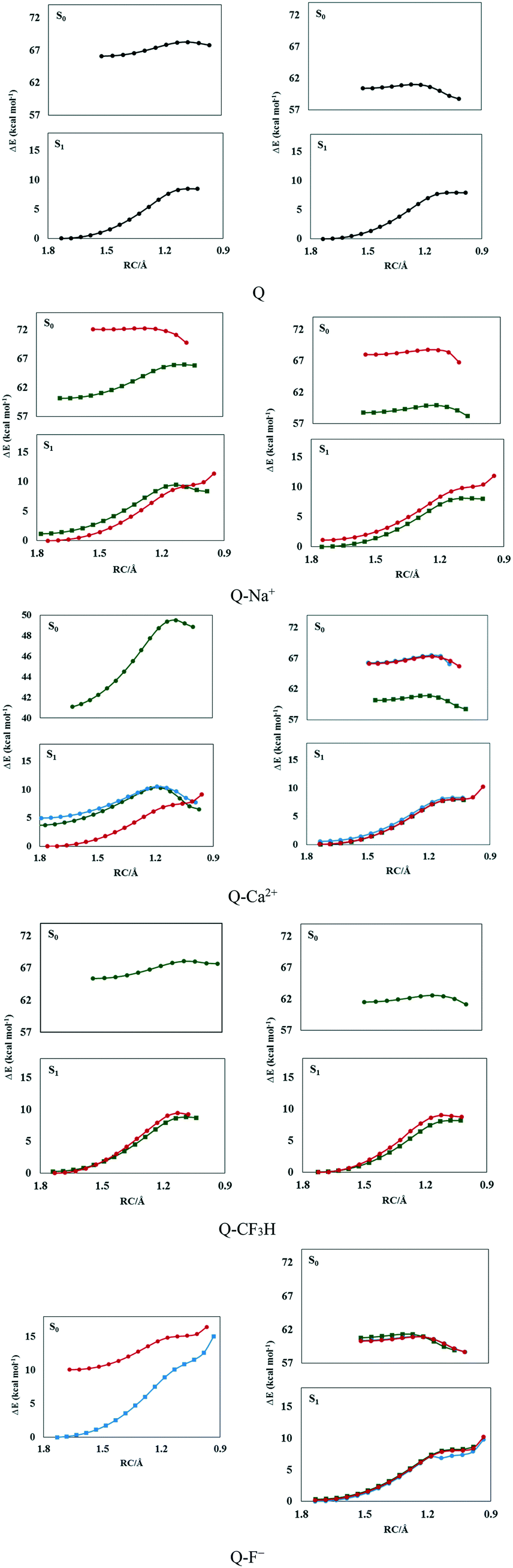 | ||
| Fig. 1 The potential energy curves of the S0 and S1 states in the gas phase (left panel) and solution (right panel) calculated at the M06-2X/6-311++G(d,p) level. The green, blue, and red curves correspond to the complex types a, b, and c, respectively. | ||
As seen in Fig. 1, complexes of type a were more stable than the others; the electrostatic, polarization, dispersion, charge transfer, and induction forces are the main components of ion–π interactions. The π-electron cloud is affected by electron-withdrawing carbonyl groups in ring b and the two intramolecular hydrogen bonds between rings b and c via the reduction of the negative charge of the π-electron clouds of rings b and c. This reduces the electrostatic energy component in the ion–π interactions in the complexes of type b and c but not the complexes of type a; thus, complexes of type a are more stable than the other types.
As seen in Fig. 1, the normal form (N) was more stable than the tautomer obtained from proton transfer (T) in the ground states. The high energy barrier of N → T transformation (6–9 kcal mol−1) and the instability of T make the proton transfer process unfavorable in the S0 state in the gas phase.
The potential energy curves indicated that the proton transfer energy barrier decreased with complexation. Moreover, the energy barrier of the reverse process increased in the cationic complexes. Therefore, proton transfer was facilitated by the cation–π interactions in the ground state. The highest change in the proton transfer process was observed in the presence of Mg2+ and Ca2+ ions owing to the lowest energy barriers (6.09 and 6.63 kcal mol−1) and the highest reverse barriers (4.62 and 3.77 kcal mol−1). As seen in Fig. 1, the energy barriers were lower in the S1 state, which testifies that the proton transfer process preferably occurred in the S1 state. However, no barrier was observed for the reverse process in the S1 state in the gas phase, which shows the instability of the T form.
The high energy barriers (7–9 kcal mol−1) make the ground state proton transfer a relatively difficult process in the ground state in solution, in which the process is endothermic. However, almost no barrier (0.004–0.20 kcal mol−1) was observed for the reverse process in the ground state. The N form could easily be transferred to T by crossing a low potential barrier after photoexcitation. According to the potential curves shown in Fig. 1, the potential energy barriers were in the range of 0.5–1.5 kcal mol−1 in the S1 state, where the lowest value corresponded to the Q–F− complex, in which proton transfer did not occur in the S0 state. Moreover, the T form was more stable than N in the S1 state in solution, rendering ESIPT an exothermic process. Therefore, the N–T isomerization of the complexes in solution could be attributed to proton transfer in the excited state and the reverse process in the ground state. The solvent affects the electronic charge distribution of the system due to electrostatic interactions with the solute. Moreover, shorter-range non-electrostatic effects, such as cavitation, dispersion, and solvent structural effects, are taken into account for reliable calculations of solutes in solution, especially in the presence of strong hydrogen bonding in the system. These lead to the stability of the whole system and the enhancement of intramolecular hydrogen bonds in solution, which facilitates the ESIPT process.
The potential energy curves were also calculated with dimethyl sulfoxide (DMSO) as the solvent and are depicted in Fig. S2.† Because of the aprotic and polarizable properties, its chemical nature is very different from water.82 However, like water, it has a high dielectric constant (ε = 46). According to Fig. S2,† ground-state proton transfer was not possible in DMSO (Fig. S2†) since a low energy barrier is required for the ESIPT process; these values were in the range of 0.30–1.50 kcal mol−1, and the lowest value corresponded to the Q–Na+ complex. The ESIPT process occurred in the cationic complexes with lower barriers than those of the anionic complexes.
In addition, water molecules were explicitly considered in the calculations. During optimization, the ions were surrounded by water molecules, as shown in Fig. 2 and S3.†
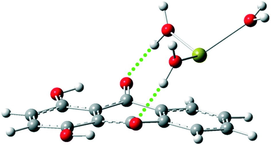 | ||
| Fig. 2 The optimized structure of the Q–Ca2+ complex in the presence of explicit water molecules, as calculated at the M06-2X/6-311++G(d,p) level. | ||
The intermolecular hydrogen bond interactions were observed between the carbonyl groups of Q and the water molecules. Therefore, it is difficult for proton transfer to occur in the presence of water molecules. The calculated potential energy curves for some complexes are shown in Fig. S4.† The process did not occur in complexes containing monovalent ions in the S0 and S1 states. High potential barriers (up to 7 kcal mol−1) were observed for proton transfer in complexes containing divalent cations in the S0 state, while the process did not occur in the S1 state of these complexes. The hydrogen bond interactions between the carbonyl groups and water molecules are strengthened in the excited state, which can affect the ESIPT process. It seems that the effect of ion–π interactions on the ESIPT process is perturbed by the presence of explicit water molecules.
Excitation and emission energies
Compounds, in general, are initially photoexcited from the S0-N state to the S1-Franck–Condon (S1-FC) state and then are relaxed to the minimum S1 state (S1-N). The S1-N state transitions back to the ground state via fluorescence emission or participates in the ESIPT reaction to form T in the first excited state (S1-T). Then, S1-T returns to the ground state via radiative transition. Finally, S0-T quickly regresses to form the S0-N isomer by the reverse proton transfer process.The excitation and fluorescent energies for the S0-N, S1-N, and S1-T forms and corresponding oscillator strengths are listed in Table 4, and the electronic spectra of the complexes are shown in Fig. 3 and S5.†
| S0-N | S1-N | S1-T | |||||||
|---|---|---|---|---|---|---|---|---|---|
| λ (nm) | E (eV) | f | λ (nm) | E (eV) | f | λ (nm) | E (eV) | f | |
| The data in parentheses are calculated in solution. | |||||||||
| a | |||||||||
| Q | 390.83 (392.10) | 3.17 (3.16) | 0.208 (0.271) | 481.87 (548.05) | 2.57 (2.26) | 0.211 (0.434) | 521.59 (630.38) | 2.38 (1.97) | 0.269 (0.511) |
| Q–Na+ | 435.33 (401.46) | 2.85 (3.09) | 0.195 (0.257) | 541.32 (561.27) | 2.29 (2.21) | 0.187 (0.409) | 540.35 (637.43) | 2.29 (1.95) | 0.267 (0.493) |
| Q–K+ | 426.96 (401.81) | 2.90 (3.09) | 0.199 (0.259) | 529.90 (562.62) | 2.34 (2.20) | 0.192 (0.411) | 536.34 (636.94) | 2.31 (1.95) | 0.268 (0.493) |
| Q–Mg2+ | (406.51) | (3.05) | (0.255) | (570.87) | (2.17) | (0.407) | (645.14) | (1.92) | (0.497) |
| Q–Ca2+ | 617.05 (394.46) | 2.01 (3.14) | 0.119 (0.270) | 868.40 (550.36) | 1.43 (2.25) | 0.068 (0.432) | 993.25 (631.79) | 1.25 (1.96) | 0.003 (0.509) |
| Q–F− | (392.02) | (3.16) | (0.273) | (547.74) | (2.26) | (0.434) | (631.55) | (1.96) | (0.512) |
| Q–CF3H | 396.47 (395.97) | 3.13 (3.13) | 0.205 (0.256) | 489.26 (530.54) | 2.53 (2.34) | 0.206 (0.382) | 525.38 (598.05) | 2.36 (2.07) | 0.267 (0.460) |
| b | |||||||||
| Q–Mg2+ | (393.93) | (3.15) | (0.270) | (494.01) | (2.51) | (0.287) | (550.91) | (2.25) | (0.348) |
| Q–Ca2+ | (393.81) | (3.15) | (0.270) | (494.08) | (2.51) | (0.288) | (550.90) | (2.25) | (0.349) |
| Q–F− | (389.24) | (3.19) | (0.261) | (547.99) | (2.26) | (0.432) | (630.67) | (1.97) | (0.509) |
| Q–Cl− | (389.24) | (3.19) | (0.238) | (604.97) | (2.05) | (0.292) | (669.66) | (1.85) | (0.429) |
| c | |||||||||
| Q–Na+ | 370.88 (372.65) | 3.34 (3.33) | 0.002 (0.263) | 449.43 (492.45) | 2.76 (2.52) | 0.207 (0.287) | 529.80 (561.81) | 2.34 (2.21) | 0.259 (0.346) |
| Q–K+ | 369.28 (375.72) | 3.36 (3.30) | 0.005 (0.259) | 451.59 (492.32) | 2.75 (2.52) | 0.207 (0.287) | 504.36 (558.82) | 2.46 (2.22) | 0.239 (0.348) |
| Q–Mg2+ | (390.34) | (3.18) | (0.269) | (547.20) | (2.27) | (0.433) | (632.21) | (1.96) | (0.508) |
| Q–Ca2+ | (390.93) | (3.17) | (0.268) | (492.04) | (2.52) | (0.286) | (550.47) | (2.25) | (0.348) |
| Q–F− | (393.94) | (3.15) | (0.265) | (550.52) | (2.25) | (0.432) | (632.71) | (1.96) | (0.508) |
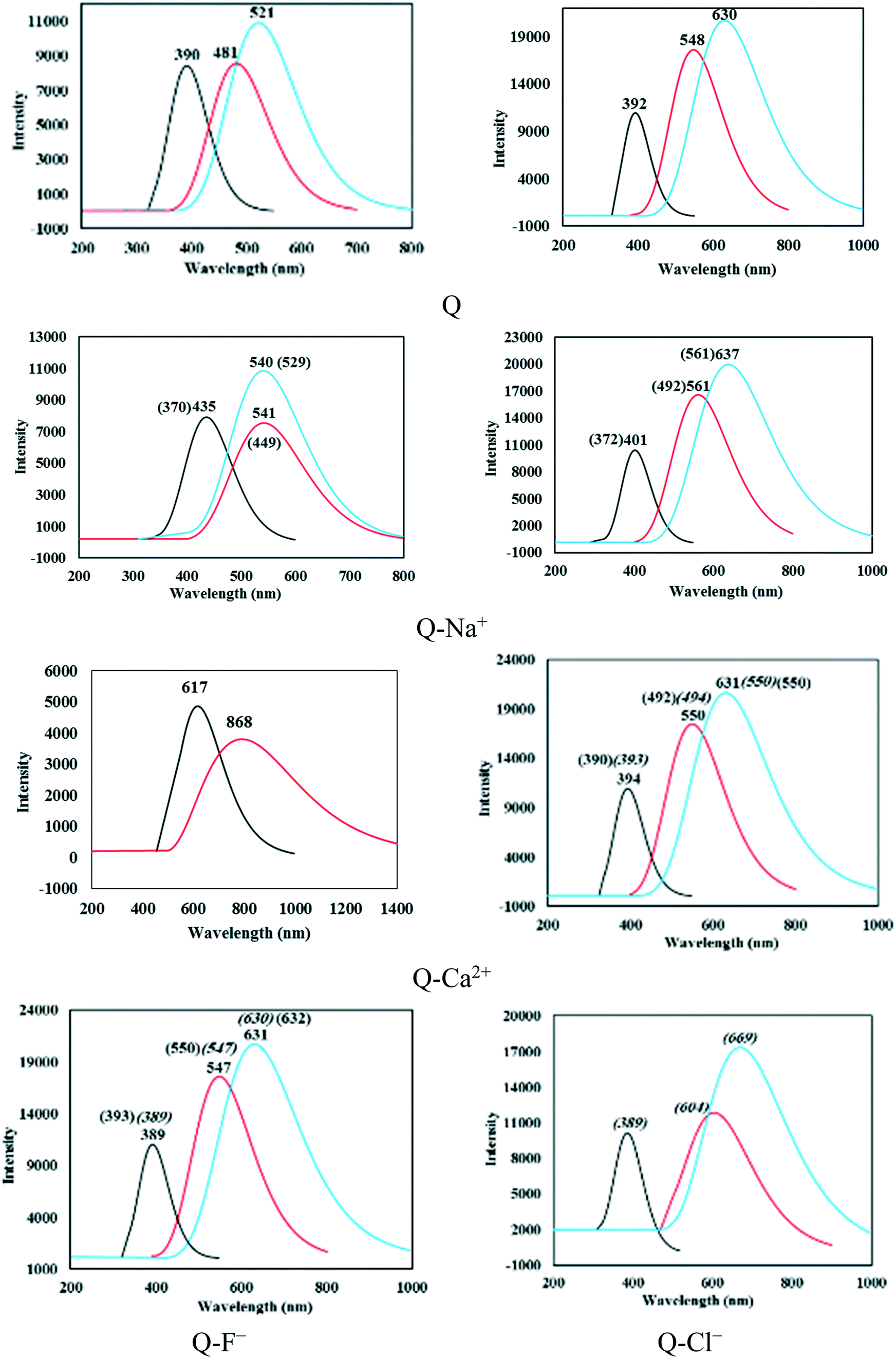 | ||
| Fig. 3 The absorption and fluorescence spectra calculated at the TDDFT/M06-2X/6-311++G(d,p) theoretical level. The black, red, and blue lines represent absorption and the S1-N, and S1-T fluorescence emission, respectively. The italicized values and those in parenthesis correspond to the complexes of types b and c, respectively. | ||
The S0–S1 vertical excitation energy (VEE) and electronic spectra were calculated using the optimized ground- and excited-state geometries as the initial configurations. An absorption band of Q was located at 390.83 nm (3.17 eV) in the spectrum of the gas phase and at 392.10 nm (3.16 eV) in that of solution. A red or blue shift was observed for this band with the cation–π, anion–π, and CH–π interactions. As seen in Table 4, the largest redshift corresponded to the complexes of type a. The wavelengths (λ values) calculated in the gas phase (and in solution) for the Q–Na+, Q–K+, Q–Mg2+, Q–Ca2+, Q–F−, and Q–CF3H complexes of type a were respectively equal to 435.33 (401.46), 426.96 (401.81), (406.51), 617.05 (394.46), (392.02), and 396.47 (395.97) nm. Obviously, all complexes of this type showed a redshift after complexation, with the exception of Q–F−, which exhibited a small blue shift (0.08 nm). The maximum redshift corresponded to the Q–Ca2+ and Q–Mg2+ complexes in the gas phase and solution, respectively. The VEE values of the mentioned complexes were respectively equal to 2.85 (3.09), 2.90 (3.09), (3.05), 2.00 (3.14), (3.16), and 3.13 (3.13) eV in the gas phase (and solution). The lowest VEEs corresponded to the Q–Ca2+ and Q–Mg2+ complexes that showed the largest redshift values, and the highest value corresponded to the Q–F− complex that showed a small blueshift of the mentioned absorption band.
According to Table 4, the cationic (anionic) complexes of type b, including Q–Mg2+ and Q–Ca2+ (Q–F−, and Q–Cl−), show small red (blue)-shifts of 1.83 and 1.71 (2.86, and 2.86) nm, respectively. A small redshift of 1.84 nm was observed for Q–F−, while blueshifts of 19.95 (19.45), 21.55 (16.38), (1.76), and (1.17) nm were respectively observed for the Q–Na+, Q–K+, Q–Mg2+, Q–Ca2+ complexes of type c in the gas phase (solution). Hence, the largest red- and blueshifts were observed for the complexes of types a and c, respectively.
The intensities of the absorption bands were related to the oscillator strengths (f) given in Table 4. The calculated f values indicated the following trend for the complexes of type a:
| Q–Ca2+ < Q–Na+ < Q–K+ < Q–CF3H < Q in the gas phase |
| Q–Mg2+ < Q–CF3H < Q–Na+ < Q–K+ < Q–F− < Q–Ca2+ < Q in solution |
In all complexes, S1-N could return to the ground state via the fluorescence emission. The wavelengths of the S1-N fluorescence emissions calculated based on the optimized excited states of the N forms are reported in Table 4. The S1-N emission wavelengths were longer in solution compared with those in the gas phase; the longest values corresponded to Q–Cl−-b and Q–Ca2+-a in the solution and gas phase, respectively. The S1-N emission bands of Q were located at 481.87 and 548.05 nm in the gas phase and solution, respectively. Blueshifts of 0.31 and 17.51 nm were observed for the emission bands of the Q–F−-a and Q–CF3H-a complexes in solution, while the band showed redshift after complexation with a cation. According to Table 4, the longest emission wavelengths (and the lowest emission energies) corresponded to the complexes of divalent cations, Q–Mg2+ and Q–Ca2+. Moreover, all complexes exhibited redshifted S1-N emission wavelengths relative to their vertical excitation wavelengths, which could be ascribed as the Stokes shift. The Stokes shift for the S1-N emission bands of Q and the Q–Na+, Q–K+, Q–Mg2+, Q–Ca2+, Q–F−, and Q–CF3H complexes of type a were respectively 91.04 (155.95), 105.99 (159.81), 102.94 (160.81), (164.36), 251.35 (155.90), (155.72), and 92.79 (134.57) nm in the gas phase (and solution). The complexes showed normal Stokes shifts in the gas phase and large Stokes shifts in solution.
The S1-N state is transformed into S1-T under the ESIPT process and then converts to S0-T via radiative transition. The calculated S1-T fluorescence emission wavelengths are also reported in Table 4. The wavelengths of Q and the Q–Na+, Q–K+, Q–Mg2+, Q–Ca2+, Q–F−, and Q–CF3H complexes of type a were respectively equal to 521.59 (630.38), 540.35 (637.43), 536.34 (636.94), (654.14), (631.79), (631.55), and 525.38 (598.05) nm in the gas phase (solution). Thus, the S1-T fluorescence emissions of the complexes of type a were in the range of 521–654 nm. The S1-T emission band of Q–Ca2+ was located at a large wavelength, 993.25 nm, with an intensity close to zero (Table 4). It was concluded that Q–Ca2+ had no emission peak from S1-T. Therefore, single fluorescence emission was observed for this complex (Fig. 3).
The related wavelengths for the complexes of types b and c were in the ranges of 550–700 and 504–632 nm, respectively. A redshift in the fluorescence emission was observed with complexation in complexes of type a; the Q–Mg2+ complex showed the largest redshift in both phases. The S1-T emission of Q–CF3H displayed a small redshift of 3.79 nm in the gas phase, and a blueshift of 32.33 nm in solution. Unlike the cationic complexes, the anionic complexes of type b showed a redshift of S1-T emission. As seen in Table 4, the complexes of type c, namely Q–Mg2+ and Q–F− in solution and Q–Na+ in the gas phase, showed redshifts of 1.83, 2.33, and 8.21 nm, respectively. The blueshift values for the Q–Na+, Q–K+, and Q–Ca2+ complexes were respectively 68.57, 71.56, and 79.91 nm in solution.
According to the f values reported in Table 4, the intensities of S1-T fluorescence emission bands were higher than those of S1-N in both phases. The trend of the intensities of S1-T emission bands for the complexes of type a was:
| Q–Ca2+ < Q–CF3H < Q–Na+ < Q–K+ < Q in the gas phase |
| Q–CF3H < Q–Na+ < Q–K+ < Q–Mg2+ < Q–Ca2+ < Q < Q–F− in solution, |
According to the absorption and S1-T emission bands given in Table 4 and Fig. 3, all compounds demonstrated large Stokes shifts, which were equal to 130.76 (238.28), 105.02 (235.97), 109.38 (235.13), (238.63), (237.33), (239.53), and 128.91 (202.08) nm for Q and the Q–Na+, Q–K+, Q–Mg2+, Q–Ca2+, Q–F−, and Q–CF3H complexes of type a, respectively, in the gas phase (solution). The Stokes shifts in solution were larger than those in the gas phase. The largest Stokes shift in solution was observed for the Q–F− complex (see Fig. 3).
The Stokes shift values of the Q–Mg2+, Q–Ca2+, Q–F−, and Q–Cl− complexes of type b were respectively 156.98, 157.09, 241.43, and 280.42 nm. The Stokes shifts were 158.92 (189.16), 135.08 (183.10), (241.87), (159.54), and (238.77) nm for the Q–Na+, Q–K+, Q–Mg2+, Q–Ca2+, Q–F− complexes of type c in the gas phase (solution), respectively. The largest value corresponded to the Q–Cl− complex in solution (Fig. 3). A large Stokes shift suggests that the structural geometry of the emissive excited state is significantly different from that of the ground state. Therefore, the large Stokes shift indicated major structural and electronic configuration changes upon photoexcitation of the compounds. According to Tables 2, S1, and S2,† the changes in the important geometrical parameters were greater in solution than those in the gas phase for all three types of complexes, especially the anionic complexes. Hence, it is logical to observe the largest Stokes shifts for anionic complexes in solution. A large Stokes shift is a favorable property for fluorescent compounds,24 which can be applied in high-energy radiation detectors.6 Therefore, complex formation reinforces the fluorescence nature of Q, especially in solution.
The fluorescence rate constants, kf, calculated for the S1-N and S1-T forms via Einstein's emission transition probability equation:83,84
| kf = f × ν(cm−1)/1.5 | (1) |
| S1-N | S1-T | |||
|---|---|---|---|---|
| k f (S−1)/106 | τ f/ns | k f (S−1)/106 | τ f/ns | |
| The data in parenthesis are calculated in solution. | ||||
| a | ||||
| Q | 60.55 (96.42) | 16.51 (10.37) | 65.94 (85.69) | 15.16 (11.67) |
| Q–Na+ | 42.48 (86.51) | 23.54 (11.56) | 61.05 (80.87) | 16.38 (12.37) |
| Q–K+ | 45.54 (86.54) | 21.96 (11.56) | 62.18 (81.01) | 16.08 (12.34) |
| Q–Mg2+ | (83.20) | (12.02) | (79.62) | (12.56) |
| Q–Ca2+ | 5.98 (95.13) | 167.33 (10.51) | (85.01) | (11.76) |
| Q–F− | (96.46) | (10.37) | (85.51) | (11.69) |
| Q–CF3H | 57.48 (90.57) | 17.40 (11.04) | 64.54 (85.70) | 15.50 (11.67) |
| b | ||||
| Q–Mg2+ | (78.37) | (12.76) | (76.40) | (13.09) |
| Q–Ca2+ | (78.60) | (12.72) | (76.64) | (13.05) |
| Q–F− | (96.00) | (10.42) | (85.33) | (11.72) |
| Q–Cl− | (53.15) | (18.81) | (63.72) | (15.69) |
| c | ||||
| Q–Na+ | 68.19 (78.98) | 14.67 (12.66) | 61.49 (73.04) | 16.26 (13.69) |
| Q–K+ | 67.57 (79.05) | 14.80 (12.65) | 62.69 (74.23) | 15.95 (13.47) |
| Q–Mg2+ | (96.29) | (10.38) | (84.80) | (11.79) |
| Q–Ca2+ | (78.86) | (12.68) | (76.50) | (13.07) |
| Q–F− | (94.98) | (10.53) | (84.67) | (11.81) |
The radiation lifetimes (τ = 1/kf) of the S1-N and S1-T states are also given in Table 5. The longest radiation lifetime is respectively corresponded to the S1-N emission of Q–Ca2+-a and the S1-T emission of Q–Na+-c, in the gas and solution phases. The trend of the radiation lifetimes of S1-T emission for the complexes of type a in the gas phase and solution was:
| Q < Q–CF3H < Q–K+ < Q–Na+ in the gas phase |
| Q–CF3H < Q < Q–F− < Q–K+ < Q–Na+ < Q–Mg2+ < Q–Ca2+ in solution |
Vibrational spectra
The ground- and excited-state infrared vibrational frequencies of the complexes were calculated, and the spectral regions of the O–H stretching band are shown in Fig. 4. The changes in the S1 state hydrogen bond can be confirmed via the detection of an IR vibrational spectral shift.85 The O–H bond stretching vibrational frequency for Q was located at 3502.46 (3480.13) cm−1 in the S0 state and 2817.73 (2598.33) cm−1 in the S1 state in the gas phase (solution). Hence, it undergoes a large redshift of 684.73 (881.80) cm−1 during the S0 → S1 transition, which is in agreement with stronger IHB in the S1 state. Similarly, large redshifts were observed upon excitation of the π complexes, which were considerably larger in solution compared with those in the gas phase.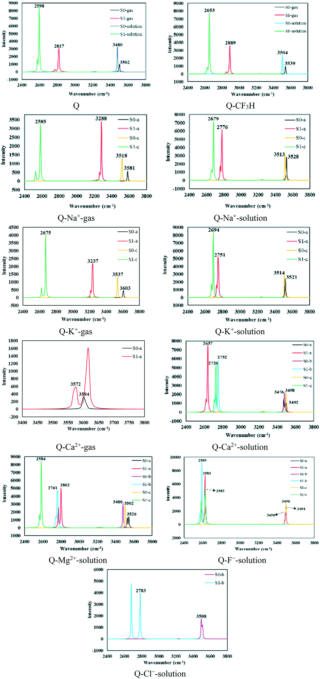 | ||
| Fig. 4 The infrared vibrational spectra of the O–H bond in the S0 and S1 states calculated using the M06-2X/6-311++G(d,p) level. | ||
The O–H bond stretching vibrational frequencies and redshift values are reported in Table 6. The redshift values for the Q–Na+, Q–K+, Q–Mg2+, Q–Ca2+, Q–F−, and Q–CF3H complexes of type a were respectively 298.14 (751.63), 366.57 (770.57), (724.10), 22.26 (855.59), (911.23), and 650.08 (850.76) cm−1 in the gas phase (solution). As seen in Table 6, the Q–Na+-c and Q–Mg2+-c complexes showed the largest redshifts of 933.03 and 917.99 cm−1 in the gas phase and solution, respectively. In addition, the stretching vibrational frequency of the O–H bond in all types of Q–F− complexes showed redshifts larger than 900 cm−1. The strengthened IHBs in the S1 state facilitate the ESIPT process; the process occurs with the low potential barriers of 0.54, 0.58, and 0.61 kcal mol−1 in the Q–F−-a, Q–F−-b, and Q–F−-c complexes, respectively (see Fig. 1). F− is a strongly nucleophilic anion, and a large amount of charge transfer occurs from the anion to the π system, especially in the excited state, which enhances the resonance effect of Q and results in the reinforcement of IHBs in these complexes.
| ν (cm−1) | |||
|---|---|---|---|
| S0 | S1 | Redshift | |
| The data in parentheses are calculated in solution. | |||
| a | |||
| Q | 3502.46 (3480.13) | 2817.73 (2598.33) | 684.73 (881.80) |
| Q–Na+ | 3581.71 (3528.29) | 3288.81 (2776.66) | 292.90 (751.63) |
| Q–K+ | 3603.74 (3521.94) | 3237.17 (2751.37) | 366.57 (770.57) |
| Q–Mg2+ | (3526.37) | (2802.27) | (724.10) |
| Q–Ca2+ | 3594.65 (3492.64) | 3572.39 (2637.05) | 22.26 (855.59) |
| Q–F− | (3494.47) | (2583.24) | (911.23) |
| Q–CF3H | 3539.66 (3504.02) | 2889.58 (2653.26) | 650.08 (850.76) |
| b | |||
| Q–Mg2+ | (3480.09) | (2761.43) | (718.66) |
| Q–Ca2+ | (3476.46) | (2752.91) | (723.55) |
| Q–F− | (3490.89) | (2589.96) | (900.93) |
| Q–cl− | (3508.97) | (2783.71) | (725.26) |
| c | |||
| Q–Na+ | 3518.31 (3513.76) | 2585.28 (2679.47) | 933.03 (834.29) |
| Q–K+ | 3537.65 (3514.24) | 2675.29 (2694.89) | 862.36 (819.35) |
| Q–Mg2+ | (3502.40) | (2584.41) | (917.99) |
| Q–Ca2+ | (3498.37) | (2726.86) | (771.51) |
| Q–F− | (3496.00) | (2583.25) | (912.75) |
As seen in Fig. 5, a good linear relationship (R2 = 0.96) was observed between the redshifts of the O–H bond stretching vibrational frequencies and the energy barriers for the ESIPT process.
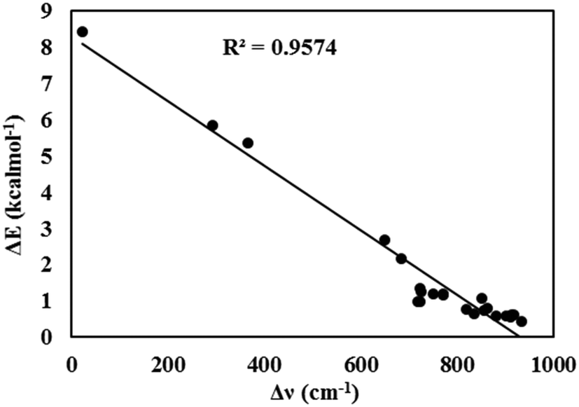 | ||
| Fig. 5 The linear relationship between the redshifts of the O–H bond stretching vibration frequencies and the energy barriers for the ESIPT process. | ||
The frontier molecular orbital analysis
The charge distribution and charge transfer properties during the ESIPT process were explored based on the analysis of the frontier molecular orbitals (FMOs).The highest occupied molecular orbital (HOMO) and the lowest unoccupied molecular orbital (LUMO) of some complexes are shown in Fig. 6. Mainly, the first excited state includes these orbitals.86
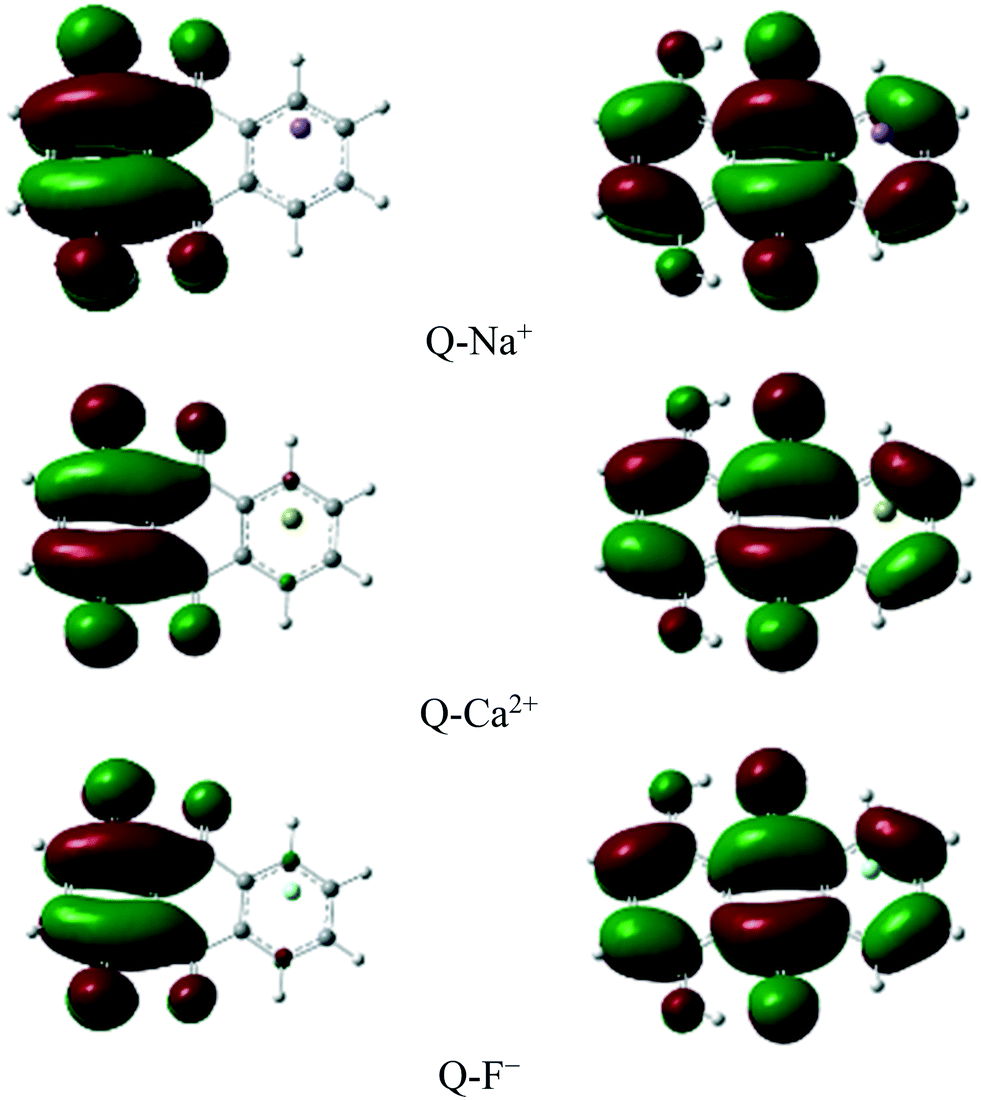 | ||
| Fig. 6 HOMOs (left panel) and LUMOs (right panel) of some complexes. | ||
The results showed that the vertical transition in the Frank–Condon region of the complexes corresponded to the excitation from HOMO (π) to LUMO (π*). The excitation wavelengths, orbital contributions, and oscillator strengths are summarized in Table 7. A strong transition of S0 → S1 is predicted in Q at 390.83 nm with an oscillator strength of 0.208, and the HOMO–LUMO contribution is predicted to be 70%. As seen in Table 7, the lowest transition in the Frank–Condon region corresponded to HOMO → LUMO with large contributions in the range of 69.97 to 70.66% in all the complexes.
| Transition | λ (nm) | f | Orbital contributions (%) | |
|---|---|---|---|---|
| The data in parenthesis calculated in the solution media. | ||||
| Q | S0 → S1 | 390.83 (392.10) | 0.208 (0.271) | H → L 70.00 (70.04) |
| S0 → S2 | 298.89 (309.28) | 0.000 (0.001) | H−1 → L 63.84 (66.43) | |
| S0 → S3 | 276.87 (288.21) | 0.058 (0.088) | H−2 → L 66.34 (67.76) | |
| Q–Na+ | S0 → S1 | 435.33 (401.46) | 0.195 (0.257) | H → L 70.35 (70.06) |
| S0 → S2 | 295.77 (301.65) | 0.031 (0.006) | H−1 → L 64.66 (62.56) | |
| S0 → S3 | 367.62 (269.52) | 0.000 (0.075) | H−2 → L 64.07 (66.01) | |
| Q–K+ | S0 → S1 | 426.96 (401.81) | 0.200 (0.259) | H → L 70.29 (70.05) |
| S0 → S2 | 292.51 (302.69) | 0.024 (0.005) | H−1 → L 62.21 (63.32) | |
| S0 → S3 | 366.36 (271.90) | 0.000 (0.076) | H−2 → L 64.16 (66.37) | |
| Q–Mg2+ | S0 → S1 | (406.51) | (0.255) | H → L (69.97) |
| S0 → S2 | (302.52) | (0.010) | H−1 → L (53.11) | |
| S0 → S3 | (270.20) | (0.093) | H−2 → L (65.80) | |
| Q–Ca2+ | S0 → S1 | 617.05 (394.46) | 0.119 (0.270) | H → L 70.66 (70.05) |
| S0 → S2 | 359.43 (308.89) | 0.020 (0.000) | H−1 → L 65.52 (66.36) | |
| S0 → S3 | 403.05 (286.55) | 0.000 (0.086) | H−2 → L 61.72 (67.62) | |
| Q–F− | S0 → S1 | (392.02) | (0.273) | H → L (70.03) |
| S0 → S2 | (310.52) | (0.002) | H−1 → L (65.83) | |
| S0 → S3 | (290.46) | (0.084) | H−2 → L (67.57) | |
| Q–CF3H | S0 → S1 | 396.47 (395.97) | 0.205 (0.256) | H → L 70.10 (70.07) |
| S0 → S2 | 297.36 (302.61) | 0.001 (0.000) | H−1 → L 60.33 (65.40) | |
| S0 → S3 | 269.52 (279.51) | 0.051 (0.077) | H−2 → L 65.68 (67.17) | |
The S0 → S2 and S3 transitions, which involve HOMO−1 → LUMO and HOMO−2 → LUMO, were also allowed. Despite large orbital contributions, their oscillator strengths were in the range of 0.000 to 0.097. Therefore, it is predicted that S0 → S1 is the only observed transition in these complexes.
Conclusions
The effect of cation–π, anion–π, and CH–π interactions on the photophysical properties and the excited-state proton transfer (ESIPT) mechanism of quinizarin have been studied using DFT and TD-DFT at the M06-2X/6-311++G(d,p) level in the gas phase and solution. The proton transfer process is associated with the formation of a six-membered hydrogen-bonded ring in the structures. The high potential barrier of the N (normal form) to T (tautomer) conversion and the instability of T make the process unfavorable in the ground state. The cation–π interaction facilitates the process in the S0 state; the divalent cations are more effective.The S0 → S1 excitation makes the intramolecular hydrogen bond stronger, which facilitates the proton transfer process in the first excited state. The energy barrier of N → T conversion generally decreases in the gas phase. However, the low reverse energy barrier and the better stability of N in comparison with T make the excited-state proton transfer an unfavorable process in the gas phase. In water and DMSO, the potential energy barrier of the N → T process is low in the S1 state, and T is more stable than N; therefore, the excited state proton transfer is an exothermic process in these media. Moreover, the O–H bond stretching vibrational frequencies in the complexes were in good agreement with the O–H bond lengths. Large redshifts of the O–H bond stretching vibrational frequencies were observed upon excitation of the π-complexes, which are in agreement with stronger IHB in the S1 state. This was considerably larger in solution compared with that in the gas phase. The results showed a good linear relationship (R2 = 0.96) between the redshifts of the O–H bond stretching vibrational frequencies and the energy barriers for the ESIPT process.
The cation–π, anion–π, and CH–π interactions changed the absorption and emission bands of quinizarin. A red- or blueshift of the absorption band was seen with the cation–π, anion–π, and CH–π interactions. The absorption wavelengths were in the range of 369–617 and 389–406 nm in the gas phase and solution, respectively. Both S1-N and S1-T fluorescence emissions were observed for most of the complexes. The intensities of the S1-T fluorescence emission bands were higher than those of S1-N in both phases. The longest emission wavelengths (and the lowest emission energies) corresponded to the complexes of divalent cations. The ranges of the S1-N and S1-T fluorescence emissions were respectively 449–868 and 504–628 nm in the gas phase. The ranges changed to 492–604 and 550–669 nm in solution. Hence, a wide tunable range is available for fluorescence emission. The fluorescent rate constants were greater in solution than those in the gas phase, and the longest radiation lifetime corresponded to the cationic complexes in both phases.
The large Stokes shifts of the complexes, which were larger in solution, indicate their desirable fluorescence properties. The anionic complexes possessed the largest Stokes shifts in solution. This indicates major structural and electronic configuration changes upon photoexcitation occurring from HOMO (π) to LUMO (π*). Despite the large orbital contributions of the S0 → S2 and S3 transitions, their small oscillator strengths demonstrate that the S0 → S1 is the only observed transition in these complexes.
In summary, an improvement in the optical and photophysical properties of quinizarin is observed because of the ion–π interactions in different positions of the compound due to its capability to take part in these interactions. This can be further developed for such compounds to achieve wider use in fields, such as LEDs, molecular switches and fluorescence imaging.
Conflicts of interest
There are no conflicts to declare.Acknowledgements
We thank University of Sistan and Baluchestan for financial support and Computational Quantum Chemistry Laboratory for providing computational facilities.References
- S. Sinha, B. Chowdhury and P. Ghosh, Inorg. Chem., 2016, 55, 9212 CrossRef CAS.
- S. B. Roy, A. Maity and K. K. Rajak, Inorg. Chem. Commun., 2017, 76, 81 CrossRef CAS.
- X. Jin, C. Liu, X. Wang, H. Huang, X. Zhang and H. Zhu, Sens. Actuators, B, 2015, 216, 141 CrossRef CAS.
- K. I. Sakai, M. Ichikawa and Y. Taniguchi, Chem. Phys. Lett., 2006, 420, 405 CrossRef CAS.
- K. I. Sakai, T. Tsuzuki, Y. Itoh, M. Ichikawa and Y. Taniguchi, Appl. Phys. Lett., 2005, 86, 081103 CrossRef.
- P. T. Chou and M. L. Martinez, Radiat. Phys. Chem., 1993, 41, 373 CrossRef CAS.
- C. Chudoba, E. Riedle, M. Pfeiffer and T. Elsaesser, Chem. Phys. Lett., 1996, 263, 622 CrossRef CAS.
- J. Seo, S. Kim and S. Y. Park, J. Am. Chem. Soc., 2004, 126, 11154 CrossRef CAS.
- J. Zhao, S. Ji, Y. Chen, H. Guo and P. Yang, Phys. Chem. Chem. Phys., 2012, 14, 8803 RSC.
- Y. Wang, M. Zhu, E. Jiang, R. Hua, N. Risong and X. L. Qing, Sci. Rep., 2017, 7, 1 CrossRef.
- S. Park, E. K. Ji, S. H. Kim, J. Seo, K. Chung, S. Y. Park, D. J. Jang, B. M. Medina, J. Gierschner and S. Y. Park, J. Am. Chem. Soc., 2009, 131, 14043 CrossRef CAS.
- A. Weller, Z. Elektrochem., 1956, 60, 1144 CAS.
- L. G. Arnaut and S. J. Formosinho, J. Photochem. Photobiol., A, 1993, 75, 1 CrossRef CAS.
- N. Agmon, J. Phys. Chem. A, 2005, 109, 13 CrossRef CAS.
- J. E. Kwon and S. Y. Park, Adv. Mater., 2011, 23, 3615 CrossRef CAS.
- N. Suzuki, A. Fukazawa, K. Nagura, S. Saito, H. Kitoh-Nishioka, D. Yokogawa, S. Irle and S. Yamaguchi, Angew. Chem., Int. Ed., 2014, 53, 8231 CrossRef CAS.
- P. Zhou and K. Han, Acc. Chem. Res., 2018, 51, 1681 CrossRef CAS.
- J. D. Huang, J. B. Zhang, D. Y. Chen and H. P. Ma, Org. Chem. Front., 2017, 4, 1812 RSC.
- D. P. Yang, J. F. Zhao, G. Yang, N. H. Song, R. Zheng and Y. S. Wang, Org. Chem. Front., 2017, 4, 1935 RSC.
- G. J. Zhao and K. L. Han, J. Phys. Chem. A, 2009, 113, 14329 CrossRef CAS.
- T. Mutai, T. Ohkawa, H. Shono and K. Araki, J. Mater. Chem. C, 2016, 4, 3599 RSC.
- F. S. Santos, E. Ramasamy, V. Ramamurthy and F. S. Rodembusch, J. Photochem. Photobiol., A, 2016, 317, 175 CrossRef CAS.
- R. Ali, S. M. Saleh and R. F. M. Elshaarawy, RSC Adv., 2016, 6, 86965 RSC.
- M. Arribat, E. Remond, S. C. Ment, A. V. D. Lee and F. Cavelier, J. Am. Chem. Soc., 2018, 140, 1028 CrossRef CAS.
- S. Bhuiya, L. Haque, R. Goswami and S. Das, J. Phys. Chem. B, 2017, 121, 11037 CrossRef CAS.
- S. Shendre, V. K. Sharma, C. Dang and H. V. Demir, ACS Photonics, 2018, 5, 480 CrossRef CAS.
- L. Stricker, E. C. Fritz, M. Peterlechner, N. L. Doltsinis and B. J. Ravoo, J. Am. Chem. Soc., 2016, 138, 4547 CrossRef CAS.
- C. Yin, X. Zhen, H. Zhao, Y. Tang, Y. Ji, Y. Lyu, Q. L. Fan, W. Huan and K. Y. Pu, ACS Appl. Mater. Interfaces, 2017, 9, 12332 CrossRef CAS.
- M. Yanzhen, Y. Yang, R. Lan and Y. Li, J. Phys. Chem. C, 2017, 121, 14779 CrossRef.
- P. Yajing, Y. Ye, X. Xiu and S. Sun, J. Phys. Chem. A, 2017, 121, 5625 CrossRef.
- B. Vijay, A. Kumar and H. Pal, J. Photochem. Photobiol., A, 2018, 350, 111 CrossRef.
- L. Sebok, J. Lee and Y. Pang, Curr. Appl. Phys., 2015, 15, 1492 CrossRef.
- S. J. Schmidtke, D. F. Underwood and D. A. Blank, J. Phys. Chem. A, 2005, 109, 7033 CrossRef CAS.
- M. M. Henary and C. J. Fahrni, J. Phys. Chem. A, 2002, 106, 5210 CrossRef CAS.
- A. Mordzinski and A. Grabowska, Chem. Phys. Lett., 1982, 90, 122 CrossRef CAS.
- Y. Syetov, J. Fluoresc., 2013, 23, 689 CrossRef CAS.
- J. J. Hao and Y. Yang, Org. Chem. Front., 2018, 5, 2234 RSC.
- K. Zhuoran, Q. Guo, X. Wang, H. Song, M. Maroncelli and A. Xia, J. Phys. Chem. Lett., 2018, 9, 4174 CrossRef.
- S. R. Vazquez, M. C. R. Rodriguez, M. Mosquera and F. Rodriguez-Prieto, J. Phys. Chem. A, 2008, 112, 376 CrossRef CAS.
- S. Toshihide, T. Mutai and K. Araki, CrystEngComm, 2013, 15, 10179 RSC.
- M. Quan, D. Sanchez, M. F. Wasylkiw and D. K. Smith, J. Am. Chem. Soc., 2007, 129, 12847 CrossRef CAS.
- P. R. Rich, FEBS Lett., 1981, 130, 173 CrossRef CAS.
- K. Miyazaki, I. Tabata and T. Hori, Color. Technol., 2012, 128, 51 CAS.
- M. W. Rembold and H. E. A. Kramer, J. Soc. Dyers Colour., 1980, 96, 122 CrossRef CAS.
- A. D. Abhayawardhana and T. C. Sutherland, J. Phys. Chem. C, 2009, 113, 4915 CrossRef CAS.
- J. M. Campos-Martin, G. Blanco-Brieva and J. L. G. Fierro, Angew. Chem., Int. Ed., 2006, 45, 6962 CrossRef CAS.
- Q. Huang, G. Lu, H. M. Shen, M. C. M. Chung and N. O. Choon, Med. Res. Rev., 2007, 27, 609 CrossRef CAS.
- Z. C. Xu, J. Y. An, Y. Z. Hu and F. Tian, Chin. Chem. Lett., 2000, 11, 479 CAS.
- A. M. Doi, R. D. Irwin and J. R. Bucher, J. Toxicol. Environ. Health, Part B, 2005, 8, 109 CAS.
- G. Lavie, T. Barliya, M. Mandel, M. Blank, Y. Ron, A. Orenstein, T. Livnat, N. Friedman, L. Weiner, M. Sheves and D. Weinberger, Photochem. Photobiol., 2007, 83, 1270 CrossRef CAS.
- D. K. Palit, H. Pal, T. Mukherjee and J. P. Mittal, J. Chem. Soc., Faraday Trans., 1990, 86, 3861 RSC.
- N. Kandoth, S. Dutta Choudhury, T. Mukherjee and H. Pal, Photochem. Photobiol. Sci., 2009, 8, 82 RSC.
- H. Pal, D. K. Palit, T. Mukherjee and J. P. Mittal, Chem. Phys. Lett., 1990, 173, 354 CrossRef CAS.
- G. Smulevich, P. Foggi, A. Feis and M. P. Marzocchi, J. Chem. Phys., 1987, 87, 5664 CrossRef CAS.
- M. P. Marzocchi, A. R. Mantini, M. Casu and G. Smulevich, J. Chem. Phys., 1998, 108, 534 CrossRef CAS.
- A. Manna, M. Sayed, A. Kumar and H. Pal, J. Phys. Chem. B, 2014, 118, 2487 CrossRef CAS.
- G. Smulevich, J. Chem. Phys., 1985, 82, 14 CrossRef CAS.
- P. Dahiya, M. Kumbhakar, T. Mukherjee and H. Pal, J. Mol. Struct., 2006, 798, 40 CrossRef CAS.
- Y. Ma, Y. Yang, R. Lan and Y. Li, J. Phys. Chem. C, 2017, 121, 14779 CrossRef CAS.
- H. Ulrich, A. Marsell and M. Riederer, J. Agric. Food Chem., 2018, 66, 3393 CrossRef.
- R. S. Bottei and D. A. Lusardi, Thermochim. Acta, 1981, 43, 355 CrossRef CAS.
- Q. Luisa, N. S. Allen, M. Edge, B. P. Murphy and A. Perotti, J. Photochem. Photobiol., A, 2003, 155, 79 CrossRef.
- M. Justyna, M. A. Grela and K. Szaciłowski, Dyes Pigm., 2014, 103, 202 CrossRef.
- A. Gomez-Hens and M. Valcarcel, Analyst, 1982, 107, 465 RSC.
- M. R. Ceba, A. Fernandez-Gutierrez and C. M. Sanchez, Microchem. J., 1985, 32, 286 CrossRef.
- K. A. Idriss, E. Y. Hashem, M. S. Abdel-Aziz and H. M. Ahmed, Analyst, 2000, 125, 221 RSC.
- Y. Kubo, T. Ishida, A. Kobayashi and T. D. James, J. Mater. Chem., 2005, 15, 2889 RSC.
- S. R. Flom and P. F. Barbara, J. Phys. Chem., 1985, 89, 4489 CrossRef CAS.
- S. Junqing, L. E. A. Suarez, S. J. Yoon, S. Varghese, C. Serpa, S. Y. Park, L. Luer, D. Roca-Sanjuan, B. Milian-Medina and J. Gierschner, J. Phys. Chem. C, 2017, 121, 23166 CrossRef.
- P. Pragyan, V. Kumar, M. D. W. Hussain and A. Patra, ACS Appl. Mater. Interfaces, 2018, 10, 44696 CrossRef.
- M. J. Frisch, G. W. Trucks, H. B. Schlegel, G. E. Scuseria, M. A. Robb, J. R. Cheeseman, G. Scalmani, V. Barone, B. Mennucci, G. A. Petersson, H. Nakatsuji, M. Caricato, X. Li, H. P. Hratchian, A. F. Izmaylov, J. Bloino, G. Zheng, J. L. Sonnenberg, M. Hada, M. Ehara, K. Toyota, R. Fukuda, J. Hasegawa, M. Ishida, T. Nakajima, Y. Honda, O. Kitao, H. Nakai, T. Vreven, J. A. Montgomery Jr, J. E. Peralta, F. Ogliaro, M. Bearpark, J. J. Heyd, E. Brothers, K. N. Kudin, V. N. Staroverov, T. Keith, R. Kobayashi, J. Normand, K. Raghavachari, A. Rendell, J. C. Burant, S. S. Iyengar, J. Tomasi, M. Cossi, N. Rega, J. M. Millam, M. Klene, J. E. Knox, J. B. Cross, V. Bakken, C. Adamo, J. Jaramillo, R. Gomperts, R. E. Stratmann, O. Yazyev, A. J. Austin, R. Cammi, C. Pomelli, J. W. Ochterski, R. L. Martin, K. Morokuma, V. G. Zakrzewski, G. A. Voth, P. Salvador, J. J. Dannenberg, S. Dapprich, A. D. Daniels, O. Farkas, J. B. Foresman, J. V. Ortiz, J. Cioslowski and D. J. Fox, Gaussian 09, revision A.02, Gaussian, Inc., Wallingford CT, 2009 Search PubMed.
- A. Charaf-Eddin, A. Planchat, B. Mennucci, C. Adamo and D. Jacquemin, J. Chem. Theory Comput., 2013, 9, 2749 CrossRef CAS.
- D. Jacquemin, E. A. Perpete, I. Ciofini, C. Adamo, R. Valero, Y. Zhao and D. G. Truhlar, J. Chem. Theory Comput., 2010, 6, 2071 CrossRef CAS.
- M. F. Tabriz, N. Çizmeciyan, Ö. Birer and E. Yurtsever, J. Phys. Chem. A, 2019, 123, 1353 CrossRef CAS.
- Y. Zhao and D. G. Truhlar, Acc. Chem. Res., 2008, 41, 157 CrossRef CAS.
- A. V. Marenich, C. J. Cramer and D. G. Truhlar, J. Phys. Chem. B, 2009, 113, 6378 CrossRef CAS.
- R. F. W. Bader, Atoms in molecules: a quantum theory, Oxford University Press, Oxford, 1990 Search PubMed.
- T. Keith, AIMAll 10.05.04. TK Gristmill Software, 2010 Search PubMed.
- D. Cheuk, M. Svärd, C. Seaton, P. McArdle and Å. C. Rasmuson, CrystEngComm, 2015, 17, 3985 RSC.
- C. R. Groom, I. J. Bruno, M. P. Lightfoot and S. C. Ward, Acta Crystallogr., Sect. B: Struct. Sci., Cryst. Eng. Mater., 2016, 72, 171 CrossRef CAS.
- P. Willett, J. C. Cole and I. J. Bruno, CrystEngComm, 2020, 22, 7233 RSC.
- A. Trummal, L. Lipping, I. Kaljurand, I. A. Koppel and I. Leito, J. Phys. Chem. A, 2016, 120, 3663 CrossRef CAS.
- J. M. Hollas, Modern Spectroscopy, John Wiley & Sons Ltd, 1995 Search PubMed.
- A. J. A. Aquino, H. Lischka and C. Hattig, J. Phys. Chem. A, 2005, 109, 3201 CrossRef CAS.
- G. J. Zhao and K. L. Han, Acc. Chem. Res., 2012, 45, 404 CrossRef CAS.
- W. R. Duncan and O. V. Prezhdo, J. Am. Chem. Soc., 2008, 130, 9756 CrossRef CAS.
Footnote |
| † Electronic supplementary information (ESI) available. See DOI: 10.1039/d0me00088d |
| This journal is © The Royal Society of Chemistry 2021 |