
 Open Access Article
 This Open Access Article is licensed under a
 Creative Commons Attribution 3.0 Unported Licence
Enhancing the performance of hard carbon for sodium-ion batteries by coating with silicon nitride/oxycarbide nanoparticles†
Hang
Cheng
,
Nuria
Garcia-Araez
 and
Andrew L.
Hector
*
and
Andrew L.
Hector
*
School of Chemistry, University of Southampton, Southampton, SO17 1BJ, UK. E-mail: A.L.Hector@soton.ac.uk
First published on 19th October 2021
Abstract
A simple synthesis method to produce hard carbon decorated with silicon nitride or silicon oxycarbide nanoparticles was developed. Silicon tetrachloride is reacted with the hydroxide groups on cellulose (cotton wool) before carbonisation to form hard carbon. Use of a nitrogen or argon carbonisation atmosphere enables production of silicon nitride or oxycarbide coatings by carbothermal nitridation or reduction. This is the first time that a silicon nitride has been used in sodium-ion batteries, and it has a very high capacity. The incorporation of 7.9 wt% of silicon nitride produces an increase in the reversible (desodiation) capacity from 284 mA h g−1 for pure hard carbon to 351 mA h g−1 for the silicon nitride – hard carbon composite, at 50 mA g−1 in sodium half-cells. The associated silicon nitride capacity is estimated as 848 mA h g−1 when normalised by the mass of silicon nitride, ascribed to the good dispersion of silicon nitride nanoparticles on the hard carbon, and facile electrochemical reactions in the amorphous and non-stoichiometric silicon nitride. X-ray photoelectron spectroscopy (XPS) of the electrodes before and after cycling is used to elucidate the mechanism of sodium storage, involving formation of amorphous silicon, which then reacts with the electrolyte forming SiOx surface species.
Introduction
The development of sodium ion batteries (SIBs) has attracted much attention due to the advantage of the low cost of raw materials, critical for applications such as large-scale grid storage systems, and concerns about the long-term sustainability of lithium supply.1–7 Numerous anode materials such as metal oxides, sulfides, phosphides and metal alloys have been investigated.8,9 However, severe volume changes associated with sodiation reactions in conversion materials severely affect the achievable capacity and cycle life. On the other hand, carbon based materials, and especially hard carbons, deliver good reversible capacity by intercalation or adsorption of sodium ions at different structural features.10–14 Hard carbons obtained by pyrolysis of biomass are promising sustainable options as anode materials.15,16 Cellulose-derived hard carbon can deliver a good capacity of 339 mA h g−1 at 50 mA g−1 and respectable capacity retention of 88% over 300 cycles.17 However, higher capacities are needed to increase the specific energy of SIBs.Stoichiometric silicon nitride (Si3N4) has low electrical conductivity and was initially regarded as inactive in lithium ion batteries (LIBs),18 albeit with some capacity (40 mA h g−1) reported when reducing the particle size of Si3N4.19 On the other hand, non-stoichiometric silicon nitrides (SiN0.92,20 SiN0.8921 and SiN0.8322) show high capacities associated with conversion reactions in LIBs. Suzuki et al. reported SiN0.92 thin films with a stable capacity of 1300 mA h g−1 after 100 cycles.20 Yang et al. showed 1800 mA h g−1 after 300 cycles in SiN0.83 thin films.22 Ulvestad et al. described amorphous SiN0.8923 and SiN0.7924 thin films with reversible capacities of 1200 mA h g−1 after 2400 cycles and 1500 mA h g−1 after 2000 cycles, respectively. In these works, silicon nitrides are assumed to be converted to conductive silicon with formation of inactive (although potentially ion conducting) nitride components such as Li3N and Li2SiN2. Ulvestad proposed that the conversion product was the single phase Li2SiN2, which was consistent with the experimental reversible capacity of amorphous SiNx with different compositions.21 Guzman explained the electrochemical reaction of SiNx in SiNx/graphene composites as conversion to Si and Li3N, followed by alloying reactions between lithium and silicon.25 Composite electrodes made with silicon-core and Si3N4-shell nanoparticles have also demonstrated very promising performance in LIBs.26,27 However, to our best knowledge, silicon nitride has not been reported as an anode material for SIBs.
Silicon oxycarbides (SiOCs) have been reported as anode materials in SIBs in recent years. SiOCs may contain free carbon (Cfree) as well as a SiOC phase (SiOxCy). In 2015, Weinberger et al.28 first reported silicon oxycarbide spheres for sodium ion batteries that delivered a reversible capacity of 200 mA h g−1 at a current of 25 mA g−1, with initial Coulombic efficiency of 47%. Chandra et al.29 produced silicon oxycarbides by pyrolysis of silicone oil at different temperatures in H2/Ar. The SiOC sample obtained at 900 °C contained a large amount of amorphous free carbon species, displaying a reversible capacity of 160 mA h g−1 at 25 mA g−1 after 200 cycles. To obtain an understanding of the sodium storage mechanism in SiOCs, Dou et al.30 and Chandra et al.31 applied some ex situ characterization methods on electrodes cycled to different potentials. The XPS and 29Si MAS NMR measurements suggested the presence of reversible redox activity of Si in the SiOC, associated with the reversible insertion/deinsertion of sodium into amorphous SiOCs during cycling.30 The redox activity of the SiOC phase is also supported by the fact that etching of the SiOC phase with HF only produced slight improvements in performance.32 Chandra et al. ascribed the sodium storage in SiOCs to three mechanisms at different voltages.31 First, in the slope region of the voltage-charge plot down to 0.4 V, sodium insertion mainly happens in C-rich SiOxCy regions and micropores. Second, in the slope region between 0.4–0.1 V, insertion of sodium is found in some O-rich SiOxCy phases. Finally, in the low voltage plateau below 0.1 V, sodium continues to be inserted in the O-rich SiOxCy phases and also reacts with amorphous Si to form Na-rich Si compounds.
Here we report on a new synthesis of composite electrodes made of hard carbon decorated with amorphous silicon nitride or silicon oxycarbide nanoparticles, and their application as anodes for sodium-ion batteries. The silicon nitride or silicon oxycarbide composite materials have been investigated by XRD, Raman and XPS measurements. While the silicon oxycarbide coated hard carbon shows similar capacity to that of pure hard carbon, the silicon nitride-hard carbon composites show a reversible (desodiation) capacity of up to 351 mA h g−1 at 50 mA g−1, larger than the 284 mA h g−1 obtained from the pure hard carbon. These improvements in performance are achieved with a very small content of silicon nitride in the sample, of only 7.9 wt%. When the capacity improvement is normalised to the mass of silicon nitride, rather than the total mass of the composite, it is estimated that the reversible (desodiation) reactions on the silicon nitride correspond to a specific capacity of 848 mA h g−1, much higher than previously reported for silicon-based electrodes in sodium-ion batteries. Recently, researchers reported amorphous silicon with capacity of 176 mA h g−1 at 100 mA g−1 over 100 cycles based on Na–Si binary compounds (theoretical capacity is 954 mA h g−1).33 In addition, an electrode formed from amorphous silicon embedded in carbon fibres shows a reversible capacity of 438 mA h g−1 at 50 mA g−1.34 These efforts suggest that amorphous silicon-based electrodes are a promising route to enhance the energy delivered by sodium ion batteries.
Experimental
Silicon nitride/oxycarbide – hard carbon composites were produced by first reacting cellulose with SiCl4, and then carbonising the dry mixture at high temperature. Hexane (200 mL, Fisher Scientific, distilled from sodium/benzophenone ketyl ether) was added to a flask containing cotton wool (5 g, Fisher Scientific, dried overnight at 80 °C). SiCl4 (volumes between 0 and 0.8 mL, Sigma-Aldrich) was added and the mixture was heated to reflux (75 °C) overnight. The solvent and any remaining precursor was removed in vacuo. The dried material was then carbonised under nitrogen or argon at 1200 °C (ramp rate 4 °C min−1 then maintained for 2 h).Working electrodes were obtained from inks produced using 0.1 g of composite or pure hard carbon with a polyvinylidene difluoride (PVDF, Solvay) binder at a weight ratio of 95![[thin space (1/6-em)]](https://www.rsc.org/images/entities/char_2009.gif) :5. These materials were mixed with N-methyl-2-pyrrolidone (0.3 mL, anhydrous, 99.5%, Sigma-Aldrich) to make a viscous ink, which was mixed with an homogenizer at speeds of 10,000, 15000 then 20000 rpm for 5, 3 and 2 min, then cast onto copper foil (0.0175 mm thick, Goodfellow Ltd) using a 40 μm K-bar. The electrode sheets were then dried at 80 °C. Disc electrodes of 11 mm diameter were cut using a precision punch (Hohsen Corp.), and they were then further dried under vacuum overnight. The typical mass loading of as-prepared electrodes was around 1 mg cm−2.
:5. These materials were mixed with N-methyl-2-pyrrolidone (0.3 mL, anhydrous, 99.5%, Sigma-Aldrich) to make a viscous ink, which was mixed with an homogenizer at speeds of 10,000, 15000 then 20000 rpm for 5, 3 and 2 min, then cast onto copper foil (0.0175 mm thick, Goodfellow Ltd) using a 40 μm K-bar. The electrode sheets were then dried at 80 °C. Disc electrodes of 11 mm diameter were cut using a precision punch (Hohsen Corp.), and they were then further dried under vacuum overnight. The typical mass loading of as-prepared electrodes was around 1 mg cm−2.
The electrochemical performance was tested in 1/2′′ Swagelok cells assembled in an N2-filled glovebox (MBraun, H2O < 0.1 ppm, O2 < 0.1 ppm). The Swagelok cells contained a spring to ensure reproducible stack pressure. Discs of sodium with diameter of 11 mm (Sigma-Aldrich) were used as counter and pseudo-reference electrodes. Two discs of dried Whatman GF/D glass fibre (12 mm diameter, GE Healthcare Life Science) were used as separators, soaked with 180 μL of 1 mol dm−3 NaClO4 (Alfa Aesar, anhydrous, 99%) in 1:1 ethylene carbonate (EC, Sigma-Aldrich, anhydrous, 99%) and diethyl carbonate (DEC, Sigma-Aldrich, anhydrous, ≥99%) electrolyte. The cells were transferred to a climatic chamber at 25 °C and left for 2 h at the open circuit potential, before galvanostatic cycling with potential limitation (5 mV to 2 V (vs. Na+/Na), GCPL) using a Biologic BCS-805 battery cycler.
Scanning electron microscopy (SEM) used a Philips XL30 with 10 kV accelerating voltage. Energy-dispersive X-ray (EDX) analysis used a Thermofisher Ultradry detector. Transmission electron microscopy (TEM) was carried out with a FEI Tecnai T12 at 80 kV. Powder X-ray diffraction (XRD) patterns were collected in 0.6 mm silica capillaries with parallel Cu Kα X-rays using a Rigaku Smartlab. XRD data was analysed with the Rigaku PDXL2 package. The interlayer distance (d002) of hard carbon was calculated from the Bragg equation. Raman spectra were collected with a Renishaw inVia Ramanscope operating at 785 nm. Raman analysis used the WiRE software. Curve-fitting was carried out with a linear baseline and three peaks (G, D and D3) using Lorentzian and Gaussian functions. Thermogravimetric analysis (TGA) was measured with a Netzsch TG209 F1 Libra using a ramp rate of 10 °C min−1 under a mixture of Ar (50 mL min−1) and O2 (20 mL min−1). The surface area was calculated by the Brunauer–Emmett–Teller (BET) method from nitrogen adsorption/desorption isotherms obtained on a Micromeritics Tristar II surface area analyser. X-ray photoelectron spectroscopy (XPS) was carried out on a Thermo Nexsa with Al Kα X-rays. The XPS measurements were performed on the silicon nitride/oxycarbide – hard carbon composite materials in powder form and also on the composite electrodes after full discharge in sodium half cells. For the latter, the electrodes were assembled into sodium half cells, as described above, and transferred to a climatic chamber set at 25 °C, where they were left at the open circuit potential for 2 hours and then reduced (sodiated) by galvanostatic discharge at 50 mA g−1 to 5 mV vs. Na+/Na. For comparison, additional XPS measurements were performed on electrodes assembled into sodium-half cells that were transferred to the climatic chamber and then left at the open circuit potential for the same overall period of time (12 h). In both cases, for the XPS characterization of the electrodes, the cells were disassembled inside the glovebox and transferred to the XPS measurement chamber using a vacuum suitcase, thus preventing air exposure. For the XPS depth profiling measurements, Ar+ sputtering was carried out with an estimated etching rate of 2 nm min−1. The XPS data was analysed using the Casa XPS software package with the XPS binding energy scale calibrated to graphitic carbon at 284.6 eV. Core peaks were fitted with a nonlinear Shirley-type background.35 Peak positions and areas were optimized by a weighted least-squares fitting method using 70% Gaussian and 30% Lorentzian line shapes, except for the C–C and NaxC bands in hard carbon, which were fitted using an asymmetrical line shape.
Results and discussion
The synthesis of hard carbon decorated with a thin and homogeneous coating of titanium nitride or carbide nanoparticles can be achieved by reacting titanium chloride with the hydroxide groups from cellulose before the cellulose was carbonised at 1400 °C in nitrogen or argon.36 Herein a similar process was performed with SiCl4, producing hard carbon decorated with silicon nitride or silicon oxycarbide. However, carbonisation at 1400 °C induced crystallization of silicon nitride under nitrogen or silicon carbide under argon (Fig. S1 and S2, ESI†), resulting in low capacity. The carbonisation of precursors at 1200 °C resulted in composites with amorphous silicon nitride or amorphous silicon oxycarbide, respectively. The temperature reduction to produce the amorphous particles brings this synthesis into the temperature range that can be achieved with wire-wound furnaces, improving manufacturability. The products of pyrolysis with nitrogen were labelled as HC-SiNx-v (0 < x < 1.33) and those from pyrolysis with argon were labelled as HC-SiOC-v composites, respectively, where “v” represents the volume (in mL) of SiCl4 used in the synthesis process. Possible reactions representing the formation of SiNx and SiOC are given in the ESI† (eqn (S1)).Fig. 1 shows the SEM and TEM images of the HC-SiNx-0.4 and HC-SiOC-0.4 composites. The TEM images show nanoparticles, with no obvious sign of crystallinity, dispersed on the carbon surface. The SEM images show a fibre structure of the hard carbon, reflecting the original morphology of the cellulose, with EDX mapping indicating that the silicon and nitrogen were uniformly distributed onto the hard carbon. Some larger agglomerates were also visible on the surface of the fibres, which appear smooth if hard carbon without the silicon component is produced in this way.
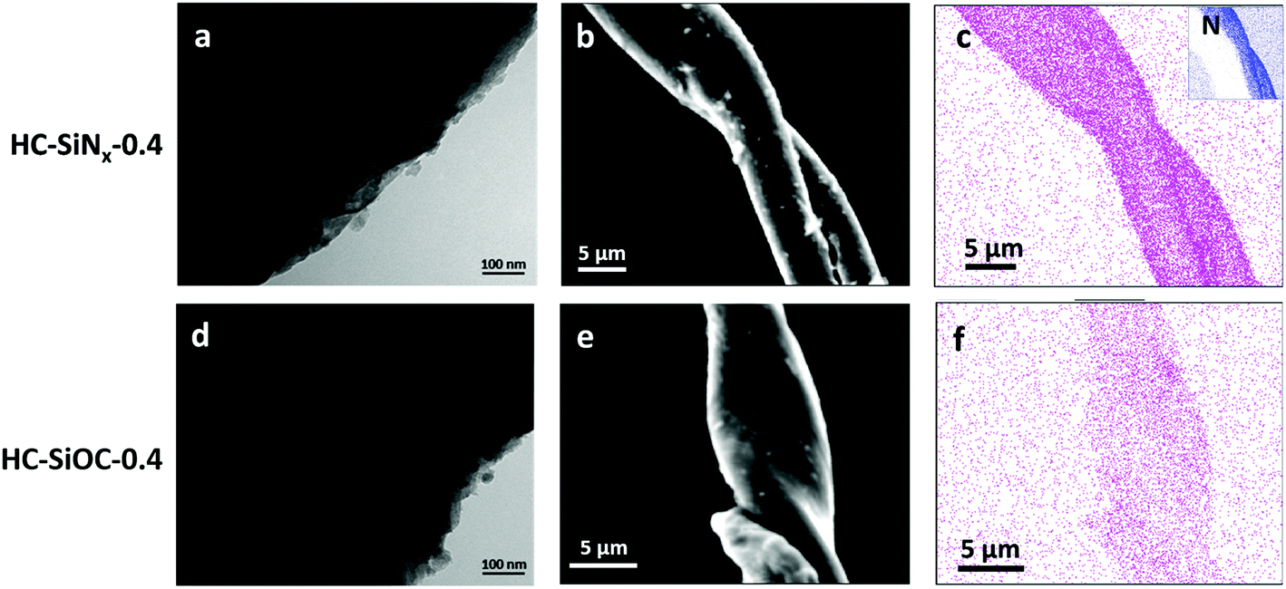 | ||
| Fig. 1 TEM images (left), SEM images (centre) and EDX maps (right) of (a–c) HC-SiNx-0.4 and (d–f) HC-SiOC-0.4 composites. Purple and blue dots in the EDX maps represent the locations where silicon and nitrogen were detected, respectively. | ||
Phase compositions were investigated by XRD. No peaks were observed in the hard carbon and silicon nitride composites other than the usual two broad reflections from hard carbon (Fig. 2a), indicating that the silicon-nitride component is amorphous. Table 1 shows the graphitic interlayer distance (d002) of hard carbon in the composites. An expansion of the interlayer spacing in the hard carbon could favour sodium ion insertion,37 however here we find that the samples containing silicon nitride/oxycarbide exhibit the same d002 interlayer distance as hard carbon produced under the same conditions. Fig. 2b shows the XRD patterns of hard carbon coated with silicon oxycarbide. In this case, in addition to the two broad peaks from hard carbon, a small peak corresponding to 3C cubic silicon carbide38 appears around 35.7°. Only a small fraction of the silicon carbide component is crystallised, as can be seen by comparing the heights of silicon carbide reflections in samples prepared at 1200 and 1400 °C (compare Fig. 2 with Fig. S2, ESI†). The amorphous-crystalline transition temperature of silicon nitride varies from 1200 to 1500 °C, depending on synthesis method and the properties of the amorphous material,39,40 while that of silicon carbide is typically around 900 °C.41 Hence it is unsurprising that the amorphous silicon oxycarbide partially crystallised to cubic silicon carbide during pyrolysis at 1200 °C.
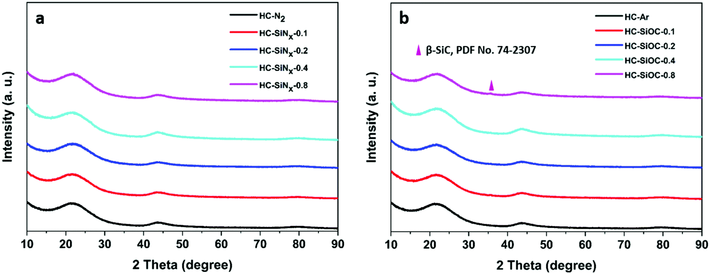 | ||
| Fig. 2 XRD patterns of composites with (a) silicon nitride or (b) silicon oxycarbide produced by reacting cellulose with different volumes of silicon chloride (as labelled) and carbonisation under nitrogen or argon at 1200 °C. | ||
| Samples | SiNx or Si(O)C content from TGA (wt%) | BET surface area (cm2 g−1) | d 002 (Å) | I D/IG |
|---|---|---|---|---|
| HC-N2 | — | 75 | 4.040 (6) | 2.2 |
| HC-SiNx-0.1 | 5.0 ± 0.9 | 75 | 4.029 (9) | 2.2 |
| HC-SiNx-0.2 | 5.5 ± 1.0 | 64 | 4.024 (7) | 2.5 |
| HC-SiNx-0.4 | 7.6 ± 1.3 | 84 | 4.004 (9) | 2.5 |
| HC-SiNx-0.8 | 11.4 ± 2.0 | 99 | 4.042 (7) | 2.2 |
| HC-Ar | — | 86 | 4.020 (7) | 2.6 |
| HC-SiOC-0.1 | 4.2 ± 0.8 | 41 | 4.002 (8) | 2.3 |
| HC-SiOC-0.2 | 4.3 ± 0.9 | 43 | 4.004 (8) | 2.3 |
| HC-SiOC-0.4 | 4.8 ± 1.0 | 26 | 4.002 (7) | 2.3 |
| HC-SiOC-0.8 | 5.5 ± 1.1 | 62 | 4.028 (8) | 2.2 |
The amount of silicon-containing phase (SiNx or SiOC) in the composites was evaluated by thermogravimetric analysis, TGA. Details of the calculations are given in the ESI† and examples of the raw experimental data are shown in Fig. S3 and Table S1 (ESI†). The mass loss between 400 and 650 °C can be attributed to the burning of hard carbon. Silicon nitride and silicon carbide have high oxidation resistance and their oxidation to silicon oxide requires higher temperatures.42,43 However, non-stoichiometric compositions of the nitride or oxycarbide phases could partially oxidise at lower temperatures, thus producing some uncertainty in the evaluation of the content of SiNx or SiOC in the composites. Hence the range of possible values for the loadings were calculated by assuming that Si3N4 or SiN and SiC or SiOC are present in the composite and that they are either fully oxidised to silicon dioxide or left unoxidised. In this way the mass content range of SiNx in HC-SiNx-0.4 is calculated as 7.6 ± 1.3%, and the Si(O)C in HC-SiOC-0.4 is 4.8 ± 1.0%.
The Raman spectra of the hard carbon composites with highest loading of silicon nitride or silicon oxycarbide (Fig. S4, ESI†) contained small peaks related to silicon nitride (∼440, 800 cm−1)44,45 or silicon carbide (∼860 cm−1).46 The presence of humps below 600 cm−1 corresponds to the Si–O–Si47 bonds or Si–C.48 Due to the better Raman efficiency of C–C bonds than Si–C, Si–N and Si–O, with amorphous silicon nitride and mainly amorphous silicon oxycarbides in the hard carbon composites, the Si–N and Si–C Raman bands were almost unobservable.49 Two broad peaks (Fig. S5, ESI†) with Raman shift of 1310 and 1610 cm−1 correspond to the D and G bands in hard carbon, respectively. The G band involves the in-plane bond-stretching motion of sp2 carbon atoms while the D band is a breathing mode of the six-carbon rings that becomes active in the presence of disorder.50 The typical broad D- and G-peaks found here, reveal a highly disordered structure of hard carbon,50 similar to other hard carbons used in sodium ion batteries.51,52 Fitting of the Raman spectra (Fig. S6, ESI†) was done using Lorentzian functions for the D and G bands, and a Gaussian function for the G3, as done previously.53
The nitrogen adsorption/desorption isotherms of hard carbon composites with silicon nitride and oxycarbide (Fig. S7, ESI†) show type IV behaviour and H4 type hysteresis. In these hysteresis loops, complete closure points should appear at nitrogen's boiling point around P/P0 = 0.42. However, for some materials containing micropores, low pressure hysteresis can be extended to the lowest attainable pressures as seen in these isotherms.54–56 The pore size distributions calculated from the isotherms (Fig. S8, ESI†) show the presence of both micro and mesopores. BET surface areas are shown in Table 1. As the volume of silicon tetrachloride increases, the BET surface area does not change significantly for the silicon nitride composites, while the BET surface area of silicon oxycarbide composites decreases dramatically to half the value exhibited by pure hard carbon. The reason may be the different amorphous-crystalline transition temperatures of silicon nitride and silicon carbide as discussed above. Even though only a small fraction of the silicon carbide had crystallised at this temperature to the extent of showing diffraction features, some reorganisation and decrease in the surface area may still have occurred through annealing processes.
Fig. 3 shows exemplar Si 2p XPS spectra and curve-fitting for the SiNx and SiOC composites. The Pauling electronegativity of elements involved in our measurements increase in the order Si (1.8) < C < (2.5) < N (3.0) < O (3.5).57 Thus the Si 2p binding energy peak shifts to higher position with increasing electronegativity of the neighbouring atoms. For the SiNx composites, the fitted Si 2p spectrum consists of two intense peaks around 103.6 and 102.1 eV corresponding to Si–O and Si–N, respectively,43,58,59 and one weak peak around 102.8 eV, which can be attributed to silicon oxynitride.40,60 The presence of SiNx can be further confirmed by the N 1s spectrum in Fig. 3b. The binding energy at 397.7 and 399.6 eV corresponds to the SiNx and silicon oxynitride, respectively.22,61 For comparison, the spectra for SiOC composites show an Si–O peak around 103.7 eV and two more peaks around 100.9 and 102.1 eV, which agree well with Si–C and Si–O–C, respectively.62–64 No obvious Si–C peak around 282.8 eV64 can be found in the C 1s (Fig. 3c) even though both components of Si and C are significant, which is similar to other reports.65,66 In both systems, oxygen appears in the spectra although no oxygen was deliberately introduced. At least some of that oxygen concentration is surface contamination after exposure to air, as reported previously.66–68
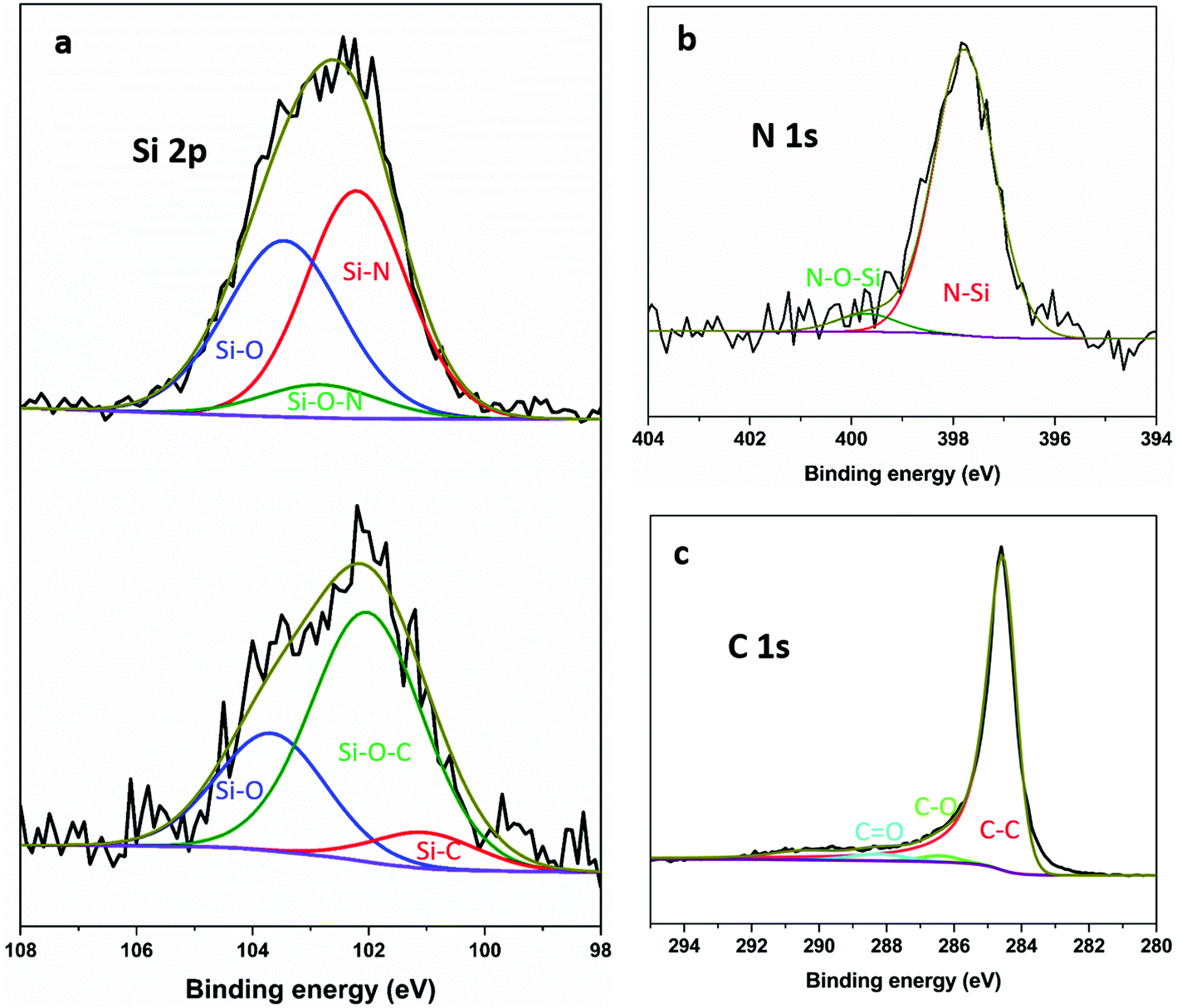 | ||
| Fig. 3 (a) Si 2p XPS spectrum and curve fitting of HC-SiNx-0.4 (top) and HC-SiOC-0.4 (bottom) composite materials; (b) N 1s spectrum of HC-SiNx-0.4; and (c) C 1s spectrum of HC-SiOC-0.4. | ||
The composites were suspended into inks and made into electrodes to investigate their electrochemical properties. The electrolyte was 1 mol dm−3 NaClO4 in EC/DEC. Sodium half-cells were assembled in the glove box and then multiple charge–discharge cycles were performed under galvanostatic conditions. Fig. 4 shows the first cycle charge/discharge profiles of hard carbon and silicon nitride/oxycarbide – hard carbon composite electrodes at 50 mA g−1. The hard carbon produced under nitrogen (HC-N2) delivered an oxidation capacity of 284 mA h g−1. As expected this capacity is lower than we have reported69 for hard carbon produced by pyrolysis of cotton wool at 1400 °C (302 mA h g−1), mainly due to a lower capacity in the plateau region (<0.1 V). The HC-SiNx electrodes showed oxidation capacities of 303, 312, 351 and 326 mA h g−1, with increasing silicon nitride content. The largest increase of 67 mA h g−1 in the oxidation (reversible) capacity was achieved in HC-SiNx-0.4, with incorporation of 7.9 wt% silicon nitride on HC. This increase in specific capacity (normalised by the mass of the whole active material, silicon nitride and hard carbon) corresponds to a very high specific capacity of 848 mA h g−1 when normalised by the mass of silicon nitride in the HC-SiNx-0.4 composite. Although the specific capacity of silicon nitride is lower than the theoretical capacity (2292 mA h g−1) that can be expected from a 4-electron conversion reaction, the capacity obtained here (848 mA h g−1) is still higher than can be achieved in the carbon based materials or has been reported for any other silicon-based system with sodium.33,34
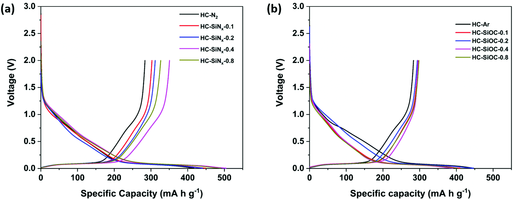 | ||
| Fig. 4 First cycle voltage–capacity plots for hard carbons (a and b) and hard carbon–silicon nitride (a) or hard carbon–silicon oxycarbide (b) composites in sodium half-cells with 1 mol dm−3 NaClO4 in EC/DEC electrolyte using a current of 50 mA g−1. | ||
Fig. 4b shows the first charge/discharge profile of hard carbon produced under argon (HC-Ar) and composite HC-SiOC electrodes at 50 mA g−1. The HC-Ar electrode exhibited a reversible oxidation capacity of 283 mA h g−1, while the composites delivered only small increases in oxidation capacity, with values of up to 295 mA h g−1. The increase of capacity is mainly in the plateau region below 0.1 V as seen previously in SiOC materials,31 which is good for the energy density in the full cell, but the improvements over hard carbon made at this lower temperature are not as large as those that can be made by increasing carbonisation temperature.
Fig. 5a shows the cycling performance of hard carbon and composites with silicon nitride. The reversible capacity at 50 mA g−1 after 50 cycles was up to 299 mA h g−1 in HC-SiNx electrodes, which can be compared to the 243 mA h g−1 obtained for the hard carbon produced under nitrogen, HC-N2. Therefore, the improvement in capacity obtained by the incorporation of silicon nitride is maintained during cycling. The capacity retention over 50 cycles was 85.6% in HC-N2 and 85.2% in HC-SiNx-0.4, suggesting that the capacity of the silicon nitride component in the electrode remained high when cycling the composite. The initial Coulombic efficiency (ICE) is 66% for HC-N2 and 69% for HC-SiNx-0.4. Both Coulombic efficiencies reach 96% in the second cycle, 98% in the ninth cycle and retain similar values over the remaining 40 cycles.
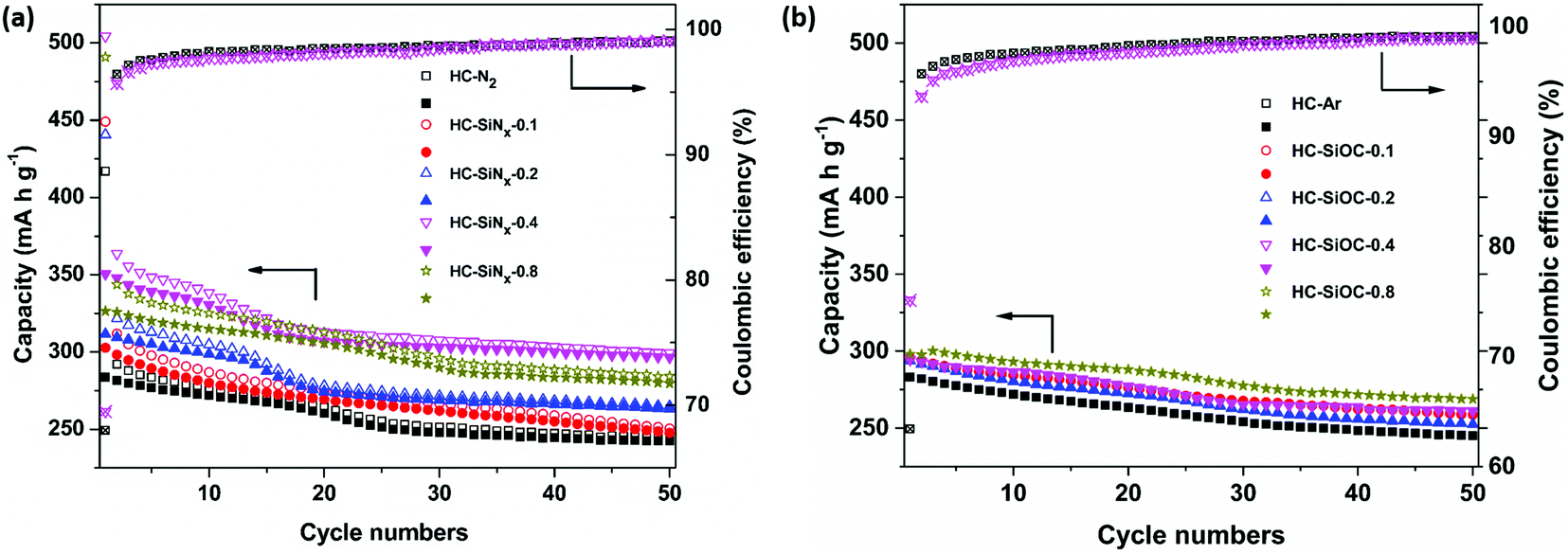 | ||
| Fig. 5 Cycling performance of hard carbon composites with (a) silicon nitride and (b) silicon oxycarbide in sodium half-cells with 1 mol dm−3 NaClO4 in EC/DEC electrolyte using a current of 50 mA g−1, with loadings as labelled. Open symbols show reduction capacity and closed symbols show oxidation capacity. | ||
Low ICE values are common in testing sodium negative electrode materials and the values obtained here can be ascribed to relatively high surface area (75 m2 g−1), in comparison with some previous work (e.g. pyrolysis of cotton at 1300 °C,70 38 m2 g−1). Improvements to ICE will need to be investigated in the future, but it has been shown that the use of PVDF binder has a detrimental effect on ICE values.71 The combination of soft and hard carbons has been demonstrated as a successful approach to improve ICE values.72 The use of ether-based electrolytes is also a successful approach to increase the ICE,73 which can be ascribed to the formation of a thin SEI.73,74 Pre-lithiation of hard carbon is also highly effective, producing values of ICE > 92%, and it has been shown to drastically improve the performance of full cells with a Na3V2(PO4)3 cathode, achieving nearly the full theoretical capacity.75
The characterisation of the capacity retention with cycling in sodium half-cells can be misleading, and an underestimation of the true cycling stability of the material under study. Bommier et al. showed that reaction of the sodium counter/reference electrode with the electrolyte forms an SEI whose resistance increases with time.71 Consequently, cycling in two-electrode sodium half cells, as in the present study, produces a decrease in capacity with cycling because the voltage window progressively becomes narrower as the SEI resistance of the sodium counter/reference electrode increases with time. Similar effects were observed in our previous study of hard carbon electrodes modified with vanadium nitride coating.69
Regarding the performance of the silicon oxycarbide composite electrodes, Fig. 5b shows that after 50 cycles the reversible capacity is around 260 mA h g−1, and the capacity retention is 88.1% (Fig. 5b), while the hard carbon obtained in an argon atmosphere, HC-Ar, showed a capacity of 245 mA h g−1 and capacity retention of 86.5%. Due to the decrease of BET surface area after loading silicon oxycarbides on hard carbon, the composites show a higher ICE (around 72%) than the pure hard carbon (63%).
XPS measurements on electrodes that had been reduced (sodiated) in sodium half-cells were carried out without air exposure, by disassembling the cells inside the argon glove box and then transferring the electrodes to the XPS measurement chamber using a vacuum suitcase. For comparison, additional measurements were done with electrodes that were housed in the sodium-half cells but held at the open circuit potential for the same amount of time as those electrodes that were reduced (sodiated). The latter measurements are referred to as ‘before reduction’, while those done with the electrodes that had been reduced in sodium half-cells are called ‘after reduction’. Ar-ion sputtering was carried out with an etching rate of 2 nm min−1. The Si 2p spectra of the electrodes after 5 minutes of etching are shown in Fig. 6. The etched HC-SiNx-0.4 electrode shows a Si–N peak at 102.2 eV, consistent with silicon nitride, and very little oxide. The reduction in oxide concentration compared with Fig. 3 supports the assignment of the silicon-containing component of this composite as silicon nitride, although this clearly undergoes surface oxidation when exposed to air and hence in the cells studied that surface oxide will also have been present. The etched HC-SiOC-0.4 electrode shows Si–O, Si–O–C and Si–C peaks at 103.7, 102.0 and 100.9 eV, respectively, but the SiC peak is stronger than in Fig. 3. Hence the oxycarbide has also undergone some surface oxidation, but likely contains oxide throughout.
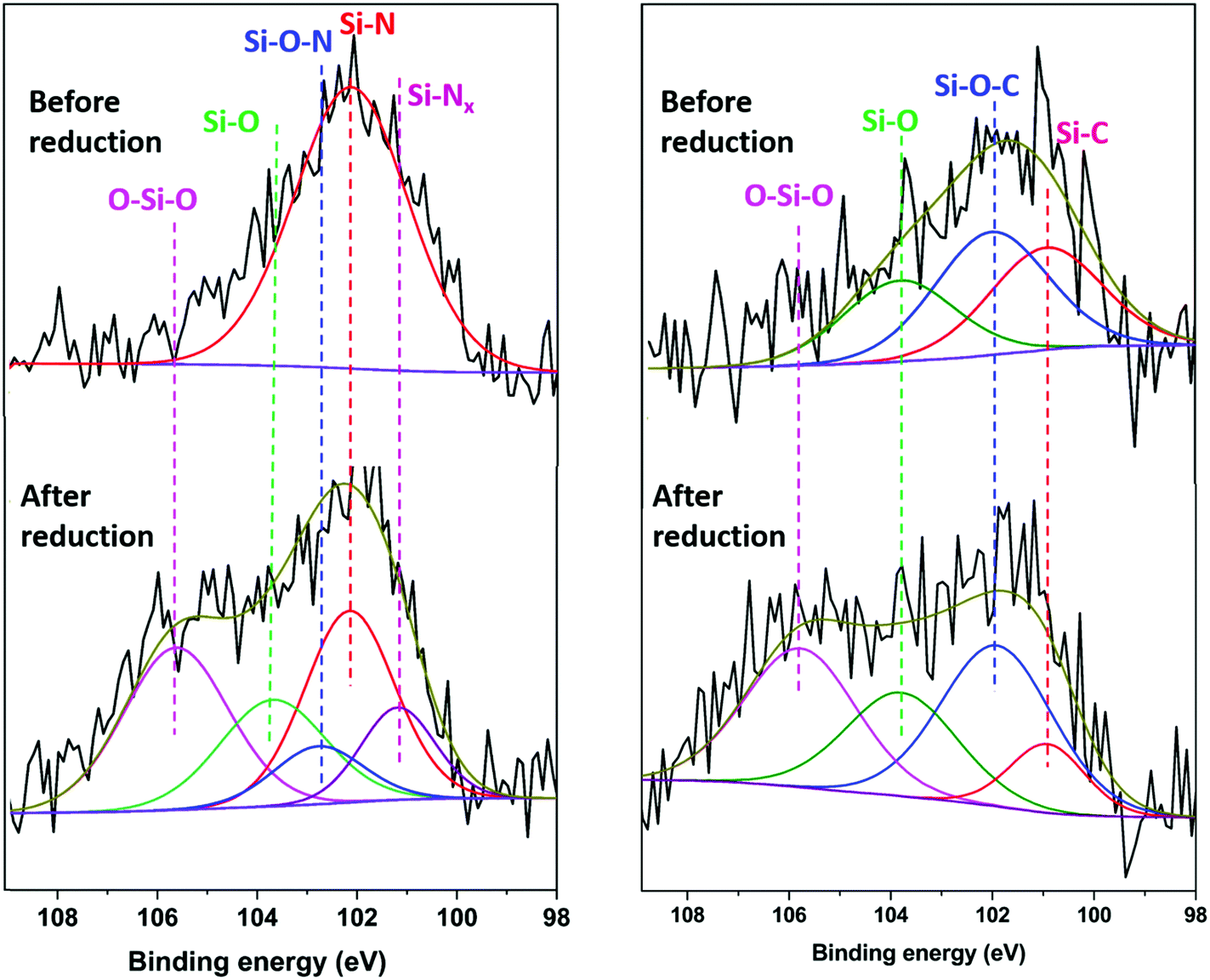 | ||
| Fig. 6 Si 2p XPS spectra for HC-SiNx-0.4 and HC-SiOC-0.4 composite electrodes before and after reduction in sodium half-cells with 1 mol dm−3 NaClO4 in EC/DEC electrolyte using a current of 50 mA g−1 to the lower potential limit of 5 mV vs. Na+/Na. Each sample was Ar+ etched for 5 min before the measurements. | ||
Surprisingly, after reduction (sodiation) in sodium half-cells, the intensity of the Si–N and Si–C environments became smaller and significant concentrations of SiOx species (104.5–106.7 eV)76 were observed, for both the silicon nitride and the oxycarbide samples that had undergone electrochemical reduction. The spectra in Fig. 6 were for samples etched under the same conditions as the uncycled samples, and the samples were handled in the glove box during the same session of measurements. Samples that had not undergone etching had even larger oxide concentrations (Fig. S10, ESI†). The etched HC-SiNx-0.4 Si 2p data requires two silicon–nitrogen environments to achieve a good fit, a defective Si–Nx (x < 1) at 101.2 eV and a more typical Si–N at 102.2 eV, and this is consistent with two environments in the N 1s spectrum (Fig. S11, ESI†).22 The Si–O–N, Si–O, and O–Si–O peaks are at 102.8, 103.6 and 105.6 eV.77 The binding energies of the Si–C, Si–O–C and Si–O peaks in the HC-SiOC-0.4 Si 2p signals were 103.7, 102.0 and 100.9 eV. The presence of similar O–Si–O peaks have been observed in XPS studies of silicon electrodes in lithium cells, where they were attributed to reactions of amorphous silicon with the carbonate electrolytes during formation of a solid–electrolyte interphase (SEI) layer.76,78 It is likely that some fraction of our amorphous SiNx and SiOC particles were reduced to amorphous silicon during electrochemical reduction, but that the particle surfaces then reacted with the electrolyte to produce SiOx species. The continuous high capacity during cycling suggests that this is a surface effect that is deep enough for the etching that was carried out to not remove it completely, but not a major fraction of the active material.
The first cycle differential capacity plots of composites with silicon nitride and silicon oxycarbide (Fig. S12 and S13, ESI†) have sharp peaks around 0.1 V vs. Na+/Na related to the sodium insertion/disinsertion from hard carbon.31,79 In addition, broad peaks around 0.5 and 1.1 V vs. Na+/Na are only observed in the first reduction and likely correspond to electrochemical reduction of electrolyte species during SEI formation.80 The comparison of the first cycle differential capacity plots as a function of the cycle number (Fig. S14 and S15, ESI†) reveals that the peak to peak separation of the peaks around 0.1 V vs. Na+/Na, associated with sodium insertion/deinsertion from hard carbon, increases after 50 cycles. This is in line with the observed increase in the impedance with cycling: Fig. S16 and S17 (ESI†) show that the effective charge-transfer resistance (as identified as the width of the impedance depressed semicircle) increases after 50 cycles. However, it should be noted that the quantitative analysis of impedance or differential capacity plots from sodium half cells should be done with care, since the results can be markedly affected by changes in the properties of the passivation layer of the sodium counter-reference electrode, thus possibly masking the changes in the properties of the working hard-carbon composite electrode.71,74,81
The C 1s spectra of HC-SiNx-0.4 samples before and after reduction in sodium half cells are shown in Fig. 7. The spectrum before reduction showed peaks at 290.8, 288.8, 286.2 and 284.6 eV corresponding to CH2–CF2, C![[double bond, length as m-dash]](https://www.rsc.org/images/entities/char_e001.gif) O, C–O, and C–C environments, respectively.82–86 The CH2–CF2 is ascribed to the PVDF binder used in the electrode. The presence of CO and C–O signals in the spectrum of the electrode before reduction can be ascribed to the presence of oxidic species due to surface contamination and/or defect formation (carbonyl/carboxylic group) during ink preparation. After reduction, a NaxC component (283.6 eV) appeared due to the sodiation of hard-carbon.82,83 A growth in the CO signal (288.8 eV) could be ascribed to formation of Na2CO3 and ROCO2Na (R = alkyl groups of different chain length) products from the degradation of EC and/or DEC,82,87,88 but for the conditions here employed, the reduction of the composite electrodes did not produce a significant growth of the CO environment. On the other hand, a marked increase in the intensity of the C–O (286.2 eV) environment is observed, consistent with the formation of RCH2ONa from EC and/or DEC reduction.82,86,89 It has been suggested that RCH2ONa species can facilitate sodium ion transport,90 thus facilitating the sodiation reactions of hard carbon. The C 1s depth profile (Fig. S18 and S19, ESI†) of a sample after the first reduction showed an increasing intensity of C–C species with etching depth, which is associated with contributions from the hard carbon located underneath the SEI layer.82 The C 1s peaks corresponding to O-containing species (i.e. Na2CO3, ROCO2Na and RCH2ONa, Fig. S13 and S14, ESI†) decrease with increasing sputtering time, while the signal associated to the NaxC component increases with increasing the sputtering time, consistent with previous work.82,88
O, C–O, and C–C environments, respectively.82–86 The CH2–CF2 is ascribed to the PVDF binder used in the electrode. The presence of CO and C–O signals in the spectrum of the electrode before reduction can be ascribed to the presence of oxidic species due to surface contamination and/or defect formation (carbonyl/carboxylic group) during ink preparation. After reduction, a NaxC component (283.6 eV) appeared due to the sodiation of hard-carbon.82,83 A growth in the CO signal (288.8 eV) could be ascribed to formation of Na2CO3 and ROCO2Na (R = alkyl groups of different chain length) products from the degradation of EC and/or DEC,82,87,88 but for the conditions here employed, the reduction of the composite electrodes did not produce a significant growth of the CO environment. On the other hand, a marked increase in the intensity of the C–O (286.2 eV) environment is observed, consistent with the formation of RCH2ONa from EC and/or DEC reduction.82,86,89 It has been suggested that RCH2ONa species can facilitate sodium ion transport,90 thus facilitating the sodiation reactions of hard carbon. The C 1s depth profile (Fig. S18 and S19, ESI†) of a sample after the first reduction showed an increasing intensity of C–C species with etching depth, which is associated with contributions from the hard carbon located underneath the SEI layer.82 The C 1s peaks corresponding to O-containing species (i.e. Na2CO3, ROCO2Na and RCH2ONa, Fig. S13 and S14, ESI†) decrease with increasing sputtering time, while the signal associated to the NaxC component increases with increasing the sputtering time, consistent with previous work.82,88
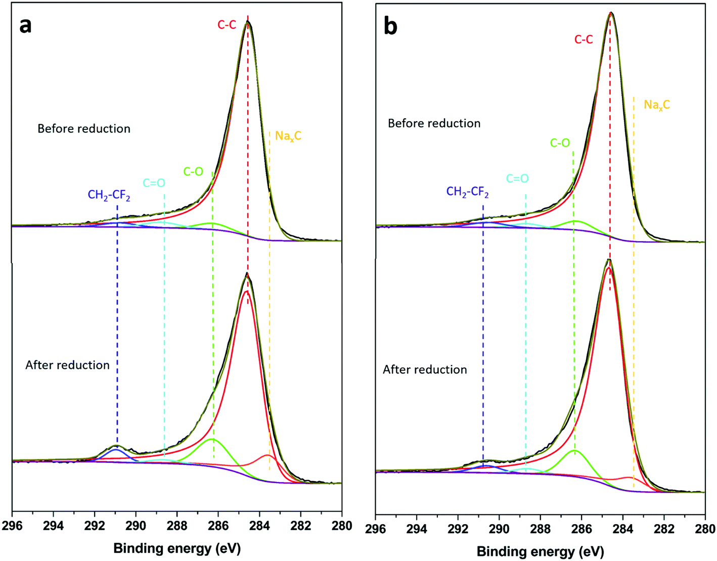 | ||
| Fig. 7 C 1s spectra of (a) HC-SiNx-0.4 and (b)HC-SiOC-0.4 composite electrodes before and after reduction in sodium half-cells. All experimental conditions as in Fig. 6. | ||
Conclusions
Hard carbon with a thin and homogenously distributed coating of amorphous silicon nitride (SiNx) or silicon oxycarbide (SiOC) nanoparticles has been produced, and the composite material has been tested as anode for sodium-ion batteries. The silicon oxycarbide-hard carbon composite with 4.9 wt% SiOC delivered a reversible (desodiation) capacity of 261 mA h g−1 at 50 mA g−1. The silicon nitride-hard carbon with 7.9%wt SiNx delivered a reversible (desodiation) capacity of 351 mA h g−1 at 50 mA g−1, while the hard carbon carbonised in nitrogen, without the silicon nitride coating, delivered a capacity of 284 mA h g−1. The increase in capacity of 67 mA h g−1 achieved with the silicon nitride-based composite, compared to the pure hard carbon, corresponds to a capacity of 848 mA h g−1 when normalised by the mass of silicon nitride in the composite. This high capacity value is superior to any reported silicon-based material in sodium-ion cells, and it is also remarkable that the improvement in capacity is preserved with cycling (the difference in capacity remains 52 mA h g−1 after 50 cycles). The Si 2p XPS measurements of the electrodes before and after the electrochemical sodiation reaction shows that some fraction of our amorphous SiNx and SiOC particles were reduced to amorphous Si during electrochemical reduction, but that the particle surfaces then reacted with the electrolyte to produce SiOx species. The fact that the electrodes could sustain high capacity with cycling indicates that the formation of the silicon oxide species is confined to the near-surface region. These results evidence that controlling the surface reactivity of amorphous SiNx, amorphous Si and their interaction with the hard carbon surface is crucial to design composite electrodes able to deliver high capacity. The new synthesis approach developed here has thus demonstrated the promise of amorphous silicon nitride coatings on hard carbon to produce a significant capacity enhancement, but much higher improvements in performance can be sought in further work via the optimisation of the hard carbon material, electrode formulation and electrolyte formulation, as well as the incorporation in full cells with a sodium-ion cathode in order to study the true capacity retention with cycling.Conflicts of interest
The authors have no conflicts to declare.Acknowledgements
H. C. thanks the China Scholarship Council (CSC) and University of Southampton for support. N. G. A. thanks the EPSRC for an early career fellowship (EP/N024303/1). We acknowledge Harwell XPS for collecting the XPS data and Professor Andrea Russell for access to the Raman spectrometer. Raw data supporting this study are openly available from the University of Southampton repository at https://doi.org/10.5258/SOTON/D2010.References
- N. Yabuuchi, K. Kubota, M. Dahbi and S. Komaba, Chem. Rev., 2014, 114, 11636–11682 CrossRef CAS PubMed.
- J. Y. Hwang, S. T. Myung and Y. K. Sun, Chem. Soc. Rev., 2017, 46, 3529–3614 RSC.
- M. D. Slater, D. Kim, E. Lee and C. S. Johnson, Adv. Funct. Mater., 2013, 23, 947–958 CrossRef CAS.
- L. Li, Y. Zheng, S. L. Zhang, J. P. Yang, Z. P. Shao and Z. P. Guo, Energy Environ. Sci., 2018, 11, 2310–2340 RSC.
- Y. Zhao, L. P. Wang, M. T. Sougrati, Z. X. Feng, Y. Leconte, A. Fisher, M. Srinivasan and Z. C. Xu, Adv. Energy Mater., 2017, 7, 1601424–1601493 CrossRef.
- Z. Z. Zhang, Y. C. Du, Q. C. Wang, J. Y. Xu, Y. N. Zhou, J. C. Bao, J. Shen and X. S. Zhou, Angew. Chem., Int. Ed., 2020, 59, 17504–17510 CrossRef CAS PubMed.
- Y. Zhang, Q. Shi, Y. Zhong and H. Wang, Sci. China: Chem., 2020, 63, 1557–1562 CrossRef CAS.
- X. Ge, S. Liu, M. Qiao, Y. Du, Y. Li, J. Bao and X. Zhou, Angew. Chem., Int. Ed., 2019, 58, 14578–14583 CrossRef CAS PubMed.
- X. Xu, L. Si, X. Zhou, F. Tu, X. Zhu and J. Bao, J. Power Sources, 2017, 349, 37–44 CrossRef CAS.
- H. Hou, X. Qiu, W. Wei, Y. Zhang and X. Ji, Adv. Energy Mater., 2017, 7, 1602898 CrossRef.
- B. Xiao, T. Rojo and X. Li, ChemSusChem, 2019, 12, 133–144 CrossRef CAS PubMed.
- D. Stevens and J. Dahn, J. Electrochem. Soc., 2000, 147, 1271–1273 CrossRef CAS.
- J. M. Stratford, P. K. Allan, O. Pecher, P. A. Chater and C. P. Grey, Chem. Commun., 2016, 52, 12430–12433 RSC.
- E. Olsson, J. Cottom, H. H. Au, Z. Y. Guo, A. C. S. Jensen, H. Alptekin, A. J. Drew, M. M. Titirici and Q. Cai, Adv. Funct. Mater., 2020, 30, 1908209–1908220 CrossRef CAS.
- F. Wu, M. Zhang, Y. Bai, X. Wang, R. Dong and C. Wu, ACS Appl. Mater. Interfaces, 2019, 11, 12554–12561 CrossRef CAS PubMed.
- Q. Wang, X. Zhu, Y. Liu, Y. Fang, X. Zhou and J. Bao, Carbon, 2018, 127, 658–666 CrossRef CAS.
- E. M. Lotfabad, J. Ding, K. Cui, A. Kohandehghan, W. P. Kalisvaart, M. Hazelton and D. Mitlin, ACS Nano, 2014, 8, 7115–7129 CrossRef CAS PubMed.
- X. Zhang, G. Pan, G. Li, J. Qu and X. Gao, Solid State Ionics, 2007, 178, 1107–1112 CrossRef CAS.
- M. Martín-Gil, M. E. Rabanal, A. Várez, A. Kuhn and F. García-Alvarado, Mater. Lett., 2003, 57, 3063–3069 CrossRef.
- N. Suzuki, R. B. Cervera, T. Ohnishi and K. Takada, J. Power Sources, 2013, 231, 186–189 CrossRef CAS.
- A. Ulvestad, J. P. Mæhlen and M. Kirkengen, J. Power Sources, 2018, 399, 414–421 CrossRef CAS.
- J. Yang, R. C. de Guzman, S. O. Salley, K. Y. S. Ng, B.-H. Chen and M. M.-C. Cheng, J. Power Sources, 2014, 269, 520–525 CrossRef CAS.
- A. Ulvestad, H. F. Andersen, J. P. Mæhlen, Ø. Prytz and M. Kirkengen, Sci. Rep., 2017, 7, 13315 CrossRef PubMed.
- A. Ulvestad, H. F. Andersen, I. J. T. Jensen, T. T. Mongstad, J. P. Mæhlen, Ø. Prytz and M. Kirkengen, Sci. Rep., 2018, 8, 8634 CrossRef PubMed.
- R. C. de Guzman, J. Yang, M. Ming-Cheng Cheng, S. O. Salley and K. Y. S. Ng, J. Mater. Chem. A, 2014, 2, 14577–14584 RSC.
- Z. Xiao, C. Lei, C. Yu, X. Chen, Z. Zhu, H. Jiang and F. Wei, Energy Storage Mater., 2020, 24, 565–573 CrossRef.
- S.-J. Kim, M.-C. Kim, S.-B. Han, G.-H. Lee, H.-S. Choe, D.-H. Kwak, S.-Y. Choi, B.-G. Son, M.-S. Shin and K.-W. Park, Nano Energy, 2016, 27, 545–553 CrossRef CAS.
- M. Weinberger, C. Pfeifer, S. Schindler, T. Diemant, R. J. Behm and M. Wohlfahrt-Mehrens, J. Mater. Chem. A, 2015, 3, 23707–23715 RSC.
- C. Chandra and J. Kim, Chem. Eng. J., 2018, 338, 126–136 CrossRef CAS.
- X. Dou, D. Buchholz, M. Weinberger, T. Diemant, M. Kaus, S. Indris, R. J. Behm, M. Wohlfahrt-Mehrens and S. Passerini, Small Methods, 2018, 3, 1800177 CrossRef.
- C. Chandra, H. S. Cahyadi, S. Alvin, W. Devina, J.-H. Park, W. Chang, K. Y. Chung, S. K. Kwak and J. Kim, Chem. Mater., 2019, 410–423 Search PubMed.
- M. Weinberger, J. Munding, M. Lindén and M. Wohlfahrt-mehrens, Energy Technol., 2018, 6, 1797–1804 CrossRef CAS.
- Y. Han, N. Lin, T. Xu, T. Li, J. Tian, Y. Zhu and Y. Qian, Nanoscale, 2018, 10, 3153–3158 RSC.
- L. Zhang, X. Hu, C. Chen, H. Guo, X. Liu, G. Xu, H. Zhong, S. Cheng, P. Wu, J. Meng, Y. Huang, S. Dou and H. Liu, Adv. Mater., 2017, 29, 1604708–1604715 CrossRef PubMed.
- D. A. Shirley, Phys. Rev. B: Solid State, 1972, 5, 4709–4714 CrossRef.
- H. Cheng, N. Garcia-Araez, A. L. Hector and S. Soule, Inorg. Chem., 2019, 58, 5776–5786 CrossRef CAS PubMed.
- S. Qiu, L. Xiao, M. L. Sushko, K. S. Han, Y. Shao, M. Yan, X. Liang, L. Mai, J. Feng, Y. Cao, X. Ai, H. Yang and J. Liu, Adv. Energy Mater., 2017, 7, 1700403 CrossRef.
- H. Braekken, Z. Kristallogr., 1930, 75, 572–573 CAS.
- M. Seher, J. Bill, F. Aldinger and R. Riedel, J. Cryst. Growth, 1994, 137, 452–456 CrossRef CAS.
- S. M. Castanho, R. Moreno and J. L. G. Fierro, J. Mater. Sci., 1997, 32, 157–162 CrossRef CAS.
- G. Foti, Appl. Surf. Sci., 2001, 184, 20–26 CrossRef CAS.
- X. Sun, H. T. Liu and H. F. Cheng, RSC Adv., 2017, 7, 47833–47839 RSC.
- D. H. Ma, H. J. Wang, M. Niu, J. B. Wen, H. Wei, J. Zhou, J. P. Fan and D. H. Zhang, Ceram. Int., 2018, 44, 1443–1447 CrossRef CAS.
- V. A. Volodin, M. D. Efremov, V. A. Gritsenko and S. A. Kochubei, Appl. Phys. Lett., 1998, 73, 1212–1214 CrossRef CAS.
- G. Yu, G. Chen and F. Zhang, Phys. Status Solidi B, 1989, 152, 73–78 CrossRef CAS.
- M. Wieligor, Y. Wang and T. W. Zerda, J. Phys.: Condens. Matter, 2005, 17, 2387–2395 CrossRef CAS.
- M. Dragomir, M. Valant, M. Fanetti and Y. Mozharivskyj, RSC Adv., 2016, 6, 21795–21801 RSC.
- Y. Ward, R. J. Young and R. A. Shatwell, J. Mater. Sci., 2004, 39, 6781–6790 CrossRef CAS.
- E. Bouillon, F. Langlais, R. Pailler, R. Naslain, F. Cruege, P. V. Huong, J. C. Sarthou, A. Delpuech, C. Laffon, P. Lagarde, M. Monthioux and A. Oberlin, J. Mater. Sci., 1991, 26, 1333–1345 CrossRef CAS.
- A. C. Ferrari and J. Robertson, Phys. Rev. B: Condens. Matter Mater. Phys., 2000, 61, 14095–14107 CrossRef CAS.
- M. Anji Reddy, M. Helen, A. Groß, M. Fichtner and H. Euchner, ACS Energy Lett., 2018, 3, 2851–2857 CrossRef CAS.
- E. Irisarri, A. Ponrouch and M. R. Palacin, J. Electrochem. Soc., 2015, 162, A2476–A2482 CrossRef CAS.
- T. Jawhari, A. Roid and J. Casado, Carbon, 1995, 33, 1561–1565 CrossRef CAS.
- K. S. W. Sing, D. H. Everett, R. A. W. Haul, L. Moscou, R. A. Pierotti, J. Rouquerol and T. Siemieniewska, Pure Appl. Chem., 1985, 57, 603–619 CAS.
- A. M. Puziy, O. I. Poddubnaya, A. Martinez-Alonso, F. Suarez-Garcia and J. M. D. Tascon, Carbon, 2002, 40, 1507–1519 CrossRef CAS.
- R.-L. Tseng and S.-K. Tseng, J. Colloid Interface Sci., 2005, 287, 428–437 CrossRef CAS PubMed.
- L. C. Pauling, The nature of the chemical bond and the structure of molecules and crystals. an introduction to modern structural chemistry, Cornell University Press, 2nd edn, 1960 Search PubMed.
- K. Sardar, R. Bounds, M. Carravetta, G. Cutts, J. S. Hargreaves, A. L. Hector, J. A. Hriljac, W. Levason and F. Wilson, Dalton Trans., 2016, 45, 5765–5774 RSC.
- H. A. Bland, E. L. H. Thomas, G. M. Klemencic, S. Mandal, D. J. Morgan, A. Papageorgiou, T. G. Jones and O. A. Williams, Sci. Rep., 2019, 9, 2911–2919 CrossRef PubMed.
- R. K. Brow and C. G. Patano, J. Am. Ceram. Soc., 1986, 69, 314–316 CrossRef CAS.
- C.-Y. Wu, C.-C. Chang and J.-G. Duh, J. Power Sources, 2016, 325, 64–70 CrossRef CAS.
- X. D. Huang, F. Zhang, X. F. Gan, Q. A. Huang, J. Z. Yang, P. T. Lai and W. M. Tang, RSC Adv., 2018, 8, 5189–5196 RSC.
- W. K. Choi, T. Y. Ong, L. S. Tan, F. C. Loh and K. L. Tan, J. Appl. Phys., 1998, 83, 4968–4973 CrossRef CAS.
- S. Contarini, S. P. Howlett, C. Rizzo and B. A. De Angelis, Appl. Surf. Sci., 1991, 51, 177–183 CrossRef CAS.
- L. C. Chen, C. K. Chen, S. L. Wei, D. M. Bhusari, K. H. Chen, Y. F. Chen, Y. C. Jong and Y. S. Huang, Appl. Phys. Lett., 1998, 72, 2463–2465 CrossRef CAS.
- Y. Gao, J. Wei, D. H. Zhang, Z. Q. Mo, P. Hing and X. Shi, Thin Solid Films, 2000, 377-378, 562–566 CrossRef CAS.
- F. J. Gomez, P. Prieto, E. Elizalde and J. Piqueras, Appl. Phys. Lett., 1996, 69, 773–775 CrossRef CAS.
- A. Y. Liu and M. L. Cohen, Phys. Rev. B: Condens. Matter Mater. Phys., 1990, 41, 10727–10734 CrossRef CAS PubMed.
- H. Cheng, N. Garcia-Araez and A. L. Hector, ACS Appl. Energy Mater., 2020, 3, 4286–4294 CrossRef CAS.
- Y. Li, Y.-S. Hu, M.-M. Titirici, L. Chen and X. Huang, Adv. Energy Mater., 2016, 6, 1600659 CrossRef.
- C. Bommier, D. Leonard, Z. Jian, W. F. Stickle, P. A. Greaney and X. Ji, Adv. Mater. Interfaces, 2016, 3, 1600449 CrossRef.
- F. Xie, Z. Xu, A. C. S. Jensen, H. Au, Y. Lu, V. Araullo-Peters, A. J. Drew, Y. S. Hu and M. M. Titirici, Adv. Funct. Mater., 2019, 29, 1901072 CrossRef.
- J. Zhang, D.-W. Wang, W. Lv, S. Zhang, Q. Liang, D. Zheng, F. Kang and Q.-H. Yang, Energy Environ. Sci., 2017, 10, 370–376 RSC.
- Y. Rangom, R. R. Gaddam, T. T. Duignan and X. S. Zhao, ACS Appl. Mater. Interfaces, 2019, 11, 34796–34804 CrossRef CAS PubMed.
- B. Xiao, F. A. Soto, M. Gu, K. S. Han, J. Song, H. Wang, M. H. Engelhard, V. Murugesan, K. T. Mueller, D. Reed, V. L. Sprenkle, P. B. Balbuena and X. Li, Adv. Energy Mater., 2018, 8, 1801441 CrossRef.
- Y. Yin, E. Arca, L. Wang, G. Yang, M. Schnabel, L. Cao, C. Xiao, H. Zhou, P. Liu, J. Nanda, G. Teeter, B. Eichhorn, K. Xu, A. Burrell and C. Ban, ACS Appl. Mater. Interfaces, 2020, 12, 26593–26600 CrossRef CAS PubMed.
- B. H. Chen, S. I. Chuang, W. R. Liu and J. G. Duh, ACS Appl. Mater. Interfaces, 2015, 7, 28166–28176 CrossRef CAS PubMed.
- K. Prasanna, T. Subburaj, Y. N. Jo, P. Santhoshkumar, S. K. S. S. Karthikeyan, K. Vediappan, R. M. Gnanamuthu and C. W. Lee, Sci. Rep., 2019, 9, 3318 CrossRef CAS PubMed.
- P. Wang, K. Zhu, K. Ye, Z. Gong, R. Liu, K. Cheng, G. Wang, J. Yan and D. Cao, J. Colloid Interface Sci., 2020, 561, 203–210 CrossRef CAS PubMed.
- E. Memarzadeh Lotfabad, P. Kalisvaart, A. Kohandehghan, D. Karpuzov and D. Mitlin, J. Mater. Chem. A, 2014, 2, 19685–19695 RSC.
- F. Linsenmann, D. Pritzl and H. A. Gasteiger, J. Electrochem. Soc., 2019, 166, A3668–A3674 CrossRef CAS.
- G. G. Eshetu, T. Diemant, M. Hekmatfar, S. Grugeon, R. J. Behm, S. Laruelle, M. Armand and S. Passerini, Nano Energy, 2019, 55, 327–340 CrossRef CAS.
- M. Carboni, J. Manzi, A. R. Armstrong, J. Billaud, S. Brutti and R. Younesi, ChemElectroChem, 2019, 6, 1745–1753 CrossRef CAS.
- Y. Pan, Y. Zhang, B. S. Parimalam, C. C. Nguyen, G. Wang and B. L. Lucht, J. Electroanal. Chem., 2017, 799, 181–186 CrossRef CAS.
- J. Fondard, E. Irisarri, C. Courrèges, M. R. Palacin, A. Ponrouch and R. Dedryvère, J. Electrochem. Soc., 2020, 167, 070526 CrossRef CAS.
- A. Ponrouch, R. Dedryvère, D. Monti, A. E. Demet, J. M. Ateba Mba, L. Croguennec, C. Masquelier, P. Johansson and M. R. Palacín, Energy Environ. Sci., 2013, 6, 2361 RSC.
- Y. Wang, S. Nakamura, M. Ue and P. B. Balbuena, J. Am. Chem. Soc., 2001, 123, 11708–11718 CrossRef CAS PubMed.
- K. Li, J. Zhang, D. Lin, D. W. Wang, B. Li, W. Lv, S. Sun, Y. B. He, F. Kang, Q. H. Yang, L. Zhou and T. Y. Zhang, Nat. Commun., 2019, 10, 725–734 CrossRef CAS PubMed.
- A. Schechter, D. Aurbach and H. Cohen, Langmuir, 1999, 15, 3334–3342 CrossRef CAS.
- C. Wang, L. Wang, F. Li, F. Cheng and J. Chen, Adv. Mater., 2017, 29, 1702212 CrossRef PubMed.
Footnote |
| † Electronic supplementary information (ESI) available: Includes further electrochemical, diffraction, TGA, Raman, BET, XPS and EIS data. See DOI: 10.1039/d1ma00613d |
| This journal is © The Royal Society of Chemistry 2021 |