 Open Access Article
Supercooling suppression of phase change liquid metal–polydimethylsiloxane soft composites†
Jiexian
Ma
and
Pu
Zhang
 *
*
Department of Mechanical Engineering, State University of New York at Binghamton, Binghamton, NY 13902, USA. E-mail: pzhang@binghamton.edu
First published on 15th September 2021
Abstract
Supercooling is a critical issue of phase change liquid metal composites in their application as stiffness-tuning and shape memory materials because of the thermal hysteresis during heating–cooling cycles. Right now, researchers still have a poor understanding of the supercooling behavior of liquid metal composites; and there have not been any successful attempts to suppress their supercooling effect. The aims of this work are to investigate factors that affect supercooling of Field's metal particles and composites and to find methods that can suppress this supercooling effect. We found that the supercooling behavior is strongly affected by particle sizes, polymer matrix, alloy compositions, and oxide impurities.
1. Introduction
Liquid metals (LM) are metals and alloys with melting points close to room temperature,1e.g., Ga, EGaIn, Galinstan, and Field's metal (FM). In recent years, LMs have been increasingly used in multifunctional soft composites consisting of LMs embedded in a polymer or hydrogel matrix.2–8 These LM composites exhibit multiple promising features such as high thermal/electrical conductivity, low or tunable stiffness, and self-healing that are ideally suited for applications in wearable electronics, soft robotics, and thermal management.LM composites can be used as stiffness-tuning materials or shape memory composites by utilizing the solid–liquid phase transition of the embedded LM phases. Researchers have demonstrated such behaviors in LM lattices, co-continuous composites, and particulate composites.9–15 The LMs employed can have melting points either above (e.g. Ga, FM) or below (e.g. EGaIn, Galinstan) room temperature, depending on the applications. Compared to other stiffness-tuning materials such as shape memory polymers, phase change LM composites exhibit a number of advantages such as an ultra-wide range of transition temperatures (−100 °C–200 °C), designable stiffness, metallic features, faster response speed, versatile heating method, etc. Among the phase change LM composites, FM particle composites are the most popular ones, which have a transition temperature around 60 °C. For example, Chang et al. embedded supercooled FM particles in polydimethylsiloxane (PDMS) and achieved a mechanically triggered stiffness-tuning composite.16 They demonstrated the shape memory behavior of these composites as well. Later on, Buckner et al. successfully embedded FM particles into epoxy and achieved a significant change in stiffness by heating and cooling.17 Recently, Nasab et al. developed a FM-PDMS composite by making it electrically conductive and thus a fast response can be achieved through Joule heating.18
A critical issue affecting the stiffness-tuning performance of LM composites is supercooling (a.k.a. undercooling).19 Supercooling is a phenomenon where a material does not solidify when the temperature cools below its melting point Tm.20 Instead, solidification occurs when the temperature is further cooled down to a freezing point Tc (Tc < Tm) and the gap ΔT = Tm − Tc is called the degree of supercooling. Physically, supercooling is induced by an energy barrier that must be overcome to complete the liquid–solid phase transition. Early research done on the supercooling of metals was mainly for structural alloys, soldering alloys, and Ga.21–23 Researchers have identified multiple factors that affect the supercooling of metal droplets: alloy composition,24 impurity,25,26 size effect,27,28 carrier fluid or matrix,29 oxide film or surface coating,23 cooling rate, overheating,30 and pressure.31
For LM composites, there is still very little research done on their supercooling behaviors. Most of the existing research is about FM particles and composites. Thuo published a series of works on how to increase the supercooling of FM particles and utilize this feature for novel applications such as heating-free solders, mechanically triggered composites, etc.16,32,33 A significant supercooling degree (ΔT ≈ 40 °C) has been found in the FM-PDMS composites (1–20 μm particle size) synthesized by Chang et al.16 In addition, Kazem synthesized FM-PDMS composites with particles sizes ∼15 μm and found a supercooling degree ΔT ≈ 20–25 °C.34 Other than FM composites, Malakooti et al. characterized the supercooling behavior of EGaIn composites in different polymer matrices and found that the EGaIn particles can be kept in a supercooled state even at −80 °C.35 The previous studies mainly aimed at employing or enhancing the supercooling of LM particles. In contrast, such a supercooling behavior is usually unfavorable for reversible stiffness-tuning materials. For example, extra cooling effort and energy cost are required to complete the liquid–solid phase transition and stiffness changing. Such thermal hysteresis will slow down the response speed and jeopardize the stiffness-tuning performance. Therefore, investigating the supercooling suppression of LM composites is a vital problem to improve their stiffness-tuning performance.
Nevertheless, suppressing the supercooling of LM composites is a non-trivial problem. Conventional methods used to suppress the supercooling of metals include alloying,25,26 adding impurity,36 encapsulation,37 mechanical stimulus,32 and electric current.38 However, there have not been any successful attempts to suppress the supercooling of LM composites reported in the literature. It should be emphasized that once LM particles are embedded into a solid matrix, the supercooling behavior of the composite becomes very complicated. Various physical and chemical mechanisms may be involved during phase transition, such as the interaction between surface nucleation sites and matrix,39 volume expansion confinement,29,40 and the matrix's nucleation catalytic effect.27 Therefore, the aims of this work are to investigate factors that affect the supercooling of FM particles and composites and to discover ways to suppress supercooling.
2. Materials and methods
2.1. Materials
Field's metal (Bi32.5In51Sn16.5) was ordered from Rotometals (San Leandro, CA, USA). Zinc granules (−30 + 100 mesh, 99.8+ %, ACS reagent) and zinc oxide (ZnO, <1 μm, 99.90%) were acquired from Sigma-Aldrich. Ethanol (reagent grade) was obtained from Fisher Scientific. Polydimethylsiloxane compounds (PDMS, Sylgard 184) were purchased from Dow. Silicone oil (viscosity at 25 °C: 100 cSt) was acquired from Super Lube (Bohemia, NY, USA).2.2. Synthesis of BiInSnZn alloys
Zn granules (1 wt%, weight percentage) and FM palettes (99 wt%) were melted in a glass vial to form the new alloy Bi32.2In50.5Sn16.3Zn1. This alloy is called BiInSnZn later for simplicity purposes. The detailed synthesis procedure is as follows.(1) The metal mixture is heated on a hot plate at 100 °C and mixed by a magnetic stirrer at 100 rpm for 30 min. To reduce oxides, the mixing is performed in an Argon-protected environment.
(2) After mixing, the metals are maintained at 240 °C for 12 hours in a vacuum furnace (VWR model 1410) and then naturally cooled to room temperature.
(3) Repeat step 1 above followed by step 2 for 8 hours. Finally repeat step 1 again to obtain the alloy.
2.3. Synthesis of LM powder
All LM powders were synthesized by ultrasonic sonication.26,41–43 1 gram of bulk LM and 10 mL of ethanol were added to a 40 mL beaker. The beaker was heated to 70 °C on a hot plate to melt the LM. The LM and ethanol were sonicated by an ultrasonic probe (Branson Ultrasonics 450 Sonifier) with programmed amplitude and time. During the sonication process, the LM bubble is broken into micro-droplets that are stabilized by the native oxide layer (a few nm thick). The micro-droplet sizes can be controlled by the sonication amplitude and time. After the sonication process, the solution cooled down to room temperature naturally, allowing the LM micro-droplets to solidify. The powder solution was then filtered by a woven mesh filter to remove oversized particles. Stainless steel woven wire mesh (mesh size: 38 μm, 190 μm) and nylon 6 woven mesh sheets (mesh size: 15 μm, 30 μm) are used. Finally, the remaining solution was dried in a vacuum furnace at 25 °C to obtain the LM powders. The detailed synthesis parameters of FM powder are shown in Table 1.| Sample | Sonication parameter | Upper mesh size (passing) (μm) | Lower mesh size (retaining) (μm) | Final particle size (μm) |
|---|---|---|---|---|
| 1 | 20% Amp 1 min | 190 | 38 | 37–60 |
| 2 | 20% Amp 1 min | 38 | — | 8–20 |
| 3 | 30% Amp 12 min | 15 | — | 1–4 |
2.4. Synthesis of LM powder with oxide flakes
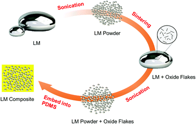
We discovered that the native oxide flakes of BiInSnZn are heterogeneous nucleation sites that will suppress supercooling. A novel synthesis method called sonication and sintering is proposed for generating and dispersing native oxide flakes into LM particles. The four steps of the synthesis process are illustrated in Fig. 1 and explained below.(1) Bulk LM of BiInSnZn is sonicated to form preliminary LM powders. The amplitude and time of the sonication can control the particle size. Powders are then washed with DI water to remove ethanol and dried at 45 °C. Thin native oxide layers are formed on the surface of LM powders.
(2) The preliminary LM powders are melted and sintered together to obtain a bulk LM with native oxide flake dispersion. In the sintering process, a Teflon beaker with 1 to 2 grams of LM powder is heated to 160 °C on a hot plate. Melted LM powders are then sintered and stirred with a Teflon rod to merge into a large LM bubble.
(3) A second sonication process is performed on the bulk LM with oxide flakes to generate the final LM powders. The final LM powders incorporate native oxide flakes.
(4) The final LM powders are filtered, dried, and mixed with PDMS to form a composite.
The essential idea of this synthesis method is that the native surface oxide layers of the preliminary LM powders are broken and dispersed into the bulk alloy during sintering and mixing. These native oxide flakes of BiInSnZn inside the final LM powders will serve as favorable heterogeneous nucleation sites that will reduce supercooling. In our method, the amount of oxide flakes in the sintered bulk material is directly controlled by the total surface area of preliminary LM powders. Thus, we can add more oxide flakes by using smaller preliminary LM powders or repeating the sonication and sintering process (steps 1 and 2) several times for the same piece of sintered bulk material. More oxide flakes will provide more nucleation sites and increase the nucleation probability, leading to supercooling suppression.
2.5. Synthesis of FM with ZnO nanoparticles
FM (99 wt%) and ZnO (1 wt%) are mixed by grinding using a mortar and pestle. The grinding is performed on a hot plate (120 °C) in an argon-filled glove box (LC Technology).2.6. Synthesis of LM composites
The LM powders (30%, volume fraction) are mixed with Sylgard 184 (A![[thin space (1/6-em)]](https://www.rsc.org/images/entities/char_2009.gif) :
:![[thin space (1/6-em)]](https://www.rsc.org/images/entities/char_2009.gif) B = 10
B = 10![[thin space (1/6-em)]](https://www.rsc.org/images/entities/char_2009.gif) :
:![[thin space (1/6-em)]](https://www.rsc.org/images/entities/char_2009.gif) 1) in a Teflon mold. The suspension is degassed in a vacuum furnace for 5 min at room temperature. After degassing, the suspension is cured at 60 °C for 5 hours.
1) in a Teflon mold. The suspension is degassed in a vacuum furnace for 5 min at room temperature. After degassing, the suspension is cured at 60 °C for 5 hours.
2.7. Sample characterization
Differential scanning calorimetry (DSC, TA Instruments Q200) is used to characterize the phase transitions of LM powders and LM composites. The weight of specimens is 5 ± 0.5 mg for powders and 10 ± 1 mg for composites. The specimen is equilibrated at 40 °C, then heated from 40 °C to 100 °C, and cooled from 100 °C to 0 °C at a rate of 10 °C min−1. From the DSC curves, the melting onset temperature (Tm) and freezing onset temperature (Tc) are calculated according to the ASTM E794 standard.44 Finally, the supercooling degree ΔT = Tm − Tc is obtained. Since the width of the freezing peak of the supercooled material can be extremely large, we also identify a freezing completion temperature (Te) from the DSC curve, which is taken as the temperature where the exothermic freezing peak returns to the baseline. Then, the width of the freezing peak is calculated by Tc − Te.A scanning electron microscope (SEM, Zeiss SUPRA 55 FESEM) was used to characterize the particle size and morphology of the LM powders. SEM images were processed and analyzed using the open-source image analysis software, ImageJ.45 The acquired grayscale images were denoised by Gaussian blur and converted to a binary image using an auto local threshold method.46 Connected particles are then segmented by a watershed algorithm. To analyze the size distributions of LM powders, the diameter of a circle with an equivalent area to a particle is computed, and 2–3 images of each sample are taken to capture the size variation. Elemental mapping is conducted by energy dispersive X-ray spectroscopy (EDS) using Zeiss EVO 50.
3. Results and discussion
In order to identify factors that influence the supercooling of LM materials, we studied the supercooling behaviors of different LM powders (FM, BiInSnZn, and BiInSnZn with native oxide flakes, and FM with ZnO nanoparticles) and their composites by DSC. The results are introduced and discussed below.3.1. Field's metal
FM powders of different sizes (1–4 μm, 9–17 μm, and 37–54 μm) were prepared using the method described in Section 2.3. The SEM images and particle size distribution of powders are given in Fig. 2, which indicate that higher ultrasonic intensity can pop LM into smaller particles. The shapes of LM particles in Fig. 2 are close to spheres, even though some large particles in Fig. 2c have irregular shapes, which are likely induced by the merging of small particles.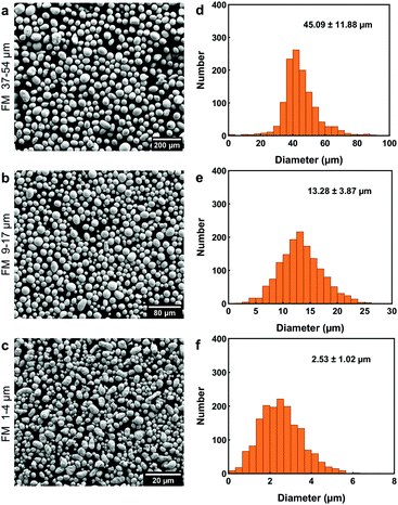 | ||
| Fig. 2 Particle size analysis of FM powders after filtration. (a–c) SEM images and (d–f) their size distribution: (a and d) 37–54 μm, (b and e) 9–17 μm, and (c and f) 1–4 μm. | ||
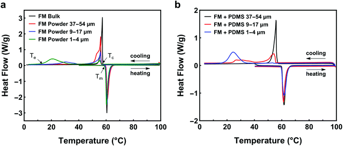
The supercooling of FM powders is strongly dependent on the particle size. Fig. 3a compares the DSC curves of bulk FM and powders. More profound supercooling phenomenon is observed in Fig. 3a as the particle size decreases. The supercooling of bulk FM is almost negligible (ΔT = 2.34 °C). The FM powders of 37–54 μm have a marginal supercooling effect (ΔT = 3.72 °C). However, as the powder size becomes smaller than 37 μm, the DSC result shows two exothermic freezing peaks. The second freezing peak starts at 39.5 °C for the powders of 9–17 μm and starts at 32.5 °C for the powders of 1–4 μm. Significant supercooling is observed for the powders of 1–4 μm, with the freezing completion temperature (Te) reaching 12.5 °C.
Experimental data indicate that the size effect is a major factor influencing the supercooling of FM-PDMS composites whereas the PDMS matrix has a negligible effect. Fig. 3b depicts the DSC results for the FM-PDMS composites. A SEM image of one typical composite sample is shown in Fig. S1 (ESI†). Fig. 3b shows that FM-PDMS composites exhibit notable supercooling when using small particles (1–4 μm, 9–17 μm). The supercooling degree and the width of freezing peak for composites with 1–4 μm particles are 28.02 °C and 13.3 °C, respectively. As particles become smaller, the supercooling effect of both powders and composites becomes more prominent, which is usually called the size effect of supercooling. Besides, we can infer from Fig. 2 and 3b that the minimum particle size of FM powders that do not incur supercooling in composites is ∼37 μm. Comparing Fig. 3a with b, we found that the PDMS matrix has almost negligible effects on the supercooling of FM particles. A direct comparison of the DSC curves of FM powders and their composites are shown in Fig. S2 (ESI†). We can observe that both the powder and the composite of 9–17 μm have two exothermic peaks during cooling. The first exothermic peak at a higher temperature represents the phase transition of microstructures with a lower activation barrier, and Te indicates the completed transition to a stable equilibrium phase. The two exothermic peaks observed might be related to the size effect of LM particles, competition of different types of nucleation sites, and the formation of a metastable phase.
Researchers have reported that thermal cycling may influence the supercooling behavior of some LMs, e.g. Ga. To elucidate this effect in FM-PDMS composites, we performed thermal cycling on the DSC testing (see Fig. S3a, ESI†) and found that the thermal cycling has no impact on the supercooling behavior of FM-PDMS composites.
3.2. BiInSnZn
Researchers have discovered that adding minor elements such as Ag, Cu, or Zn to LMs may suppress supercooling of the bulk alloy. For example, Massucco et al. almost eliminated the supercooling of bulk gallium by adding Ag or Cu in it;25 Wang and Liu successfully suppressed supercooling of bulk FM by adding 0.4 wt% of Zn.47 Nevertheless, it is still unclear whether this approach can suppress supercooling in LM powders and composites or not, due to the potential size or matrix effects. To answer this question, we modified FM by alloying it with Zn and finally obtained a new alloy BiInSnZn. Fig. 4a presents the DSC results of BiInSnZn powders and their composites. The powders were sonicated at 20% amplitude for 1 min (particle size 9–17 μm). The BiInSnZn-PDMS composite shows significant supercooling, while the powders have marginal supercooling. This implies that adding Zn can suppress supercooling of FM particles, but it fails to do so when these particles are embedded in PDMS. To elucidate whether this phenomenon is caused by the confinement stress or chemical interaction from PDMS, we dispersed BiInSnZn powders in silicone oil, which has the same chemical composition as PDMS. As shown in Fig. 4a, the DSC curves of BiInSnZn powders in PDMS and silicone oil have no difference, which indicates that the confinement stress does not contribute to the supercooling. Perepezko and Herlach et al. suggested that metal oxides formed at the surface of the melt are possible heterogeneous nucleation sites for liquid metal,27,39e.g., indium oxide on the surface of liquid indium. However, specific surface coating treatments to LM can deactivate these surface nucleates and thus increase the supercooling, as pointed out by Perepezko.24,27 Therefore, based on the findings in the literature, we concluded from Fig. 4 that native surface oxides of BiInSnZn are possible nucleation sites that help suppress supercooling of BiInSnZn particles but the surrounding PDMS or silicone oil matrix can deactivate these surface nucleation sites.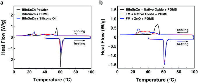 | ||
| Fig. 4 (a) DSC curves of BiInSnZn powder and its composite. (b) DSC curves for composite samples of FM with native oxide flakes, BiInSnZn with native oxide flakes, and FM with ZnO. | ||
3.3. BiInSnZn with native oxide flakes
Driven by the discovery that native oxides of BiInSnZn are possible nucleation sites if they have no contact with the matrix material, we hypothesize that dispersing native oxide flakes in BiInSnZn will suppress the supercooling of BiInSnZn particles and composites. To verify this hypothesis, we proposed a novel method called the sonication and sintering process to generate and disperse native oxide flakes into the LM particles. Specifically, bulk LM is sonicated into preliminary powders first, and then preliminary powders are mechanically sintered to obtain a bulk LM with native oxide flakes. See Section 2.4 for the details.Fig. 4b shows the thermal analysis for BiInSnZn-PDMS composites with native oxides. The BiInSnZn powders were prepared by sonicating the bulk alloy at 30% amplitude for 6 min (particle size 1–5 μm) first, sintering into bulk alloy with oxide flakes, and sonicating at 20% amplitude for 1 min to get the final powders (particle size 9–17 μm, see Fig. S4, ESI†). As shown in Fig. 4b, the BiInSnZn-PDMS composite with native oxide flakes has marginal supercooling (ΔT = 4.88 °C), which directly verifies our hypothesis. Dispersing native oxides into the BiInSnZn particles has successfully avoided the deactivation by the PDMS matrix. According to Fig. S3b (ESI†), the phase transition behavior of the BiInSnZn-PDMS composite with native oxides is stable under thermal cycling. Moreover, we can infer from Fig. S4b (ESI†) that the method we developed can suppress the supercooling of composites with particles of 5 μm or bigger. Fig. S5 (ESI†) presents the elemental mapping of FM particles and BiInSnZn particles with oxide flakes. They both exhibit phase segregation on the particle surface, consistent with the finding of Çınar et al.32 In Fig. S5b (ESI†), minor element Zn is uniformly distributed on the surface of BiInSnZn particles.
Can we achieve a similar supercooling suppression effect in FM-PDMS composites by adding its own native oxide flakes or ZnO nanoparticles? Fig. 4b shows the DSC results for such composites. The FM powders with native oxides were synthesized using the procedure described in the last paragraph. The FM with ZnO nanoparticles is prepared according to Section 2.5. As shown in Fig. 4b, the widths of the freezing peak for FM-PDMS composites with native oxides and ZnO are 30.4 °C and 27.3 °C, respectively. Besides, their freezing completion temperatures are both lower than 27 °C, indicating the composites of FM with oxide flakes or ZnO both have a profound supercooling effect. Our results suggest that the native oxides of FM or ZnO nanoparticles cannot serve as nucleation agents that will help suppress supercooling.
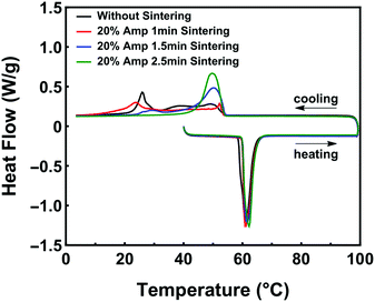
We also found that the amount of native oxide flakes dispersed in BiInSnZn powders affects the effectiveness of supercooling suppression. Fig. 5 presents this phenomenon. Since the total weight of oxide flakes is proportional to the total surface area of LM powders, we can control the amount of oxide flakes by tuning the size of LM powders prior to the sintering step. We prepared three types of preliminary LM powders by sonicating at 20% amplitude for 1 min, 1.5 min, and 2.5 min, respectively (see Fig. S6, ESI† for particle size analysis). After sintering, bulk LM with oxide flakes are sonicated at 20% amplitude for 1 min to form three types of final powders (9–17 μm) for the composites. As shown in Fig. 5, the values of freezing onset temperature are similar (∼55 °C) for the four composite samples. However, as the number of native oxides increases, the width of the freezing peak first increases and then decreases gradually. The smallest width of the freezing peak (∼12 °C) in Fig. 5 is achieved by the BiInSnZn-PDMS composite with the highest amount of native oxides. The results in Fig. 5 indicate that the powder with the largest amount of oxide flakes performs the best to suppress supercooling in the composite since more oxide flakes will provide more nucleation sites and increase nucleation probability. Fig. S7 (ESI†) illustrates another approach to introduce more native oxide flakes. The particles with a repeated sonication and sintering process exhibit improved supercooling suppression in composites as well.
4. Conclusions
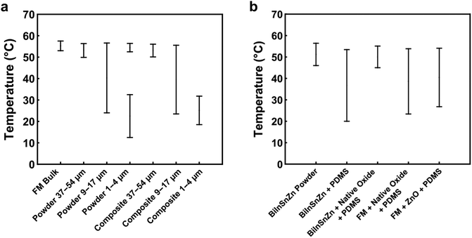
LM-filled soft composites are emerging multifunctional composites with promising applications as rigidity-tuning materials, shape memory composites, and thermal management materials. However, supercooling of the LM particles becomes a critical issue because it causes thermal hysteresis that deteriorates the thermo-mechanical performance and functions of these composites.In this work, we first studied the supercooling behavior of FM powders and composites. Summary plots of the major exothermic events of different specimens are shown in Fig. 6. We found that the supercooling effect is influenced by multiple factors such as particle size, matrix effect, and alloy composition. As the size of FM particles is decreased, the supercooling of FM powders and composites will be more prominent. We identified a critical particle size of 37 μm, below which the significant supercooling effect will occur in FM particles and composites. In order to suppress the supercooling effect, FM was alloyed with a minor element Zn. With experiments, we discovered that native surface oxides of BiInSnZn alloy could serve as surface nucleation sites that will suppress supercooling of its particles, but such an effect will be deactivated by the PDMS matrix. To circumvent this matrix effect, we developed a novel method to disperse native oxide flakes into the LM particles. Those dispersed oxide flakes of BiInSnZn work as volume nucleation sites to suppress the supercooling of LM powders and composites. In addition, we found that increasing the amount of native oxide flakes dispersed in the BiInSnZn alloy further enhances the effectiveness of supercooling suppression.
Although we focus on the supercooling suppression of FM, the method proposed here may be transferrable to other LMs as well, e.g., Ga, GaIn, and GaInSn. Of course, the detailed composition and processing parameters should be investigated for each metal or alloy in future studies.
Note that the LM composites studied in this paper are limited to particulate composites. The supercooling behavior may be reduced in other types of solid–liquid composites,48,49e.g. the ones with co-continuous or patterned networks. This is because the crystallization at a local point in the network structure can propagate to the whole composite. In contrast, any local crystallization in a particulate composite is confined in the particles.
Conflicts of interest
There are no conflicts to declare.Acknowledgements
This work is supported by the start-up fund from the Watson School of Engineering and Applied Science at SUNY Binghamton. We thank the support from the Small Scale Systems Integration and Packaging (S3IP) Center of Excellence, funded by New York Empire State Development's Division of Science, Technology and Innovation.References
- M. D. Dickey, Adv. Mater., 2017, 29, 1606425 CrossRef PubMed.
- A. Fassler and C. Majidi, Adv. Mater., 2015, 27, 1928–1932 CrossRef CAS PubMed.
- E. J. Markvicka, M. D. Bartlett, X. Huang and C. Majidi, Nat. Mater., 2018, 17, 618–624 CrossRef CAS PubMed.
- A. B. M. T. Haque, R. Tutika, R. L. Byrum and M. D. Bartlett, Adv. Funct. Mater., 2020, 30, 2000832 CrossRef CAS.
- L. Mou, J. Qi, L. Tang, R. Dong, Y. Xia, Y. Gao and X. Jiang, Small, 2020, 16, 2005336 CrossRef CAS PubMed.
- J. Yang, D. Tang, J. Ao, T. Ghosh, T. V. Neumann, D. Zhang, E. Piskarev, T. Yu, V. K. Truong, K. Xie, Y. Lai, Y. Li and M. D. Dickey, Adv. Funct. Mater., 2020, 30, 2002611 CrossRef CAS.
- Y. Xu, R. Rothe, D. Voigt, S. Hauser, M. Cui, T. Miyagawa, M. Patino Gaillez, T. Kurth, M. Bornhäuser, J. Pietzsch and Y. Zhang, Nat. Commun., 2021, 12, 2407 CrossRef CAS PubMed.
- S.-Y. Liao, X.-Y. Wang, X.-M. Li, Y.-J. Wan, T. Zhao, Y.-G. Hu, P.-L. Zhu, R. Sun and C.-P. Wong, Chem. Eng. J., 2021, 422, 129962 CrossRef CAS.
- F. Deng, Q.-K. Nguyen and P. Zhang, Addit. Manuf., 2020, 33, 101117 Search PubMed.
- A. Tonazzini, S. Mintchev, B. Schubert, B. Mazzolai, J. Shintake and D. Floreano, Adv. Mater., 2016, 28, 10142–10148 CrossRef CAS PubMed.
- M. D. Bartlett, N. Kazem, M. J. Powell-Palm, X. Huang, W. Sun, J. A. Malen and C. Majidi, Proc. Natl. Acad. Sci. U. S. A., 2017, 114, 2143–2148 CrossRef CAS PubMed.
- I. M. V. Meerbeek, B. C. M. Murray, J. W. Kim, S. S. Robinson, P. X. Zou, M. N. Silberstein and R. F. Shepherd, Adv. Mater., 2016, 28, 2801–2806 CrossRef PubMed.
- D. Yu, Y. Liao, Y. Song, S. Wang, H. Wan, Y. Zeng, T. Yin, W. Yang and Z. He, Adv. Sci., 2020, 7, 2000177 CrossRef CAS PubMed.
- M. J. Ford, C. P. Ambulo, T. A. Kent, E. J. Markvicka, C. Pan, J. Malen, T. H. Ware and C. Majidi, Proc. Natl. Acad. Sci. U. S. A., 2019, 116, 21438–21444 CrossRef CAS PubMed.
- T. L. Buckner, M. C. Yuen and R. Kramer-Bottiglio, IEEE, 2020 3rd IEEE International Conference on Soft Robotics (RoboSoft), New Haven, CT, USA, 2020, 259–265.
- B. S. Chang, R. Tutika, J. Cutinho, S. Oyola-Reynoso, J. Chen, M. D. Bartlett and M. M. Thuo, Mater. Horiz., 2018, 5, 416–422 RSC.
- T. L. Buckner, M. C. Yuen, S. Y. Kim and R. Kramer-Bottiglio, Adv. Funct. Mater., 2019, 29, 1903368 CrossRef CAS.
- A. M. Nasab, S. Sharifi, S. Chen, Y. Jiao and W. Shan, Adv. Intell. Syst., 2021, 3, 2000166 CrossRef.
- M. H. Zahir, S. A. Mohamed, R. Saidur and F. A. Al-Sulaiman, Appl. Energy, 2019, 240, 793–817 CrossRef CAS.
- J. P. Schaffer, A. Saxena, T. H. S. Jr, S. D. Antolovich and S. B. Warner, The Science and Design of Engineering Materials, McGraw-Hill Higher Education, 2nd edn, 2000 Search PubMed.
- D. Turnbull, J. Appl. Phys., 1950, 21, 1022–1028 CrossRef CAS.
- D. Turnbull, J. Chem. Phys., 1952, 20, 411–424 CrossRef CAS.
- D. H. Rasmussen and C. R. Loper, Acta Metall., 1975, 23, 1215–1224 CrossRef CAS.
- J. H. Perepezko, J. Non-Cryst. Solids, 1993, 156–158, 463–472 CrossRef CAS.
- A. A. Massucco, H. M. Wenghoefer and R. Wilkins, Preventing Supercooling Of Gallium, Johnson Space Center, Houston, TX, 1994 Search PubMed.
- S. A. Idrus-Saidi, J. Tang, M. B. Ghasemian, J. Yang, J. Han, N. Syed, T. Daeneke, R. Abbasi, P. Koshy, A. P. O’Mullane and K. Kalantar-Zadeh, J. Mater. Chem. A, 2019, 7, 17876–17887 RSC.
- J. H. Perepezko, Mater. Sci. Eng., 1984, 65, 125–135 CrossRef CAS.
- R. Tutika, S. Kmiec, A. B. M. T. Haque, S. W. Martin and M. D. Bartlett, ACS Appl. Mater. Interfaces, 2019, 11, 17873–17883 CrossRef CAS PubMed.
- A. Di Cicco, Phys. Rev. Lett., 1998, 81, 2942–2945 CrossRef CAS.
- V. D. Aleksandrov and S. A. Frolova, Russ. Metall., 2014, 2014, 14–19 CrossRef.
- J. J. Sobczak, L. Drenchev and R. Asthana, Int. J. Cast Met. Res., 2012, 25, 1–14 CrossRef CAS.
- S. Çınar, I. D. Tevis, J. Chen and M. Thuo, Sci. Rep., 2016, 6, 21864 CrossRef PubMed.
- A. Martin, B. S. Chang, A. M. Pauls, C. Du and M. Thuo, Angew. Chem., Int. Ed., 2021, 60, 5928–5935 CrossRef CAS PubMed.
- N. Kazem, PhD thesis, Carnegie Mellon University, 2018.
- M. H. Malakooti, N. Kazem, J. Yan, C. Pan, E. J. Markvicka, K. Matyjaszewski and C. Majidi, Adv. Funct. Mater., 2019, 29, 1906098 CrossRef CAS.
- C. Zhang, L. Li, X. Yang, J. Shi, L. Gui and J. Liu, Int. J. Heat Mass Transfer, 2020, 148, 119055 CrossRef CAS.
- Y. Hong, PhD thesis, University of Central Florida, 2011.
- Z. W. Yu, Y. C. Chen, F. F. Yun and X. L. Wang, Adv. Eng. Mater., 2017, 19, 1700190 CrossRef.
- D. Herlach, D. Holland-Moritz and P. Galenko, Metastable Solids from Undercooled Melts, Elsevier, Germany, 1st edn, 2006 Search PubMed.
- T. Daeneke, K. Khoshmanesh, N. Mahmood, I. A. de Castro, D. Esrafilzadeh, S. J. Barrow, M. D. Dickey and K. Kalantar-zadeh, Chem. Soc. Rev., 2018, 47, 4073–4111 RSC.
- J. W. Boley, E. L. White and R. K. Kramer, Adv. Mater., 2015, 27, 2355–2360 CrossRef CAS PubMed.
- T. R. Lear, S.-H. Hyun, J. W. Boley, E. L. White, D. H. Thompson and R. K. Kramer, Extreme Mech. Lett., 2017, 13, 126–134 CrossRef.
- H. Song, T. Kim, S. Kang, H. Jin, K. Lee and H. J. Yoon, Small, 2020, 16, 1903391 CrossRef CAS PubMed.
- Test Method for Melting And Crystallization Temperatures By Thermal Analysis, ASTM International, West Conshohocken, PA, 2018.
- C. A. Schneider, W. S. Rasband and K. W. Eliceiri, Nat. Methods, 2012, 9, 671–675 CrossRef CAS PubMed.
- J. Sauvola and M. Pietikäinen, Pattern Recognit., 2000, 33, 225–236 CrossRef.
- L. Wang and J. Liu, Sci. China: Technol. Sci., 2014, 57, 1721–1728 CrossRef CAS.
- R. W. Style, R. Tutika, J. Y. Kim and M. D. Bartlett, Adv. Funct. Mater., 2021, 31, 2005804 CrossRef CAS.
- A. Koh, W. Hwang, P. Y. Zavalij, S. Chun, G. Slipher and R. Mrozek, Materialia, 2019, 8, 100512 CrossRef CAS.
Footnote |
| † Electronic supplementary information (ESI) available. See DOI: 10.1039/d1ma00601k |
| This journal is © The Royal Society of Chemistry 2021 |

