DOI:
10.1039/D1MA00526J
(Paper)
Mater. Adv., 2021,
2, 7939-7948
Single crystal growth and structural, magnetic, and magnetoelectric properties in spin-frustrated bow-tie lattice of α-Cu5O2(SeO3)2Cl2†
Received
17th June 2021
, Accepted 19th October 2021
First published on 25th October 2021
Abstract
Single crystals of α-Cu5O2(SeO3)2Cl2 are successfully prepared by the chemical vapor transport method, and their structural, magnetic, thermal, and dielectric properties are investigated as a function of temperature and magnetic field. Magnetization and specific heat measurements indicate a long-range antiferromagnetic transition at TN = 32 K. The spin ordering with a propagation vector q = (1/2 0 0) below TN is determined from the neutron diffraction patterns. The dielectric data reveal an anomaly near TN. Magnetic field-dependent dielectric measurements below TN = 32 K suggest a notable magnetodielectric effect with the scaling of magnetodielectric ∝ M2. Additionally, two more dielectric and associated specific heat anomalies are noticed above TN, collaborating with the synchrotron x-ray diffraction studies. These studies provide evidence that the bow-tie lattice of α-Cu5O2(SeO3)2Cl2 is a new magnetoelectric material.
1. Introduction
Multiferroics are extensively investigated in the field of condensed matter physics owing to their potential applications in spintronics and low-power-based microelectronics.1 The field of multiferroics is still evolving as the search for new multiferroics with novel mechanisms continues. Among several types of multiferroic materials, spin-induced ferroelectrics are of particular interest owing to their complex magnetic ground states and associated ferroelectric polarization.2 Numerous spin-induced type-II multiferroics have been explored on the basis of two origins: the inverse Dzyaloshinskii–Moriya (DM) interaction or exchange-striction mechanism.2 Among multiferroic materials, Cu2+S = 1/2 spin-based multiferroics are garnering interest because of their complex magnetic ordering with spin frustration, which triggers various quantum effects.3–7 Many new physical properties have been discovered in cupric oxides, for example, superconductivity, charge density waves, multiferroicity, and skyrmions properties.3,4,6–10 When Cu2+ spin 1/2 ions appear in a dimensionally restricted crystallographic lattice, they exhibit novel quantum magnetic landscapes.11–13 Low-dimension lattices consist either of quasi-two-dimensional (2D) layers in the form of Kagomé, pyrochlore, square, triangle, and honeycomb or quasi-one-dimensional spin-chains, spin-dimers, and spin-ladders are hosts for various interesting quantum phenomena, including the Bose–Einstein condensation, spin-glass state, spin-Peierls transition, quantum spin-liquid state, and multiferroicity.5,11,14–18 In many Cu2+S = 1/2 compounds, the spin frustration lattice with the competing magnetic exchange interaction between intralayers (chains) and interlayers (chains) invokes a fluctuation-induced quantum multiferroic behavior.3
Thus far, spin Cu2+ spin 1/2 systems with quasi-one-dimensional spin chains, such as LiCuVO4, GeCu2O4, Rb2Cu2Mo3O12, CuCrO2, LiCu2O2, SrCuTe2O6, and CuCrO4, have demonstrated multiferroicity.3,4,14,19–21 The competition between intra- and inter-chain magnetic exchange interactions results in nontrivial spin states, such as helical or conical, and invokes spontaneous electrical polarization.3,4,14,19–22 In addition to oxides, systems with halides and oxyhalides exhibiting spin spiral-driven multiferroics are gaining interest. For example, CuCl2 and CuBr2 exhibit multiferroicity at TN = 24 and 90 K, respectively.23,24 Along with halides, if the crystal structure contains chemical scissor lone-pair elements, such as Se4+ and Te4+ ions, will result in anisotropic magnetic and multiferroic behaviors.12,25 A low-dimensional crystal structure with anisotropic spin-induced multiferroicity was reported in the magnetic layers of a Cu3Bi(SeO3)2O2Cl2 system.26 In this context, compounds from the CuO–CuCl2–SeO2 ternary phase diagram have been reported to exhibit exotic quantum magnetic states such as skyrmions, along with unique multiferroic properties,8,24,27–38 as shown in Table 1.
Table 1 List of known multiferroic and magnetoelectric compounds from CuO–CuCl2–SeO2 ternary phase diagram
| Sample |
Structure |
Space group |
Magnetic order |
Electric order |
Ref. |
| CuO |
Monoclinic |
C2/c (15) |
T
N = 213–230 K |
T
E = 213–230 K |
27 and 32
|
| CuCl2 |
Monoclinic |
C2/m (12) |
T
N = 24 K |
T
E = 24 K |
24
|
| CuSeO3 |
orthorhombic |
Pnma (62) |
T
C = 25 K |
T
E = 25 K |
33 and 48
|
| Cu2OCl2 |
Orthorhombic |
Fddd (70) |
T
N = 70 K |
T
E = 75 K |
31, 34 and 35
|
| Cu2OSeO3 |
Cubic |
P213 (198) |
T
C = 60 K |
T
E = 60 K |
8, 30 and 37
|
| Cu9O2(SeO3)4Cl6 |
Monoclinic |
P21/c (14) |
T
N = 37 K |
T
E = 267 K |
36
|
| Cu5O2(SeO3)2Cl2 |
Monoclinic |
P21/c (14) |
T
N = 32 K |
|
Present work |
Cu5O2(SeO3)2Cl2 appeared in two polymorphic phases: georgbokiite [α-Cu5O2(SeO3)2Cl2: dark brown color] and parageorgbokiite [β-Cu5O2(SeO3)2Cl2: green color]; natural mineral species occurred at the second cinder cone of the Great Tolbachik Fissure Eruption, Kamchatka Peninsula, Russia.39–41 Because α-Cu5O2(SeO3)2Cl2 exists in the CuO–CuCl2–SeO2 phase diagram, its physical properties are worth investigating. We synthesized α-Cu5O2(SeO3)2Cl2 single crystals using the chemical vapor transport method and investigated their magnetic and magnetodielectric properties with a view to adding a new member of magnetoelectric material to the CuO–CuCl2–SeO2 family.
2. Experimental details
2.1 Single crystal and polycrystalline growth
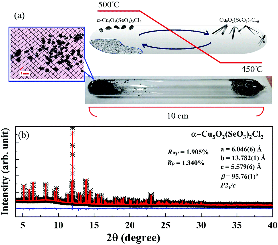
Single crystals of α-Cu5O2(SeO3)2Cl2 were grown using a standard chemical vapor transport phase method. High-purity CuO (Alfa-Aesar, 99.995%), CuCl2 (Alfa-Aesar, 99.995%), and SeO2 (Alfa-Aesar, 99.999%) powders in a molar ratio of 3![[thin space (1/6-em)]](https://www.rsc.org/images/entities/char_2009.gif) :2:2 were mixed under Ar atmosphere. A 15 g sample was loaded into a quartz ampule with 100 mm length and 15 mm diameter. The ampule was horizontally placed in a tubular two-zone furnace and then heated at a rate of 0.5 °C min−1. As shown in Fig. 1(a), for the growth of α-Cu5O2(SeO3)2Cl2 single crystals, the optimum temperatures at the source and deposition zones were set to 500 °C and 450 °C, respectively, for 15 days. Subsequently, the temperature was reduced to room temperature at a rate of 0.5 °C min−1. Several brownish-colored α-Cu5O2(SeO3)2Cl2 single crystals, along with an unidentified powder residue, appeared in the hot zone; α-Cu5O2(SeO3)2Cl2 single crystals were selected on the basis of their color and appearance. Green, thin, platelet-like, Cu9O2(SeO3)4Cl6 single crystals (2–3 mm in length) were formed at the cold end. Electron probe microanalysis (EPMA) [shown in Fig. S1 and Table S1, ESI†] revealed that the stoichiometry of all the heavy elements in the synthesized products was similar to that expected in α-Cu5O2(SeO3)2Cl2.
:2:2 were mixed under Ar atmosphere. A 15 g sample was loaded into a quartz ampule with 100 mm length and 15 mm diameter. The ampule was horizontally placed in a tubular two-zone furnace and then heated at a rate of 0.5 °C min−1. As shown in Fig. 1(a), for the growth of α-Cu5O2(SeO3)2Cl2 single crystals, the optimum temperatures at the source and deposition zones were set to 500 °C and 450 °C, respectively, for 15 days. Subsequently, the temperature was reduced to room temperature at a rate of 0.5 °C min−1. Several brownish-colored α-Cu5O2(SeO3)2Cl2 single crystals, along with an unidentified powder residue, appeared in the hot zone; α-Cu5O2(SeO3)2Cl2 single crystals were selected on the basis of their color and appearance. Green, thin, platelet-like, Cu9O2(SeO3)4Cl6 single crystals (2–3 mm in length) were formed at the cold end. Electron probe microanalysis (EPMA) [shown in Fig. S1 and Table S1, ESI†] revealed that the stoichiometry of all the heavy elements in the synthesized products was similar to that expected in α-Cu5O2(SeO3)2Cl2.
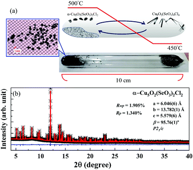 |
| | Fig. 1 (a) Experimental two-zone growth of α-Cu5O2(SeO3)2Cl2 single crystals; pictorial representation of quartz ampoule and a photograph of the real quartz ampoule. Red line in the figure denotes the temperatures of the two-zone furnace's hot and cold ends. Brownish α-Cu5O2(SeO3)2Cl2 and green Cu9O2(SeO3)4Cl6 single crystals grown at the hot and cold ends, respectively, are shown in (a). Light microscopic images of grown α-Cu5O2(SeO3)2Cl2 single crystals at quartz ampoule hot zone. (b) High-resolution synchrotron X-ray diffraction data along with Rietveld refinement of α-Cu5O2(SeO3)2Cl2 at 300 K. | |
2.2 Characterization
The quality of the grown α-Cu5O2(SeO3)2Cl2 single crystals was determined by high-resolution synchrotron X-ray diffraction (SXRD) using the TPS 09A beamline of the Taiwan Photon Source at the National Synchrotron Radiation Research Center. For the SXRD measurements, single crystals were ground to a fine powder. A closed-cycle cryostat was used to control the temperature during the measurements. The samples were mounted on a glass tube, and data were collected in reflection geometry using a wavelength of λ = 0.61922 Å with a double crystal monochromator Si(111) with an energy resolution of 1.33 × 10⁻⁴. Diffraction data were collected at 2°–120° at intervals of 0.004°. Rietveld refinement was performed using the FullProf suite software. The crystal structure was drawn using the VESTA software (version 3.5.2). DC magnetic measurements were conducted using a Quantum Design magnetic property measurement system (MPMS-XL7). Temperature-dependent specific heat C(T) measurements were performed on a plate-like single crystal using a heat-pulsed thermal relaxation calorimeter in the temperature range of 2–300 K and in magnetic fields of up to H = 9 T. Neutron powder diffraction measurements were performed on a high-intensity powder diffractometer WOMBAT,42 and a cold neutron triple-axis spectrometer SIKA at the Bragg Institute, ANSTO. Diffraction measurements were performed on the WOMBAT diffractometer using an incident wavelength of λ = 4.78 Å (3.58 meV) defined by pyrolytic graphite (PG)(002) crystals at the monochromator position, with a take-off angle of 90°. SIKA was operated in the diffraction mode, where the energy of the neutrons was defined by PG(002) crystals at both the monochromator and analyzer positions using fixed final energy of 3 meV, and a Be filter was used to suppress the higher-order contaminations. For the neutron diffraction measurements, approximately 2 g of the powdered sample was loaded into an aluminum sample holder filled with helium gas to facilitate thermal conduction. The sample temperature was controlled using a closed-cycle cryocooler, operating between 3 and 60 K. To investigate the dielectric properties of α-Cu5O2(SeO3)2Cl2, a single crystal measuring ∼2 mm was selected. Silver paint was employed as electrodes on both sides of the crystal to form a parallel-plate capacitor. Dielectric (ε′) measurements were performed using an Agilent E4980A precision LCR meter with an excitation voltage of 5 V. High-temperature ε′ measurements were performed using a closed-cycle cryostat. For magnetodielectric (MD) and pyrocurrent measurements, a homemade sample probe was inserted into the Quantum design MPMS system.
3. Results and discussion
3.1 Structural analysis
High-resolution SXRD is effective for investigating minute secondary phases. As shown in Fig. 1(b), all the reflections in the SXRD pattern collected at room temperature were assigned to the α-Cu5O2(SeO3)2Cl2 phase without any secondary phase. The Rietveld refinement of the high-resolution SXRD data confirmed a monoclinic crystal structure with the space group P21/c. The obtained refinement parameters and unit cell parameters (see Table 2), were consistent with those in previous studies.12,40
Table 2 Lattice parameters, atomic positions, and reliability factors of α-Cu5O2(SeO3)2Cl2 at T = 300 K obtained by assuming space group P21/c
|
a = 6.04667 (5) Å, b = 13.78221 (8) Å, c = 5.57936 (3) Å, β = 95.7620 (6)° |
| Atom |
x
|
y
|
z
|
B
iso (Å2) |
Occupancy |
|
χ
2 = 6.04, Rp = 1.34%, wRp = 1.905%. |
| Cu1 |
0.4343(5) |
0.1900(1) |
0.5553(7) |
0.219 |
1 |
| Cu2 |
0.5000(0) |
0.0000(0) |
1.0000(0) |
0.256 |
1 |
| Cu3 |
0.2572(4) |
−0.0035(9) |
0.4859(4) |
0.259 |
1 |
| Se |
0.0624(2) |
0.1351(4) |
0.8980(5) |
0.444 |
1 |
| O1 |
0.5037(5) |
0.0632(4) |
0.6795(2) |
0.545 |
1 |
| O2 |
0.2230(4) |
0.0583(3) |
1.0073(5) |
0.152 |
1 |
| O3 |
0.0391(7) |
0.0654(4) |
0.6390(4) |
1.101 |
1 |
| O4 |
0.2520(6) |
0.2194(1) |
0.8083(5) |
2.485 |
1 |
| Cl |
0.6712(1) |
0.1760(6) |
0.2703(3) |
2.475 |
1 |
The crystal structure drawn from the output files of the SXRD refinement using the VESTA software are shown in Fig. 2, with a description of the Cu ions in the polyhedral representation. The monoclinic α-Cu5O2(SeO3)2Cl2 unit cell comprised three different Cu atoms, situated in polyhedra formed by the combination of Cl and O anions. In the a–c plane [see Fig. 2(a)], the Cu2O4Cl2 and Cu3O5Cl octahedra formed alternating layers along the a-axis connected via the sharing of octahedral edges. The Cu2 has a square Cu2O4 basal plane with Cu–O bond distances ranging from 1.945 to 1.991 Å, whereas the two Cl atoms were located at the apex with a longer bonding distance of 2.986 Å. This significant difference between the atomic lengths of the basal and apex axes was due to the Jahn–Teller distortion of the Cu2+ ions.41 The Cu3 octahedron was formed by the Cu3O4 basal plane (basal Cu3–O distance of 1.898–2.043 Å) along the distorted apex axes, one O (Cu3–O distance of 2.423 Å), and one Cl (Cu3–Cl distance of 2.751 Å) ions.
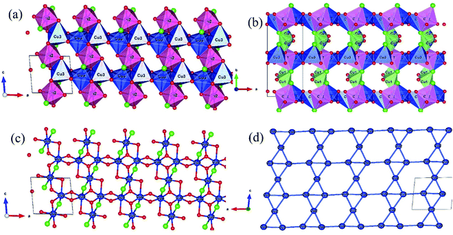 |
| | Fig. 2 Crystal structure of α-Cu5O2(SeO3)2Cl2 single crystal in different directions (a) a–c plane; (b) a–b plane. Cu2 and Cu3 atoms occupied the octahedral and Cu1 occupied square pyramid coordination; for clarity, Se atoms are omitted from the figures. Cu3O5Cl, Cu2O4Cl2, and Cu3O3Cl2 formed blue, pink, and green polyhedra, respectively; a–c plane (c) without polyhedral and (d) only Cu atoms; a bow-tie lattice formed by Cu2 and Cu3 atoms in a–c plane. | |
The alternating a–c planes [see Fig. 2(b)] were linked along the b-axis via two edges of the Cu1O3Cl2 square pyramid polyhedral with a Cu1O3Cl square base (Cu1–O distance of 1.912–2.09 Å and Cu1–Cl distance of 2.253 Å) and one Cl atom (Cu1–Cl distance of 2.560 Å) at the apex point. The Se atoms formed a one-sided three-fold coordination polyhedral connecting to the Cu-polyhedra by corner- and edge-sharing, but were isolated from each other. Fig. 2(c) shows the two-dimensional a–c plane, without a polyhedral representation. The Cu2 and Cu3 atoms linked chains appeared along the a-axis. The edge-sharing Cu3O4 square lattice appeared with alternating long (3.132 Å) and short (2.926 Å) Cu3–Cu3 bond lengths along the a-axis. Fig. 2(d) shows the bonding of Cu atoms in the a–c plane; the Cu atoms form the edge, and corner-sharing distortive alternating triangular and honeycomb lattices called as bow-tie lattice, which can be regarded as between a honeycomb lattice and a Kagomé lattice.43 A similar network of magnetic ions was previously identified in Na2Ni3(OH)2(PO4)2.43 The spins at bow-tie lattice is highly likely to induce spin-frustration in the a–c plane. Furthermore, the alternating Cu3–Cu3 bond lengths along the a-axis may cause the spin structure to become more frustrated.
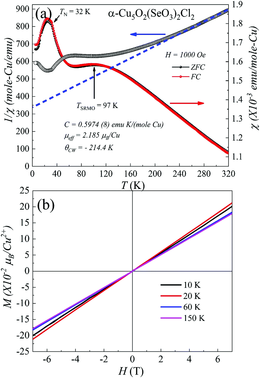
3.2 Magnetic properties
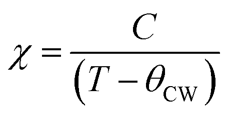
The temperature dependence of the static zero-field cooled (ZFC) and field-cooled (FC) magnetic susceptibility (χ = M/H) for α-Cu5O2(SeO3)2Cl2 in the range 5–320 K with an applied field of 1000 Oe is shown in Fig. 3(a). Owing to the small size and mass of the grown single crystals, magnetic measurements were performed on a collection of several single crystals (approximately 35.5 mg) with random orientations. The ZFC–FC χ versus T curves exhibited almost similar trends down to the lowest temperatures without any irreversibility. The χ versus T curves increased with decreasing temperature and exhibited a broad hump at TSRMO ∼ 97 K; this is characteristic of short-range or low-dimensional magnetic ordering (SRMO) of several low-dimensional magnetic systems.6,29 Although the crystal structure showed the three-dimensional connection of Cu2+ spin 1/2 ions, the presence of an anomaly at TSRMO suggested that the predominant magnetic exchange interactions occur at the two-dimensional a–c plane, where Cu2 and Cu3 spins formed distorted bow-tie lattice. The a–c planes were magnetically connected through a weak exchange interaction. At low temperatures, a kink appeared in the χ versus T curves, indicating long-range antiferromagnetic ordering at TN ∼ 32 K, as verified by the specific heat measurements shown in Fig. 4. The effective paramagnetic moment μeff = √(3kBc/NA) above TSRMO was estimated by fitting the Curie–Weiss (C–W) equation  , where θCW and kB denote the Curie temperature and Boltzmann constant, respectively. The fit of the data to the C–W law in the temperature range of 250–320 K resulted in θCW = −214.4 K and an effective magnetic moment μeff ∼ 2.18 μB. The value of μeff was slightly higher than the expected paramagnetic Cu2+ spin-only value (1.73 μB). This may be due to the estimated μeff is close to TSRMO. A negative θCW indicates a dominantly antiferromagnetic spin-exchange interaction. The spin frustration index was
  , which is close to the frustration index limit
  of typical spin-frustrated systems.44,45
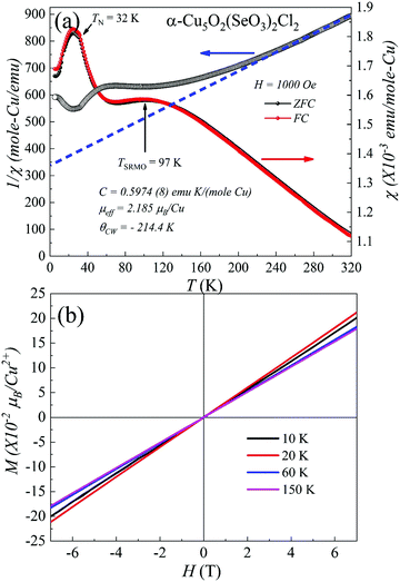 |
| | Fig. 3 (a) Variation in ZFC–FC susceptibility (right y-axis) and inverse susceptibility (left y-axis) of α-Cu5O2(SeO3)2Cl2 single crystal with T in the 5–320 K range. Solid blue line through the inverse susceptibility data denotes the Curie–Weiss fit. (b) Isothermal M vs. H curves for different temperatures. | |
 |
| | Fig. 4 (a) Cpvs. T curve for α-Cu5O2(SeO3)2Cl2 single crystal; inset shows Cpvs. T curves at high temperature; red and green lines indicate slope changes at 230 and 290 K, respectively. (b) Variation in Cp/T vs. T curves under different applied magnetic fields; peaks at TN appeared robust for field up to 9 T. | |
The isothermal magnetization data M(H), are shown in Fig. 4(b). The M versus H curves at different temperatures exhibited linearity without any hysteresis loops. The dM/dH versus H curves (not shown herein) below TN did not exhibit a clear metamagnetic transition within 7 T, signifying the robustness of the antiferromagnetic ground state of α-Cu5O2(SeO3)2Cl2.
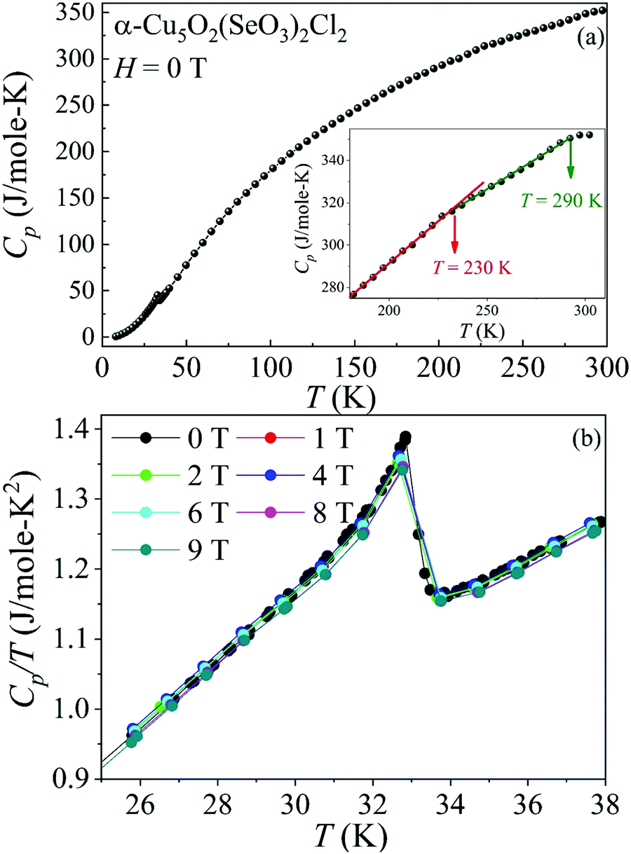
3.3 Specific-heat measurements
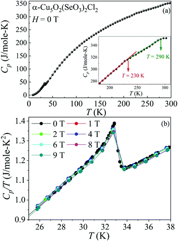
The C(T) of the α-Cu5O2(SeO3)2Cl2 single crystal as a function of temperature is shown in Fig. 4(a). The C(T) exhibits a λ-type peak at 32 K, justifying the assignment of a genuine long-range magnetic order at TN, as shown in Fig. 3(a). Furthermore, a closer observation of the C(T) [see the inset of Fig. 4(a)] at high temperatures revealed clear slope changes at both T = 230 and 280 K. The origin of these signatures in C(T) is closely associated with structural changes, as confirmed by high-resolution synchrotron diffraction and the dielectric constant ε′ [see Fig. 8 and Fig. 9].
Under magnetic fields, interestingly, H has only minimal effects on C(T). For example, the shape of the λ-type peak at TN [see in Fig. 4(b)] did not change with H up to 9 T, indicating the robust nature of this antiferromagnetic order. These results are consistent with the linear M–H curves up to 7 T, as shown in Fig. 3(b). However, a few subtleties may appear in the magnetic properties at H > 7 T. A close analysis revealed that TN increased slightly when H ≥ 8 T compared with at H = 6 T. This transition became even sharper when H ≥ 8 T. Hence, the metamagnetic or other new magnetic states cannot be excluded at high H.
3.4 Low-temperature spin structure
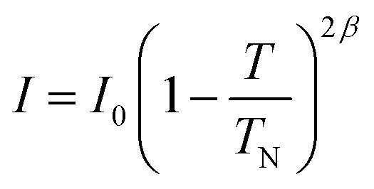
We employed neutron powder diffraction to detect Bragg intensities from magnetic correlations. All the diffraction peaks observed at 60 K can be described using the same monoclinic P21/c crystalline structure obtained from the XRD patterns [see Fig. 1(b)]. Several additional Bragg peaks appeared in the diffraction pattern at 3.5 K. Fig. 5(a) shows the magnetic diffraction pattern at 3.5 K; this was obtained by calculating the difference between the 3.5 and 60 K patterns, in order to isolate the magnetic intensities that developed upon cooling from 60 to 3.5 K. All the magnetic reflections may be indexed using a propagation vector of q = (1/2 0 0), revealing that the magnetic unit cell for the Cu spins is double the nuclear one along the crystallographic a-axis direction. A symmetry analysis based on the BasIreps program yielded four allowed irreducible representations, namely, Γ1, Γ2, Γ3, and Γ4, for the P21/c space group coupled to the (1/2 0 0) propagation vector. A magnetic diffraction pattern was analyzed using the FullProf program,46 in which the P21/c spatial symmetry of the crystalline structure was preserved, as for the magnetic structure. The Γ1 and Γ3 symmetries generated an intensity for the (1/2 0 0) reflection, which is comparable to that of the (1/2 1 1) reflection and zero moment of the Cu2+ ions. The Γ4 symmetry generated a strong intensity for the (1/2 1 0) reflection or required a moment for the Cu3 ions, which was 2.2 times the moment for Cu2+ ions. Γ2 exhibited time reversal in the c-glide plane to generate a magnetic diffraction pattern that best fitted the observed patterns. Fig. 6(a) shows the spin arrangement obtained from the fits to the 3.5 K magnetic pattern, assuming the P21/c spatial symmetry coupled to the Γ2 magnetic symmetry. The magnetic diffraction pattern at 3.5 K can be effectively described [solid line in Fig. 5(a)] using the proposed spin structure shown in Fig. 6(a). The spin arrangement of the Cu2 and Cu3 ions, as shown in Fig. 6(b), can be viewed as the formation of antiferromagnetically coupled ferromagnetic-spin-dimers (dashed rectangular blocks) chains (blue arrows) along the crystallographic a-axis direction, which is separated by antiferromagnetic spin chains (red arrows). Antiferromagnetically coupled ferromagnetic dimers are intriguing. Along with the frustrating nature of the Cu sublattice, these dimers can yield exotic states at extremely low temperatures; this phenomenon deserves further investigation. The Cu1 spins, on the other hand, formed antiferromagnetically coupled ferromagnetic chains along the crystallographic b-axis direction. The magnetic moments and their components along the three crystallographic axis directions of the three distinct Cu ions are presented in Table 3. The antiferromagnetic transition TN was determined by measuring the thermal variations of the (1/2 0 0) intensity I(T), as shown in Fig. 5(b), revealing the variation in the square of the magnetization with temperature. Interestingly, I(T) can be expressed as  , where I0 denotes the saturation magnetic intensity, and β the critical exponent of the magnetic transition, with TN = 32.2(3) K and β = 0.21(2) [solid curve in Fig. 5(b)]. The obtained critical exponent β = 0.21(2) is similar to that of the well-known 2D La0.6Ca0.4MnO3 (β = 0.25) magnet, whereas it is significantly smaller than 0.5, which is anticipated for a three-dimensional magnetic ordering, which signifies dominant magnetic interactions in α-Cu5O2(SeO3)2Cl2 occurring in the 2D plane.47 The TN = 32.2 K obtained from the magnetic diffraction intensity agreed well with the TN values determined from χ(T) [see Fig. 3(a)] and C/T(T) [see Fig. 4(b)].
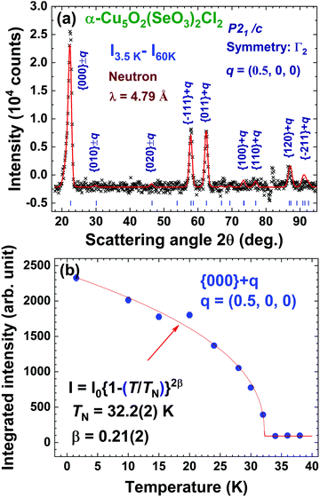 |
| | Fig. 5 (a) Observed (crosses) and calculated (solid lines) neutron magnetic diffraction patterns at 3.5 K, assuming monoclinic P21/c magnetic symmetry for Cu spins. Magnetic reflections are indexed with propagation vector q = (1/2 0 0). Solid vertical lines below the pattern indicate the calculated Bragg positions of the proposed magnetic structure. (b) Temperature dependence of integrated intensity of {000} + q reflection. Solid curve indicates results of data fitted to the expression list in the plot, yielding an antiferromagnetic transition temperature of TN = 32.2(3) K and a critical exponent of β = 0.21(2) for the magnetic transition. | |
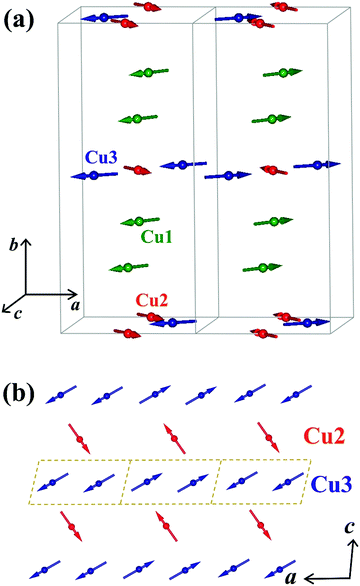 |
| | Fig. 6 Schematic drawing of proposed Cu spin arrangements depicting (a) stacking along crystallographic b-axis direction and (b) projection of Cu2 and Cu3 spins in crystallographic a–c plane. Dashed rectangular blocks indicate ferromagnetic spin-dimers that formed along a-axis direction. Green, red, and blue arrows indicate moments of Cu1, Cu2 and Cu3 respectively. | |
Table 3 Magnetic moments of three crystallographically distinct Cu ions, obtained assuming magnetic space group P21/c, where φ indicates the angle between the moment direction and crystallographic a-axis direction
| Atom |
m
a
(μB) |
m
b
(μB) |
m
c
(μB) |
m (μB) |
φ
|
|
φ = angle between m and a-axis. |
| Cu1 |
−0.48(3) |
0 |
0.54(3) |
0.76(4) |
135° |
| Cu2 |
0.50(3) |
0 |
0.63(4) |
0.76(5) |
55° |
| Cu3 |
−0.63(4) |
0 |
0.37(3) |
0.76(5) |
150° |
3.5 Low-temperature dielectric and magnetodielectric properties
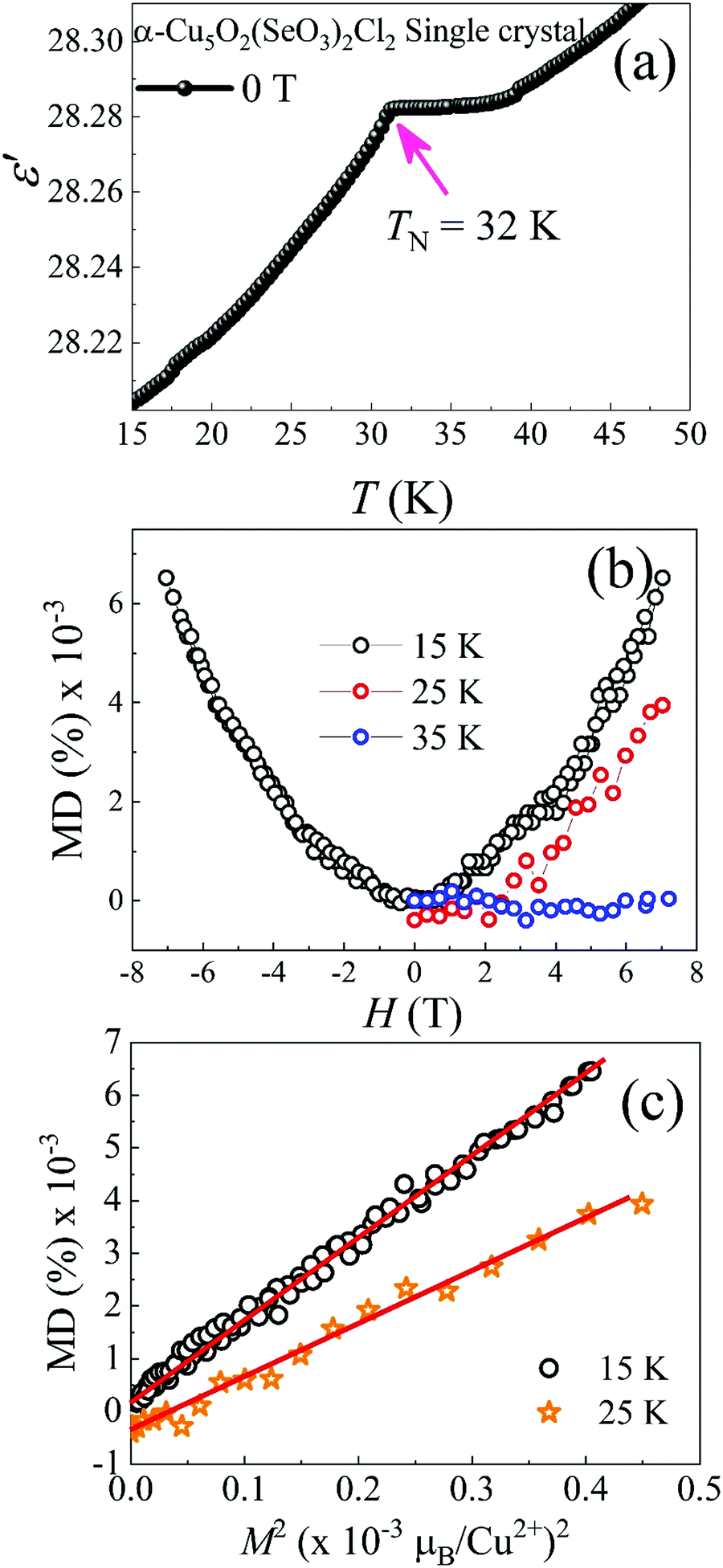
The low temperature ε′ is illustrated in the inset of Fig. 7(a). It exhibited an apparent anomaly near TN. To further investigate the magnetoelectric coupling, an isothermal MD (%) versus H curve at different temperatures was plotted, as shown in Fig. 7(b). A quadratic nature with a maximum MD value of 0.006% at 7 T (15 K) was indicated, and this quadratic nature was valid even at 25 K; this further confirmed the weak magnetoelectric coupling below TN. Above TN, MD was almost absent. The scaling relation of MD (%) ∝ M2 at 15 and 25 K [see Fig. 7(c)] shows magnetoelectric coupling, which was streamed from spin-pair correlation of antiferromagnetic systems below TN.48 Moreover, the dielectric anomaly in the temperature-dependent ε′ for the α-Cu5O2(SeO3)2Cl2 polycrystalline [shown in Fig. S2, ESI†] consistent with the Fig. 7(a). The possible answer for the observed magnetoelectric coupling below TN might be linked to the spin structure. Fig. 6 indicates that the Cu2+ S = 1/2 spins were frustrated at bow-tie lattice in the a–c plane. The cantings of the Cu2 and Cu3 spins in the a–c plane might invoke spin-induced magnetoelectric coupling below TN. Though the centrosymmetric space group down to lowest temperatures usually rules out the crystal symmetry induced magnetoelectric ordering. Furthermore, DM interaction of the form (Si × Sj) will be cancelled out for the spin structure of α-Cu5O2(SeO3)2Cl2 (Fig. 6(a)). However, the possible spin-induced magnetoelectric mechanism might be resulted from the exchange-striction of Cu3 spin chains, the up–up and down–down Cu3 spins along the a-axis might be possible invoke magnetoelectric coupling. The up–up down–down spin structure is a well-known spin arrangement in the field of multiferroics. It has predicted theoretically and proved experimentally in several multiferroic systems that the exchange-striction in this spin configuration can induce electrical polarization.49 The ferrromagnetic spin-dimers along the a-axis direction shown in rectangular block in Fig. 6(b) satisfy the up–up down–down spin structure. To examine the spin-induced electric polarization of α-Cu5O2(SeO3)2Cl2, temperature-dependent pyrocurrent measurements were performed (the data was not shown here) with a poling electric field of E = 0.4 kV mm−1 was applied during the cooling of the sample from T = 60 K (well above the dielectric anomaly TN = 32 K). However, pyrocurrent data doesn’t exhibit a consistent result for different runs, which indicates the present data was not sufficient enough to confirm the electrical ordering. Further studies are needed to give clear picture about the spin-induced electrical ordering, which is out of scope of this paper.
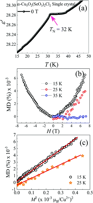 |
| | Fig. 7 (a) ε′ vs. T curves at low temperature (15–40 K) and 1 MHz for α-Cu5O2(SeO3)2Cl2 single crystal for H = 0 T. (b) MD vs. H curves at different temperatures. (c) Shows MD (%) ∝ M2 scaling relation for 15 and 25 K, respectively. | |
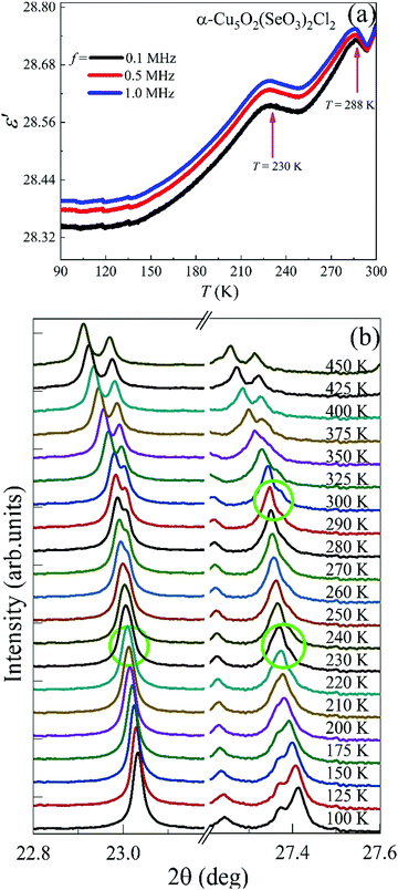
3.6 High-temperature dielectric and SXRD studies
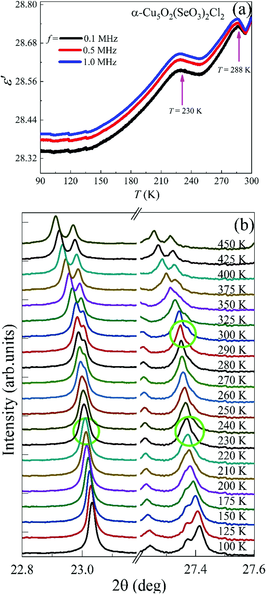
The high-temperature ε′ versus T curves of α-Cu5O2(SeO3)2Cl2 measured at H = 0 [see Fig. 8(a)] showed frequency-independent peaks at T = 288 and 230 K. These two temperatures are closely associated with the weak specific heat anomalies in the upper inset of Fig. 4(a). However, no clear anomalies were observed in the χ versus T curves, indicating that these dielectric transitions were not related to the magnetic origin. To investigate the origin of the specific heat and dielectric anomalies at high temperatures, we employed temperature-dependent SXRD from 450 to 100 K. The SXRD data and Rietveld refinement patterns at 450 and 100 K are shown in Fig. S3 (ESI†). Both the patterns fit well with the P21/c space group, and the obtained refined parameters were satisfactory. The obtained temperature-dependent lattice parameters and the unit cell volume [see Fig. S4, ESI†] further indicated the weak but noticeable anomalies at 230 and 280 K, and these local structural changes were reflected as anomalies in the specific heat [see the inset of Fig. 4(a)] and dielectric measurements. Fig. 8(b) depicts the SXRD patterns (2θ = 22.8°–23.1° and 27.2°–27.6°) in detail clearly, the merging and splitting of the Bragg reflections occurred at approximately 230 and 280 K, respectively.
 |
| | Fig. 8 (a) ε′ vs. T curves at high temperature (90–300 K) for α-Cu5O2(SeO3)2Cl2 single crystals at various frequencies. (b) Temperature dependencies of SXRD patterns for selected 2θ ranges. Peaks merged (at T = 290 K; 2θ = 27.4°–27.6° and at T = 230 K; 2θ = 22.8°–23.2°) and split (at T = 230 K; 2θ = 27.4°–27.6°); the circles indicate the temperature range where the peaks merged. | |
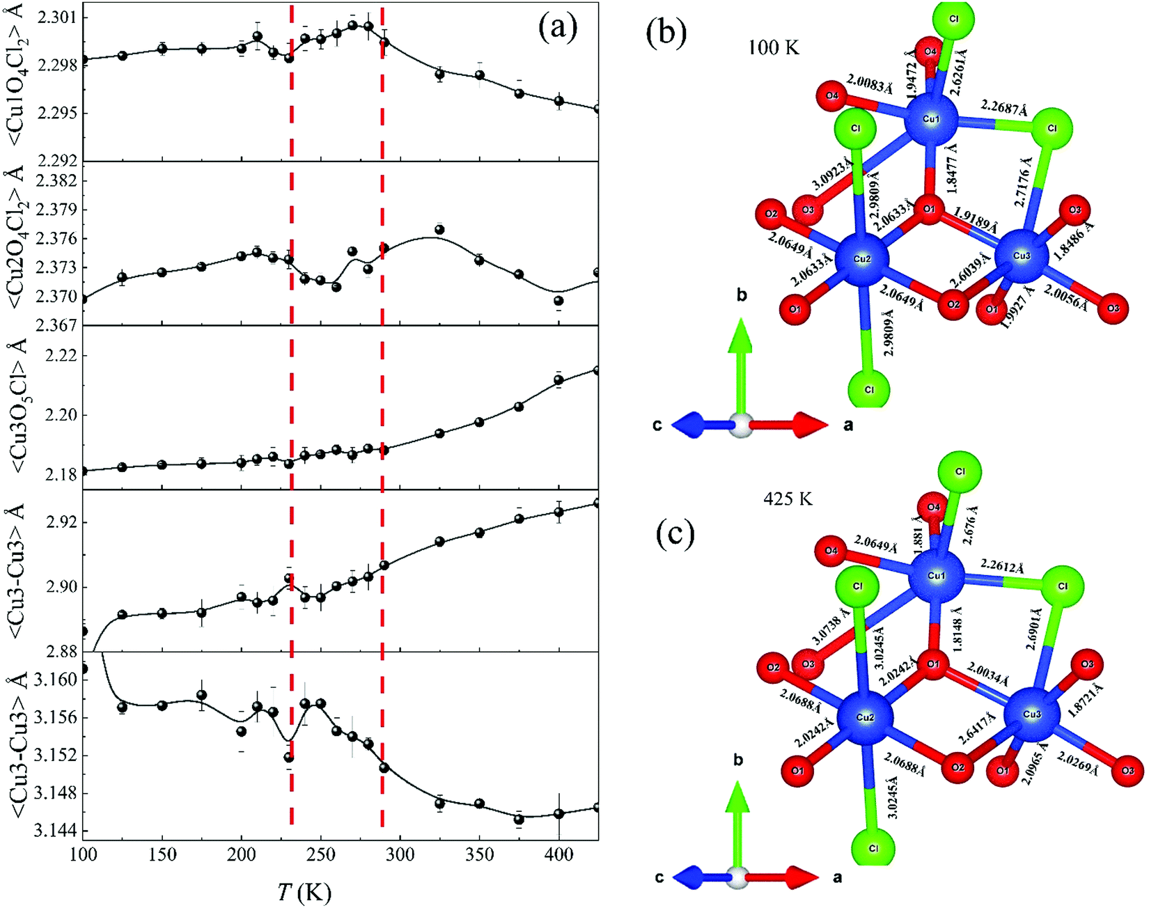
In order to investigate the high-temperature structural change, we have analyzed the detailed structural parameters, such as the temperature-dependent average bond lengths of Cu1 Cu2 and Cu3 polyhedral along with distances within and between the 〈Cu3–Cu3〉 spin-chains. As shown in Fig. 9(a), some clear distortions in the Cu1, Cu2 and Cu3 polyhedral were observed near at 280 K and 230 K. These structural relaxations of Cu polyhedral might trigger the structural transitions at these temperatures. Apart from these, the Cu3 spin-chain along the a-axis showed the changes within the spin-dimer distances and between the spin-dimers. More interestingly, it showed the formation of strong spin-dimers by decreasing the intra spin-dimer and increasing the inter spin-dimer distance as the temperature was lowered.
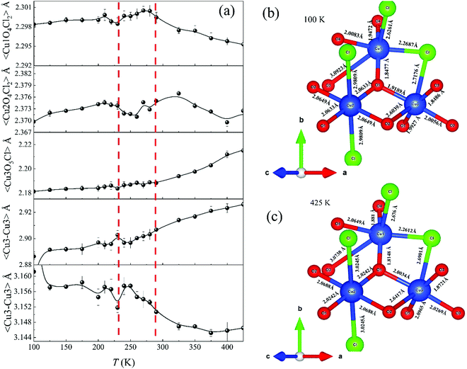 |
| | Fig. 9 (a) The temperature variation of average bond lengths of 〈<Cu1O4Cl2〉, 〈Cu1O4Cl2〉 and 〈Cu3O5Cl〉 polyhedral along with distance within and between the Cu3–Cu3 spin-dimers. (b) and (c) Figures show the Cu polyhedral bonds at 100 and 300 K respectively. | |
The Cu2+ spin-1/2 in Cu-containing oxides exhibits frustrated magnetism, originating either from either the lattice geometry or the dimensional restriction of the magnetic ions. This has resulted in fascinating properties such as multiferroic, magnetoelectric effect and skyrmionic phase.8,24,27–29,31–33,35–37,40,48,50,51 Lone pair Se4+ ions and electron negative halide atoms serve as chemical scissors that can stabilize the low-dimensional magnetic lattice with spin frustration.12 Several compounds in the CuO–CuCl2–SeO2 ternary phase diagram were identified and analyzed (see Table 1). Among them, CuO is known as a type-II multiferroic binary compound that is well established near room temperature.27,32 High-pressure synthesized CuSeO3 exhibited ferromagnetic ordering at TC = 25 K, along with a spin-induced dielectric anomaly in a nonpolar state.48 The most exciting compound, Cu2OSeO3, with a B20 chiral magnetic oxide, exhibited a unique magnetic skyrmion spin.8,30,37 CuCl2 was the first reported nonchalcogen in the multiferroic family, where the Cu2+ spin spiral invoked spin-induced robust multiferroicity at TN = 24 K, even under the significant effect of quantum fluctuation.24 Furthermore, multiferroicity was reported in oxyhalide Cu2OCl2 compounds near the liquid nitrogen temperature,31 where two possible mechanisms, namely spin-induced or charge-transfer-induced multiferroicity, were proposed.31,35 Type-I multiferroic properties have recently been identified in Cu9O2(SeO3)4Cl6 single crystals.36 The α-Cu5O2(SeO3)2Cl2 in this present study is another magnetoelectric member from the CuO–CuCl2–SeO2 phase diagram.
4. Conclusions
We successfully synthesized α-Cu5O2(SeO3)2Cl2 single crystals using the chemical vapor transport method and investigated their structural, magnetic, and dielectric behaviors. The critical findings of this study are as follows: (1) the combined magnetization and specific heat data revealed long-range order at TN = 32 K. (2) The neutron diffraction patterns confirmed antiferromagnetic ordering below TN with complex, anisotropic, and two-dimensional spin structure. (3) The high-resolution SXRD data were consistent with the structural changes, which induced two dielectric peaks at 230 K and 288 K. (4) Observations of weak magnetodielectric effect below TN suggested a possible spin-induced magnetoelectric behavior in α-Cu5O2(SeO3)2Cl2. (5) This study point that the bow-tie lattice of α-Cu5O2(SeO3)2Cl2 is a new spin-frustrated magnetoelectric material.
Author contributions
H. D. Y., D. C. K., and H. C. W. initiated and designed experiments. Z. H. Y., H. C. W., and D. C. K. synthesized single and polycrystalline samples. C. A. L. and M. C. C. provided the experimental facility for single crystal growth and shared the critical knowledge to grow a good quality single crystal. D. C. K., Z. H. Y., and T. W. K. performed structural characterization and sample quality analysis by synchrotron XRD and EPMA measurements. C. K. C. and B. H. C. helped to perform temperature-dependent synchrotron XRD in NSRRC, Taiwan. J. Y. L. and Y. Y. W. performed the heat capacity measurements. W. H. L., C. H. L. and C. W. W. conducted the neutron diffraction measurements and solved low temperature spin structure. D. C. K., H. C. W., Z. H. Y., and A. T. performed magnetic, dielectric, and magnetodielectric measurements. D. C. K. and H. D. Y. wrote the manuscript by integrating input data and analyses provided by all the authors. H. D. Y. and D. C. K. supervised the research.
Conflicts of interest
The authors declare no conflict of interest.
Acknowledgements
This work was supported by the Ministry of Science and Technology, Taiwan, under grant no. MOST 109-2112-M-110-019, MOST 108-2112-M-110-014-MY2, MOST 107-2119-M-009 and MOST 107-2917-I-564-008.
References
- N. A. Spaldin and R. Ramesh, Nat. Mater., 2019, 18, 203–212 CrossRef CAS PubMed.
- Y. Tokura, S. Seki and N. Nagaosa, Rep. Prog. Phys., 2014, 77, 076501 CrossRef PubMed.
- S. W. Huang, D. J. Huang, J. Okamoto, C. Y. Mou, W. B. Wu, K. W. Yeh, C. L. Chen, M. K. Wu, H. C. Hsu, F. C. Chou and C. T. Chen, Phys. Rev. Lett., 2008, 101, 077205 CrossRef CAS PubMed.
- T. Arima, J. Phys. Soc. Jpn., 2011, 80, 052001 CrossRef.
- J. S. Kinyon, R. Clark, N. S. Dalal, E. S. Choi and H. Zhou, Phys. Rev. B: Condens. Matter Mater. Phys., 2015, 92, 144103 CrossRef.
- K. Yoo, B. Koteswararao, J. Kang, A. Shahee, W. Nam, F. F. Balakirev, V. S. Zapf, N. Harrison, A. Guda, N. Ter-Oganessian and K. H. Kim, npj Quantum Mater., 2018, 3, 45 CrossRef.
- K. Kimura, S. Kimura and T. Kimura, J. Phys. Soc. Jpn., 2019, 88, 093707 CrossRef.
- S. Seki, X. Z. Yu, S. Ishiwata and Y. Tokura, Science, 2012, 336, 198 CrossRef CAS PubMed.
- B. Keimer, S. A. Kivelson, M. R. Norman, S. Uchida and J. Zaanen, Nature, 2015, 518, 179–186 CrossRef CAS PubMed.
- X. M. Chen, C. Mazzoli, Y. Cao, V. Thampy, A. M. Barbour, W. Hu, M. Lu, T. A. Assefa, H. Miao, G. Fabbris, G. D. Gu, J. M. Tranquada, M. P. M. Dean, S. B. Wilkins and I. K. Robinson, Nat. Commun., 2019, 10, 1435 CrossRef CAS PubMed.
- D. S. Inosov, Adv. Phys., 2018, 67, 149–252 CrossRef.
- P. S. Berdonosov, E. S. Kuznetsova and V. A. Dolgikh, Crystals, 2018, 8, 159 CrossRef.
- A. Narayan, A. Cano, A. V. Balatsky and N. A. Spaldin, Nat. Mater., 2019, 18, 223–228 CrossRef CAS PubMed.
- B. Koteswararao, K. Yoo, F. C. Chou and K. H. Kim, APL Mater., 2016, 4, 036101 CrossRef.
- J. E. Greedan, J. Mater. Chem., 2001, 11, 37–53 RSC.
- P. Puphal, M. Bolte, D. Sheptyakov, A. Pustogow, K. Kliemt, M. Dressel, M. Baenitz and C. Krellner, J. Mater. Chem. C, 2017, 5, 2629–2635 RSC.
- S.-Y. Zhang, W.-B. Guo, M. Yang, Y.-Y. Tang, M.-Y. Cui, N.-N. Wang and Z.-Z. He, Dalton Trans., 2015, 44, 20562–20567 RSC.
- M. Yang, S.-Y. Zhang, W.-B. Guo, Y.-Y. Tang and Z.-Z. He, Dalton Trans., 2015, 44, 15396–15399 RSC.
- Y. Naito, K. Sato, Y. Yasui, Y. Kobayashi, Y. Kobayashi and M. Sato, J. Phys. Soc. Jpn., 2007, 76, 023708 CrossRef.
- M. Frontzek, J. T. Haraldsen, A. Podlesnyak, M. Matsuda, A. D. Christianson, R. S. Fishman, A. S. Sefat, Y. Qiu, J. R. D. Copley, S. Barilo, S. V. Shiryaev and G. Ehlers, Phys. Rev. B: Condens. Matter Mater. Phys., 2011, 84, 094448 CrossRef.
- N. Reynolds, A. Mannig, H. Luetkens, C. Baines, T. Goko, R. Scheuermann, L. Keller, M. Bartkowiak, A. Fujimura, Y. Yasui, C. Niedermayer and J. S. White, Phys. Rev. B, 2019, 99, 214443 CrossRef CAS.
- J. M. Law, P. Reuvekamp, R. Glaum, C. Lee, J. Kang, M. H. Whangbo and R. K. Kremer, Phys. Rev. B: Condens. Matter Mater. Phys., 2011, 84, 014426 CrossRef.
- L. Zhao, T.-L. Hung, C.-C. Li, Y.-Y. Chen, M.-K. Wu, R. K. Kremer, M. G. Banks, A. Simon, M.-H. Whangbo, C. Lee, J. S. Kim, I. Kim and K. H. Kim, Adv. Mater., 2012, 24, 2469–2473 CrossRef CAS PubMed.
- S. Seki, T. Kurumaji, S. Ishiwata, H. Matsui, H. Murakawa, Y. Tokunaga, Y. Kaneko, T. Hasegawa and Y. Tokura, Phys. Rev. B: Condens. Matter Mater. Phys., 2010, 82, 064424 CrossRef.
- S. V. Krivovichev and L. A. Gorelova, Crystals, 2018, 8, 193 CrossRef.
- H. C. Wu, K. D. Chandrasekhar, J. K. Yuan, J. R. Huang, J. Y. Lin, H. Berger and H. D. Yang, Phys. Rev. B, 2017, 95, 125121 CrossRef.
- T. Kimura, Y. Sekio, H. Nakamura, T. Siegrist and A. P. Ramirez, Nat. Mater., 2008, 7, 291–294 CrossRef CAS PubMed.
- M. Herak, A. Zorko, D. Arčon, A. Potočnik, M. Klanjšek, J. van Tol, A. Ozarowski and H. Berger, Phys. Rev. B: Condens. Matter Mater. Phys., 2011, 84, 184436 CrossRef.
- M. Herak, A. Zorko, M. Pregelj, O. Zaharko, G. Posnjak, Z. Jagličić, A. Potočnik, H. Luetkens, J. van Tol, A. Ozarowski, H. Berger and D. Arčon, Phys. Rev. B: Condens. Matter Mater. Phys., 2013, 87, 104413 CrossRef.
- H. C. Wu, T. Y. Wei, K. D. Chandrasekhar, T. Y. Chen, H. Berger and H. D. Yang, Sci. Rep., 2015, 5, 13579 CrossRef CAS PubMed.
- L. Zhao, M. T. Fernández-Díaz, L. H. Tjeng and A. C. Komarek, Sci. Adv., 2016, 2, e1600353 CrossRef PubMed.
- Z. Wang, N. Qureshi, S. Yasin, A. Mukhin, E. Ressouche, S. Zherlitsyn, Y. Skourski, J. Geshev, V. Ivanov, M. Gospodinov and V. Skumryev, Nat. Commun., 2016, 7, 10295 CrossRef CAS PubMed.
- S. Lee, W. J. Lee, J. van Tol, P. L. Kuhns, A. P. Reyes, H. Berger and K. Y. Choi, Phys. Rev. B, 2017, 95, 054405 CrossRef.
- H. Guo, L. Zhao, W. Schmidt, M. T. Fernández-Díaz, C. Becker, A. Melendez-Sans, W. Peng, M. Zbiri, P. Hansmann and A. C. Komarek, Phys. Rev. Mater., 2019, 3, 124405 CrossRef CAS.
- H. C. Wu, J. K. Yuan, K. D. Chandrasekhar, C. H. Lee, W. H. Li, C. W. Wang, J. M. Chen, J. Y. Lin, H. Berger, T. W. Yen, S. M. Huang, C. W. Chu and H. D. Yang, Mater. Today Phys., 2019, 8, 34–42 CrossRef.
- H. C. Wu, K. N. Denisova, D. Menzel, D. C. Kakarla, O. V. Maximova, T. W. Kuo, Z. H. Yang, C. H. Lee, W. H. Li, H. Berger, C. W. Wang, C. K. Chang, Y. C. Chuang, J. Y. Lin, M. Gooch, C. W. Chu, A. N. Vasiliev and H. D. Yang, Phys. Rev. B, 2019, 100, 245119 CrossRef CAS.
- L. Deng, H.-C. Wu, A. P. Litvinchuk, N. F. Q. Yuan, J.-J. Lee, R. Dahal, H. Berger, H.-D. Yang and C.-W. Chu, Proc. Natl. Acad. Sci. U. S. A., 2020, 117, 8783 CrossRef CAS PubMed.
- K. D. Chandrasekhar, H. C. Wu, C. L. Huang and H. D. Yang, J. Mater. Chem. C, 2016, 4, 5270–5274 RSC.
- L. P. Vergasova, S. V. Krivovichev, S. K. Filatov, S. N. Britvin, P. C. Burns and V. V. Anan’ev, Geol. Ore Deposits, 2007, 49, 518–521 CrossRef.
- S. V. Krivovichev, R. R. Shuvalov, T. E. Semenova and S. K. Filatov, Z. Kristall., 1999, 214, 135–138 CAS.
- J. Galy, J. J. Bonnet and S. Andersson, Acta Chem. Scand., 1979, 33, 383–389 CrossRef.
- A. J. Studer, M. E. Hagen and T. J. Noakes, Phys. B, 2006, 385, 1013–1015 CrossRef.
- O. Yakubovich, G. Kiriukhina, O. Dimitrova, A. Volkov, A. Golovanov, O. Volkova, E. Zvereva, S. Baidya, T. Saha-Dasgupta and A. Vasiliev, Dalton Trans., 2013, 42, 14718–14725 RSC.
- S. E. Dutton, Q. Huang, O. Tchernyshyov, C. L. Broholm and R. J. Cava, Phys. Rev. B: Condens. Matter Mater. Phys., 2011, 83, 064407 CrossRef.
- K. Devi Chandrasekhar, J. Krishna Murthy, J. Y. Lin, H. C. Wu, W. J. Tseng, A. Venimadhav and H. D. Yang, Phys. Rev. B, 2016, 94, 205143 CrossRef.
- J. Rodríguez-Carvajal, Phys. B, 1993, 192, 55–69 CrossRef.
- D. Kim, B. Revaz, B. L. Zink, F. Hellman, J. J. Rhyne and J. F. Mitchell, Phys. Rev. Lett., 2002, 89, 227202 CrossRef CAS PubMed.
- G. Lawes, A. P. Ramirez, C. M. Varma and M. A. Subramanian, Phys. Rev. Lett., 2003, 91, 257208 CrossRef CAS PubMed.
- S. Picozzi, K. Yamauchi, B. Sanyal, I. A. Sergienko and E. Dagotto, Phys. Rev. Lett., 2007, 99, 227201 CrossRef CAS PubMed.
- S. V. Krivovichev, S. K. Filatov, P. C. Burns and L. P. Vergasova, Can. Mineral., 2007, 45, 929–934 CrossRef CAS.
- P. Millet, B. Bastide and M. Johnsson, Solid State Commun., 2000, 113, 719–723 CrossRef CAS.
Footnote |
| † Electronic supplementary information (ESI) available. See DOI: 10.1039/d1ma00526j |
|
| This journal is © The Royal Society of Chemistry 2021 |
Click here to see how this site uses Cookies. View our privacy policy here. 
 Open Access Article
 This Open Access Article is licensed under a
  *ab,
Z. H.
Yang
a,
H. C.
Wu
a,
T. W.
Kuo
a,
Ajay
Tiwari
a,
W.-H.
Li
c,
C. H.
Lee
c,
Y.-Y.
Wang
d,
J.-Y.
Lin
de,
C. K.
Chang
f,
B. H.
Chen
f,
Chin-Wei
Wang
*ab,
Z. H.
Yang
a,
H. C.
Wu
a,
T. W.
Kuo
a,
Ajay
Tiwari
a,
W.-H.
Li
c,
C. H.
Lee
c,
Y.-Y.
Wang
d,
J.-Y.
Lin
de,
C. K.
Chang
f,
B. H.
Chen
f,
Chin-Wei
Wang

 , where θCW and kB denote the Curie temperature and Boltzmann constant, respectively. The fit of the data to the C–W law in the temperature range of 250–320 K resulted in θCW = −214.4 K and an effective magnetic moment μeff ∼ 2.18 μB. The value of μeff was slightly higher than the expected paramagnetic Cu2+ spin-only value (1.73 μB). This may be due to the estimated μeff is close to TSRMO. A negative θCW indicates a dominantly antiferromagnetic spin-exchange interaction. The spin frustration index was
 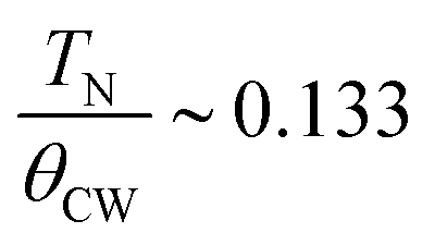 , which is close to the frustration index limit
 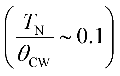 of typical spin-frustrated systems.44,45
 , where I0 denotes the saturation magnetic intensity, and β the critical exponent of the magnetic transition, with TN = 32.2(3) K and β = 0.21(2) [solid curve in Fig. 5(b)]. The obtained critical exponent β = 0.21(2) is similar to that of the well-known 2D La0.6Ca0.4MnO3 (β = 0.25) magnet, whereas it is significantly smaller than 0.5, which is anticipated for a three-dimensional magnetic ordering, which signifies dominant magnetic interactions in α-Cu5O2(SeO3)2Cl2 occurring in the 2D plane.47 The TN = 32.2 K obtained from the magnetic diffraction intensity agreed well with the TN values determined from χ(T) [see Fig. 3(a)] and C/T(T) [see Fig. 4(b)].