 Open Access Article
A substrate surface alloy strategy for integrated sulfide electrodes for sodium ion batteries with superior lifespan†
Li-Feng
Zhou
a,
Tao
Du
 *a,
Li-Ying
Liu
a,
Yi-Song
Wang
a and
Wen-Bin
Luo
 *ab
*ab
aState Environmental Protection Key Laboratory of Eco-Industry, Northeastern University, Shenyang 110004, China. E-mail: luowenbin@smm.neu.edu.cn
bInstitute for Energy Electrochemistry and Urban Mines Metallurgy, School of Metallurgy, Northeastern University, Shenyang, China
First published on 17th June 2021
Abstract
A binder-free free-standing sulfide electrode was synthesized and fabricated with a three dimensional (3D) porous nanostructure. In order to strengthen the adhesion between the substrate and active materials, the surface of the employed nickel foam substrate was modified by an alloy strategy of pre-planting copper seeds onto the nickel foam surface. The obtained electrode presents excellent electrochemical performance in sodium-ion batteries. It delivers a high reversible specific capacity of 1107 mA h g−1 at 0.1 A g−1 with an initial coulombic efficiency of 85.6%. Excellent rate and cycle performances were also exhibited. Even at 2 A g−1, it still can deliver a capacity of 475 mA h g−1. The capacity retention is 61.8% after 1000 cycles at 0.5 A g−1.
Introduction
Sodium-ion batteries (SIBs) are being rapidly developed because they are considered as one of the most promising candidates to replace lithium ion batteries (LIBs) based on their inherent merits of abundant and economically efficient renewable resources.1–5 Over the course of long-term global research, there are many achievements based on the potential material exploration and modification. Industrial SIB prototypes have been created and researchers have started to experiment with potential applications. Several issues have appeared during the trial period.6–12 Among these is the significant issue of unsatisfactory cycling lifespan. To address this issue, two dimensional transition metal dichalcogenides (TMDs), such as MoS2,13,14 TiS2,15,16 TaS2,17 WS2,18,19 MoSe2,20,21 and WSe2,22,23 are attracting increasing attention and widely employed as active materials owing to their overwhelming advantages such as large interlayer spacing and high reversible conversion efficiency. The inherent semiconductor property, however, slows the reaction kinetics resulting from the unsatisfactory electronic conductivity. This sluggish reaction kinetic rate will influence the electrochemical performance, particularly the rate performance.24–26 Therefore, much effort have been made to realize high rate capability and satisfactory lifespan by accelerating the electronic conductivity, such as employing high electronic conductive substrates and designing appropriate morphology. For example, three-dimensional porous-structured substrates, such as graphene or metal foam, are widely utilised owing to their high conductivity and porous structure.27–29 Among them, nickel foams (Ni) have always received increasing attention because of their high economic efficiency and mature practical product. Therefore, various active materials are deposited on the surface of Ni foams to realize an integrated electrode for battery application, particularly binder-free free-standing structure. However, owing to the weak adhesion between the substrate and deposited active materials, the active materials are easily peeled off from Ni foam during the long-term cycling period, thus dramatically decreasing the cycling lifespan.30–32Herein, the surface of a Ni foam was modified by an alloy strategy of pre-planting copper seeds on the nickel foam surface to strengthen the adhesion between the substrate and active materials. First, a NiCu alloy thin layer was formed on the surface of Ni foam and Ni–Cu sulfide (NCS) nanosheets were in situ growing to form a porous flower-like architecture. It was used as a binder-free and free-standing electrode for a sodium ion battery. This architecture has also made great contribution to the enhanced electrochemical performance by the inherent advantages of shorter paths for ion insertion and extraction, larger contact area for more sodium diffusion pathways and superior electrolyte penetration. The as-prepared 3D-structured electrodes exhibit a high specific capacity of 1107 mA h g−1 with an initial coulombic efficiency of 85.6%. It also presents superior rate performance, even at the current density of 2 A g−1, delivering a capacity of 475 mA h g−1. It also exhibited excellent cycle lifespan with 61.8% capacity retention after 1000 cycles at 0.5 A g−1.
Results and discussion
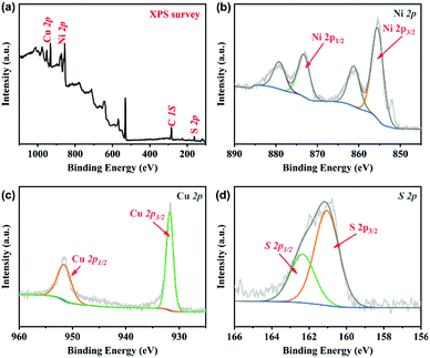
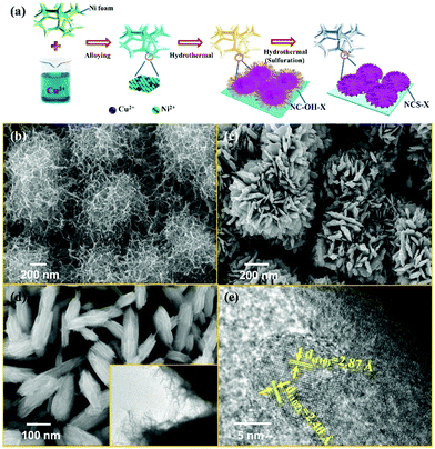
The experimental schematic is described, as shown in Fig. 1a. First, the surface of Ni foam was modified by the alloy technology and a thin layer of the NiCu alloy was obtained. Second, Ni–Cu hydroxide precursors were in situ grown on the surface of the NiCu alloy by a hydrothermal method. Finally, Ni–Cu hydroxide was converted into the corresponding Ni–Cu sulfide (NCS) by further hydrothermal sulfuration reaction. The morphologies of Ni–Cu hydroxide were characterized by field emission scanning electron microscopy (FESEM), as shown in Fig. 1b. The SEM image shows that the Ni–Cu hydroxide on the surface of the Ni foam consists of numerous one-dimensional twisted nanowires, with a diameter of about 10 nm. After the sulfuration reaction, the obtained NCS shows a highly uniform flower-like structure with a size of about 1 μm, as shown in Fig. 1(c–e), composed of numerous nanosheets (Fig. 1d). The transmission electron microscopy (TEM) image (the inset of Fig. 1d) further confirms a slim floc-like morphology on the surface of nanosheets. In areas of the nanosheets in Fig. 1e, clear lattice stripes with different interplanar distances of 2.87 Å and 2.40 Å are observed, which correspond to the (110) and (102) planes of the hexagonal phase structure. In Fig. S1 (ESI†), the strong and sharp peaks at 44.6°, 52.0° and 76.6° (JCPDS, 70-1849) can be assigned to the Ni foam substrate. Several representative peaks can be attributed to the Ni–Cu sulfide materials.The chemical state and elemental composition of NCS is further characterized by X-ray photoelectron spectroscopy (XPS). The existence of Cu, Ni, O, C and S is proved in the survey spectrum33–36 (Fig. 2a). With C 1s (284.6 eV) as the reference, Ni 2p, Cu 2p and S 2p XPS peak-fitting results of NCS are shown in Fig. 2(b–d), respectively. In the Ni 2p spectrum, two main peaks at 873.6 and 855.8 eV could be assigned to Ni 2p1/2 and Ni 2p3/2, respectively, and the other two peaks correspond to the accompanied satellite peaks of Ni 2p1/2 and Ni 2p3/2. In the Cu high-resolution XPS, the peaks at 951.6 and 931.8 eV correspond to 2p3/2 and 2p1/2 of Cu. For S 2p, the peaks at 162.1 eV and 160.9 eV originate from S 2p1/2 and S 2p3/2, respectively. Nitrogen adsorption–desorption isotherm measurements were conducted to examine the porous nature of the NCS composite. The profile of the N2 isotherms in Fig. S2 (ESI†) is identified as type-IV with a small hysteresis loop, confirming the existence of a mesoporous structure. The isotherms are characteristic of micropore filling in the low-pressure region and display a mild adsorption in the high-pressure region, indicating that both micropore and mesopore filling occurred and the amount is very small. The Brunauer–Emmett–Teller specific surface area of the composite is 94.5 m2 g−1, and the total pore volume is 0.179 mL g−1 (Fig. S3, ESI†). The average pore size of the multilevel pore structure is 7.4 nm. The mesopores have a favourable effect on the transport of electrolyte ions.
 | ||
| Fig. 2 XPS spectroscopy of (a) survey spectrum and high-resolution scans of (b) Ni 2p, (c) Cu 2p, and (d) S 2p. | ||
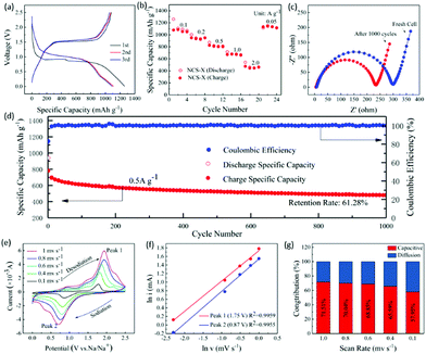
To evaluate the electrochemical performance of NCS, two-electrode configuration was applied using sodium metal as the reference and counter electrode and binder-free NCS as the anode material (Fig. 3 and Fig. S4, ESI†). The charge/discharge profiles and CV curves could effectively elucidate the oxidation/reduction of the sodium storage process. The initial three charge and discharge curves of NCS are shown in Fig. 3a. The voltage plateaus near 0.9 V in the first discharge process could be attributed to the conversion reaction in which sulfide converted into Ni, Cu particles, accompanied by the formation of a solid electrolyte layer (SEI). In addition, the high rate capability of such electrodes is presented in Fig. 3b. It delivers reversible specific capacities of 1050, 949, 802, 662, 461 mA h g−1 at 0.1, 0.2, 0.5, 1.0 and 2.0 A g−1, respectively. When the current density was back to 0.05 A g−1, a highly stable capacity of 1117 mA h g−1 was resumed for the NCS electrode, indicating good cycling stability and rapid reaction kinetics, which is ascribed to the well-dispersed and highly conductive NCS electrode. The improved electrochemical properties are related to the internal resistance of the electrode, including bulk impedance and interfacial impedance. Before and after cycling, the Nyquist plots were collected (Fig. 3c). The compressed semicircle in the high/middle-frequency region represents charge-transfer resistance (Rct) at the interface of the composite. Further, the oblique straight line in the low-frequency region corresponds to ion diffusion, which stands for the Warburg impendence (Zw).37 After cycles, the Rct decreases apparently, indicating improved interfacial wettability and sodium ion diffusion with cycling. It further reveals that the cell with the NCS interlayer possesses good electrochemical kinetics, which reflects the good cycle performance of the cell. In addition, the slope in the low frequency range is same. These interconnected nanosheets with high conductivity are beneficial for fast electron transport during the electrochemical process. Fig. 3d shows the cycle performance and corresponding coulombic efficiency of NCS at 0.5 A g−1. It could deliver a discharge capacity of 940 mA h g−1, and a charge capacity of 478 mA h g−1 can still be achieved after 1000 long cycles and the retention can reach 61.3%. Compared with the previously reported transition-metal dichacolgenide electrodes (Table S1, ESI†), the electrochemical performance of this material is comparable.32–37 The mesoporous nanostructure and large surface area could provide efficient ion and electron transport, resulting in faster kinetics for faradaic energy storage.
To further reveal the electrochemical kinetics of the NCS electrode, cyclic voltammetry (CV) measurements under different scan rates (0.1–1.0 mV s−1) were conducted (Fig. 3e). At 0.1 mV s−1, the CV curve possesses a pair of redox peaks, plots of the cathodic process at ∼0.87 V and the anodic process at ∼1.75 V, which are in accordance with the plateaus of the discharge and charge curves (Fig. 3a). As the scan rate increased, the CV curves display similar shapes with the cathodic and anodic peak potentials gradually shifting towards the positive/negative potential and the redox current increases, indicating diffusion-controlled reaction kinetics. A related analysis can be performed regarding the behaviour of the peak current by assuming that the current (i) obeys a power law relationship with the scan rate (v):38
| i = avb | (1) |
![[thin space (1/6-em)]](https://www.rsc.org/images/entities/char_2009.gif) I vs. ln
I vs. ln![[thin space (1/6-em)]](https://www.rsc.org/images/entities/char_2009.gif) v plots. If b approaches 1, the system is mainly controlled by capacitance. If b is close to 0.5, it represents a diffusion limited process. For simplifying the computation procedure, (1) can be rewritten as:
v plots. If b approaches 1, the system is mainly controlled by capacitance. If b is close to 0.5, it represents a diffusion limited process. For simplifying the computation procedure, (1) can be rewritten as:ln![[thin space (1/6-em)]](https://www.rsc.org/images/entities/char_2009.gif) i = b × ln i = b × ln![[thin space (1/6-em)]](https://www.rsc.org/images/entities/char_2009.gif) v + ln v + ln![[thin space (1/6-em)]](https://www.rsc.org/images/entities/char_2009.gif) a a | (2) |
The relationship of ln![[thin space (1/6-em)]](https://www.rsc.org/images/entities/char_2009.gif) v − ln
v − ln![[thin space (1/6-em)]](https://www.rsc.org/images/entities/char_2009.gif) i is shown in Fig. 3f. Also, the b values at different oxidation and reduction states are 0.75 and 0.71 with R2 up to 0.9955 and 0.9959, respectively. It indicates that the electrochemical reaction of NCS is controlled by the combination of capacitive and diffusion processes. Moreover, the relationship i = avb can be separated into two parts including capacitive (k1v) and diffusion limited effects (k2v1/2), as follows:39–41
i is shown in Fig. 3f. Also, the b values at different oxidation and reduction states are 0.75 and 0.71 with R2 up to 0.9955 and 0.9959, respectively. It indicates that the electrochemical reaction of NCS is controlled by the combination of capacitive and diffusion processes. Moreover, the relationship i = avb can be separated into two parts including capacitive (k1v) and diffusion limited effects (k2v1/2), as follows:39–41
 | (3) |
Here, v is the scan rate, and i is the total current response at a fixed potential (V), which can be separated into two mechanisms. For simplifying the computation procedure, (3) can be rewritten as:
 | (4) |
Calculated and fitted data are illustrated in Fig. S5 (ESI†). For example, approximately 71.5% of the total current comes from capacitive contribution at a scan rate of 1 mV s−1 for NCS. Capacitive-controlled currents predominately concentrated in the peak regions. The remaining regions are almost entirely diffusion controlled, which is in accordance with the result of b-value. Fig. 3g summarizes the contribution of the capacitive behavior under various scan rates. The capacitive contributions are 57.9%, 65.6%, 68.9%, 70.0%, and 71.5% under the scan rates of 0.1, 0.4, 0.6, 0.8, and 1.0 mV s−1, respectively. The kinetic analysis clearly exhibits that the capacitive charge-storage does occupy a high proportion of the total capacity and increases with the increase in the scan rate.
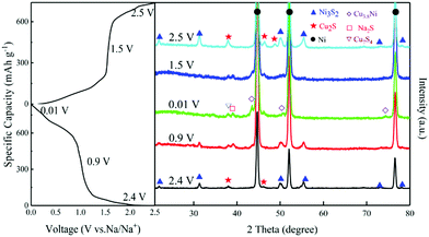
Ex situ XRD tests were carried out to investigate the storage mechanism of NCS electrodes. Fig. 4 shows the XRD patterns of NCS electrodes at different charge–discharge states. At 0.9 V, the peak of Na2S appeared, while the peaks of Ni3S2 and Cu2S gradually disappeared. At 0.01 V, the diffraction peaks of Na2S and Cu3.8Ni alloy are obviously present after discharge. Possible total electrochemical reactions during discharge process are shown below:
| Ni3S2 + 5.7Cu2S + 15.4Na+ + 15.4e− → 7.7 Na2S + 11.4Cu + 3Ni | (5) |
This conjecture matches with the CV curves and typical discharge and charge profiles above. The pattern at 1.5 V still shows the representative peaks of Na2S and the alloy, but the intensity reduced during the charge process.42 The pattern at 2.5 V is almost the same as that of the fresh NCS encouragingly, indicating that a reversible conversion reaction occurs during the first cycle. The possible total desodiation reactions in the charge process are shown below:
| (x + 2)Na2S + 2xCu + 3Ni → Ni3S2 + xCu2S + 2(x + 2)Na+ + 2(x + 2)e− (x < 5.7) | (6) |
Conclusions
A binder-free free-standing structured sulphide electrode was synthesized and fabricated by the hydrothermal method. In order to strengthen the adhesion between the substrate and active materials, the surface of the nickel foam was modified by alloy strategies. The obtained three-dimensional porous-integrated electrode composited by numerous sulfide nanosheets provides much more active sites and the special architecture can also short the diffusion path of the electrolyte and electron during charge and discharge, resulting in faster kinetics for energy storage. It delivers an initial coulombic efficiency of 85.6% with a high reversible specific capacity of 1107 mA h g−1 at 0.1 A g−1. The electrode exhibited excellent cycling performance, with 61.3% retention after 1000 long cycles at 0.5 A g−1.Conflicts of interest
There are no conflicts to declare.Acknowledgements
This work was supported by LiaoNing Revitalization Talents Program (XLYC2007155), the Fundamental Research Funds for the Central Universities (N2025018, N2025009), the National Key Research and Development Project (No. 2019YFC1905200 and 2017YFB0304001), the National Natural Science Foundation of China (No. 51904073), and Fundamental Research Funds for the central Universities (Grants N182508027).References
- A. S. Arico, P. Bruce, B. Scrosati, J. M. Tarascon and W. Van Schalkwijk, Nat. Mater., 2005, 4, 366–377 CrossRef CAS PubMed.
- C. Liu, F. Li, L.-P. Ma and H.-M. Cheng, Adv. Mater., 2010, 22, E28 CrossRef CAS PubMed.
- J. M. Tarascon and M. Armand, Nature, 2001, 414, 359–367 CrossRef CAS PubMed.
- N. Yabuuchi, K. Kubota, M. Dahbi and S. Komaba, Chem. Rev., 2014, 114, 11636–11682 CrossRef CAS PubMed.
- Z. Yan, Q.-W. Yang, Q. Wang and J. Ma, Chin. Chem. Lett., 2020, 31, 583–588 CrossRef CAS.
- M. Yang, Q. Ning, C. Fan and X. Wu, Chin. Chem. Lett., 2021, 32, 895–899 CrossRef CAS.
- H. Huang, X. Luo, Y. Yao, X. Zhou, Y. Jiang, C. Guo, J. Liu, X. Wu and Y. Yu, InfoMat, 2021, 3, 421–431 CrossRef CAS.
- B. Wang, Y. Cheng, H. Su, M. Cheng, Y. Li, H. Geng and Z. Dai, ChemSusChem, 2020, 13, 4078–4085 CrossRef CAS PubMed.
- Y.-Y. Wang, B.-H. Hou, J.-Z. Guo, Q.-L. Ning, W.-L. Pang, J. Wang, C.-L. Lu and X.-L. Wu, Adv. Energy Mater., 2018, 8, 9218–9225 Search PubMed.
- D.-H. Liu, W.-H. Li, Y.-P. Zheng, Z. Cui, X. Yan, D.-S. Liu, J. Wang, Y. Zhang, H.-Y. Lu, F.-Y. Bai, J.-Z. Guo and X.-L. Wu, Adv. Mater., 2018, 30, 1706317 CrossRef PubMed.
- L. Xue, S. V. Savilov, V. V. Lunin and H. Xia, Adv. Funct. Mater., 2018, 28, 1705836 CrossRef.
- L. Xue, Q. Zhang, X. Zhu, L. Gu, J. Yue, Q. Xia, T. Xing, T. Chen, Y. Yao and H. Xia, Nano Energy, 2019, 56, 463–472 CrossRef CAS.
- M. Acerce, D. Voiry and M. Chhowalla, Nat. Nanotechnol., 2015, 10, 313–318 CrossRef CAS PubMed.
- K. Chang and W. Chen, ACS Nano, 2011, 5, 4720–4728 CrossRef CAS PubMed.
- T. Liu, X. Zhang, M. Xia, H. Yu, N. Peng, C. Jiang, M. Shui, Y. Xie, T.-F. Yi and J. Shu, Nano Energy, 2020, 67, 104295 CrossRef CAS.
- J. Tang, X. Huang, T. Lin, T. Qiu, H. Huang, X. Zhu, Q. Gu, B. Luo and L. Wang, Energy Storage Mater., 2020, 26, 550–559 CrossRef.
- Q. Peng, Z. Wang, B. Sa, B. Wu and Z. Sun, ACS Appl. Mater. Interfaces, 2016, 8, 13449–13457 CrossRef CAS PubMed.
- J. Duan, S. Chen, B. A. Chambers, G. G. Andersson and S. Z. Qiao, Adv. Mater., 2015, 27, 4234–4241 CrossRef CAS PubMed.
- T. Lei, W. Chen, J. Huang, C. Yan, H. Sun, C. Wang, W. Zhang, Y. Li and J. Xiong, Adv. Energy Mater., 2017, 7, 1601843 CrossRef.
- F. Niu, J. Yang, N. Wang, D. Zhang, W. Fan, J. Yang and Y. Qian, Adv. Funct. Mater., 2017, 27, 1700522 CrossRef.
- Y. Shi, C. Hua, B. Li, X. Fang, C. Yao, Y. Zhang, Y.-S. Hu, Z. Wang, L. Chen, D. Zhao and G. D. Stucky, Adv. Funct. Mater., 2013, 23, 1832–1838 CrossRef CAS.
- Y. Y. Lee, G. O. Park, Y. S. Choi, J. K. Shon, J. Yoon, K. H. Kim, W.-S. Yoon, H. Kim and J. M. Kim, RSC Adv., 2016, 6, 14253–14260 RSC.
- B. Liu, T. Luo, G. Mu, X. Wang, D. Chen and G. Shen, ACS Nano, 2013, 7, 8051–8058 CrossRef CAS PubMed.
- G. Fang, J. Zhou, A. Pan and S. Liang, ACS Energy Lett., 2018, 3, 2480–2501 CrossRef CAS.
- P. K. Nayak, L. Yang, W. Brehm and P. Adelhelm, Angew. Chem., Int. Ed., 2018, 57, 102–120 CrossRef CAS PubMed.
- J. Pang, R. G. Mendes, A. Bachmatiuk, L. Zhao, H. Q. Ta, T. Gemming, H. Liu, Z. Liu and M. H. Rummeli, Chem. Soc. Rev., 2019, 48, 72–133 RSC.
- D. Aurbach, B. Markovsky, I. Weissman, E. Levi and Y. Ein-Eli, Electrochim. Acta, 1999, 45, 67–86 CrossRef CAS.
- W. Chen, S. Li, C. Chen and L. Yan, Adv. Mater., 2011, 23, 5679 CrossRef CAS PubMed.
- H. Hou, C. E. Banks, M. Jing, Y. Zhang and X. Ji, Adv. Mater., 2015, 27, 7861–7866 CrossRef CAS PubMed.
- Y. Jin, H. Wang, J. Li, X. Yue, Y. Han, P. K. Shen and Y. Cui, Adv. Mater., 2016, 28, 3785–3790 CrossRef CAS PubMed.
- Z. Tang, C.-h. Tang and H. Gong, Adv. Funct. Mater., 2012, 22, 1272–1278 CrossRef CAS.
- C. Yuan, L. Yang, L. Hou, L. Shen, X. Zhang and X. W. Lou, Energy Environ. Sci., 2012, 5, 7883–7887 RSC.
- Y. Lu, B. Li, S. Zheng, Y. Xu, H. Xue and H. Pang, Adv. Funct. Mater., 2017, 27, 1703949 CrossRef.
- S. S. Park, Y. Tulchinsky and M. Dinca, J. Am. Chem. Soc., 2017, 139, 13260–13263 CrossRef CAS PubMed.
- Z. Zheng, H.-H. Wu, H. Chen, Y. Cheng, Q. Zhang, Q. Xie, L. Wang, K. Zhang, M.-S. Wang, D.-L. Peng and X. C. Zeng, Nanoscale, 2018, 10, 22203–22214 RSC.
- W. Zhou, X. Cao, Z. Zeng, W. Shi, Y. Zhu, Q. Yan, H. Liu, J. Wang and H. Zhang, Energy Environ. Sci., 2013, 6, 2216–2221 RSC.
- K. Zeng, X. Li, Z. Wang, H. Guo, J. Wang, T. Li, W. Pan and K. Shih, Electrochim. Acta, 2017, 247, 795–802 CrossRef CAS.
- W. Ren, H. Zhang, C. Guan and C. Cheng, Adv. Funct. Mater., 2017, 27, 1702116 CrossRef.
- R. Sun, S. Liu, Q. Wei, J. Sheng, S. Zhu, Q. An and L. Mai, Small, 2017, 13, 28834239 Search PubMed.
- K. Zhang, M. Park, L. Zhou, G. H. Lee, J. Shin, Z. Hu, S. L. Chou, J. Chen and Y. M. Kang, Angew. Chem., Int. Ed., 2016, 55, 12822–12826 CrossRef CAS PubMed.
- D. Xu, C. Chen, J. Xie, B. Zhang, L. Miao, J. Cai, Y. Huang and L. Zhang, Adv. Energy Mater., 2016, 6, 1501929 CrossRef.
- J. Li, D. Yan, T. Lu, W. Qin, Y. Yao and L. Pan, ACS Appl. Mater. Interfaces, 2017, 9, 2309–2316 CrossRef CAS PubMed.
Footnote |
| † Electronic supplementary information (ESI) available. See DOI: 10.1039/d1ma00363a |
| This journal is © The Royal Society of Chemistry 2021 |


