 Open Access Article
Creative Commons Attribution 3.0 Unported Licence
Hydrophobic and hydrophilic modification of hierarchically porous monolithic polyimide derivatives as functional liquid absorbers†
Yan
Wang
,
Luwei
Zhang
,
Taka-Aki
Asoh
 * and
Hiroshi
Uyama
 *
*
Department of Applied Chemistry, Graduate School of Engineering, Osaka University, 2-1 Yamadaoka, Suita, Osaka, 565-0871, Japan. E-mail: asoh@chem.eng.osaka-u.ac.jp; uyama@chem.eng.osaka-u.ac.jp
First published on 6th April 2021
Abstract
A cost-effective and facile method was developed for the fabrication of two polyimide-based (PI-based) monoliths (pure PI monolith and hybrid PI monolith) with a hierarchically porous structure that avoids the shortcomings of traditional methods. In this case, the thermally induced phase separation (TIPS) method was used to prepare polyamic acid (PAA) monoliths for the first time, then PI-based monoliths were fabricated by thermal imidization. Through the introduction of octakis(glycidyldimethylsiloxy)octasilsesquioxane into the PAA prepared from 4,4′-oxydianiline and pyromellitic dianhydride, both the hydrophobicity and mechanical strengths of the PI-based monoliths were improved. Moreover, the resulting PI-based monoliths exhibited suitable permeability, homogeneous morphologies, and superior thermal stability. Adsorption tests demonstrated that the resulting hybrid PI monoliths exhibited better adsorption performance for organic solvents and silicone oil than the pure PI monolith. Furthermore, the surface of a polyhedral oligomeric silsesquioxane (POSS) hybridized PI (PI-co-POSS) monolith can be modified into a hydrophilic layer by reaction between the hydrophilic polymer and epoxy groups exposed on the surface. This indicates that PI-co-POSS monoliths have potential in liquid diode application to achieve oil–water separation.
Introduction
Since Bogert and Renshaw synthesized aromatic polyimides (PIs) by the self-condensation polymerization of 4-amino-o-phthalic acid in 1908, interest in PIs has been growing steadily owing to their thermo-oxidative stability, unique electrical properties, high radiation and solvent resistance, and high mechanical strength.1–4 For example, PI materials including films and aerogels have been widely applied in a wide range of fields such as semiconductor fabrication,5 microelectronics,6 gas storage,7 and separation.8Among various materials, polymer monoliths as porous materials exhibit many advantages including chemical stability, selectivity, easy modification and mechanical stability.9–11 Because of these characteristics, they are widely applied in the adsorption,12,13 catalysis,14,15 energy storage,16,17 and separation fields.18,19 Therefore, various porous PIs have been reported,20–22 and PI monoliths that enable further functionalization such as improvement of heat resistance, hydrophobicity, and the surface modification ability are required for a wide range of applications in the future.
A polyhedral oligomeric silsesquioxane (POSS) with a cage-like structure is an organic–inorganic hybrid molecule of nanoscale size (1–3 nm). It can be introduced into a reaction system to prepare monolithic materials with good performance because it exhibits distinctive properties, such as thermal performance, dielectric performance, and small-size and macroscopic quantum effects. The skeleton of the POSS molecule is composed of Si–O–Si structural units that endow it with chemical inertness and thermostability. Moreover, there are various substituted POSS reagents containing one or more alkyl, vinyl, epoxy, carboxyl, and methacryloyloxy functional groups. These reactive groups offer reactivity for POSS reagents, which increases the compatibility of POSS with other molecules and polymers. Therefore, the incorporation of POSS reagents into a reaction system not only improves the chemical and physical properties of the polymer but also allows the remaining reactive functional groups to be used to achieve further surface modifications. Therefore, it is necessary to newly design a porous material consisting of PI and POSS units.
In this study, we prepared a POSS hybridized PI (PI-co-POSS) monolith with a co-continuous porous structure. The PI and PI-co-POSS monoliths exhibit a hierarchically porous structure, and the introduction of POSS molecules improves mechanical strength. Because the PI-co-POSS monolith has improved hydrophobicity compared to the PI monolith, it exhibits excellent organic solvent and silicone oil absorption capacity. Furthermore, we found that the surface of the PI-co-POSS monolith can be modified into a hydrophilic layer by reaction between the hydrophilic polymer and epoxy groups exposed on the surface. The overall design, including the chemical composition, skeleton, and surface, can be a new innovation in porous PIs for application in various fields.
Results and discussion
Preparation of monolithic PI and PI-co-POSS materials
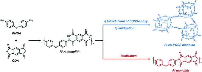
Porous materials can generally be prepared in various ways including phase separation,23 the hard template method,24 the foaming method,25 and the emulsion method.26 For phase separation, thermally induced phase separation (TIPS) and chemically induced phase separation (CIPS), system conditions were changed to reduce the solubility of certain components that led to the aggregation of a new phase from the polymerization solution. When the solvents were removed, a porous monolith was successfully fabricated. In this case, the TIPS approach was applied in the fabrication of porous monolithic polyamic acid-based (PAA-based) materials for the first time. Furthermore, both thermal and chemical methods are usually used to prepare PI. Because the solvent used in the chemical method can destroy the structure of the PAA monolith, the thermal method was chosen to achieve imidization in this study. PI-based monoliths were prepared according to the processes shown in Schemes 1 and 2a.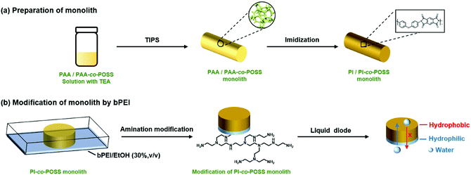 | ||
| Scheme 2 (a) Preparation of PI/PI-co-POSS monoliths via TIPS and thermal imidization. (b) Modification of the PI-co-POSS monolith with bPEI. | ||
The solvent is one of the most important factors affecting the formation of the pore structure and skeleton of the polymeric monolith during phase separation. The PAA solution as a predecessor was synthesized using pyromellitic dianhydride (PMDA) and 4,4′-oxydianiline (ODA) and evenly dissolved in super dehydrated N,N-dimethylformamide (DMF). In this context, DMF was chosen as a good solvent, as it has a high boiling point and is suitable for TIPS during heating. To select a poor solvent, the PAA solution was dropped into various solvents containing acetone, methanol, ethanol, and deionized water, separately. Finally, a mixture of DMF and deionized water was chosen as porogenic solvent for phase separation, because the PAA solution (with DMF as the solvent) could be precipitated immediately in deionized water. The composition of the PAA solution before phase separation is listed in Table 1. The effect of the solvent proportion in monolith formation was investigated first. As presented in Table 1, when the weight percentage of DMF in the mixture was 58.8%, the PAA solution was precipitated in the solvent, and not homogenous even at 80 °C with stirring for a long time and could not form a monolith at low temperature. With increasing DMF content (64.5%), the PAA solution could form monolith 2 by phase separation at 25 °C. However, as the content of DMF increased to 70.6%, phase separation did not occur even at a quite low temperature. This phenomenon illustrated DMF as good solvent and water as poor solvent. Subsequently, the pore morphology of monolith 2 was characterized by SEM; it exhibited a globular and discontinuous pore structure (as shown in Fig. S1a in the ESI†). To obtain a continuous porous structure and a number of through-pores in the monolith, TEA was introduced into the solvent system. Therefore, different amounts of TEA were added to the PAA solution to investigate its influence on the PI monolith. When the amount of TEA was kept at 50 μL, phase separation successfully occurred and the permeability of monolith 4 was 1.03 × 10⁻¹⁴ m2. However, the monolith could not form when the TEA content increased to 100 μL. This was due to the generation of some PAA ammonium salt, which increased the solubility of the polymers in water. Although the PAA solution could undergo phase separation when more deionized water was dropped, the resulting monolith was too soft and easily broken while exchanging solvents. Moreover, a comparison of the SEM images of monoliths 2 (Fig. S1a, ESI†) and 4 (Fig. S1b, ESI†) shows that the globular and discontinuous pore structure disappeared and through-pores appeared in monolith 2, because the mechanism of phase separation might be changed by the addition of TEA.27
| Monolitha | POSS-epoxyb (wt%) | Monomer concentration (mg mL−1) | DMFc (wt%) | H2Oc (wt%) | TEA (μL) | Cooling temperature (°C) | Permeability (×10−14 m2) |
|---|---|---|---|---|---|---|---|
| a The prepolymerization solution also contained 138.1 mg of the monomer ODA and 145.4 mg of PMDA. b Weight percentage of POSS-epoxy in total monomers. c Weight percentage of solvent in the porogenic system mixture. d The prepolymerization solution could not form monoliths. e The prepolymerization solution was not homogeneous. f The monolith did not possess through-pores. | |||||||
| 1 | 0 | 182.9 | 58.8 | 41.2 | 0 | 25 | —d |
| 2 | 0 | 182.9 | 64.5 | 35.4 | 0 | 25 | —f |
| 3 | 0 | 182.9 | 70.6 | 19.4 | 0 | 25 | —e |
| 4 | 0 | 182.9 | 64.5 | 35.4 | 50 | 25 | 1.03 |
| 5 | 0 | 182.9 | 64.5 | 35.4 | 100 | 25 | —d |
| 6 | 0 | 182.9 | 64.5 | 35.4 | 50 | 4 | 0.82 |
| 7 | 0 | 182.9 | 64.5 | 35.4 | 50 | 50 | —d |
| 8 | 0 | 166.7 | 64.5 | 35.4 | 50 | 25 | 2.33 |
| 9 | 0 | 149.2 | 64.5 | 35.4 | 50 | 25 | —d |
| 10 | 3.7 | 173.2 | 64.5 | 35.4 | 0 | 25 | —f |
| 11 | 3.7 | 173.2 | 64.5 | 35.4 | 50 | 25 | 4.01 |
| 12 | 3.7 | 173.2 | 64.5 | 35.4 | 100 | 25 | —d |
| 13 | 7.1 | 179.6 | 64.5 | 35.4 | 0 | 25 | —f |
| 14 | 7.1 | 179.6 | 64.5 | 35.4 | 50 | 25 | 3.85 |
| 15 | 7.1 | 179.6 | 64.5 | 35.4 | 100 | 25 | —d |
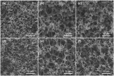
Subsequently, three monoliths were synthesized at different temperatures for phase separation while keeping the other experimental conditions the same (monoliths 4, 6, and 7 in Table 1). When the cooling temperature was set to 4 °C, it can be clearly observed that phase separation occurred in 20 s during the fabrication process of monolith 6. For monolith 4, phase separation gradually occurred within 2 min. When the cooling temperature was kept at 50 °C, the monolith could not form because of the evaporation of poor solvent and the extremely slow speed of phase separation. These phenomena demonstrate that the speed of the phase separation process was quite fast at lower temperature. In addition, SEM images (Fig. S1b and c, ESI†) provided illustrative insight into the impact of the cooling temperature on the morphologies of the two monoliths (monoliths 4 and 6). The pore size of monolith 6 was smaller and its skeleton was thinner compared with those of monolith 4, while the permeability of monolith 6 was 0.82 × 10⁻⁴ m2 and lower than that of monolith 4. Meanwhile, there was no obvious pore structure in monolith 7 (Fig. S1d, ESI†). These results illustrate that the lower cooling temperature can endow the monolith with a thinner skeletal structure and smaller pore size because of the high speed of phase separation and that the pore size of the monoliths can be scaled by adjusting the cooling temperature. Monomer concentration also plays an important role in the formation of monoliths. Therefore, the effect of different concentrations was investigated, and the results are listed in Table 1. When the concentration decreased from 182.9 to 166.7 mg mL−1, the permeability increased from 1.03 to 2.33 × 10⁻¹⁴ m2. Corresponding with these permeability results, both the pore size and skeleton density of the monolith decreased with decreasing monomer concentration (Fig. 2d and Fig. S1b, ESI†), while there was no homogenous pore structure in monolith 9 (Fig. S1e, ESI†) because of the lower concentration (149.2 mg mL−1).
According to the ratio of ODA to PMDA, it can be observed that excess amine groups were exposed on the ends of PAA chain. These amine groups can react with epoxy groups in octakis(glycidyldimethylsiloxy)octasilsesquioxane (crosslinker, POSS-epoxy) to introduce some epoxy groups, enabling the resulting PI-co-POSS monolith to be easily modified. As given in Table 1, the ratios of epoxy to terminal amine groups were set to 1/1 (monolith 11) and 1/2 (monolith 14) to investigate the influence of the amount of POSS-epoxy. Upon increasing the POSS-epoxy content in total monomers from 0 to 7.1%, the permeabilities of monoliths 11 and 14, respectively, increased to 4.01 × 10⁻¹⁴ and 3.85 × 10⁻¹⁴ m2. This result can be attributed to the loose structure of the PI-co-POSS monolith, resulting from the existence of the tough silsesquioxane cores and large network.28 Based on the above results (suitable permeability and porous morphology), monoliths 8, 11, and 14 were chosen for additional characterization and application in the following experiments.
Characterization of the PI and PI-co-POSS monoliths
In this study, PAA-based monoliths were first fabricated, then the thermal method were used to perform imidization to form a PI-based monoliths. ATR-IR spectra were used to confirm the transformation from PAA (the predecessor of monolith 8) to PI (monolith 8). As shown in Fig. 1, the characteristic peaks of the carboxyl group appeared at 3400–2200 cm−1 (Fig. 1a), while these signals disappeared in the spectrum of the PI monolith (Fig. 1b). More importantly, the characteristic absorption peaks at 1776, 1720, and 752 cm−1 were assigned as symmetrical and asymmetrical stretching vibrations and the bending vibration of the imide ring, respectively (Fig. 1b), confirming the existence of an aromatic imide structure. The signals of Si–O–Si stretching at 1089 and 799 cm−1 and the peak of the epoxy group at 909 cm−1 observed in Fig. 1c indicate that the POSS reagent was successfully introduced into the reaction system, and the epoxy groups were stable after imidization. These results demonstrate that POSS-epoxy successfully reacted with the amine group exposed at the ends of PAA chains and was introduced into the system.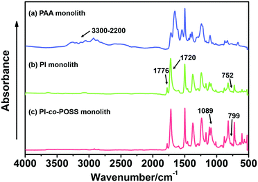 | ||
| Fig. 1 ATR-IR spectra of (a) PAA (the predecessor of monolith 8), (b) PI (monolith 8), and (c) PI-co-POSS (monolith 14) monoliths. | ||
To confirm the transformation of the porous morphology between the PAA and PI monoliths, SEM was employed. Fig. 2a and d show images of an interconnected network structure with pore sizes of ∼2 μm. The morphology of the PI monolith was almost maintained after the thermal imidization. Moreover, to verify the influence of the amount of POSS-epoxy in the microstructure, the PI and PI-co-POSS monoliths were also characterized by SEM. Likewise, there was no obvious difference between the porous structures of the PAA-co-POSS and PI-co-POSS monoliths, indicating that the porous structure was not influenced by imidization. In addition, as can be seen in Fig. 2d–f, both PI (monolith 8) and PI-co-POSS (monoliths 11 and 14) have homogeneous network structures and through-pores. A comparison of the SEM images of the PI (Fig. 2d) and PI-co-POSS (Fig. 2e and f) monoliths distinctly shows that the skeleton of the monolith became thinner when the POSS-epoxy was added to the polymerization. The porous structure was obviously favorable for fluid flow and mass exchange on the monolith. In addition, the pore size distributions and specific surface areas of the PI and PI-co-POSS monoliths were investigated by measuring nitrogen gas (N2) adsorption–desorption at 77 K, as shown in Fig. 3. It can be observed from the pore size distribution in Fig. 3b that micro- and mesopores also existed in the three monoliths. Combined with the SEM images, these results indicate that the PI and PI-co-POSS monoliths exhibit a hierarchically porous structure including micropores, mesopores, and macropores. Meanwhile, the surface areas of the three monoliths are, respectively, 7.05, 17.04, and 17.52 m2 g−1. These variations are attributed to the varying amounts of micro- and mesopores.
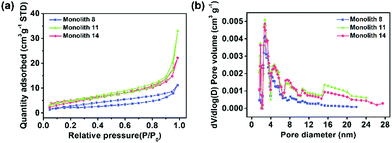 | ||
| Fig. 3 (a) Nitrogen adsorption–desorption isotherms of monolith 8, monolith 11, and monolith 14 and (b) the corresponding pore size distribution plots of monolith 8, monolith 11, and monolith 14. | ||
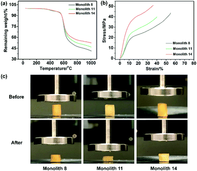
To evaluate the thermal stability of the PI and PI-co-POSS monoliths, TGA was adopted to test these samples under a nitrogen atmosphere. One can observe in Fig. 4a that the pure PI monolith lost its weight from 555 °C, while the weight loss of the two PI-co-POSS monoliths apparently occurred from 539 and 534 °C, respectively. A comparison of the TGA curves of the PI and PI-co-POSS monoliths reveals a slight decrease in decomposition temperature occurring for the PI-co-POSS monoliths, because the organic section of POSS-epoxy exhibited a lower degradation temperature. The TGA diagrams demonstrate that the PI and PI-co-POSS monoliths have great thermal stability and that ring-opening polymerization successfully occurred between the epoxy group in POSS-epoxy and the amino group in pure PAA because of the difference of residual weight. In the completely dried state, the PI and PI-co-POSS monoliths were characterized by compression testing to investigate and compare their mechanical strengths (Fig. 4b). Compression tests were implemented by compressing cylindrically shaped PI and PI-co-POSS monoliths from 0 to 500 N, as shown in Fig. 4c. Note that these samples did not break during the tests. These results indicate that these monoliths exhibited great mechanical strength. Meanwhile, the values of the compressive moduli were obtained by calculation with strains ranging from 0 to 10%. The results are given in Table 2. It can be observed that the compressive moduli of the monoliths increased from 2.24 to 3.46 MPa upon increasing the POSS amount from 0 to 7.1%. Because POSS reagents with distinctive cage-like structures have good mechanical stability, the mechanical strength of materials can be significantly improved when they are incorporated within the polymer. Water contact angle test was employed to determine the hydrophobicity or hydrophilicity of the PI and PI-co-POSS monoliths. As observed in Fig. 5, the values of the water contact angles of monoliths 8, 11, and 14 successively increased from 121 to 139 °C with the increasing amount of POSS. Moreover, the comparison of the water contact angles between Fig. 5a–c indicated that the introduction of POSS-epoxy can enhance the hydrophobic properties of the monoliths because of the existence of the Si–O–Si structural units and the –CH2– hydrophobic groups in POSS-epoxy. These values demonstrate that the skeletons of the PI and PI-co-POSS monoliths are hydrophobic materials.
| Monolith 8 | Monolith 11 | Monolith 14 | |
|---|---|---|---|
| BET surface area (m2 g−1) | 7.05 | 17.04 | 17.52 |
| Compressive modulus (MPa) | 2.24 | 2.59 | 3.46 |
 | ||
| Fig. 5 Water contact angles of the surfaces of (a) monolith 8, (b) monolith 11, and (c) monolith 14. | ||
Application of the PI and PI-co-POSS monoliths in oil adsorption
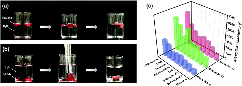
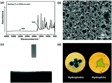
According to the results of the water contact angle test, the PI and PI-co-POSS monoliths exhibit hydrophobicity. Furthermore, the densities of the PI and PI-co-POSS monoliths were calculated, and the densities of monoliths 8, 11 and 14 were 0.43, 0.42 and 0.41 g cm−3, respectively. These values were further lower than the densities of traditional polyimide materials (1.38–1.43 g cm−3), indicating that the resulting PI and PI-co-POSS monoliths were rich in macropores and showed higher porosity to facilitate adsorption. Therefore, adsorption tests were employed to investigate the ability of the monoliths to adsorb oil. As shown in Fig. 6a, toluene was dyed with oil red and combined with deionized water. Monolith 14 as an example was placed in a bottle containing this mixture of toluene and water. It can be seen that the toluene was instantly and completely adsorbed by the monolith. Similarly, CHCl3 dyed with oil red was added to deionized water, and then CHCl3 was instantly and completely adsorbed when it contacted with monolith 8, as shown in Fig. 6b. These phenomena demonstrate that the water and oil can be separated by means of the monoliths absorbing oil from the oil–water mixture. Moreover, the oil adsorption capacities of the PI and PI-co-POSS monoliths were evaluated for various organic solvents and silicone oil. As shown in Fig. 6c, the adsorption capacities for all organic solvents and silicone oil of the PI-co-POSS monoliths were obviously higher than those of the PI monolith. For example, for silicone oil, the adsorption capacities of monoliths 8, 11, and 14 were 1271.4, 2532.7, and 2398.4 mg g−1, respectively. The values for the PI-co-POSS monoliths were higher than those for similar PI materials.29 Because the PI-co-POSS monoliths exhibited stronger hydrophobicity than the PI monolith, as demonstrated by the water contact angle test, this made organic solvents have better wettability on the surfaces of the monoliths. Meanwhile, the greater permeabilities and pore sizes of the PI-co-POSS monoliths endowed them with high oil adsorption capacities, and their through-pore structures not only provided storage space for organic solvents and oil but also facilitated the mass transfer of substances on the monoliths. We also found that the resulting monoliths swelled during adsorption; the volumes of monoliths 8, 11 and 14 in different solvents are shown in Table S1 (ESI†). Furthermore, taking chloroform as an example, the adsorption capacities of the PI and PI-co-POSS monoliths could achieve maximum adsorption capacities within 3 min, and did not decrease after 10 cycles (as shown in Fig. S2, ESI†). It was strongly proved that the resulting materials possessed excellent stability and reusability.In addition, one layer of the PI-co-POSS monolith could be modified with branched polyethylenimine (bPEI) which exhibited hydrophilicity. Because of the introduction of POSS-epoxy, some epoxy may be exposed on the skeleton surface of the PI-co-POSS monolith, indicating that bPEI can modify the PI-co-POSS surface. At first, the POSS-epoxy was heated to 300 °C for 20 min, then its ATR-IR spectrum was measured to confirm the stability of the epoxy group after thermal imidization. As can be observed in Fig. S3 (ESI†), the characteristic peak of the epoxy group in the heated POSS-epoxy appeared at 909 cm−1, demonstrating that most epoxy groups did not decompose but could be modified. In this case, we chose monolith 14 to modify because a greater amount of POSS-epoxy was introduced into the reaction system. The process of modification of the PI-co-POSS monoliths with bPEI is shown in Scheme 2b. As observed from the spectrum of the modified PI-co-POSS monolith, the peaks at 3068 and 1649 cm−1 can be assigned as the characteristic signals of the N–H vibration, demonstrating that the PI-co-POSS monolith was successfully modified (Fig. 7a). And the modified layer in the PI-co-POSS monolith was characterized by SEM, as shown in Fig. 7b. It can be observed that the homogeneous network structure and through-pores were not damaged after modification. Moreover, the modified PI-co-POSS monolith was characterized by TGA, and the result is shown in Fig. S4 (ESI†). There was a slight weight loss before 100 °C, because the modified PI-co-POSS monolith is hydrophilic and can easily adsorb water even after being dried. When the temperature increased to 200 °C, the modified PI-co-POSS monolith exhibited a notable weight loss because of the low thermal stability of bPEI. The result proved that the bPEI was successfully grafted onto the PI-co-POSS monolith, and decreased the thermal stability of the resulting monoliths. Then, a water contact angle test was employed to investigate the hydrophilicity of the modified layer. As shown in Fig. 7c, water drops could instantly be absorbed on the surface of the modified PI-co-POSS monolith with bPEI, for which the contact angle could not even be calculated. This phenomenon further demonstrates that the PI-co-POSS monolith was successfully modified and exhibited hydrophilicity. Meanwhile, water drops dyed with methyl blue that were dropped on the unmodified layer (hydrophobic layer) could not be absorbed. However, when the water drops were dropped on the modified layer (hydrophilic layer), they were instantly absorbed (Fig. 7d). These results illustrate that PI-co-POSS monoliths have great potential in liquid diode application to achieve oil–water separation because they could simultaneously have hydrophilic and hydrophobic layers after modification.
Conclusions
In this study, a novel, cost-effective, and green synthesis process was developed for the preparation of PI and hybrid PI (PI-co-POSS) monoliths with great thermal stability and good mechanical strength, thereby overcoming the existing shortcomings of preparation of PI-based aerogels involving complicated preparation processes and high cost. In the preparation process, PAA and PAA-co-POSS monoliths were first synthesized by TIPS using DMF as good solvent and water as poor solvent. Then PI and PI-co-POSS monoliths can be directly obtained by thermal imidization. SEM images and N2 adsorption–desorption curves of the resulting monoliths demonstrated that they not only had a homogenous pore morphology but also a hierarchical pore structure and through-pores, favouring mass transfer and fluid flow. And the good hydrophobic properties of the resulting monoliths were confirmed by water contact angle test. Moreover, through adsorption tests, the resulting monoliths for seven organic solvents and silicone oil were found to exhibit good adsorption performance and can be used in oil–water separation. It would be expected that other PI-based monoliths with great chemical and physical properties can be synthesized via this universal approach that can be applied in other fields in the future.Experimental
Materials
PMDA (≥98%) and ODA (≥98%) were obtained from Tokyo Chemical Industry Co., Ltd (Japan). POSS-epoxy was purchased from Sigma (USA). The deionized water used in all the experiments was purified with a Milli-Q system (Millipore, Inc., USA). Super dehydrated DMF (99.5%) and bPEI (with an average molecular weight of ∼600) were purchased from FUJIFILM Wako Pure Chemical Corp. (Japan). Toluene, TEA, and DMF were purchased from Nacalai Tesque, Inc. (Japan). All reagents were used as received.Preparation of a PI monolith
Generally, the preparation of PAA is the first step of the synthesis method of PI. To synthesize PAA, ODA (10.4 mol, 2.07 g) was first dissolved in super dehydrated DMF (15.0 mL), then 10.0 mmol PMDA (2.00 g) was added into the above solution under a nitrogen atmosphere which was followed by magnetic stirring at room temperature for 24 h. The prepared PAA solution was transferred into a glass bottle and stirred at 85 °C until its temperature reached equilibrium. Deionized water and TEA were then added dropwise into the PAA solution, and the mixture was heated at 85 °C until it became a yellow and transparent solution. The mixture was then transformed into a 25 °C water bath for 12 h and became an opaque yellow hydrogel. Subsequently, 50% DMF in H2O, 25% DMF in H2O, and 100% H2O in sequence were selected as exchange solvents. The product was then dried by vacuum drying for 4 h at ambient temperature to obtain a PAA monolith. Finally, the PAA monolith was converted to a PI monolith. The detailed procedure was as follows: the PAA monolith was placed in an oven with temperature programming (80 °C for 2 h, 120 °C for 1 h, 150 °C for 1 h, 180 °C for 2 h, 250 °C for 1 h, and 280 °C for 2 h in proper order). After the temperature of the oven was reduced below 50 °C, a PI monolith can be obtained.Preparation of PI-co-POSS monoliths
10.4 mmol ODA (2.07 g) was completely dissolved in DMF (13 mL) under a nitrogen atmosphere in an ice bath, then 10.0 mmol PMDA (2.00 g) was added to the solution under stirring at room temperature for 1 h. Subsequently, a solution of 0.19 or 0.39 g POSS-epoxy dissolved in 2 mL super dehydrated DMF was added dropwise to react for 24 h. The resulting solution is the precursor material for monolithic PI-co-POSS materials. The other preparation processes for PI-co-POSS monoliths are the same as those for the PI monolith.Surface modification of the PI-co-POSS monoliths
A certain mass of bPEI was dissolved in ethanol to prepare a bPEI–ethanol solution (30%, v/v). Then, a portion of the PI-co-POSS monolith was immersed in the solution to react for 24 h at 50 °C. Finally, the modified PI-co-POSS monolith was dried by vacuum drying after unreacted bPEI was washed away with ethanol.Determination of absorption capacity
Different organic solvents (tetrahydrofuran, hexane, DMF, acetic acid, chloroform, toluene, and 2-propanol) and silicone oil were adopted to measure the absorption capacities of the resulting monoliths. Each weighed monolith was immersed in a certain solvent and placed in a shaker. After 10 min, the monolith was removed from the solvent, wiped dry, and weighed again to obtain its mass. The mass difference before and after adsorption divided by the mass before adsorption was used to calculate the adsorption capacity of the monolith.Instruments and methods
The microstructures and pore morphologies of the monolithic materials were observed by scanning electron microscopy (SEM) (Hitachi SU-3500, Japan). The attenuated total reflection infrared (ATR-IR) spectra were determined on a spectrometer (Thermo Scientific Nicolet iS5, Japan) equipped with an iD5 ATR attachment. Thermogravimetric analysis (TGA) curves were recorded using a thermogravimetric analyzer (Hitachi STA7200RV, Japan) by heating from 40 to 1000 °C under nitrogen protection. The water contact angle was obtained on a Drop Master DM300 (Kyowa Interface Science, Japan) with 1.0 μL water drops. The compression performance of the materials was measured by using a universal testing machine (Shimadzu EZ Graph, Japan) with a compression speed of 1 mm min−1. The maximum compression strain (ε) was set to 70%. The Brunauer–Emmett–Teller (BET) surface area was evaluated by using a nitrogen adsorption–desorption analyzer (Quantachrome Instruments, USA). The pore diameter distribution and pore volume were acquired using density functional theory (DFT).From Darcy's law, the permeabilities of the resulting monoliths can be calculated according to the equation B0 = FηL/(πr2ΔP), in which F (m3 s−1) is the flow rate of the mobile phase, η (Pa s) is the viscosity of the mobile phase (0.89 × 10⁻³ Pa s for water), L (m) and r (m) are the effective length and inner diameter of the column, respectively, and ΔP (Pa) is the pressure drop across the monolith.30 The ΔP data were measured with a digital pressure gauge (Krone KDM30, Japan). The flow rates were controlled by using a digital quantitative tubing pump (As One DSP-100SA, Japan).
Conflicts of interest
There are no conflicts to declare.Acknowledgements
This work was supported by JSPS KAKENHI Grants (No. 19H02778, No. 20H02797). Y. W. and L. Z. would like to thank the China Scholarship Council (CSC) for scholarship support.Notes and references
- C. E. Sroog, Polyimides, Prog. Polym. Sci., 1991, 16, 561–694 CrossRef CAS.
- T. Kurosawa, T. Higashihara and M. Ueda, Polyimide memory: a pithy guideline for future applications, Polym. Chem., 2013, 4, 16–30 RSC.
- L. Lin, P. Ye, C. Cao, Q. Jin, G. S. Xu, Y. H. Shen and Y. P. Yuan, Rapid microwave-assisted green production of a crystalline polyimide for enhanced visible-light-induced photocatalytic hydrogen production, J. Mater. Chem. A, 2015, 3, 10205–10208 RSC.
- Y. Wang, S. Xu, T. Chen, H. Guo, Q. Liu, B. Ye, Z. Zhang, Z. He and S. Cao, Synthesis and preliminary photovoltaic behavior study of a soluble polyimide containing ruthenium complexes, Polym. Chem., 2010, 1, 1048–1055 RSC.
- Q. Feng, M. Li, T. Wang, Y. Chen, X. Wang, X. Zhang, X. Li, Z. Yang, L. Feng, J. Zheng, H. Xu, T. Zhai and Y. Jiang, Low-temperature growth of three dimensional ReS2/ReO2 metal–semiconductor heterojunctions on graphene/polyimide film for enhanced hydrogen evolution reaction, Appl. Catal., B, 2020, 271, 118924 CrossRef CAS.
- J. Liu, J. Tan, Y. Zeng, Y. Liu, K. Zeng, Y. Liu, R. Wu and H. Chen, Synthesis and characterization of high-barrier polyimide containing rigid planar moieties and amide groups, Polym. Test., 2017, 61, 83–92 CrossRef CAS.
- B. S. Ghanem, R. Swaidan, E. Litwiller and I. Pinnau, Ultra-microporous triptycene-based polyimide membranes for high-performance gas separation, Adv. Mater., 2014, 26, 3688–3692 CrossRef CAS PubMed.
- N. C. Pradhan, C. S. Sarkar, S. Niyogi and B. Adhikari, Separation of phenol-water mixture by membrane pervaporation using polyimide membranes, J. Appl. Polym. Sci., 2002, 83, 822–829 CrossRef CAS.
- T. Nema, E. C. Chan and P. C. Ho, Applications of monolithic materials for sample preparation, J. Pharm. Biomed. Anal., 2014, 87, 130–141 CrossRef CAS PubMed.
- C. M. Parlett, K. Wilson and A. F. Lee, Hierarchical porous materials: catalytic applications, Chem. Soc. Rev., 2013, 42, 3876–3893 RSC.
- F. Svec and Y. Lv, Advances and recent trends in the field of monolithic columns for chromatography, Anal. Chem., 2015, 87, 250–273 CrossRef CAS PubMed.
- Y. Zhang, Y. Liu, X. Wang, Z. Sun, J. Ma, T. Wu, F. Xing and J. Gao, Porous graphene oxide/carboxymethyl cellulose monoliths, with high metal ion adsorption, Carbohydr. Polym., 2014, 101, 392–400 CrossRef CAS PubMed.
- S. Mizuno, T.-A. Asoh, Y. Takashima, A. Harada and H. Uyama, Cyclodextrin cross-linked polymer monolith for efficient removal of environmental pollutants by flow-through method, Polym. Degrad. Stab., 2019, 160, 136–141 CrossRef CAS.
- S. Ungureanu, H. Deleuze, C. Sanchez, M. I. Popa and R. Backov, First Pd@organo-Si(HIPE) open-cell hybrid monoliths generation offering cycling Heck catalysis reactions, Chem. Mater., 2008, 20, 6494–6500 CrossRef CAS.
- H. Liu, J. Diao, Q. Wang, S. Gu, T. Chen, C. Miao, W. Yang and D. Su, A nanodiamond/CNT-SiC monolith as a novel metal free catalyst for ethylbenzene direct dehydrogenation to styrene, Chem. Commun., 2014, 50, 7810–7812 RSC.
- Y. Shu, J. Maruyama, S. Iwasaki, Y. Shen and H. Uyama, Activated Carbon Monolith Derived from Amygdalus Pedunculata Shell and Polyacrylonitrile for Supercapacitors, Bull. Chem. Soc. Jpn., 2017, 90, 1333–1336 CrossRef CAS.
- H. Bi, T. Lin, F. Xu, Y. Tang, Z. Liu and F. Huang, New graphene form of nanoporous monolith for excellent energy storage, Nano Lett., 2016, 16, 349–354 CrossRef CAS PubMed.
- Y. Wang, S. Ma, L. Zhang, N. Zhang, Y. Li, J. Ou, Y. Shen and M. Ye, Fast fabrication of a hybrid monolithic column containing cyclic and aliphatic hydrophobic ligands via photo-initiated thiol-ene polymerization, J. Sep. Sci., 2019, 42, 1332–1340 CrossRef CAS PubMed.
- H. Lin, J. Ou, Z. Liu, H. Wang, J. Dong and H. Zou, Thiol-epoxy click polymerization for preparation of polymeric monoliths with well-defined 3D framework for capillary liquid chromatography, Anal. Chem., 2015, 87, 3476–3483 CrossRef CAS PubMed.
- G. Yang, T. Ning, W. Zhao, W. Deng and X. Liu, Robust ambient pressure dried polyimide aerogels and their graphene oxide directed growth of 1D–2D nanohybrid aerogels using water as the only solvent, RSC Adv., 2017, 7, 16210–16216 RSC.
- J. Lee and J. Y. Chang, Preparation of a compressible and hierarchically porous polyimide sponge via the sol–gel process of an aliphatic tetracarboxylic dianhydride and an aromatic triamine, Chem. Commun., 2016, 52, 10419–10422 RSC.
- H. Wang, T. Wang, S. Yang and L. Fan, Preparation of thermal stable porous polyimide membranes by phase inversion process for lithium-ion battery, Polymer, 2013, 54, 6339–6348 CrossRef CAS.
- Y. Xin, Q. Xiong, Q. Bai, M. Miyamoto, C. Li, Y. Shen and H. Uyama, A hierarchically porous cellulose monolith: a template-free fabricated, morphology-tunable, and easily functionalizable platform, Carbohydr. Polym., 2017, 157, 429–437 CrossRef CAS PubMed.
- H. Zhu, Z. Liu, Y. Wang, D. Kong, X. Yua and Z. Xie, Nanosized CaCO3 as hard template for creation of intracrystal pores within silicalite-1 crystal, Chem. Mater., 2008, 20, 1134–1139 CrossRef CAS.
- T. Shimizu, K. Matsuura, H. Furue and K. Matsuzak, Thermal conductivity of high porosity alumina refractory bricks made by a slurry gelation and foaming method, J. Eur. Ceram. Soc., 2013, 33, 3429–3435 CrossRef CAS.
- X. Y. Yang, L. H. Chen, Y. Li, J. C. Rooke, C. Sanchez and B. L. Su, Hierarchically porous materials: synthesis strategies and structure design, Chem. Soc. Rev., 2017, 46, 481–558 RSC.
- J. Kiefer, J. L. Hedrick and J. G. Hilborn, Macroporous thermosets by chemically induced phase separation, Adv. Polym. Sci., 1999, 147, 161–247 CrossRef CAS.
- Y. Lee, J. Huang, S. Kuo, J. Lu and F. Chang, Polyimide and polyhedral oligomeric silsesquioxane nanocomposites for low-dielectric applications, Polymer, 2005, 46, 173–181 CrossRef CAS.
- J. Kim, J. Kwon, S. Kim, M. Kim, D. Lee, S. Lee, G. Kim, J. Lee and H. Han, One-step synthesis of nano-porous monolithic polyimide aerogel, Microporous Mesoporous Mater., 2016, 234, 35–42 CrossRef CAS.
- Y. Wang, S. Ma, Y. Chen, L. Zhang, J. Ou, Y. Shen and M. Ye, Thiol-radical-mediated polymerization for preparation of POSS-containing polyacrylate monoliths in capillary liquid chromatography, Talanta, 2018, 190, 62–69 CrossRef CAS PubMed.
Footnote |
| † Electronic supplementary information (ESI) available. See DOI: 10.1039/d1ma00185j |
| This journal is © The Royal Society of Chemistry 2021 |

