
 Open Access Article
 This Open Access Article is licensed under a
 Creative Commons Attribution 3.0 Unported Licence
Sol–gel based structural designs of macropores and material shapes of metal–organic framework gels†
Yosuke
Hara
 *a,
Kohei
Manabe
a,
Kazuki
Nakanishi
bc and
Kazuyoshi
Kanamori
*a
*a,
Kohei
Manabe
a,
Kazuki
Nakanishi
bc and
Kazuyoshi
Kanamori
*a
aDepartment of Chemistry, Graduate School of Science Kyoto University Kitashirakawa, Sakyo-ku, Kyoto 606-8502, Japan. E-mail: hara.yosuke@icm.kyoto-u.ac.jp; kanamori@kuchem.kyoto-u.ac.jp
bInstitute of Materials and Systems for Sustainability Nagoya University Furo-cho, Chikusa-ku, Nagoya, Aichi 464-8601, Japan
cInstitute for Integrated Cell-Material Sciences, Kyoto University Yoshida, Sakyo-ku, Kyoto 606-8501, Japan
First published on 17th May 2021
Abstract
We have developed a general synthetic strategy to control macroporous structures and material shapes of metal–organic framework (MOF) gels via a sol–gel based structural control process. A series of 1,3,5-benzene tricarboxylic acid (BTC) based MOF gels, Cr-BTC and Zr-BTC, have been chosen as a proof of concept.
Sol–gel processing of metal–organic frameworks (MOFs) has been attracting considerable interest in recent years because of their potential use in a wide variety of applications, including gas storage, separation, adsorption, catalysis, and life science.1 By applying the idea of the sol–gel process, which has been well-developed in the field of inorganic materials, to the self–assembly process of MOFs, the enhancement of the property of MOFs for their applications is expected.1 In particular, structuring of MOFs at (meso-)/macroscopic scales by the sol–gel process is one of the most important topics to overcome the poor handling properties and mechanical instability of aggregates of microcrystalline MOF particles.1b,2 When applying the sol–gel process to MOF synthesis, the sol–gel transition of precursor solutions to MOF gels, that is, the formation of three-dimensional MOF-based spanning networks, can be considered as a key element in the synthesis. For nearly a decade, the sol–gel transition of metal ions and organic linker solution into MOF gels has been reported in many kinds of MOFs.3 However, most of the studies focused on the control of nucleation, growth and aggregation tendency of MOFs.3 Therefore, the advantage of the sol–gel process, which realizes high level structural control for introducing (meso-)/macroscopic targeted structures,4 has not yet been applied to MOF gels.
In 2019, we reported meso-/macroporous UiO-66-NH2, using the formula [Zr6O4(OH)4(BDC-NH2)6] (BDC-NH2 = 2-aminoterephthalic acid), monoliths via a self–assembly-induced phase separation (SIPS) technique and subsequent solvothermal treatment.5 Although commonly obtained MOF gels have low crystallinity,3 we developed a strategy for higher degree of crystallization while maintaining macroscopic morphology of MOF gels by optimizing post-treatment conditions by taking the UiO-66-NH2 system as a proof of concept.5 Therefore, establishing a synthetic route to control the macroscopic morphology of MOF gels plays a pivotal role in realizing multiscale structural control of the MOFs with targeted pore sizes, which facilitates the use of MOFs in applications in which efficient mass transfer of the guest molecule is important. However, since the first report on the UiO-66-NH2 system, no reports applying the SIPS technique to other kinds of MOF gels have been reported.
Here, we report a synthetic route to control macroporous structures of 1,3,5-benzene tricarboxylic acid (BTC) based MOF gels, Cr(III)-BTC gels (denoted as Cr-BTC gels) and Zr(IV)-BTC gels (denoted as Zr-BTC gels), by the SIPS technique using a hydrophobic polymer as a phase separation inducer. In addition, we demonstrate the top-down processability of the obtained macroporous MOF gels toward macroporous microparticles by selecting Cr-BTC as a representative.
Firstly, we discuss the formation and control of macroporous structures of Cr-BTC gels. The sol–gel transition behaviour of a solution of Cr(III) salt and BTC has been reported elsewhere.3c,6 The typical chemical formula of Cr-BTC is Cr3XO(BTC)2·nH2O (X = typically F, n ≈ 28), known as MIL-100(Cr), a crystalline MOF powder.7Fig. 1 shows a schematic of the synthesis of the macroporous Cr-BTC metal–organic gels. The suitable starting compositions and reaction conditions have been specified, in which the transient macroscopic structure of the phase separation can be arrested by the sol–gel transition. Typically, Cr(NO3)3·9H2O (12 mmol) and BTC (8 mmol) were used as an inorganic precursor and organic linker, respectively. We used a mixture of ethanol (EtOH) and tetrahydrofuran (THF) (13 mL, VEtOH![[thin space (1/6-em)]](https://www.rsc.org/images/entities/char_2009.gif) :VTHF = 1:1) as a solvent to ensure good solubility of BTC, and to maintain low internal pressure in a glass tube at gelation temperature, 60 °C. When we used non-alcoholic solvent such as N,N-dimethylformamide (DMF), gelation of Cr-BTC did not occur within 1 d. Polytetrahydrofuran (PTHF, Mn = 2900) was used as a phase separation inducer, with the idea that intrinsically hydrophilic Cr-BTC has low compatibility with hydrophobic polymers. This idea follows our previous report on a Zr-BDC-NH2 based sol–gel system, in which a hydrophobic polymer, poly(propylene glycol) (PPG), acted as a phase separation inducer in the course of polymerization.5 The mixture of Cr(NO3)·9H2O, BTC, solvent, and the phase separation inducer was sealed in a glass tube, and transferred into a water bath at 60 °C. The macroporous opaque green gel was obtained (Fig. 1) possibly as a result of the mismatched growth3a of Cr-BTC clusters. After washing with ethanol and n-hexane, the wet gels were dried at 40 °C, and then 150 °C in vacuo.
:VTHF = 1:1) as a solvent to ensure good solubility of BTC, and to maintain low internal pressure in a glass tube at gelation temperature, 60 °C. When we used non-alcoholic solvent such as N,N-dimethylformamide (DMF), gelation of Cr-BTC did not occur within 1 d. Polytetrahydrofuran (PTHF, Mn = 2900) was used as a phase separation inducer, with the idea that intrinsically hydrophilic Cr-BTC has low compatibility with hydrophobic polymers. This idea follows our previous report on a Zr-BDC-NH2 based sol–gel system, in which a hydrophobic polymer, poly(propylene glycol) (PPG), acted as a phase separation inducer in the course of polymerization.5 The mixture of Cr(NO3)·9H2O, BTC, solvent, and the phase separation inducer was sealed in a glass tube, and transferred into a water bath at 60 °C. The macroporous opaque green gel was obtained (Fig. 1) possibly as a result of the mismatched growth3a of Cr-BTC clusters. After washing with ethanol and n-hexane, the wet gels were dried at 40 °C, and then 150 °C in vacuo.
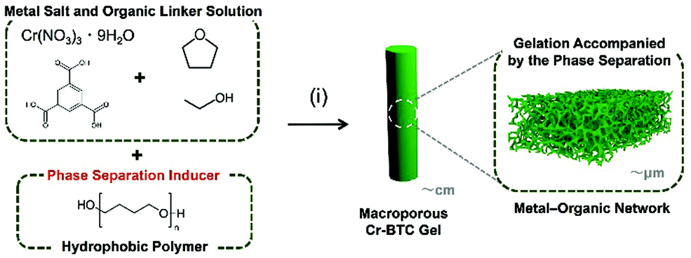 | ||
| Fig. 1 Schematic of the synthesis of the macroporous Cr-BTC metal–organic framework gels, which consist of amorphous metal–organic networks. (i) Gelation accompanied by the phase separation from a homogeneous solution of metal salt, organic linker, solvent, and phase separation inducer. The macroporous robust Cr-BTC gel was prepared. Polytetrahydrofuran (PTHF, Mn = 2900), which is a hydrophobic polymer, was used as a phase separation inducer in a mixture of ethanol and tetrahydrofuran (Vethanol, Vtetrahydrofuran = 1:1). | ||
The formation and coarsening of the interconnected macroporous structures were controlled by adopting a PTHF amount as a variable. To apply the SIPS technique to the sol–gel process, it is important to optimize the starting composition and synthetic parameters, in which transparent non-macroporous gels can be formed without a phase separation inducer.5 Without PTHF, a transparent dark green gel was obtained, and the dried gel had a non-macroporous structure (Fig. S1A, ESI†), and with appropriate amounts of PTHF, macroporous structures were formed. Fig. 2A and Fig. S2 (ESI†) show scanning electron microscope (SEM) images of the Cr-BTC gels with different amounts of PTHF, and formation and coarsening of the interconnected macroporous structure were observed with an increase of the PTHF amount. At wPTHF = 1.3 g, in addition to the continuous macropores, isolated macropores8 were observed within the skeletons in addition to the continuous macropores as a result of secondary phase separation (Fig. S2B, ESI†). The mercury intrusion results show that the macropore diameter was controlled from 1.3 μm to 3.0 μm in the range of starting composition (Fig. 2B, C and Table S1, ESI†). When the macroporous Cr-BTC gel was prepared in the glass tube, the obtained macroporous Cr-BTC gel had a rod-like crack-free monolithic form (Fig. 2D). It is worth noting that this crack-free monolithic form can be preserved whenever the continuous macroporous morphology was formed (Fig. S1, ESI† and Fig. 2D). The introduction of continuous well-defined macroporous structures can reduce the local shrinkage stresses to allow isotropic shrinkage during the drying process, and the crack-free monolithic form of Cr-BTC gels was preserved.
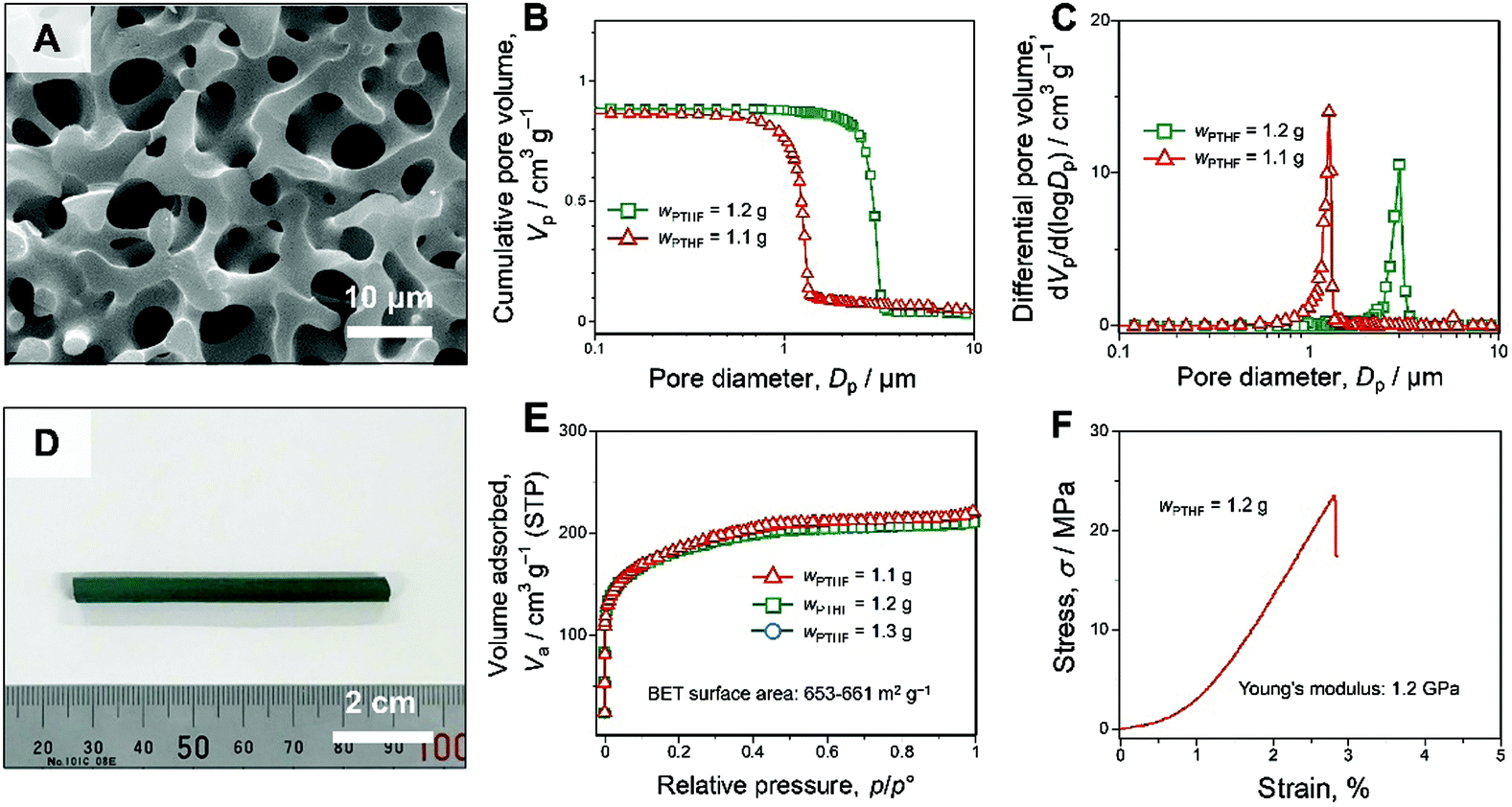 | ||
| Fig. 2 Microstructure and properties of the as-dried macroporous Cr-BTC gels (the detailed synthesis conditions are shown in the ESI†). (A) A SEM image of the as-dried macroporous Cr-BTC gels prepared with PTHF: wPTHF = 1.2 g. (B) Cumulative and (C) differential pore size distributions of the as-dried macroporous Cr-BTC gels with a varied amount of PTHF. (D) Appearance of the as-dried macroporous Cr-BTC gel prepared with PTHF: wPTHF = 1.2 g. (E) Nitrogen adsorption–desorption isotherms of the as-dried Cr-BTC gels with varied amounts of PTHF. (F) Stress–strain curve of the uniaxial compression test on the as-dried macroporous gel: wPTHF = 1.2 g. | ||
The energy dispersive X-ray spectroscopy (EDS) results of the (non-)macroporous Cr-BTC gels show uniform distributions of Cr and BTC, and impurities were not observed (Fig. S3–S6 and Tables S2, S3, ESI†). The Fourier transform infrared spectroscopy (FTIR) spectra show that the absorption bands of the two samples, Cr-BTC gels prepared with and without PTHF, were almost the same in the range 400 to 4000 cm−1 (Fig. S7, ESI†). These results suggest that both of the non-macroporous and macroporous Cr-BTC gels had similar chemical structures.
The X-ray diffraction (XRD) patterns of the samples show that the diffraction peaks of the Cr-BTC gels (wPTHF = 0 g, 1.1 g, 1.2 g, and 1.3 g) had only negligible differences (Fig. S1B and S8, ESI†). In addition, XRD patterns of the samples show only weak and broad peaks, which are similar to the previously reported Cr-BTC gels.3c Although the crystalline framework structure was undetectable, the nitrogen adsorption–desorption measurement of the Cr-BTC gels shows high specific surface area about 653–661 m2 g−1 calculated by the Brunauer–Emmett–Teller (BET) method, which suggests the presence of the microporous structure derived from the MOF network (Fig. 2E and Table S1, ESI†). To investigate the structural difference between the conventional MIL-100(Cr) particles (Fig. S19, ESI†) and the Cr-BTC gels, the micropore size distribution of the samples was estimated by the non-local density functional theory (NLDFT) (Fig. 3). The pores derived from the two types of pore cages (Fig. S10, ESI†) can be assigned to 1.2 nm and 1.5 nm in the NLDFT pore size distributions by analysing the conventional MIL-100(Cr) particles with assumption of N2-carbon at 77 K on a slit pore model (Fig. 3B). Comparing the results of NLDFT analysis between conventional MIL-100(Cr) particles and the as-dried Cr-BTC gels, both samples have micropores with two peaks at 1.2 nm and 1.5 nm (Fig. 3B). These results imply that the obtained Cr-BTC gels have a microporous structure derived from the local network of MOF crystallites. In addition, we consider that the space between the crystallites, which is derived from the low crystallinity, provided the pore distribution with the peak at 1.8 nm (Fig. 3B).
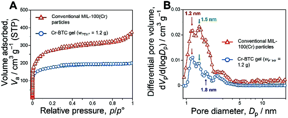 | ||
| Fig. 3 Micro-/mesoporous structures of the as-dried macroporous Cr-BTC gel and the conventional MIL-100(Cr) particles. (A) Nitrogen adsorption–desorption isotherms of the samples and (B) pore size distributions obtained by NLDFT analysis. The BET surface area of conventional MIL-100(Cr) particles is calculated to be 1050 m2 g−1. | ||
The Barrett–Joyner–Halenda (BJH) pore size distributions and isotherms of the Cr-BTC gels indicate the presence of mesopores below 10 nm (Fig. S11, ESI†). We consider that these mesopore size distributions are derived from the pores between the primary particles which constitute the skeletons (Fig. S12, ESI†).
In addition, to investigate the mechanical strength of macroporous Cr-BTC gels, a uniaxial compression test was performed (Fig. 2F). The macroporous Cr-BTC gel (wPTHF = 1.2 g) was shaped into a cylinder with a diameter of 5 mm and a height of 5 mm. Young's modulus of the macroporous Cr-BTC gel calculated from the linear elastic region was 1.2 GPa. This result confirms the high mechanical stability of Cr-BTC gels.
The compatibility in a binary polymeric system can be estimated by the thermodynamic treatment known as the Flory–Huggins equation.9 The Gibbs free energy change of mixing for a binary system, ΔG is expressed as [eqn (1)];
| ΔG ∝ RT[{(φ1/P1)lnφ1 + (φ2/P2)lnφ2} + {χ12φ1φ2}] | (1) |
Secondly, we discuss the formation and control of macroporous structures of Zr-BTC gels. The sol–gel transition behaviour of a solution of Zr(IV) salt and BTC has been reported.3d The typical chemical formula of Zr-BTC is Zr6O4(OH)4BTC2(HCOO)6, known as MOF-808, a crystalline MOF powder.10 As mentioned above, macroporous structures of two kinds of MOF gels, Zr-BDC-NH2 and Cr-BTC, have been successfully controlled by using hydrophobic polymer as the phase separation inducer. In the Zr-BTC based sol–gel system, we also applied a hydrophobic polymer as a phase separation inducer. The suitable starting compositions and reaction conditions have been specified. We summarized the starting compositions of synthesis of macroporous MOF gels via the SIPS technique in Fig. S15 (ESI†). In the Zr-BTC system, we used PPG as a hydrophobic polymer (Fig. S15, ESI†). Without PPG, transparent non-macroporous Zr-BTC gels have been obtained via the sol–gel process from the mixture of metal salt ZrOCl2·8H2O, organic linker BTC, and solvent N,N-dimethylformamide (DMF) and formic acid (HCOOH) (Fig. S16, ESI†). In the presence of hydrophobic polymer PPG (Mn = 1000), however, formation of the interconnected macroporous structures was observed (Fig. S17A–C, ESI†). The details of synthetic conditions and discussion of the synthesis of (non-)macroporous Zr-BTC can be found in the ESI.†
Furthermore, by taking advantage of the shape of the bulky monolithic gels, we demonstrate here the top-down processability toward macroporous microparticles. In applications in which mass transfer rate of the guest molecule has a significant impact, the material shapes are also important depending on the specific applications and set-up.11Fig. 4A shows a schematic of the synthesis of the macroporous Cr-BTC microparticles. Simply, the obtained as-dried gels were processed with top-down crushing and classifying processes into large sized microparticles (45–100 μm) by using stainless sieves. Fig. 4B–D show the SEM images of the processed macroporous Cr-BTC microparticles. The as-dried macroporous Cr-BTC microparticles had a well-defined macroporous structure, which did not collapse during the crushing process. This result shows the high formability of the macroporous monolithic MOF gels by top-down processing.
 | ||
| Fig. 4 (A) Schematic of the synthesis of the macroporous Cr-BTC particles. (i) Washing, drying, and crushing and classifying processes. (B–D) SEM images of the as-dried macroporous Cr-BTC microparticles with different magnification. | ||
These results demonstrate a general synthetic strategy to control the macroporous structures of MOF gels. Macroporous structures of hydrophilic MOF gels can be controlled by employing a specific hydrophobic polymer which can induce phase separation. In addition, the obtained macroporous structures tend not to collapse during the top-down crushing process, and this result provides opportunities to prepare macroporous MOF gels with different material shapes from crack-free monoliths to microparticles. Furthermore, the obtained MOF gels have similar pore size distributions to that of conventional MOF particles in the size range derived from the framework structures of MOFs.
We have previously demonstrated that reorganization from amorphous-like macroporous MOF gels to crystalline hierarchical MOFs can be controlled without deteriorating the macroscopic morphology by post-treatment in the Zr-BDC-NH2 gel system.5 In addition, by optimizing this reorganization process, the mesopores derived from the space between the primary particles can be controlled with target pore size. We believe the methodology of controlling macropores and material shapes of MOF gels, which have been generalized in this study, will be a platform to connect reticular chemistry and bulk materials12 through further investigation of crystallization and/or functionalization conditions of MOF gels into the materials with controlled multimodal pore structures. In the future, we aim to develop a novel class of model porous materials which have well-defined hierarchical structures and reticular structures toward investigation for further applications.
Conflicts of interest
There are no conflicts to declare.Acknowledgements
This work was supported by a Grant-in-Aid for JSPS Fellow (19J22552 for Y. H.) and Grant-in-Aid for Scientific Research (B) (18H02056 for K. N. and K. K.) both from JSPS, Japan. The authors also thank Prof. Shuhei Furukawa (Kyoto University) for valuable discussion. The authors are grateful to Dr Kei Morisato (Kyoto University) for technical support for the mercury porosimetry analysis. The authors also thank Prof. Hiroshi Kitagawa (Kyoto University) for his support.References
- (a) K. Sumida, K. Liang, J. Reboul, I. A. Ibarra, S. Furukawa and P. Falcaro, Chem. Mater., 2017, 29, 2626–2645 Search PubMed; (b) J. Hou, A. F. Sapnik and T. D. Bennett, Chem. Sci., 2020, 11, 310–323 Search PubMed; (c) B. M. Connolly, D. G. Madden, A. E. H. Wheatley and D. Fairen-Jimenez, J. Am. Chem. Soc., 2020, 142, 8541–8549 Search PubMed.
- (a) N. Stock and S. Biswas, Chem. Rev., 2012, 112, 933–969 Search PubMed; (b) J. Ren, H. W. Langmi, B. C. North and M. Mathe, Int. J. Energy Res., 2015, 39, 607–620 Search PubMed.
- (a) L. Li, S. Xiang, S. Cao, J. Zhang, G. Ouyang, L. Chen and C. Y. Su, Nat. Commun., 2013, 4, 1774 Search PubMed; (b) M. R. Lohe, M. Rose and S. Kaskel, Chem. Commun., 2009, 6056–6058 Search PubMed; (c) S. Xiang, L. Li, J. Zhang, X. Tan, H. Cui, J. Shi, Y. Hu, L. Chen, C.-Y. Su and S. L. James, J. Mater. Chem., 2012, 22, 1862–1867 Search PubMed; (d) B. Bueken, N. Van Velthoven, T. Willhammar, T. Stassin, I. Stassen, D. A. Keen, G. V. Baron, J. F. M. Denayer, R. Ameloot, S. Bals, D. De Vos and T. D. Bennett, Chem. Sci., 2017, 8, 3939–3948 Search PubMed.
- A. Feinle, M. S. Elsaesser and N. Hüsing, Chem. Soc. Rev., 2016, 45, 3377–3399 Search PubMed.
- Y. Hara, K. Kanamori and K. Nakanishi, Angew. Chem., Int. Ed., 2019, 58, 19047–19053 Search PubMed.
- R. S. Andriamitantsoa, W. Dong, H. Gao and G. Wang, New J. Chem., 2017, 41, 1790–1797 Search PubMed.
- G. Ferey, C. Serre, C. Mellot-Draznieks, F. Millange, S. Surble, J. Dutour and I. Margiolaki, Angew. Chem., Int. Ed., 2004, 43, 6296–6301 Search PubMed.
- K. Nakanishi, J. Porous Mater., 1997, 4, 67–112 Search PubMed.
- (a) M. Huggins, J. Phys. Chem., 1942, 46, 151 Search PubMed; (b) M. Huggins, J. Am. Chem. Soc., 1942, 64, 1712 Search PubMed.
- H. Furukawa, F. Gandara, Y. B. Zhang, J. Jiang, W. L. Queen, M. R. Hudson and O. M. Yaghi, J. Am. Chem. Soc., 2014, 136, 4369–4381 Search PubMed.
- Y. Hara, K. Kanamori, K. Morisato, R. Miyamoto and K. Nakanishi, J. Mater. Chem. A, 2018, 6, 9041 Search PubMed.
- F. Haase, P. Hirschle, R. Freund, S. Furukawa, Z. Ji and S. Wuttke, Angew. Chem., Int. Ed., 2020, 59, 2–23 Search PubMed.
Footnote |
| † Electronic supplementary information (ESI) available. See DOI: 10.1039/d0ma01009j |
| This journal is © The Royal Society of Chemistry 2021 |