
 Open Access Article
 This Open Access Article is licensed under a Creative Commons Attribution-Non Commercial 3.0 Unported Licence
Polymer–quantum dot composite hybrid solar cells with a bi-continuous network morphology using the block copolymer poly(3-hexylthiophene)-b-polystyrene or its blend with poly(3-hexylthiophene) as a donor†
Dang-Trung
Nguyen
a,
Sunil
Sharma
a,
Show-An
Chen
 *a,
Pavel V.
Komarov
bc,
Viktor A.
Ivanov
de and
Alexei R.
Khokhlov
bd
*a,
Pavel V.
Komarov
bc,
Viktor A.
Ivanov
de and
Alexei R.
Khokhlov
bd
aChemical Engineering Department, National Tsing-Hua University, Hsinchu 30013, Taiwan. E-mail: sachen@che.nthu.edu.tw
bLaboratory of Physical Chemistry of Polymers, A.N. Nesmeyanov Institute of Organoelement Compounds RAS, Vavilova St. 28, Moscow 119991, Russia
cGeneral Physics Department, Tver State University, Sadovii per. 35, Tver 170002, Russia
dFaculty of Physics, Moscow State University, Leninskie Gory 1, Moscow 119991, Russia
eInstitut für Physik, Martin-Luther-Universität, Halle 06120, Germany
First published on 29th December 2020
Abstract
Hybrid quantum dot solar cell (HQDSC) based on solution-processed blends of poly(3-hexylthiophene) (P3HT) with PbS quantum dots (QDs) is a potential candidate toward practical use for its low material cost and simple fabrication process. However, P3HT is highly incompatible with oleic acid (OA)-capped PbS QDs (OA-PbS QDs) due to strong phase separation, giving poor quality in the desired bi-continuous networks morphology and thus leading to inefficient charge collection. Here, for the first time, a block copolymer of P3HT with polystyrene (P3HT-b-PS) was confirmed to improve the miscibility between the polymers and OA-PbS QDs, leading to the formation of a desirable bi-continuous network morphology, as predicted by us via dissipative dynamic simulations previously. The bi-continuous network morphology for charge transport is an ideal morphology in bulk heterojunction solar cells. For the active layer, using the block copolymer P3HT-b-PS as the donor and PbS QDs as the acceptor at the weight ratio of 1![[thin space (1/6-em)]](https://www.rsc.org/images/entities/char_2009.gif) :20, the power conversion efficiency (PCE) of HQDSC was found to be 4.18%, which is higher than P3HT and PbS QDs (3.66%) having the same weight ratio even though the content of the P3HT component in P3HT-b-PS was 28% less than that of homo-polymer of P3HT. The formation of the desired morphology for electron and hole collections of the device with the block copolymer was confirmed via scanning electron microscopy. Further, the addition of P3HT into the blend of the block copolymer with OA-PbS QDs still retains the desired morphology. Therefore, further improvement of PCE was made by taking the blend of P3HT and P3HT-b-PS at the weight ratio of 0.7:0.3 as the donor, thus achieving the PCE of 4.91%, which is better than that of P3HT alone by 1.25% and P3HT-b-PS alone by 0.73%. Thus, this methodology could be applicable for hybrid solar cells with a low bandgap molecular or polymeric material as the donor.
:20, the power conversion efficiency (PCE) of HQDSC was found to be 4.18%, which is higher than P3HT and PbS QDs (3.66%) having the same weight ratio even though the content of the P3HT component in P3HT-b-PS was 28% less than that of homo-polymer of P3HT. The formation of the desired morphology for electron and hole collections of the device with the block copolymer was confirmed via scanning electron microscopy. Further, the addition of P3HT into the blend of the block copolymer with OA-PbS QDs still retains the desired morphology. Therefore, further improvement of PCE was made by taking the blend of P3HT and P3HT-b-PS at the weight ratio of 0.7:0.3 as the donor, thus achieving the PCE of 4.91%, which is better than that of P3HT alone by 1.25% and P3HT-b-PS alone by 0.73%. Thus, this methodology could be applicable for hybrid solar cells with a low bandgap molecular or polymeric material as the donor.
1. Introduction
Lead sulfide quantum dots (PbS QDs) are promising semiconductors for their broad applications in light-emitting diodes,1,2 solar cells,3–5 transistors,6,7 and infrared sensors8,9 due to their size-dependent bandgap tunability9,10 and surface chemistry.5 PbS QDs as the active layer in solar cells have attracted considerable attention in the past decade because numerous recent studies have confirmed that lead chalcogenides show strong multiple exciton generation (MEG) effects, with an external quantum efficiency of 114% being demonstrated via MEG in a quantum dot solar cells (QDSCs).11 Among various QDs, PbS QDs have been considered as a potential active material for QD solar cells due to theris large molar absorption coefficient (1.8 × 105 cm−1 at 300 nm and 1 × 105 cm−1 at 400 nm) and strong quantum confinement.12 The performance of PbS QD solar cells has been rapidly improved in the past decade from 2.94% to 11.71% by various approaches such as band alignment, materials science, and multi-junction integration.4,13–15 Very recently, the development of monolayer perovskites to bridge neighboring QDs enabled the PCE to reach 13.8%.16 Among them, PbS QDs as an active layer were prepared by the complicated layer-by-layer method, which restricts the development of large-area solar cells. However, the recent development of the direct synthesis of QD inks realized the one-step fabrication of QD solar cells.17An alternative simpler device fabrication method (yet allowing an extension of the light absorption spectrum) of blending a conjugated polymer with QDs as the active layer was proposed.18–21 The obtained product was designated as hybrid quantum dot solar cell (HQDSC) and is one of the most potential candidates for replacing silicon-based solar cells due to its advantages such as low-cost, simple fabrication process, high efficiency, and device stability. A critical review on the progress and prospect of solar cells based on PbX QDs has been given by W. Ma et al.22 By this blending method, the absorption range of solar cells can be extended due to the absorption of different parts of the incident light spectrum by the addition of a conjugated polymer. In addition, tuning HOMO and LUMO levels of the conjugated polymer is required to provide energy level offset for facilitating the dissociation of exciton and charge transport in the active layer of the electrodes. Poly(3-hexylthiophene) (P3HT) is a model polymer in organic electronics due to its low cost, simplicity of its chemical structure, and promising optoelectronic properties, and hence has been studied extensively. However, a large surface energy difference exists between quantum dots and the polymer, and it could lead to strong phase separation giving less efficient charge extraction.23,24 To date, the highest reported PCE of the P3HT:QD hybrid system is 4.32%,25 for which Tian et al. fabricated HQDSC based on the aqueous-solution-processed poly(3-hexylthiophene) (P3HT) dots and CdTe nanocrystals (NCs); however, studies on their morphologies were not reported. In addition, HQDSC based on a low band-gap polymer, namely poly(2,6-(N-(1-octylnonyl) dithieno[3,2-b:20,30-d]pyrrole)-alt-4,7-(2,1,3-benzothiadiazole)) (PDTPBT), was reported with a PCE of only up to 5.5%, for which PbSxSe1−x alloyed NCs was used as an electron acceptor.26 However, there is no experimental report on the blend of a block copolymer with QDs as the active layer for HQDSC. Here, we propose to study the blend of the block copolymer poly(3-hexylthiophene)-b-polystyrene (P3HT-b-PS) with PbS QDs to see if the inclusion of the nonpolar polymer block (PS), which is more compatible with the non-polar ligand of QDs, could lead to the formation of a bi-continuous network morphology for the effective extraction of electrons and holes towards the electrodes, as we predicted previously.27 In our previous study, we used mesoscopic simulation to study the effect of di-block copolymers with different solubility parameters (δ) between the two blocks27 and found that if the δ of one block is close to that of the ligand of QDs, a bi-continuous gyroid morphology of the polymer and QD phases could form.
In this study, we synthesized two single block polymers, P3HT with bromo terminal groups and polystyrene with pinacol boronic ester as terminal end functional groups. Then, these two blocks were coupled via the Suzuki coupling reaction to form the block copolymer P3HT-b-PS, which was confirmed by gel permeation chromatography (GPC) and FTIR. The solar cell with the block copolymer (the weight ratio of the P3HT block to the PS block is 72:28) and PbS QDs at the weight ratio of 1:20 delivers the optimal PCE of 4.18%, which is better than that of P3HT alone (3.66%). The improved PCE was due to the formation of a better quality bi-continuous network morphology, as confirmed by scanning electron microscopy (SEM), which allows more efficient charge transport and collection even though the content of the P3HT component was 28% less. Partial replacements of the block copolymer with P3HT were carried out in order to improve the extent of light absorption, and it was found that such replacements do not lead to any significant disturbance in the bi-continuous network morphology. When the weight ratio of P3HT and P3HT-b-PS in the blend was 0.7:0.3, an improved PCE of 4.91% was observed. Thus, for the first time, the present study demonstrates experimentally that the inclusion of a compatible block to the QDs in the block copolymer donor could lead to the formation of a bi-continuous network morphology, which conforms with our previous simulation study.27
2. Results and discussion
2.1 Synthesis and characterization of the block copolymer
The synthesis steps and characterization details for the polymers and PbS QDs are described in the ESI.† The chemical structures and synthesis routes of P3HT-Br, PS-B(OR)2, and block copolymer (P3HT-b-PS) are shown in Scheme 1. P3HT-Br block was synthesized by following the procedure reported in the previous reports,28,29 while the PS-B(OR)2 block with the terminal isopropyl pinacolyl borate was synthesized via the living-polymerization technique, as it gives narrow molecular weight distribution. P3HT-b-PS was then synthesized by coupling these two block polymers via the Suzuki coupling reaction. Note that this synthesis method was different from that used in the synthesis of the solar cell with P3HT-b-PS:PC61BM, having the PCE of 1.93%30 because, in the latter case, PS was prepared by the atom transfer radical polymerization method.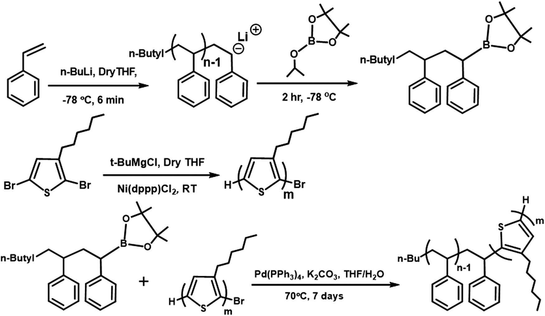 | ||
| Scheme 1 Synthesis routes and molecular structures of the block copolymer P3HT-b-PS. | ||
The polystyrene block with pinacol boronic ester (PS-B(OR)2) as the end functional group was synthesized by the living polymerization method, in which polymer termination was carried out by the addition of isopropyl pinacolyl borate in the final stage. Subsequently, the formation of the pinacol boronic ester group on the PS chain ends was confirmed via1H NMR spectra, in which the signals for the end group (–C(CH3)2) resonated at 0.92 and 1.2 ppm in CDCl3. The number average molecular weight (Mn) and polydispersity (PDI) were determined as 7340 Dalton and 1.23, respectively, by gel permeation chromatography (GPC).
P3HT with the bromo terminal group (P3HT-Br) was synthesized by the Grignard metathesis method. Mn and PDI were also determined by GPC as 9,700 Dalton and 1.09, respectively. The end group-Br in P3HT-Br was identified by 1H NMR spectra with two small triplets appearing at δ = ∼2.6 ppm, as also reported by McCullough et al.28,29 Then, P3HT-Br was coupled with PS-B(OR)2via the Suzuki coupling reaction, with the equivalent mole ratio being 1:5 for the reaction to obtain the di-block copolymer. The formation of the block copolymer from two different blocks was also indicated by the GPC results (Fig. 1). The increase of Mn of the resulting block copolymer relative to its two components is shown in the GPC chromatogram (Mn = 11520 Dalton, PDI = 1.20). The GPC result indicates that P3HT-Br prefers to couple with the short-chain of PS-B(OR)2 due to the higher probability of coupling reaction between shorter chains. The excess PS was removed in the purification step using acetone, and the block copolymer in the GPC chromatogram shows the absence of the polystyrene homopolymer peak from 15 to 16 min in the elution time. The Fourier-transform infrared spectroscopy (FTIR) of the P3HT-Br shows the presence of C–Br stretching vibration at 690 (cm−1). However, in the present block copolymer sample, this stretching vibration is absent, indicating the absence of unreacted P3HT-Br in the sample as shown in Fig. S2 (ESI†). The composition of the copolymer was determined from the UV-Vis spectra via calculating the spectral area (from 300 to 565 nm) at an equal concentration of polymers in chloroform (1 mg mL−1) (Fig. S3a, ESI†). The area ratio of P3HT-b-PS to P3HT-Br was 72:100, thus reflecting that the weight ratio of P3HT:PS in the copolymer was 72:28. Thus, this information regarding the weight ratio of P3HT:PS was confirmed with our inference about the reaction priority of P3HT-Br with the short chains of PS. In addition, the π–π conjugation in the P3HT block in the copolymer was not affected by the presence of the PS block, as shown by the overlapping of the normalized spectra of the two blocks (P3HT and PS) at their absorption maxima (Fig. S3b, ESI†).
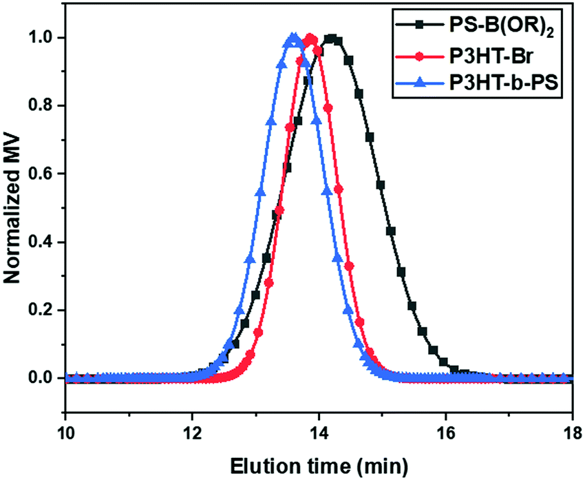 | ||
| Fig. 1 Gel permeation chromatograms of PS-B(OR)2, P3HT-Br, and P3HT-b-PS. | ||
2.2 Hybrid quantum dot solar cell with the block copolymer P3HT-b-PS
The morphology of the active layers prior to ligand exchange to BDT was investigated via SEM for avoiding crack formation due to the exchange that could lead to complication in the analysis of morphology, which is composed of various weight ratios of P3HT:P3HT-b-PS ranging from 1:0 to 0:1 with the weight ratio of the total polymer to QD being retained at 1:20. The SEM images of the active layers are shown in Fig. 2. Among these images, the dark regions are recognized as polymer-rich regions since the electron density of the polymer was lower than that of PbS QDs, leading to a lower reflecting electron density, while the bright/grey regions are referred to as PbS QD-rich regions. Fig. 2a shows the aggregation of P3HT chains causing the formation of nearly isolated domains, with the width varying from 120 to 390 nm. However, QD-rich domains were noodle-like with a large extent of interconnection, and their widths vary from 293 to 583 nm. In the case of P3HT-b-PS with PbS QDs (Fig. 2f), the polymer-rich domains, with the width ranging from 68 to 220 nm, were interconnected, and the QD-rich domains also show the formation of continuous domains though their sizes were small (only from 242 nm to 396 nm); thus, this blend gives a bi-continuous network morphology. Such bicontinuous network morphology was found for the first time and can be explained by the mutual miscibility of three components, P3HT, PS, and OA-capped PbS QDs, as indicated in our previous study of mesoscale simulation using the coarse-grained model.27 By coupling the PS block with P3HT, the miscibility of the polymer with OA-capped PbS QDs improved because the solubility parameter (δ) of polystyrene (δ = 8.05 (cal cm−3)1/2) was close to that of the oleic acid (OA, δ = 8.25 (cal cm−3)1/2) compared with that of P3HT (δ = 9.05 (cal cm−3)1/2, which led to the microphase separation of PS and P3HT as well as an improvement in the miscibility of PS-phase with QD-phase.27 Note that in the determination of δ of OA in our previous simulation, the COOH group in OA was replaced by the CH3 group since the COOH group of the OA ligand was attached to the surface of PbS QDs and was not in contact with the polymer chains, thus showing weak interactions between PbS QDs and the polystyrene phase.31
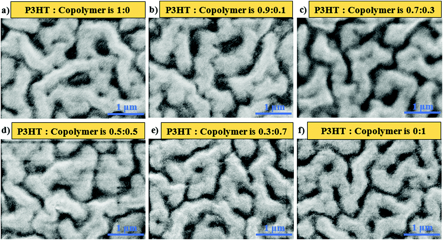 | ||
| Fig. 2 The SEM image of the polymer:PbS QD film at the weight ratio of 1:20 with various weight ratios of P3HT and P3HT-b-PS in polymer phases. | ||
To further confirm the formation of a bi-continuous network morphology, we performed the hole mobility measurement for the blend of P3HT:QD and P3HT-b-PS:QD at the weight ratio of 1:20 using the hole-only device having the structure ITO/PEDOT:PSS/polymer:OA-PbS QD/MoO3/Al, in which the active layer was a thin film of P3HT:PbS QD or P3HT-b-PS:PbS QD of 120 nm thickness. The hole currents versus the applied voltage plots of the blend are shown in Fig. 3. The hole-current profile of P3HT-b-PS:PbS QD was observed to be higher than that of P3HT:PbS QD by the factor of 2.4 at 1 × 10⁵ Vcm−1, indicating the formation of a more efficient hole transport channel by using P3HT-b-PS though the content of the conductive component P3HT was 28% less than that of the device having only homopolymer P3HT. Thus, this result further supports that the P3HT-b-PS system gives better quality of the bi-continuous network morphology than the P3HT system.
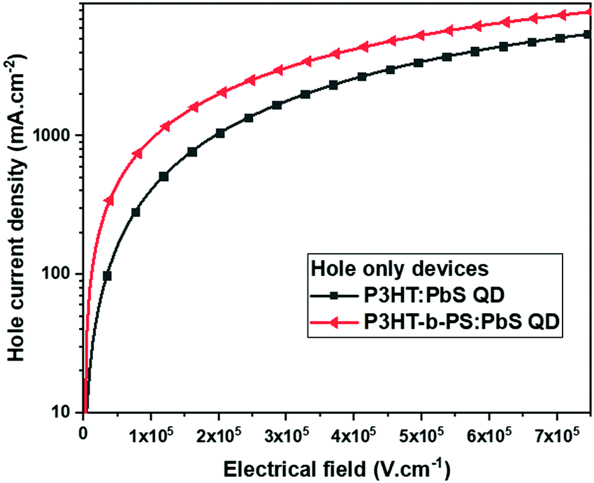 | ||
| Fig. 3 Hole current density versus electrical field of the device having different active layers in the hole-only device: ITO/PEDOT:PSS/polymer:OA-PbS QD/MoO3/Al. | ||
To investigate the effect of the block copolymer, P3HT-b-PS, on the device performance, we fabricated the device with the structure ITO/PEDOT:PSS(40 nm)/polymer:BDT-PbS (120 nm)/BDT-PbS (30 nm) LiF (0.6 nm)/Al (100 nm), as illustrated in Scheme 2. Since device performance of HQDSC usually depends on the weight ratio of the polymer and QDs,25,26 we first investigated the weight ratio dependency of P3HT:PbS QD-based solar cells, and the results are presented in Fig. S4 and Table S1 (ESI†). The values of all the parameters, VOC, JSC, and FF, initially increased monotonically when the content of P3HT in P3HT:PbS QDs decreased from the ratio 1:5 to 1:20, but then dropped at 1:25. Thus, the optimal weight ratio was 1:20, at which the values of VOC, JSC, and FF were 0.50 V, 13.68 mA cm−2, and 38.0%, respectively, thus obtaining the optimal PCE of 2.58%. The thermal annealing of the active layer has been proven to be an effective strategy to increase the electrical conductivity of the active layer.32,33 Here, we investigated HQDSC with the weight ratio of 1:20 at different annealing temperatures from room temperature to 225 °C to search for the optimal annealing condition. The result of device performances (J–V curves) are shown in Fig. S5 (ESI†), and the J–V characteristic parameters are listed in Table S2 (ESI†). Both the VOC and JSC values were found to slightly increase with the increase in annealing temperature up to 175 °C, and the PCE reached 3.52%, while when the annealing temperature was increased further to 225 °C, both the VOC and JSC values slightly decreased, leading to a lower PCE of 3.45%. In the following studies on device performances of the devices with various compositions of the active layer, the optimal polymer to the QD weight ratio of 1:20 and annealing temperature of 175 °C was used.
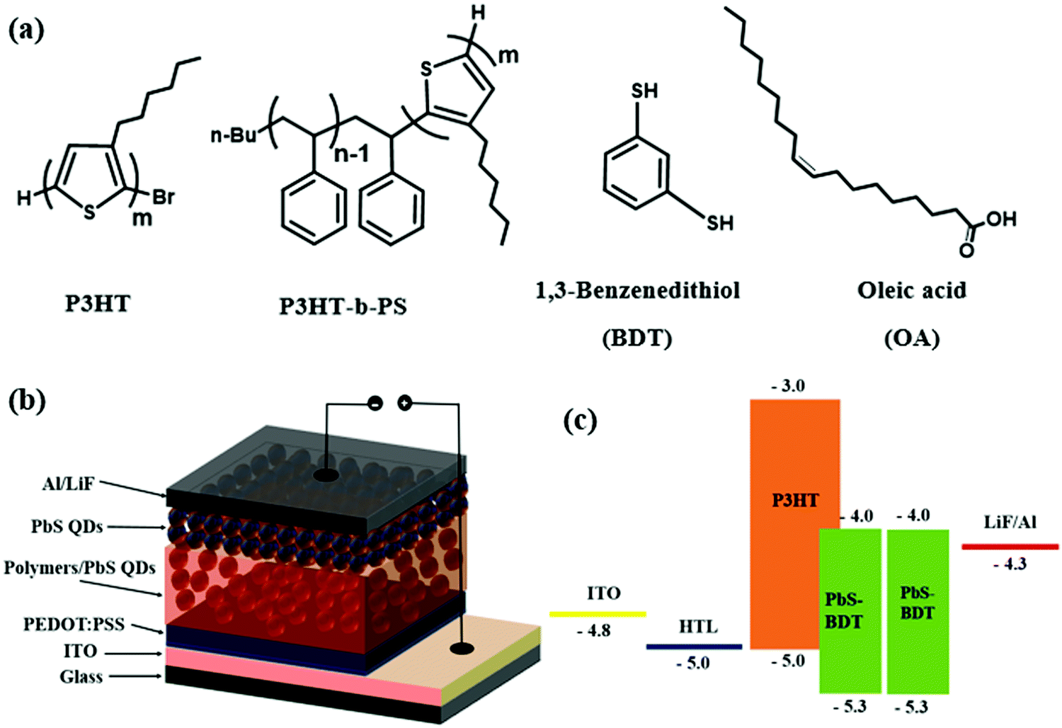 | ||
| Scheme 2 (a) Chemical structures of polymers and ligands, (b) the schematic of the hybrid photovoltaic device, and (c) ligands and energy diagram of the quantum dot hybrid solar cell. | ||
The J–V curves of the devices with various ratios of P3HT to P3HT-b-PS, as a donor, are shown in Fig. 4, and the characteristic device parameters are listed in Table 1. The P3HT-b-PS device gives the improved current density of 16.58 mA cm−2 relative to that of the P3HT device (15.81 mA cm−2) due to better quality of the bi-continuous network morphology for more efficient charge transport and collection. In addition, VOC and FF also slightly improved to 0.53 V and 47.7% from 0.52 V and 44.6%, respectively. Thus, the PCE was improved to 4.18% from 3.66% even though the content of the photo-active component P3HT in the block copolymer was less. The parameters RSH and RS, referring to the leakage current and bulk resistance, respectively, were calculated from the current density–voltage curves.34 The corresponding RSH of the P3HT-b-PS device increased to 191.2 Ω·cm2 relative to that of the P3HT device (140.0 Ω·cm2), which indicates that the leakage current in the former was higher than that in the latter. In contrast, the RS of the P3HT-b-PS device (12.2 Ω·cm2) was slightly lower relative to that of the P3HT device (12.7 Ω·cm2). Thus, the device performance results are in good agreement with the morphology of the active layers and hole current profile measurement.
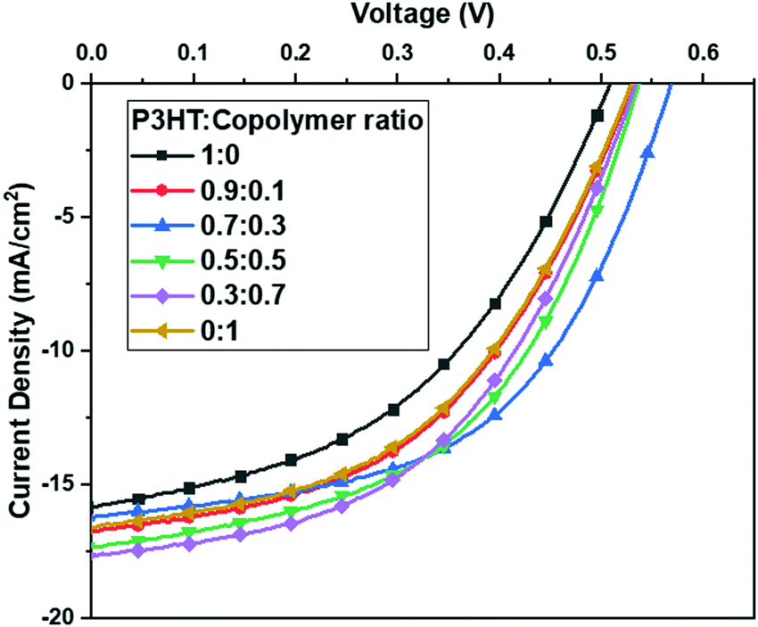 | ||
| Fig. 4 Current density–voltage (J–V) characteristics of the devices with Polymer:BDT-PbS as the active layer at the weight ratio of 1:20 and various contents of the block copolymer. | ||
:PbS QD devicesa at 1:20 weight ratio and various contents of the block copolymer
| Polymer ratio (P3HT:P3HT-b-PS)b |
V OC (V) | J SC (mA cm−2) | FF (%) | PCE (%) | R SH (Ω·cm2) | R S (Ω·cm2) | Width of polymer domains (nm) |
|---|---|---|---|---|---|---|---|
| a The device structure is ITO/PEDOT: PSS(40 nm)/polymer: BDT-PbS(120 nm)/BDT-PbS(30 nm)LiF(0.6 nm)/Al(100 nm). b The polymer ratio is referred to the weight ratio of P3HT to P3HT-b-PS. | |||||||
| 1:0 |
0.52 | 15.81 | 44.6 | 3.66 | 140.0 | 12.7 | 120–390 |
| 0.9:0.1 |
0.53 | 16.75 | 47.7 | 4.24 | 194.6 | 11.6 | 75–390 |
| 0.7:0.3 |
0.57 | 16.21 | 53.2 | 4.91 | 256.6 | 10.4 | 95–341 |
| 0.5:0.5 |
0.54 | 17.29 | 50.7 | 4.70 | 183.5 | 9.2 | 87–245 |
| 0.3:0.7 |
0.53 | 17.61 | 49.0 | 4.60 | 212.5 | 10.7 | 64–256 |
| 0:1 |
0.53 | 16.58 | 47.7 | 4.18 | 191.2 | 12.2 | 68–220 |
2.3 Influence of blend ratio of P3HT to P3HT-b-PS as the donor
It is known up to this stage that the blend of the block copolymer P3HT-b-PS with QD gives a high-quality bi-continuous network morphology, which provides separated charge transport channels for electrons and holes. However, the PS block was a non-conjugated polymer and did not absorb sunlight to generate exciton. To further improve the performance, we added P3HT into the block copolymer/QD blend for absorbing more sunlight and subsequently investigated if the bi-continuous network morphology was retained. First, to examine the morphological changes, four different ratios (0.9:0.1, 0.7:0.3, 0.5:0.5, and 0.3:0.7) of the blends of P3HT and P3HT-b-PS were chosen, and each blend was mixed with PbS QDs in the weight ratio of polymer:QDs = 1:20 in the solution, which are acting as the active layer. The SEM images of each blend mixed with PbS QDs are shown in Fig. 2b–e, and in all the samples continuous QD-rich regions (the bright-grey region) are observed. The width ranges of polymer-rich domains for the blends are given in Table 1. For the polymer-rich domains at a 1:0 ratio of P3HT:P3HT-b-PS (that is P3HT only), the domain widths were found to vary from 120 nm to 390 nm, with a low extent of domain interconnection. As the content of P3HT-b-PS was increased, the extent of interconnection among the polymer-rich domains was promoted from the nearly isolated domains to continuous networks, while the QD-rich domains always remain interconnected. Also, the width range of polymer-rich domains tends to decrease with the increase in the content of P3HT-b-PS.
Further, we fabricated HQDSCs at the weight ratio of 1:20 of the polymer to QDs and various weight ratios of P3HT to P3HT-b-PS with the device configuration: ITO/PEDOT:PSS (40 nm)/polymer:PbS QD (120 nm)/PbS QD (30 nm)/LiF (0.6 nm)/Al (100 nm). The device performances (current density versus voltage) are shown in Fig. 4, and the characteristic parameters are listed in Table 1. VOC exhibited slight composition dependency, with the optimal value being 0.57 V at the ratio of 0.7:0.3 of P3HT:P3HT-b-PS. JSC and FF both exhibited an improvement with the increase in the block copolymer content. Consequently, an optimal PCE value was obtained at the ratio of 0.7:0.3. Thus, these observations indicate that the addition of P3HT into the block copolymer could lead to the generation of more excitons but might cause a drop in the quality of the bi-continuous network morphology. Further, the RSH and RS dependency on the polymer composition shows higher and lower values at the optimal ratio of 0.7:0.3, respectively, which are beneficial to the device performance due to the presence of lower series resistance and high shunt resistance at this composition.
The device performance results indicate that the formation of bi-continuous charge transport channels in the active layer was still retained even when P3HT was added into the block copolymer. At the optimal ratio of 0.7:0.3 of P3HT to P3HT-b-PS, PCE significantly improved from 3.66% to 4.91% because the high quality bi-continuous network morphology in the active layer was still retained, and the content of the photoactive P3HT was increased. To the best of our knowledge, this performance is the best among the reported state-of-the-art P3HT/QD systems, as summarized in Table 2.
| HTLa | Active layer | Ligand | V OC (V) | J SC (mA cm−2) | FF (%) | PCE (%) | Ref. |
|---|---|---|---|---|---|---|---|
| a HTL: hole transport layer. | |||||||
| PEDOT:PSS | P3HT:P3HT-b-PS:PbS QDs (0.7:0.3:20) |
BDT | 0.57 | 16.21 | 53.2 | 4.91 | This work |
| PEDOT:PSS | P3HT:PbS QD:MWCNTs (20:4:1) |
OLA (oleylamine) | 0.54 | 10.81 | 54.0 | 3.03 | 35 |
| PEDOT:PSS | P3HT:PbS QD (1:9) |
MPA (3-mercaptopropionic acid) | 0.56 | 10.8 | 50 | 3.0 | 36 |
| MoO3 | P3HT:CdTe QD (1:24) |
MA (2-mercaptoethylamine hydrochloride) | 0.54 | 16.95 | 47.2 | 4.32 | 25 |
3. Conclusion
A desirable bi-continuous network morphology was obtained experimentally for the first time in polymer/QD systems. For the blend system studied, the block copolymer P3HT-b-PS with PbS QD does form such morphology due to efficient mixing between the PS block and OA-PbS QDs, as predicted by the mesoscopic simulation in our previous report, which leads to the improved PCE (4.18%) relative to the homopolymer P3HT (3.66%) even though the block copolymer system contains lesser amount of photo-active component, i.e., P3HT. We also found that the addition of P3HT into P3HT-b-PS does not disturb the desired morphology significantly. At the weight ratio of 0.7:0.3 of P3HT:P3HT-b-PS, the PCE was further improved to 4.91% due to an increase in the content of the photo-active component (P3HT) while the desired morphology was still retained. The value of PCE (4.91%) obtained in this study was slightly higher than the recorded PCE (4.32%) in the P3HT:QD system. Thus, the present methodology should also be applicable to other photo-active polymers/QD systems.
4. Experimental
Synthesis
The detailed synthesis and characterization of the materials are described in the ESI.†Device fabrication and measurements
The fabrication procedure for HQDSCs is as follows: an indium tin oxide (ITO) glass substrate was cleaned sequentially with an aqueous solution of the detergent aqueous solution, deionized water, acetone, and isopropyl alcohol. The cleaned ITO glass was then treated with oxygen plasma at a power of 50 W and a pressure of 193 mTorr for 5 min in a plasma generator chamber of the parallel electrode type. Poly(styrene sulfonic acid)-doped poly(3,4-ethylenedioxythiophene) (PEDOT:PSS) was then spin-coated on the treated ITO substrate. After drying for 15 min at 140 °C, a blend solution of P3HT (or P3HT-b-PS or its blend with P3HT) and OA capped-PbS in chloroform with a specific weight ratio was spin-coated on the PEDOT:PSS layer. The post-ligand-exchange was carried out by spin-coating the as-prepared film with a solution of 0.5 vol% BDT in acetonitrile for 30 s for replacing OA, and then rinsed with pure acetonitrile twice to remove the excess BDT and OA. Subsequently, a thin pure PbS QD with the OA ligand layer was deposited onto the blend film from a 20 mg mL−1 solution in octane, and then ligand was exchanged with BDT, and cleaning was performed, as mentioned above. The device was then baked at 175 °C for 20 min in a glovebox. Finally, a thin lithium fluoride (0.6 nm) and aluminum (100 nm) as the cathode were thermally deposited through a shadow mask at a pressure of less than 2 × 10⁻⁶ Torr. The active area of the device was about 1.5 mm2. Current–voltage characteristics were recorded using a Keithley 2400 (I–V) digital source meter under a simulated AM 1.5G solar irradiation at 100 mW cm−2.Author contributions
The manuscript was written through contributions of all authors. All authors have given approval to the final version of the manuscript.Conflicts of interest
The authors declare no competing financial interest.Acknowledgements
The financial support by the Ministry of Science and Technology and Ministry of Education for the financial aid through projects MOST-105-2221-E-007-134, MOST-104-2633-M-007-001, MOST 106-2923-E007-001-MY3, and MOE-105N506CE1); the financial support by Russian Foundation for Basic Research (Project RFBR No. 17-53-52009); and Ministry of Science and Higher Education of the Russian Federation are highly appreciated.References
- N. Razgoniaeva, M. Yang, C. Colegrove, N. Kholmicheva, P. Moroz, H. Eckard, A. Vore and M. Zamkov, Chem. Mater., 2017, 29, 7852–7858 CrossRef CAS.
- X. Gong, Z. Yang, G. Walters, R. Comin, Z. Ning, E. Beauregard, V. Adinolfi, O. Voznyy and E. H. Sargent, Nat. Photonics, 2016, 10, 253–257 CrossRef CAS.
- Y. Wang, K. Lu, L. Han, Z. Liu, G. Shi, H. Fang, S. Chen, T. Wu, F. Yang, M. Gu, S. Zhou, X. Ling, X. Tang, J. Zheng, M. A. Loi and W. Ma, Adv. Mater., 2018, 30, 1–8 CAS.
- J. Choi, Y. Kim, J. W. Jo, J. Kim, B. Sun, G. Walters, F. P. García de Arquer, R. Quintero-Bermudez, Y. Li, C. S. Tan, L. N. Quan, A. P. T. Kam, S. Hoogland, Z. Lu, O. Voznyy and E. H. Sargent, Adv. Mater., 2017, 29, 1–5 Search PubMed.
- P. R. Brown, D. Kim, R. R. Lunt, N. Zhao, M. G. Bawendi, J. C. Grossman and V. Bulović, ACS Nano, 2014, 8, 5863–5872 CrossRef CAS.
- T. P. Osedach, N. Zhao, T. L. Andrew, P. R. Brown, D. D. Wanger, D. B. Strasfeld, L.-Y. Chang, M. G. Bawendi and V. Bulović, ACS Nano, 2012, 6, 3121–3127 CrossRef CAS.
- M. I. Nugraha, R. Häusermann, S. Z. Bisri, H. Matsui, M. Sytnyk, W. Heiss, J. Takeya and M. A. Loi, Adv. Mater., 2015, 27, 2107–2112 CrossRef CAS.
- Z. Sun, Z. Liu, J. Li, G. Tai, S.-P. Lau and F. Yan, Adv. Mater., 2012, 24, 5878–5883 CrossRef CAS.
- S. A. McDonald, G. Konstantatos, S. Zhang, P. W. Cyr, E. J. D. Klem, L. Levina and E. H. Sargent, Nat. Mater., 2005, 4, 138–142 CrossRef CAS.
- M. Yuan, M. Liu and E. H. Sargent, Nat. Energy, 2016, 1, 16016 CrossRef CAS.
- R. J. Ellingson, M. C. Beard, J. C. Johnson, P. Yu, O. I. Micic, A. J. Nozik, A. Shabaev and A. L. Efros, Nano Lett., 2005, 5, 865–871 CrossRef CAS.
- F. W. Wise, Acc. Chem. Res., 2000, 33, 773–780 CrossRef CAS.
- J. M. Luther, J. Gao, M. T. Lloyd, O. E. Semonin, M. C. Beard and A. J. Nozik, Adv. Mater., 2010, 22, 3704–3707 CrossRef CAS.
- S.-W. Baek, S.-H. Lee, J. H. Song, C. Kim, Y.-S. Ha, H. Shin, H. Kim, S. Jeong and J.-Y. Lee, Energy Environ. Sci., 2018, 11, 2078–2084 RSC.
- C. H. M. Chuang, P. R. Brown, V. Bulović and M. G. Bawendi, Nat. Mater., 2014, 13, 796–801 CrossRef CAS.
- B. Sun, A. Johnston, C. Xu, M. Wei, Z. Huang, Z. Jiang, H. Zhou, Y. Gao, Y. Dong, O. Ouellette, X. Zheng, J. Liu, M.-J. Choi, Y. Gao, S.-W. Baek, F. Laquai, O. M. Bakr, D. Ban and E. H. Sargent, Joule, 2020, 4, 1542–1556 CrossRef CAS.
- Y. Liu, G. Shi, Z. Liu and W. Ma, Nanoscale Horiz., 2021, 6, 8–23 RSC (Minireview), Advance Article.
- N. C. Greenham, X. Peng and A. P. Alivisatos, Phys. Rev. B: Condens. Matter Mater. Phys., 1996, 54, 17628–17637 CrossRef CAS.
- I. Gur, N. A. Fromer, C.-P. Chen, A. G. Kanaras and A. P. Alivisatos, Nano Lett., 2007, 7, 409–414 CrossRef CAS.
- J. Seo, M. J. Cho, D. Lee, A. N. Cartwright and P. N. Prasad, Adv. Mater., 2011, 23, 3984–3988 CrossRef CAS.
- S. Dayal, N. Kopidakis, D. C. Olson, D. S. Ginley and G. Rumbles, Nano Lett., 2010, 10, 239–242 CrossRef CAS.
- Z. Liu, J. Yuan, S. A. Hawks, G. Shi, S.-T. Lee and W. Ma, Sol. RRL, 2017, 1, 1600021 CrossRef.
- J. Yuan, A. Gallagher, Z. Liu, Y. Sun and W. Ma, J. Mater. Chem. A, 2015, 3, 2572–2579 RSC.
- K. Ji, J. Yuan, F. Li, Y. Shi, X. Ling, X. Zhang, Y. Zhang, H. Lu, J. Yuan and W. Ma, J. Mater. Chem. A, 2020, 8, 8104–8112 RSC.
- S. Yao, Z. Chen, F. Li, B. Xu, J. Song, L. Yan, G. Jin, S. Wen, C. Wang, B. Yang and W. Tian, ACS Appl. Mater. Interfaces, 2015, 7, 7146–7152 CrossRef CAS.
- Z. Liu, Y. Sun, J. Yuan, H. Wei, X. Huang, L. Han, W. Wang, H. Wang and W. Ma, Adv. Mater., 2013, 25, 5772–5778 CrossRef CAS.
- P. Komarov, P. Baburkin, V. Ivanov, S.-A. Chen and A. Khokhlov, Mol. Syst. Des. Eng., 2019, 4, 390–395 RSC.
- M. C. Iovu, E. E. Sheina, R. R. Gil and R. D. McCullough, Macromolecules, 2005, 38, 8649–8656 CrossRef CAS.
- J. Liu and R. D. McCullough, Macromolecules, 2002, 35, 9882–9889 CrossRef CAS.
- Z. Gu, Y. Tan, K. Tsuchiya, T. Shimomura and K. Ogino, Polymers, 2011, 3, 558–570 CrossRef CAS.
- P. V. Komarov, P. O. Baburkin, V. A. Ivanov, Y.-L. Li, S.-A. Chen and A. R. Khokhlov, Sol. RRL, 2020, 4(11), 2000352 CrossRef CAS.
- H. Wang, S. Yang, Y. Wang, J. Xu, Y. Huang, W. Li, B. He, S. Muhammad, Y. Jiang, Y. Tang and B. Zou, Org. Electron., 2017, 42, 309–315 CrossRef CAS.
- Y. Cao, A. Stavrinadis, T. Lasanta, D. So and G. Konstantatos, Nat. Energy, 2016, 1, 16035 CrossRef CAS.
- M.-Y. Lin, C.-Y. Lee, S.-C. Shiu, I.-J. Wang, J.-Y. Sun, W.-H. Wu, Y.-H. Lin, J.-S. Huang and C.-F. Lin, Org. Electron., 2010, 11, 1828–1834 CrossRef CAS.
- D. Wang, J. K. Baral, H. Zhao, B. A. Gonfa, V.-V. Truong, M. A. El Khakani, R. Izquierdo and D. Ma, Adv. Funct. Mater., 2011, 21, 4010–4018 CrossRef CAS.
- C. Giansante, R. Mastria, G. Lerario, L. Moretti, I. Kriegel, F. Scotognella, G. Lanzani, S. Carallo, M. Esposito, M. Biasiucci, A. Rizzo and G. Gigli, Adv. Funct. Mater., 2015, 25, 111–119 CrossRef CAS.
Footnote |
| † Electronic supplementary information (ESI) available. See DOI: 10.1039/d0ma00770f |
| This journal is © The Royal Society of Chemistry 2021 |