
 Open Access Article
 This Open Access Article is licensed under a
 Creative Commons Attribution 3.0 Unported Licence
Progress and challenges in photocatalytic ammonia synthesis
Qing
Han†
 ab,
Haimiao
Jiao†
b,
Lunqiao
Xiong
b and
Junwang
Tang
*b
ab,
Haimiao
Jiao†
b,
Lunqiao
Xiong
b and
Junwang
Tang
*b
aKey Laboratory of Cluster Science, Ministry of Education of China, Key Laboratory of Photoelectronic/Electrophotonic Conversion Materials, School of Chemistry and Chemical Engineering, Beijing Institute of Technology, Beijing 100081, China
bDepartment of Chemical Engineering, University College London, London WC1E 7JE, UK. E-mail: junwang.tang@ucl.ac.uk
First published on 3rd November 2020
Abstract
Photocatalytic ammonia (NH3) synthesis from N2 and water driven by solar energy is a sustainable and environmentally friendly technology, which has gained considerable attention in recent years. In this review, the recent development in the fundamental understanding of photocatalytic NH3 synthesis and the methods of precise NH3 detection are summarized. More importantly the strategy for surface engineering and interface engineering of photocatalysts toward photocatalytic NH3 production has been thoroughly analyzed with the aim to stimulate critical thinking about the effective methodology for catalyst modification instead of exploring new materials. At the end the challenges and a few concerns are raised from the current reports and future perspectives in this research field are discussed targeting to clarify the reliability and reproducibility of the photochemical process and to direct the future research direction, such as flow reactor design and in-depth understanding of the underlying reaction pathway.
 Qing Han | Qing Han is an Assistant Professor of Chemistry at Beijing Institute of Technology (Beijing, China). She received her PhD in chemistry from Beijing Institute of Technology. Her research focuses on (i) the design and synthesis of nanocatalysts for photocatalysis and electrocatalysis, and (ii) device fabrication of carbon-based nanomaterials for energy conversion. |
 Haimiao Jiao | Haimiao Jiao received his BEng and MSc in Chemical Engineering from Tianjin University and Imperial College London, respectively. Currently, he is a PhD student in Prof. Junwang Tang's group at the Department of Chemical Engineering, University College London. His research interests focus on photocatalytic hydrogen production from methanol and nitrogen reduction. |
 Lunqiao Xiong | Lunqiao Xiong received his BSc and MEng in Materials Science from Xi’an Jiaotong University and Tsinghua University, respectively. At present, he is a PhD student in Prof. Junwang Tang's group at the UCL Department of Chemical Engineering. His current research focuses on photocatalytic selective oxidation. |
 Junwang Tang | Junwang Tang is a Fellow of European Academy of Sciences, Fellow of the Royal Society of Chemistry and Professor of Materials Chemistry and Engineering in the Department of Chemical Engineering at University College London. His research interests encompass photocatalytic small molecule activation (e.g. CH4, N2, H2O, CO2 and C6H6) and microwave catalysis (plastic chemical recycling), together with microwave-intensified chemical processes. He has also received many awards, the latest of which is the IChemE Business Start-Up Award 2019. He also sits on the editorial/advisory board of several international journals, e.g. the Editor of Applied Catalysis B, Editor-in-Chief of Journal of Advanced Chemical Engineering, and Associate Editor of Chin. J. Catal. and Asia-Pacific Journal of Chemical Engineering. |
Introduction
Ammonia (NH3) has been regarded as one of the most important chemical products as feedstock for fertilizers and for various chemicals.1,2 The production of NH3 plays a prominent role in global economy with an annual yield of more than 200 million tons.3 The industrial synthesis of NH3 is dominated by the revolutionary Haber–Bosch process, in which pure H2 and N2 are reacted under high pressure at high temperature over Fe-based catalysts, which consumes 1–2% of total global fossil fuels and releases around 300 million tons of planet-warming CO2 into the atmosphere annually.4–7 The development of environmentally friendly, sustainable strategies with high efficiency of NH3 production under mild conditions is highly desirable but challenging.Currently, there are a few green routes reported for ammonia synthesis. One is biological nitrogen fixation which mostly relies on diazotrophs in nature.8 Another one is electrochemical reduction of N2, which uses electricity to produce NH3.9,10 Compared with the stringent conditions of biological nitrogen fixation and the requirement of highly conductive electrolytes and costly electrodes used in electrochemical reduction of N2, photocatalytic ammonia synthesis using sustainable solar energy operated under either aqueous or gaseous conditions is rather different, maybe also economical, from the other methods. If the efficiency of solar driven NH3 synthesis could be dramatically improved, this method has strong potential to replace the current Haber–Bosch process. Photocatalytic reduction of N2 to produce NH3 by utilizing photocatalysts and water, driven by renewable solar energy, has huge potential, and thereby is very significant.11–17 Since the seminal work of Schrauzer and Guth in 1977,17 in which the potential of the TiO2 photocatalyst for N2 reduction with water and N2 was revealed, various semiconductors have been studied for the photocatalytic production of NH3, such as ZnO, Fe2O3, Ga2O3, W18O49, BiOBr, BiOCl, CdS, layered double hydroxides, polymeric carbon nitride and so on.18–25 The main challenges for the photocatalytic synthesis of NH3 are the chemical adsorption and activation of N2. To boost the efficiency of NH3 photosynthesis, the exploitation of highly active photocatalytic materials is crucial. Through surface/interface engineering of various photocatalysts, the photocatalytic reaction pathways can be modulated, therefore enhancing the N2 reduction reaction activity.
Complementary to other reviews in which different photocatalysts are summarized,6,13,18,19,22 this crucial review tries to avoid simply listing a large population of materials and mainly concentrates on recent advances and understanding in two fast moving areas, i.e. surface engineering and interface engineering, which have been proved to be efficient strategies to improve most photocatalysts’ activity for NH3 synthesis, including defect engineering, morphology engineering, cocatalyst loading, and junction structure. The materials stated here are representative and highly efficient. Thus, this review aims at providing a comprehensive understanding of the rational design of highly efficient photocatalysts for N2 photoreduction. Apart from this, the recent understanding of the photocatalytic mechanism of NH3 synthesis and the methods to precisely evaluate the catalytic performance of a photocatalyst in NH3 synthesis will be discussed. Future research directions for further development of the photocatalytic synthesis of NH3 and some concerns will be highlighted at the end.
Photocatalytic mechanism of NH3 synthesis
By mimicking the natural process of photosynthesis, researchers intend to convert solar energy, N2 and water to NH3 by using photocatalysts. The overall reaction is listed as follows:| 2N2 + 6H2O → 4NH3 + 3O2 |
In this artificial photosynthesis, there are two interlinked conversion processes, water splitting and N2 reduction reaction (NRR).26 As shown in Fig. 1a, upon light irradiation, photoinduced electrons generated from photocatalysts populate the conduction band, leaving holes in the valence band. Subsequently, the escaped electrons diffuse across to the reactive sites on the surface of photocatalysts. The adsorbed N2 and H2O are catalyzed by these electrons and holes into NH3 and O2, respectively, along with the generation of the byproduct H2. Thus the key point for this process is not only to design a highly active photocatalyst but also to achieve high selectivity to NH3 instead of H2 gas as indicated in Fig. 1a.
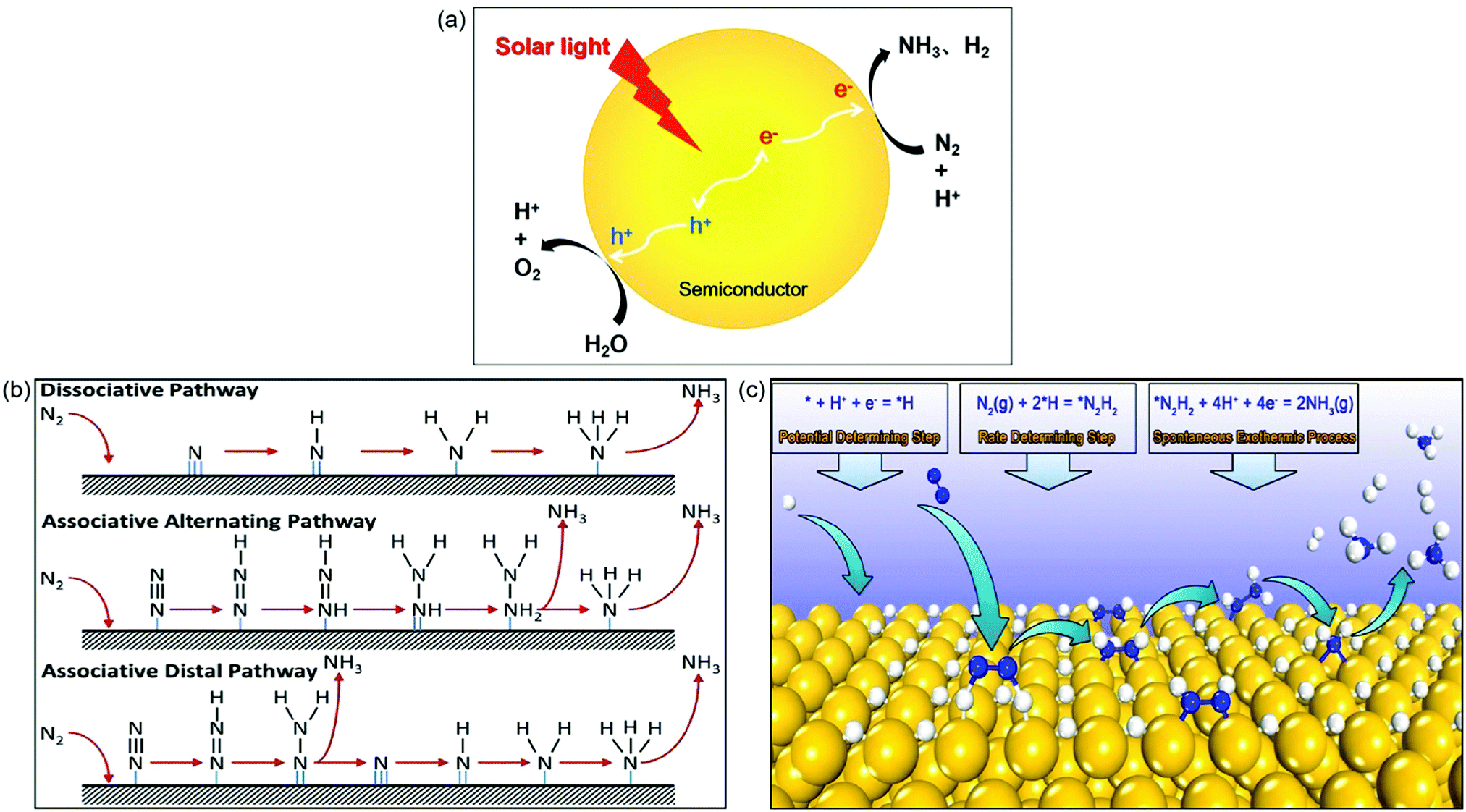 | ||
| Fig. 1 (a) Photocatalytic synthesis of NH3 in water. (b) The proposed mechanisms for photocatalytic N2 reduction consisting of the dissociative pathway, the associative alternating pathway, and the associative distal pathway. Reproduced from ref. 27 with permission from ACS Publication. (c) The proposed mechanism of surface-hydrogenation over noble metal doped photocatalysts for NRR. Reproduced from ref. 28 with permission from ACS Publication. | ||
Up to now, the mechanisms for N2 reduction to NH3 on photocatalysts have been divided into two categories based on the surface adsorption characteristics of catalysts: N-hydrogenation (Fig. 1b) and surface-hydrogenation (Fig. 1c).27,28 For the N-hydrogenation mechanism, there are two different pathways for NRR, dissociative and associative pathways. In the dissociative pathway, the N2 triple bond is broken before hydrogenation, followed by hydrogenation of the N-adatoms into NH3 on the catalyst surface. The Haber–Bosch process is proved to be the dissociative pathway, which requires prohibitively high energy to cleave the N![[triple bond, length as m-dash]](https://www.rsc.org/images/entities/char_e002.gif) N bond. Compared with the dissociative pathway, the associative pathway without the breaking of the NN bond is generally used and accepted far more in the photocatalytic NRR. The nitrogen surface adsorption configuration determines the associative pathways for NRR; as shown in Fig. 1b, the hydrogenation of the adsorbed N2 preferentially occurs at the terminal-site N owing to its relatively low steric hindrance for both the associative alternative pathway and the associative distal pathway. Having generated the first NH3, the other N begins a new hydrogenation circulation to produce a second NH3. It is actually impossible to identify the N2 configurations due to the fact that they are favored equally by the catalysts.
N bond. Compared with the dissociative pathway, the associative pathway without the breaking of the NN bond is generally used and accepted far more in the photocatalytic NRR. The nitrogen surface adsorption configuration determines the associative pathways for NRR; as shown in Fig. 1b, the hydrogenation of the adsorbed N2 preferentially occurs at the terminal-site N owing to its relatively low steric hindrance for both the associative alternative pathway and the associative distal pathway. Having generated the first NH3, the other N begins a new hydrogenation circulation to produce a second NH3. It is actually impossible to identify the N2 configurations due to the fact that they are favored equally by the catalysts.
Recently, a novel surface-hydrogenation mechanism for NRR has been proposed (Fig. 1c),28 in which the adsorbed H+ is reduced into *H first, and then N2 molecules react with surface *H to generate *N2H2, and finally the formed *N2H2 intermediates are reduced into NH3. The first step is the trigger step, which enables the NRR to occur at a low potential. Furthermore, the second step is the rate determining step because it needs to conquer a high energy barrier (Ea) to break the NN bond. The Ea of hydrogen evolution reaction is always lower than that of NRR, and therefore the NH3 production rate is relatively low.
As a complete cycle indicated in Fig. 1a is the ideal process but very challenging, in most cases (or in the majority of the reported cases), a half reaction was investigated in which N2 was reduced to NH3 in the presence of an efficient hole scavenger which was oxidized other than water oxidation. This half reaction is relatively easy and can be used to preliminarily scan different photocatalysts for N2 reduction. Bear in mind that this half reaction has advantages but does not indicate whether the photocatalyst selected is good for a complete cycle as indicated in Fig. 1a. The subsequent discussion will underline this in order to remind the audience of the large difference between a half reaction and the complete cycle.
Determination of NH3
NH3 detection is a necessary subject for the photocatalytic synthesis of NH3, which is of great significance in the design of high performance photocatalysts. There are four common methods of NH3 analysis such as colorimetric assays, 15N isotope labeling, ion chromatography, and in situ infrared spectroscopic measurements.12 The colorimetric assays include Nessler, phenate, and indophenol blue tests for NH3 detection. Among the colorimetric assays, Nessler's reagent has been widely used in NH3 detection due to its advantages of simplicity and low cost.29 However, it is reported that the sacrificial agents (i.e., alcohol) used in the photocatalytic synthesis of NH3 systems can be oxidized to carbonyl compounds, which will disturb NH3 detection in Nessler's reagent detection, thus yielding misleading results. Fig. 2a shows photographs of a solution containing Nessler's reagent and different concentrations of NH3 solutions (0, 1.2, and 4 mg L−1).29 It can be seen that the solution color is turning from light yellow to brown with the increase in the concentration of NH3. When 4 μg L−1 of formaldehyde is added, all the above solutions change into brown, indicating that trace formaldehyde can cause a remarkable color change (Fig. 2b). Therefore, the method of Nessler's reagent is not able to detect NH3 production in the presence of this or similar sacrificial agents. In contrast, the generated carbonyl compounds have no effect on the testing method of ion chromatography (Fig. 2c and d). It is strongly recommended that the colorimetric assay methods have to be accompanied by other methods such as ion chromatography, 15N isotope labeling, and in situ infrared spectroscopic measurements, to avoid such misleading results. Fig. 2e shows the photocatalytic performance of NH3 synthesis via ion chromatography and the indophenol test.30 The UV-vis spectra of the reaction solution containing NH3 exhibit a maximum absorption at 630 nm (inset in Fig. 2e), which is ascribed to the indophenols. The production of NH3 measured by ion chromatography increases with the reaction time (Fig. 2e), consistent with the results obtained by the indophenol test, indicating that indophenol is to some extent reliable. | ||
| Fig. 2 Photographs of NH3 solution with different concentrations (0, 1.2, and 4 mg L−1 from left to right) when (a) mixing with Nessler's reagent and (b) adding 4 μg L−1 formaldehyde into the above ammonia solution with Nessler's reagent. Measured results of NH3 concentration using (c) Nessler's reagent and d) ion chromatography methods. Reproduced from ref. 29 with permission from ACS Publication. (e) The NH3 concentration evolution with time tested by ion chromatography. Inset in (e): UV-vis absorption spectra tested with the indophenol reagent with the characteristic adsorption peak of 630 nm wavelength. Reproduced from ref. 30 with permission from ACS Publication. | ||
Extensive studies on the determination of NH3 have revealed that the indophenol blue method, Nessler's reagent method, and the ion chromatography method are accurate when the concentration of NH3 is less than 500 μg L−1, but the indophenol blue method tends to be less accurate at higher concentrations or under acidic conditions. Besides, the presence of carbonyl compounds from scavengers will enhance light adsorption in Nessler's reagent method, thus leading to an interfered detection of NH3. Thus, to guarantee accuracy and reliability of NH3 quantification, at least two detection methods such as the ion chromatography method and Nessler's reagent method are recommended. Furthermore, because of trace NH3 in the ambient atmosphere, it is necessary to test the isotopically labeled 15N2 to confirm the source of nitrogen in the product.
Strategies to improve photocatalytic efficiency
As mentioned above there are a few reviews summarizing the activity of diverse photocatalysts.6,13,18,19,22 This critical review will not overlap with these reviews, but will only concentrate on the efficient strategies to improve (i) N2 adsorption and (ii) charge separation. Such strategies include surface engineering and interface engineering for NH3 synthesis. The photocatalytic process of NH3 production generally includes four steps, photogeneration of charge carriers followed by their migration to the active sites, N2 chemisorption, surface photo-oxidation and photo-reduction, and the desorption NH3 from photocatalysts. Following the above key steps, photocatalysts can be engineered to greatly promote their catalytic activities toward NH3 synthesis. As steps (ii), (iii) and (iv) all take place on the surface, through the study of surface regulations and interface modulations on the photocatalysts, their photocatalytic performance can be maneuvered. The surface regulations, including defect engineering and morphology engineering, significantly determine the photocatalytic activity because they can promote the surface adsorption and activation of N2.23,31–40,54–57,64–71 The interface modulations, including modification with cocatalysts and semiconductors, greatly affect the charge transfer and separation efficiency.89–101,109–111 We will discuss these factors one by one below. In order to provide an intuitively systematic comparison of photocatalytic N2 reduction systems, we list photocatalysts, reactants, NH3 production rate, in particular the apparent quantum efficiency and detection method as shown in Table 1.| Catalyst | Reaction medium | Scavenger | Light source | Ammonia yield | Apparent quantum efficiency (AQE) | Ammonia detection method | Ref. |
|---|---|---|---|---|---|---|---|
| BiOBr-001-OV | N2/H2O (l) | None | λ > 420 nm | 104.3 μmol g−1 h−1 | 0.23% at 420 nm | Nessler's reagent | 31 |
| JRC-TIO-6 | N2/H2O (l) | 2-PrOH | λ > 280 nm | 2.5 μmol g−1 h−1 | Not reported | Indophenol blue method | 32 |
| CuCr-LDH | N2/H2O (l) | None | Full spectrum | 78.6 μmol g−1 h−1 | 2.4% at 400 nm | Nessler's reagent | 34 |
| ZnAl-LDH | N2/H2O (l) | None | UV-vis | 110 μmol L−1 h−1 | 1.77% at 265 nm, 0.56% at 365 nm | Ion chromatography | 35 |
| V-g-C3N4 | N2/H2O (l) | Methanol | λ > 420 nm | 1.24 mmol h−1 gcat−1 | Not reported | Nessler's reagent | 54 |
| mCNN | N2/ethylene glycol (l) | Ethylene glycol | λ > 400 nm | 3.42 mmol g−1 h−1 | Not reported | Nessler's reagent | 55 |
| SCNNSs | N2/H2O (l) | Methanol | Full spectrum | 5.99 mmol h−1 gcat−1 | Not reported | Nessler's reagent | 56 |
| Mo0.1Ni0.1Cd0.8S | N2/H2O (l) | Ethanol | UV | 3.2 mg h−1 gcat−1 | Not reported | Nessler's reagent | 57 |
| 0.2 wt% Fe-doped TiO2 | N2/H2O (g) | None | UV | 11.6 μmol g−1 h−1 | Not reported | Indophenol blue method | 17 |
| 0.4 wt% Co-doped TiO2 | N2/H2O (l) | None | UV | 6.3 μmol g−1 h−1 | Not reported | Indophenol blue method | 17 |
| 0.4 wt% Cr-doped TiO2 | N2/H2O (l) | None | UV | 0.37 μmol g−1 h−1 | Not reported | Indophenol blue method | 17 |
| 0.4 wt% Mo-doped TiO2 | N2/H2O (l) | None | UV | 6.7 μmol g−1 h−1 | Not reported | Indophenol blue method | 17 |
| Fe-Doped TiO2 | N2/H2O (l) | Ethanol | λ = 254 nm | 1.2 mmol L−1 | Not reported | Nessler's reagent | 64 |
| Fe-Doped SrMoO4 | N2/H2O (l) | None | UV-vis | 93.1 μmol g−1 h−1 | Not reported | Nessler's reagent, indophenol blue method | 65 |
| Fe-Doped BiOCl | N2/H2O (l) | None | Full spectrum | 1.022 mmol g−1 h−1 | 1.8% at 420 nm | Indophenol blue method | 66 |
| Mo-Doped W18O49 | N2/H2O (l) | Na2SO3 | Full spectrum | 195.5 μmol g−1 h−1 | 0.33% at 400 nm | Nessler's reagent, ion chromatography | 67 |
| Cu-Doped TiO2 | N2/H2O (l) | None | Full spectrum | 78.9 μmol g−1 h−1 | 0.08% at 600 nm, 0.05% at 700 nm | Nessler's reagent, ion chromatography | 68 |
| FePt@C3N4 | N2/H2 | None | λ > 400 nm | 63 μg h−1 g−1 | 0.15% between 450 and 500 nm | Colorimetric method, ion chromatography | 72 |
| B-Doped g-C3N4 | N2/H2O (l) | Na2SO3 | λ > 400 nm | 313.9 μmol g−1 h−1 | 0.64% at 420 nm | Nessler's reagent | 73 |
| C-Doped TiO2 | N2/H2O (l) | Methanol | λ > 420 nm | 109.3 μmol g−1 h−1 | 2.4% at 400 nm | Ion chromatography | |
| Bi5O7I-001 | N2/H2O (l) | Methanol | 280–800 nm | 111.5 μmol g−1 h−1 | 5.1% at 365 nm | Nessler's reagent | 77 |
| BiOCl-010 | N2/H2O (l) | Methanol | Full spectrum | 92.4 μmol g−1 h−1 | 4.3% at 254 nm | Nessler's reagent | 78 |
| BiO | N2/H2O (l) | None | Full spectrum | 1226 μmol g−1 h−1 | Not reported | Indophenol blue method | 86 |
| Bi5O7Br-NT | N2/H2O (l) | None | λ > 400 nm | 1.38 mmol g−1 h−1 | 2.3% at 420 nm | Nessler's reagent | 87 |
| eBP NFs | N2/H2O (l) | Na2SO3, Na2S·9H2O | λ = 420 nm | 2.37 mmol g−1 h−1 | Not reported | Nessler's reagent | 88 |
| SiO2/C-RP | N2/H2O (l) | None | Full spectrum | 0.73 μmol h−1 | Not reported | Ion chromatography | 89 |
| Ru-Loaded TiO2 | N2/H2O (l) | Methanol | Full spectrum | 29.4 μmol g−1 h−1 | Not reported | Indophenol blue method | 93 |
| Ru-Loaded TiO2 | N2/H2O (l) | Ethanol | Full spectrum | 56.3 μg h−1 gcat−1 | Not reported | Indophenol blue method | 95 |
| Au/TiO2-OV | N2/H2O (l) | Methanol | λ > 420 nm | 78.6 μmol g−1 h−1 | 0.82% at 550 nm | Indophenol blue method | 96 |
| Ti3C2-P25 | N2/H2O (l) | None | Full spectrum | 10.74 μmol g−1 | Not reported | Ion chromatography | 103 |
| Pt-Loaded ZnO | N2/H2O (l) | Na2SO3 | UV | 860 mmol g−1 h−1 | Not reported | Indophenol blue method | 104 |
| SV-1T-MoS2/CdS | N2/H2O (l) | Methanol | 420–780 nm | 8220.83 μmol L−1 h−1 g−1 | 4.424% under simulated solar light | Nessler's reagent | 105 |
| NiS/CdS | N2/H2O (l) | None | Full spectrum | 2.8 mg L−1 h−1 | 0.76% at 420 nm | Nessler's reagent | 106 |
| Pt-SACs/CTF | N2/H2O (l) | None | 420–780 nm | 171.4 μmol g−1 h−1 | 1.4% at 420 nm | Nessler's reagent | 107 |
| Ru/RuO2/g-C3N4 | N2/H2O (l) | Methanol | Full spectrum | 13.3 μmol g−1 h−1 | Not reported | Ion chromatography | 108 |
| Fe@graphene | N2/H2, 200 °C | None | 200–600 nm | 420 μg gcat−1 h−1 | Not reported | Indophenol blue method | 110 |
| g-C3N4/Bi2MoO6 | N2/H2O (l) | Methanol | λ > 420 nm | 3271 μmol L−1 g−1 | Not reported | Nessler's reagent | 111 |
| TiO2@C/g-C3N4 | N2/H2O (l) | Methanol | λ > 420 nm | 250.6 μmol g−1 h−1 | 0.14% at 420 nm | Nessler's reagent | 112 |
| Bi2MoO6/OV-BiOBr | N2/H2O (l) | None | Full spectrum | 81.0 μmol g−1 h−1 | Not reported | Nessler's reagent | 116 |
Surface regulations
Oxygen vacancies. The introduction of oxygen vacancies (OVs) can effectively facilitate N2 adsorption and activation, as well as induce the generation of mid-gap states to promote the separation of photogenerated charge carriers.31–42 For instance, Zhang et al. reported that BiOBr nanosheets with OVs on the exposed {001} facets (BOB-001-OV) could stretch the N
N bonds from 1.078 Å to 1.133 Å, which gave strong evidence for N2 activation over the OVs.31 Theoretical calculations showed that the OV induced defect states could serve as the electron acceptor (Fig. 3a) to effectively suppress the recombination of electrons/holes and enhance the charge transfer from BOB-001-OV to the N2 molecule. Fluorescence spectroscopy showed that the average lifetime (τ) of BOB-001-OV was 2.15 ns, around two times higher than that of BiOBr without OVs (BOB-001-H, Fig. 3b), proving that the OVs could promote the migration of charge carriers. With the function of OVs, BOB-001-OV showed a NH3 yield rate of 104.3 μmol g−1 h−1 under visible light illumination in the absence of organic scavengers and noble-metal cocatalysts (Fig. 3c), and an apparent quantum efficiency (AQE) of 0.23% at 420 nm. Meanwhile, the amount of generated O2 was stoichiometrically approaching 3/4 of the produced NH3, which proved that water could act as an electron donor to achieve a complete chemical cycle in NH3 photosynthesis.
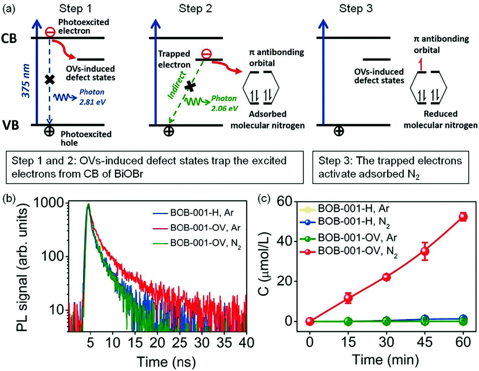 | ||
| Fig. 3 Schematic of the OV-induced enhanced interfacial electron transfer processes over BOB-001-OV. (b) Time-resolved photoluminescence (PL) spectra of BOB-001-OV and BOB-001-H. (c) The photocatalytic NH3 production of BOB-001-OV and BOB-001-H under visible light (λ > 420 nm). Reproduced from ref. 31 with permission from ACS Publication. | ||
Apart from the research on bismuth oxyhalide materials, Shiraishi's group utilized a series of commercial TiO2 to study the effect of OVs on the photoreduction of N2 to NH3.32 A commercial TiO2 of JRC-TIO-6 showed an excellent performance with a steadily increasing NH3 production within 100 h under UV light irradiation in pure water. They proposed that the Ti3+ species formed at the OVs on the surface of TiO2 served as active sites, which could effectively trap the electrons and promote N2 dissociation, resulting in a photocatalytic NH3 production rate of 2.5 μmol h−1.
In order to create the OVs, most studies used oxygen-containing catalysts. In recent years, layered double hydroxide (LDH, Fig. 4a) materials have attracted substantial attention due to their tunable electron structure and low cost.34 Zhang's group firstly used the CuCr-LDH nanosheets (CuCr-NS) with OVs as efficient photocatalysts for NH3 photosynthesis.34 The OVs over CuCr-NS surface were created by the reduction of thickness and the in-plane compressive strain (Fig. 4b). The optimal CuCr-NS exhibited a NH3 production rate of 78.6 μmol g−1 h−1 under full-spectrum irradiation (Fig. 4c), and an AQE of 2.4% at 400 nm. Subsequently, they further reported another work on ZnAl-LDH nanosheets for optimal OVs by incorporating coordinately unsaturated Cuδ+ species.35 The DFT calculations implied that the OVs and Cuδ+ species in ZnAl-LDH could effectively promote N2 adsorption and activation, leading to a remarkable NH3 yield of 110 μmol L−1 h−1 in pure water under UV-vis irradiation. Therefore, the creation of OVs on the surface of photocatalysts paves a way for developing other innovative materials toward photocatalytic N2 reduction.
 | ||
| Fig. 4 (a) Schematic representation of the layered LDH structure with defective MO6 octahedra. (b) Schematic of the in-plane biaxial compressive strain in CuCr-NS. (c) The yield of NH3 over different LDH photocatalysts under visible-light illumination (λ > 400 nm). Reproduced from ref. 34 with permission from Wiley-VCH. | ||
Nitrogen vacancies/carbon vacancies. Inspired by the conclusion of N2 activation and efficient electron transfer by OVs on the catalyst surface, nitrogen vacancies (NVs) were later studied for the NRR process. Because of its excellent optical properties, low cost, and good stability, graphitic carbon nitride (g-C3N4) has attracted much scientific interest in the field of photocatalysis.42–53 Dong et al. have reported the application of NV-incorporated g-C3N4 (V-g-C3N4) for N2 photoreduction.54 They found that the N2 adsorption amount of V-g-C3N4 was 75.1 cm3 g−1, 2.4 times higher than that of g-C3N4 without NVs (30.9 cm3 g−1), which suggested that the NVs on the surface of V-g-C3N4 could provide a number of chemisorption and activation sites for N2 molecules, leading to an NH3 production rate of 1.24 mmol h−1 gcat−1 under visible light irradiation in the presence of methanol as a hole scavenger. Recently, a g-C3N4 catalyst modified with cyano groups (–C
N) and intercalated K+ (mCNN) was prepared as an efficient photocatalyst for NRR.55 Relative to pristine g-C3N4, the absorption spectrum of mCNN was extended to the whole visible region (Fig. 5a), resulting from the π–π* electronic transitions in the conjugated heterocyclic rings and the n–π* electronic transitions at the active N defect sites (–CN), which indicated that the introduction of the N-defect of –CN could significantly change the optical properties. Fig. 5b displays the band structures of mCNN and pristine g-C3N4 through the results of experiments. Compared with pristine g-C3N4, a subgap state was presented for mCNN, which could be ascribed to the N defect, resulting in a broad visible-light response. The enhanced EPR intensity (Fig. 5c) of mCNN compared to pristine g-C3N4 was assigned to the strong electron withdrawing groups of –CN on mCNN, which could delocalize the isolated electrons in mCNN, therefore promoting the separation of photocarriers and increasing the generation of active radical species to boost the activity of NH3 photosynthesis. The rate of NH3 generation of the mCNN photocatalyst was measured to be 3.42 mmol g−1 h−1 with ethylene glycol as a scavenger under visible light irradiation (Fig. 5d), which was much higher than that of pristine g-C3N4 (1.11 mmol g−1 h−1). The DFT calculations revealed that K+ could be linked to the unsaturated C centers by coordination as shown in Fig. 5e, which could adsorb N2 as the lone-pair electrons of nitrogen would fill the empty state in K+ (ΔG = −0.28 eV), followed by the rearrangement of K+ with the C atom and the adsorption of N2 (ΔG = −0.17 eV). Because of the large ion hydration free energy of K+, it could be extracted back into solution, then forming a C2N4 ring (ΔG = 1.64 eV) intermediate which could undergo a MvK process to regenerate –CN, thereby stabilizing the unsaturated C sites.
 | ||
| Fig. 5 (a) UV-vis diffuse reflectance spectra (DRS). (b) Schematic illustration of energy band structures. (c) Room-temperature electron paramagnetic resonance (EPR) spectra. (d) NH3 production rates of g-C3N4 and mCNN. (e) The calculated free-energy changes for the NRR pathway using mCNN. The blue sphere represents N, the grey sphere represents C, the white sphere represents H, and the purple sphere represents K+. Reproduced from ref. 55 with permission from Wiley-VCH. | ||
Apart from the above NVs on the g-C3N4 photocatalyst, carbon vacancies (CVs) on a porous sulfur-doped g-C3N4 (SCNNSs) have also been exploited.56 The introduction of CVs was proved to play the same role as NVs, while the S-doping effect was demonstrated to improve the separation efficiency of photogenerated electron–hole pairs. Taking these advantages, the optimal SCNNSs showed an NH3 production rate of 5.99 mmol h−1 gcat−1.
Sulfur vacancies. Considering the importance of the sulfur element in nitrogenases, a few have reported the effects of sulfur vacancies (SVs) on N2 photoreduction. It was reported that SVs could be created on the surface of Mo0.1Ni0.1Cd0.8S by co-doping Mo and Ni into CdS.57 N2-temperature-programmed desorption (N2-TPD) results illustrated that the SVs on the surface of Mo0.1Ni0.1Cd0.8S obviously enhanced N2 chemisorption (Fig. 6a), which was beneficial for NRR. Importantly, the photocatalytic NH3 generation rate of Mo0.1Ni0.1Cd0.8S was linearly related to its SV concentration as shown in Fig. 6b. As the concentration of SVs increased, there was an increase in the photocatalytic NH3 production rate. This result suggested that the SVs played a vital role in the photoreduction of N2. The Mo0.1Ni0.1Cd0.8S with the highest SV concentration showed the highest NH3 production rate of 3.2 mg h−1 gcat−1 (Fig. 6b).
 | ||
| Fig. 6 (a) The N2-TPD of Mo0.1Ni0.1Cd0.8S and Mo0.1Ni0.1Cd0.8S. (b) The relationship of NH3 yield over the obtained photocatalysts and the SV concentration. Reproduced from ref. 57 with permission from The Royal Society of Chemistry. | ||
Doping. Metal doping is a very promising strategy to change the electronic structure and surface property of photocatalysts to enhance the photocatalytic activity.58–63 In one report, Schrauzer et al. studied the effect of different metal doped TiO2 on the photocatalytic activity of N2 reduction, including iron (Fe), chromium (Cr), cobalt (Co), and molybdenum (Mo).17 They found that Fe doping was the most effective for enhancing the photocatalytic activity of TiO2 for photosynthesis of NH3 from N2 and H2O. However, O2 production as the oxidation product was not reported. In this regard, Zhao et al. investigated the Fe-doped TiO2 with highly exposed (101) facets for N2 photofixation,64 and found that an optimum Fe3+ doping content played a key role in inhibiting the recombination of photoinduced electron–hole pairs, which could act as a temporary electron/hole trapping sites, therefore enhancing the concentration of charge carriers and improving the photocatalytic performance. With this in mind, Liu et al. also reported a Fe-doped SrMoO4 (FSMO) as a potential candidate for N2 photoreduction.65 Further studies revealed that the intrinsic bandgap of SrMoO4 could be shrunk from 3.98 eV to 2.93 eV with the increase in Fe doping concentration (from 0 to 5.1%), resulting in the extension of light adsorption from the ultraviolet to the visible-light region. Besides that, the Fe doping could induce the formation of surface defects as active sites for N2 adsorption and significantly retard the recombination of electrons and holes, leading to enhanced N2 reduction reaction. As a result of these properties, an improved NH3 production rate of 93.1 μmol g−1 h−1 over the optimal FSMO was achieved compared with that of pristine SrMoO4 (66.7 μmol g−1 h−1). In another related work incorporating Fe into BiOCl nanosheets, Fe-doped BiOCl nanosheets (BiOCl NSs-Fe) were developed for N2 photoreduction.66 The optimal BiOCl NSs-Fe exhibited a marked enhancement of photocatalytic NH3 production, and the efficiency was 2.53 times higher than that of pristine BiOCl NSs.
In another study, Mo was successfully doped into W18O49 nanowires to produce Mo-doped W18O49 nanowires (MWO-1) as shown in Fig. 7a.67 Compared with OV-rich W18O49 nanowires, Mo-doping had many kinds of effects on photocatalytic N2 reduction. Fig. 7b displays the electronic band structures of MWO-1 and W18O49; it is observed that the defect-band center could be shifted to the Fermi level by Mo doping, which provided more energetic electrons for NRR. Theoretical simulations revealed that the Mo–W centers could alter electron distribution, leading to a larger adsorption energy (−2.48 eV) relative to W18O49 with W–W sites (1.65 eV), which was in favor of N2 chemisorption and activation (Fig. 7c). Additionally, the enhanced M–O co-valence caused by Mo doping could effectively promote the electron transfer from metal active centers to adsorbed N2 molecules. Thus, the optimal MWO-1 exhibited an excellent NH3 yield rate of 195.5 μmol g−1 h−1 under full-spectrum irradiation (Fig. 7d), which was 7 times higher than that of W18O49, and also realized a high AQE of 0.33% at 400 nm.
 | ||
| Fig. 7 (a) The scanning TEM (STEM) image and the corresponding elemental mapping of MWO-1. (b) Schematic illustration of the band structures of W18O49 and MWO-1. (c) Schematic simulation for N2 adsorption and activation on the surface active sites of the Mo-doped W18O49 model. (d) The photocatalytic NH3 yield on various catalysts. Reproduced from ref. 67 with permission from ACS Publication. | ||
Furthermore, Cu-doped ultrathin TiO2 nanosheets (TiO2-Vo-strain) were also studied.68 Compared with pristine TiO2, introducing Cu into TiO2 could create abundant OVs and cause lattice distortion and strain effects, resulting in a significant increase of N2 adsorption energy on the surface of TiO2-Vo-strain (−0.37 eV) compared with that of pristine TiO2 (−0.17 eV, Fig. 8a). The increased adsorption energy promoted the electron transfer from TiO2 to N2, thereby breaking the NN bonds. Meanwhile, the required reaction energy for N2 hydrogenation to N–NH* was only 0.365 eV on TiO2-Vo-strain, which was lower than that on pristine TiO2 (2.115 eV, Fig. 8b). As a result, the optimal TiO2-Vo-strain (6% TiO2) achieved an enhanced NH3 yield rate of 78.9 μmol g−1 h−1 under full solar irradiation, about 5.2 times higher than that of the TiO2 nanosheets with OVs (0% TiO2, Fig. 8c). In addition, the yield rate of O2 (59.1 μmol g−1 h−1) and NH3 mentioned above over TiO2-Vo-strain was close to the stoichiometric ratio of 3![[thin space (1/6-em)]](https://www.rsc.org/images/entities/char_2009.gif) :4, revealing that the protons in NH3 were from the H2O molecules. Most recently, a novel bimetallic system with Fe–Pt loaded g-C3N4 was used for efficient ammonia synthesis under mild conditions.72 Further investigations proposed that the doping of Pt onto the Fe nanocluster over the surface of g-C3N4 could cause an uplift of the energy band of semiconductors and form a large Schottky barrier, thus leading to an improved separation of photogenerated carriers and enhanced N2 reduction. Accordingly, 0.3 wt% Pt doped on 3 wt% Fe@C3N4 exhibited a high NH3 production rate of 63 μg h−1 g−1 with gaseous H2 and N2 as reactants under visible light irradiation and the AQE was tested to be 0.15% between 450 and 500 nm.
:4, revealing that the protons in NH3 were from the H2O molecules. Most recently, a novel bimetallic system with Fe–Pt loaded g-C3N4 was used for efficient ammonia synthesis under mild conditions.72 Further investigations proposed that the doping of Pt onto the Fe nanocluster over the surface of g-C3N4 could cause an uplift of the energy band of semiconductors and form a large Schottky barrier, thus leading to an improved separation of photogenerated carriers and enhanced N2 reduction. Accordingly, 0.3 wt% Pt doped on 3 wt% Fe@C3N4 exhibited a high NH3 production rate of 63 μg h−1 g−1 with gaseous H2 and N2 as reactants under visible light irradiation and the AQE was tested to be 0.15% between 450 and 500 nm.
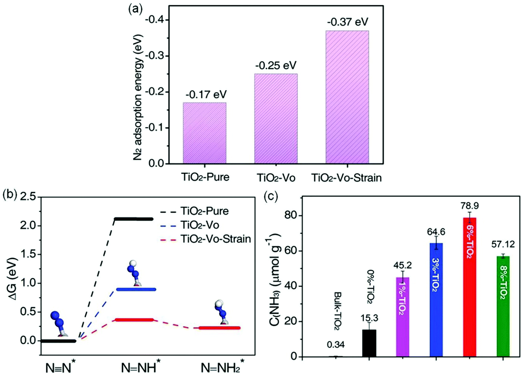 | ||
| Fig. 8 (a) The N2 adsorption energies by DFT calculations on different photocatalysts. (b) The calculated Gibbs free energy for N2 reduction on the (001) surface of different photocatalysts (H: white sphere, Ti: gray sphere, N: blue sphere, O: red sphere). (c) Yield of NH3 over various samples under UV-vis irradiation. Reproduced from ref. 68 with permission from Wiley-VCH. | ||
Apart from metal doping, a metal-free B-doped g-C3N4 nanosheet (BCN) with exposed active N atoms was recently synthesized for highly efficient ammonia synthesis.73 Theoretical studies revealed that the exposed N atoms could be stabilized by B–N–C coordination on BCN, which was different from that in the pristine g-C3N4. The B dopants were proved as active sites for N2 adsorption and activation and could effectively retard charge recombination and improve light utilization. The optimal BCN with 13.8 wt% B-dopants exhibited a remarkable NH3 yield rate of 313.9 μmol g−1 h−1 under visible light irradiation in the presence of Na2SO3 as a hole scavenger, which was much higher than that (32.8 μmol g−1 h−1) over pristine g-C3N4 and also achieved a good QE of around 0.64% at 420 nm. In addition, carbon-doped TiO2 was also reported for N2 photoreduction, which exhibited an NH3 yield rate of 109.3 μmol g−1 h−1.
Facets. Since the surface atomic distribution has a huge effect on the active sites and electronic structures of photocatalysts,69,74–76 many researchers attempted to control the crystal facet of semiconductors to enhance the photocatalytic N2 reduction. For instance, two Bi5O7I nanosheets with different {100} and {001} facets were synthesized successfully via hydrolysis and calcination methods, respectively.77 Further investigations revealed that Bi5O7I-001 had more negative conduction band position (−1.45 eV) compared with that in Bi5O7I-100 (−0.85 eV) and exhibited higher efficiency for separation of photoinduced carriers, thus leading to a high photocatalytic activity for N2 photoreduction. Accordingly, a remarkable NH3 generation rate of 111.5 μmol g−1 h−1 over Bi5O7I-001 was achieved using methanol as a hole scavenger and the AQE of that was increased to 5.1%.
In another report, Zhang et al. also systematically investigated the influence of {001} and {010} facets of OV-rich BiOCl nanosheets on N2 adsorption and activation.78 Experimental results showed that {010} facet BiOCl nanosheets (BOC-010) exhibited a superior performance with a NH3 yield of 4.62 μmol g−1 h−1, which was around 2.5 times higher than that on {001} facet BiOCl nanosheets (BOC-001, Fig. 9a). Meanwhile, it was observed that N2H4 which served as a main intermediate was accumulated on BOC-010 during N2 photoreduction reaction within 30 min and was consumed gradually to be converted into NH3 (Fig. 9b). Importantly, when N2H4 was used as the reactant, both BOC-010 and BOC-001 showed a similar photocatalytic conversion efficiency of N2H4 under simulated solar irradiation (Fig. 9c), which in turn meant that BOC-010 had a stronger ability to generate N2H4 intermediates. Further DFT calculations revealed that the N2 fixation on BOC-010 followed an alternative pathway with N2H4 as the main intermediate, which could provide a lower energy pathway for N2 fixation via proton-coupled electron transfer compared with that via a distal pathway occurring on BOC-001 facets, thus resulting in enhanced NH3 production (Fig. 9d and e).
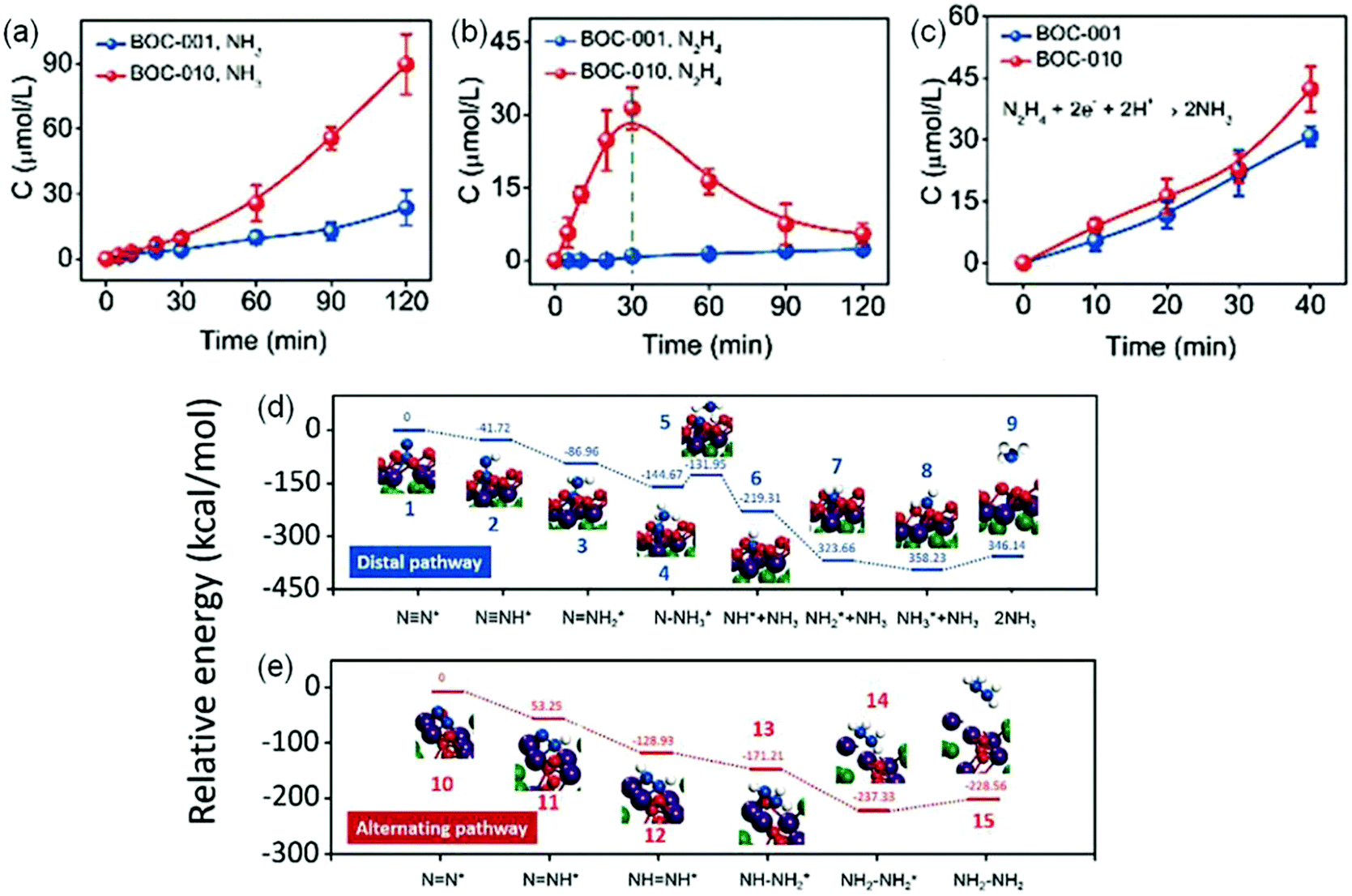 | ||
| Fig. 9 Photocatalytic performance for N2 reduction on BOC-001 and BOC-010. The yield comparison of produced (a) NH3 and (b) N2H4 on BOC-001 and BOC-010 under simulated solar light irradiation. (c) The NH3 yield produced from N2H4 BOC-001 and BOC-010 under simulated solar light irradiation. The calculated free energy change for N2 reduction (d) on the (001) surface via a distal pathway and (e) on the (010) surface via an alternating pathway. Reproduced from ref. 78 with permission from The Royal Society of Chemistry. | ||
Nanostructure engineering. Nanomaterials have preternatural interface structures and unique functions, such as the small size effect, the surface and boundary effect, quantum size and so on.79–85 In order to increase the catalytic active sites of the photocatalytic reduction of N2, Sun et al. synthesized BiO quantum dots with an average size of 2–5 nm (Fig. 10a), which showed an NH3 production rate of 1226 μmol g−1 h−1 without a cocatalyst and a sacrificial agent.86 Meanwhile, the amount of produced O2 increased continuously with increasing irradiation time, consistent with the stoichiometric chemistry. Kinetic analysis and quantum chemical calculations suggested that the highly efficient photocatalytic activity of BiO quantum dots could be attributed to the fact that the smaller size endowed the surface and edge of BiO rich in Bi2+ species, which had the potential to increase the electron donation to the anti-bonding π* orbitals of N2, thereby could act as active sites to adsorb and activate N2 (Fig. 10b). More recently, a tubular OV-rich Bi5O7Br (Bi5O7Br-NT) with a diameter of 5 nm (Fig. 10c) was prepared and it exhibited a maximum NH3 yield rate of 1.38 mmol g−1 h−1 (Fig. 10d) upon changing the OV concentration.87 A high specific surface area of up to 96.56 m2 g−1 was observed for Bi5O7Br-NT, which indicated the exposure of abundant surface OVs for the chemisorption and activation of N2. It was found that the OVs on the Bi5O7Br-NT surface could not only effectively promote N2 adsorption and activation, but also could be regenerated by capturing O atoms from H2O after the reaction to maintain the good stability of Bi5O7Br nanostructures. As a result, the calculated AQE for the Bi5O7Br-NT photocatalyst was 2.3% under visible light irradiation at 420 nm (Fig. 10e). Furthermore, it was reported that metal-free black phosphorus nanoflakes with abundant edges (eBP NFs) synthesized via a facile chemical etching exfoliation method exhibited a remarkable NH3 yield rate of 2.37 mmol g−1 h−1 under visible light irradiation in the presence of Na2SO3 and Na2S·9H2O as scavengers.88 The photoelectrochemical characteristics (PEC) and transient absorption (TA) studies revealed that the efficient ammonia synthesis was attributed to rich edges on the surface, which could provide abundant active sites for enhanced N2 adsorption and activation. Similarly, a nanocomposite (SiO2/C-RP) prepared by loading red phosphorus on SiO2 nanospheres showed superior charge separation.89 Besides, this hybrid nanostructure exhibited a large surface area, good water dispersibility and large light adsorption. As a result of these benefits, SiO2/C-RP exhibited an NH3 production yield of 0.73 μmol h−1 under full-spectrum irradiation.
 | ||
| Fig. 10 (a) TEM image of BiO quantum dots. (b) Proposed mechanism for N2 photoreduction on BiO quantum dots. Reproduced from ref. 86 with permission from The Royal Society of Chemistry. (c) TEM image of Bi5O7Br-NT. (d) Yield of NH3 for Bi5O7Br-NT. (e) The wavelength-dependent AQE of Bi5O7Br-NT. Reproduced from ref. 87 with permission from Wiley-VCH. | ||
Interfacial modulation
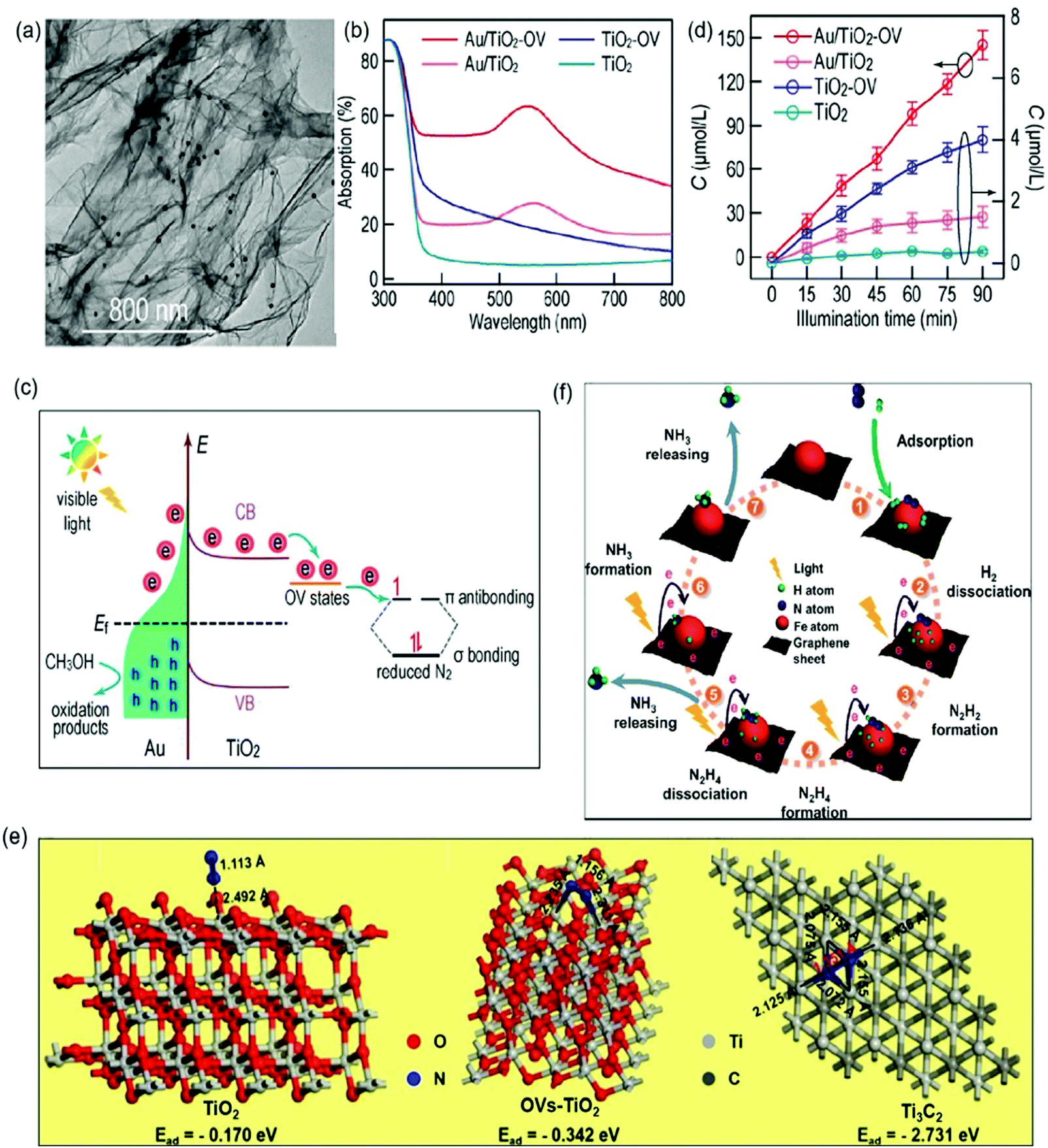 | ||
| Fig. 11 (a) TEM image of Au/TiO2-OV. (b) Adsorption spectra of different photocatalysts. (c) The proposed schematic for photocatalytic N2 reduction over the Au/TiO2-OV catalyst under visible-light irradiation. (d) Photocatalytic NH3 production with different photocatalysts under visible light irradiation. Reproduced from ref. 96 with permission from ACS Publication. (e) Schematic of the adsorption structure on TiO2 (A), OVs-TiO2 (B) and Ti3C2 MXenes (C). Reproduced from ref. 103 with permission from Elsevier Publication. (f) Schematic for photocatalytic N2 reduction over Fe@graphene photocatalysts. Reproduced from ref. 108 with permission from ACS Publication. | ||
In addition to TiO2-based photocatalysts, Pt-loaded ZnO was reported as an efficient photocatalyst for N2 photoreduction which exhibited an NH3 yield rate of 860 mmol g−1 h−1.104 More recently, O-doped 1T-MoS2 nanosheets with a large amount of SVs (SV-1T-MoS2) were used as cocatalysts over CdS nanorods for photocatalytic N2 reduction.105 The DFT calculations revealed that the SVs and the metal properties of 1T-MoS2 could effectively promote the separation of h+/e− and the presence of SV-1T-MoS2 could also provide abundant active sites, resulting in enhanced N2 adsorption and immobilization. Accordingly, a remarkable performance over the optimal SV-1T-MoS2/CdS was realized with a superior NH3 yield rate of 8220.83 μmol L−1 h−1 g−1 under simulated solar light irradiation. Besides, NiS was also studied as a cocatalyst over CdS nanorods for ammonia photosynthesis.106 The DFT calculation indicated that the NiS cocatalyst could reduce the adsorption energy of N2 from 1.16 eV on the CdS surface to −0.55 eV on the Ni-doped CdS surface. Further characterization revealed that charge separation could also be enhanced by loading NiS on the CdS surface. Because of these properties, a favorable NH3 yield of 2.8 mg L−1 was reported within the first hour in pure water under full-spectrum irradiation. Recently, single-atom Pt modified triazine framework (CTF) nanosheets (Pt-SACs/CTF) were developed for photocatalytic NH3 production.107 It was found that the Pt–N3 sites were formed in Pt-SACs/CTF, leading to more negative conduction band position with accelerated thermodynamics and fast interfacial charge migration ability, and therefore a high NH3 production rate of 171.4 μmol g−1 h−1 under visible light irradiation. Most recently, we synthesized a ternary Ru/RuO2/g-C3N4 system for N2 photoreduction, which exhibited a photocatalytic NH3 yield of 13.3 μmol g−1 h−1 whilst no NH3 could be measured for pure g-C3N4 under the same condition. Such significant improvement in photocatalytic NH3 synthesis for Ru/RuO2/g-C3N4 was not only because of Ru and RuO2 acting as cocatalysts to promote electron and hole transfer respectively, but also due to the advantage of Ru for N2 chemisorption and activation.108 Besides that, carbon-based materials especially graphene are also often used as cocatalysts to prevent the photoinduced electron–hole recombination and promote the electron transfer due to their prominent electrical conductivity.109,110 For instance, a Fe modified three-dimensional graphene (Fe@graphene) photocatalyst was reported for NH3 production.110 In the Fe@graphene system (Fig. 11f), graphene generated hot electrons under light irradiation and transferred those electrons to Fe, while Fe acted as an electron sink and provided the catalytic active sites for the adsorption and activation of N2.
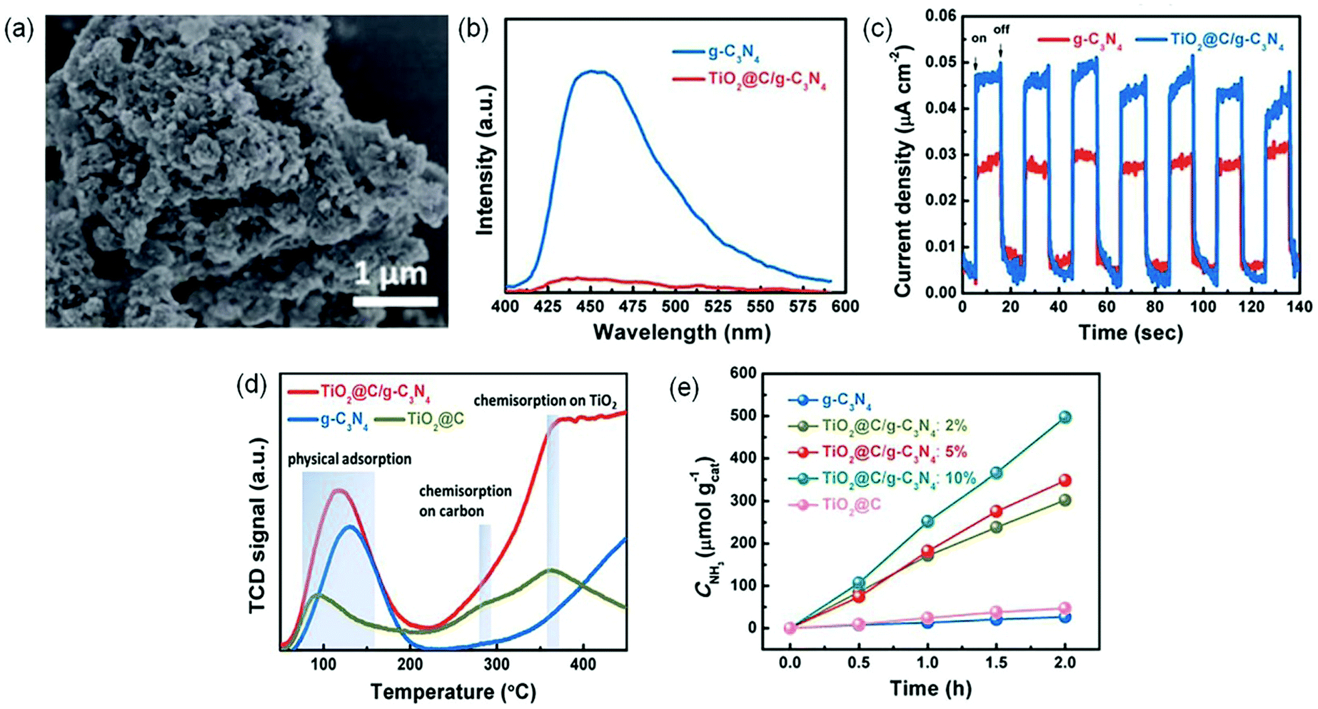 | ||
| Fig. 12 (a) SEM image of TiO2@C/g-C3N4. (b) PL spectra of TiO2@C/g-C3N4 and g-C3N4. (c) Transient photocurrent responses of TiO2@C/g-C3N4 and g-C3N4. (d) The N2-TPD profiles. (e) The yield of produced NH3 under visible light irradiation (λ > 420 nm). Reproduced from ref. 112 with permission from The Royal Society of Chemistry. | ||
Conclusion and perspectives
The photosynthesis of NH3 is an energy-saving process and has high potential for substantial contribution to economic and social sustainability. Compared with the traditional Haber–Bosch process and the emerging electrochemical process, photocatalytic NH3 synthesis exhibits very low efficiency, mostly at micromoles g−1 h−1 if using water as the electron donor, and thus is far from practical application. However as photocatalysis can be driven by abundant solar energy, it is a carbon-free process. Besides, it requires a solar energy input of 208.3 MJ kg−1-NH3 compared with that of 339.1 MJ kg−1-NH3 in the electrochemical process.117 Thus, it has strong potential to achieve NH3 synthesis with affordable costs in particular taking into account the sustainability and the trend of decarbonatization in the industry. However there is a long way to go in order to realize this potential.This review does not detail different photocatalysts as there are a few reviews on them, but analyses surface engineering and interface engineering in photocatalysts developed recently for the photocatalytic NH3 synthesis, involving oxygen vacancies, nitrogen vacancies, carbon vacancies, sulfur vacancies, metal and non-metal doping, facet modulation, nanostructure engineering, and heterostructure construction such as loading with cocatalysts and modification with other semiconductors, together with the mechanism of N2 reduction reaction and the reliable means for the detection of NH3.
Great progress has been made in the study of photoreduction of N2 to NH3 as briefed in Fig. 13, but there are still many problems, some of which are very critical. First, the majority of the studies so far reported use an efficient and expensive hole scavenger to get long lived photoelectrons for N2 reduction. However, a practical pathway should use water as the only electron donor and to provide protons for the photosynthesis of NH3, as such NH3 synthesis by photocatalysis is scientifically meaningful and economically sustainable. The slow progress linked to this profile is mainly due to the very limited understanding in this field. Second, there are few reports specifying the stoichiometric chemistry in the photochemical process. Without the stoichiometric O2 gas produced, such N2 reduction to NH3 is questionable. Furthermore, as O2 could be leaked from air, the isotopic measurement of O2 production is necessary. In addition, since H2 production would compete with NH3 synthesis, a comprehensive study should detail the selectivity between the two products and discuss the strategy to favor NH3 synthesis. In addition an experimental error bar is very crucial for such NH3 synthesis in order to improve the confidence as almost all studies were carried out in a batch reactor with quite a small amount of NH3 produced, which was quite easy to be interfered by occasional factors.
 | ||
| Fig. 13 Current work and future challenges highlighted in this review. | ||
Apart from the issues mentioned above, photocatalytic NH3 synthesis also faces a few tough challenges. The majority of the studies show that the NH4 amount produced is less than 10 μmol h−1 (instead of the unit of μmol g−1 h−1) when using water as the electron donor and 10 times enhancement is achieved when using an organic hole scavenger. This amount is lower than the NH3 amount in the river water which is about 0.01 mM.118 Besides, since the NH3 yield is extremely easy to be interfered by environmental impurities and different detection agents, it is difficult to obtain reliable and reproducible results by just one analysis method.119 At least two methods have to be applied to prove the consistent results and to improve the reproducibility of the process.
The surface states of a catalyst can dominate its performance, such as surface defects. However, to quantify the correlation of the surface defects with the catalytic activity is very challenging at present. This should be undertaken in the future in order to distinctly guide catalyst surface state control. Furthermore the cocatalyst is another key factor to control both charge separation and catalytic performance. The majority of the cocatalysts reported are either large particles or nanosized particles. Single atomic catalysis is an emerging area, which presents unprecedented activity in some chemical processes. Such unique reaction sites should be introduced to ammonia synthesis with in-depth exploration of their intrinsic function. In addition, a junction structure is widely accepted to help charge separation, which was also reviewed in the previous session. The new design strategy should be applied to construct new junctions, such as polymer and oxide junctions as the former has likely better N2 adsorption due to the potential hydrogen bond between the organic polymer and N2 while the latter has a very positive VB for water oxidation.
The modified catalyst discovery is very informative. Equally, the mechanism and reaction pathways for photocatalytic N2 fixation are scarce and much less investigated, forming an obstacle for the rational design of highly efficient photocatalysts. Currently, most of the given reaction mechanisms and reaction pathways were based on assumptions and lacked solid evidence. Thus, the current catalyst development is more or less a try-and-error process. Some advanced operando technologies in functional characterization should be applied to comprehensively study the reaction pathway such as by time resolved spectroscopy to investigate charge carrier dynamics, and by transient and stationary spectroscopy to observe the reaction intermediates.
In addition, it is of paramount importance to design a flow reaction system for N2 photoreduction. The current reaction system is composed of a batch reactor, which is far from the requirement of the industry. The typical batch reactor is easy to be constructed; however, its efficiency is severely restricted by the low mass transfer between N2 gas and aqueous solution due to the low solubility of N2, thereby resulting in a low photocatalytic efficiency. Besides, NH3 accumulated in the batch reactor during the reaction process will be overoxidized to other byproducts, thereby resulting in a low conversion rate and even bad selectivity. Moreover, based on the industrial viewpoint, it is quite costly to separate the photocatalysts from reactants and products in a batch system. Thus, an intensified flow reactor such as using N2 and water vapor as reactants should be explored to overcome these drawbacks and to meet the industrial requirement in the future, underlining the crucial collaborations between chemical scientists and experts in reaction engineering.
Last, modelling will be expected to combine with experimental results to figure out the reaction mechanism and speed up the rational design of highly efficient photocatalysts. Meanwhile, the big data, together with artificial intelligence (AI) and machine learning (ML), will be a future key research area to improve the reproducibility of the catalyst synthesis, to facilitate catalyst screening, to enhance the experimental safety and to save the experimental costs and time.
Overall, this research field is at an infant state and all these areas should be enhanced in order to improve the NH3 synthesis rate with high reproducibility and reliability of the procedure.
Conflicts of interest
There are no conflicts to declare.Acknowledgements
Q. H. is thankful for the NSFC grants (21575014 and 21905025), Beijing Natural Science Foundation (2184122), the Fundamental Research Funds for the Central Universities (2018CX01017), Beijing Institute of Technology Research Fund Program for Young Scholars, and Analysis & Testing Center at Beijing Institute of Technology. H.M.J is thankful for the UCL Dean's prize and China CSC scholarship. All authors are thankful for financial support from UK EPSRC (EP/N009533/1), Royal Society-Newton Advanced Fellowship Grant (NA170422) and the Leverhulme Trust (RPG-2017-122).References
- V. Smil, Nature, 1999, 400, 415 CrossRef CAS.
- H. P. Jia and E. A. Quadrelli, Chem. Soc. Rev., 2014, 43, 547–564 RSC.
- K. Ithisuphalap, H. Zhang, L. Guo, Q. Yang, H. Yang and G. Wu, Small Methods, 2019, 3, 1800352 CrossRef.
- G. Ertl, Angew. Chem., Int. Ed., 2008, 47, 3524–3535 CrossRef CAS.
- R. Schlögl, Angew. Chem., Int. Ed., 2003, 42, 2004–2008 CrossRef.
- C. Mao, J. Wang, Y. Zou, H. Li, G. Zhan, J. Li, J. Zhao and L. Zhang, Green Chem., 2019, 21, 2852–2867 RSC.
- P. Wang, F. Chang, W. Gao, J. Guo, G. Wu, T. He and P. Chen, Nat. Chem., 2017, 9, 64–70 CrossRef CAS.
- N. Cherkasov, A. O. Ibhadon and P. Fitzpatrick, Chem. Eng. Process., 2015, 90, 24–33 CrossRef CAS.
- G. Duan, Y. Chen, Y. Tang, K. A. M. Gasem, P. Wan, D. Ding and M. Fan, Prog. Energy Combust. Sci., 2020, 81, 100860 CrossRef.
- R. Zhao, H. Xie, L. Chang, X. Zhang, X. Zhu, X. Tong, T. Wang, Y. Luo, P. Wei, Z. Wang and X. Sun, EnergyChem, 2019, 1, 100011 CrossRef.
- S. C. Sun, X. Y. Zhang, X. L. Liu, L. Pan, X. W. Zhang and J. J. Zou, Acta Phys.-Chim. Sin., 2020, 36, 1905007 Search PubMed.
- Y. Zhao, R. Shi, X. Bian, C. Zhou, Y. Zhao, S. Zhang, F. Wu, G. I. N. Waterhouse, L. Z. Wu, C. H. Tung and T. Zhang, Adv. Sci., 2019, 6, 1802109 CrossRef.
- Y. Huang, N. Zhang, Z. Wu and X. Xie, J. Mater. Chem. A, 2020, 8, 4978–4995 RSC.
- A. J. Medford and M. C. Hatzell, ACS Catal., 2017, 7, 2624–2643 CrossRef CAS.
- C. Guo, J. Ran, A. Vasileff and S. Z. Qiao, Energy Environ. Sci., 2018, 11, 45–56 RSC.
- Y. J. Zhang, F. X. Mao, L. J. Wang, H. Y. Yuan, P. F. Liu and H. G. Yang, Sol. RRL, 2020, 4, 1900438 CrossRef CAS.
- G. N. Schrauzer and T. D. Guth, J. Am. Chem. Soc., 1977, 99, 7189–7193 CrossRef CAS.
- M. Cheng, C. Xiao and Y. Xie, J. Mater. Chem. A, 2019, 7, 19616–19633 RSC.
- D. Yan, H. Li, C. Chen, Y. Zou and S. Wang, Small Methods, 2019, 3, 1800331 CrossRef.
- S. Zhang, Y. Zhao, R. Shi, C. Zhou, G. I. N. Waterhouse, L. Z. Wu, C. H. Tung and T. Zhang, Adv. Energy Mater., 2020, 10, 1901973 CrossRef CAS.
- Y. Zhao, R. Shi, X. Bian, C. Zhou, Y. Zhao, S. Zhang, F. Wu, G. I. N. Waterhouse, L. Z. Wu, C. H. Tung and T. Zhang, Adv. Sci., 2019, 6, 1802109 CrossRef.
- X. Chen, N. Li, Z. Kong, W. J. Ong and X. Zhao, Mater. Horiz., 2018, 5, 9–27 RSC.
- X. Xue, R. Chen, H. Chen, Y. Hu, Q. Ding, Z. Liu, L. Ma, G. Zhu, W. Zhang, Q. Yu, J. Liu, J. Ma and Z. Jin, Nano Lett., 2018, 18, 7372–7377 CrossRef CAS.
- X. Y. Xie, P. Xiao, W.-H. Fang, G. Cui and W. Thiel, ACS Catal., 2019, 9, 9178–9187 CrossRef CAS.
- A. J. Medford and M. C. Hatzell, ACS Catal., 2017, 7, 2624–2643 CrossRef CAS.
- J. Li, H. Li, G. Zhan and L. Zhang, Acc. Chem. Res., 2017, 50, 112–121 CrossRef CAS.
- M. A. Shipman and M. D. Symes, Catal. Today, 2017, 286, 57–68 CrossRef CAS.
- C. Ling, Y. Zhang, Q. Li, X. Bai, L. Shi and J. Wang, J. Am. Chem. Soc., 2019, 141, 18264–18270 CrossRef CAS.
- X. Gao, Y. Wen, D. Qu, L. An, S. Luan, W. Jiang, X. Zong, X. Liu and Z. Sun, ACS Sustainable Chem. Eng., 2018, 6, 5342–5348 CrossRef CAS.
- A. Banerjee, B. D. Yuhas, E. A. Margulies, Y. Zhang, Y. Shim, M. R. Wasielewski and M. G. Kanatzidis, J. Am. Chem. Soc., 2015, 137, 2030–2034 CrossRef CAS.
- H. Li, J. Shang, Z. Ai and L. Zhang, J. Am. Chem. Soc., 2015, 137, 6393–6399 CrossRef CAS.
- H. Hirakawa, M. Hashimoto, Y. Shiraishi and T. Hirai, J. Am. Chem. Soc., 2017, 139, 10929–10936 CrossRef CAS.
- C. Li, T. Wang, Z. J. Zhao, W. Yang, J.-F. Li, A. Li, Z. Yang, G. A. Ozin and J. Gong, Angew. Chem., Int. Ed., 2018, 57, 5278–5282 CrossRef CAS.
- Y. Zhao, X. Jia, G. I. N. Waterhouse, L.-Z. Wu, C. H. Tung, D. O'Hare and T. Zhang, Adv. Energy Mater., 2016, 6, 1501974 CrossRef.
- S. Zhang, Y. Zhao, R. Shi, C. Zhou, G. I. N. Waterhouse, L. Z. Wu, C. H. Tung and T. Zhang, Adv. Energy Mater., 2020, 10, 1901973 CrossRef CAS.
- Y. Zhao, Y. Zhao, G. I. N. Waterhouse, L. Zheng, X. Cao, F. Teng, L. Z. Wu, C. H. Tung, D. O'Hare and T. Zhang, Adv. Mater., 2017, 29, 1703828 CrossRef.
- L. Ye, L. Zan, L. Tian, T. Peng and J. Zhang, Chem. Commun., 2011, 47, 6951–6953 RSC.
- H. Li and L. Zhang, Nanoscale, 2014, 6, 7805–7810 RSC.
- J. Chen, T. Ding, J. Cai, Y. Wang, M. Wu, H. Zhang, W. Zhao, Y. Tian, X. Wang and X. Li, Appl. Surf. Sci., 2018, 453, 101–109 CrossRef CAS.
- Y. Wang, J. Cai, M. Wu, J. Chen, W. Zhao, Y. Tian, T. Ding, J. Zhang, Z. Jiang and X. Li, Appl. Catal., B, 2018, 239, 398–407 CrossRef CAS.
- Y. Huang, Y. Yu, Y. Yu and B. Zhang, Sol. RRL, 2020, 4, 2000037 CrossRef CAS.
- Q. Han, B. Wang, J. Gao, Z. Cheng, Y. Zhao, Z. Zhang and L. Qu, ACS Nano, 2016, 10, 2745–2751 CrossRef CAS.
- Q. Han, Z. Cheng, B. Wang, H. Zhang and L. Qu, ACS Nano, 2018, 12, 5221–5227 CrossRef CAS.
- H. Ou, L. Lin, Y. Zheng, P. Yang, Y. Fang and X. Wang, Adv. Mater., 2017, 29, 1700008 CrossRef.
- Q. Han, B. Wang, J. Gao and L. Qu, Angew. Chem., Int. Ed., 2016, 55, 10849–10853 CrossRef CAS.
- Q. Han, B. Wang, Y. Zhao, C. Hu and L. Qu, Angew. Chem., Int. Ed., 2015, 54, 11433–11437 CrossRef CAS.
- Y. Liang, F. Liu, Y. Deng, Q. Zhou, Z. Cheng, P. Zhang, Y. Xiao, L. Lv, H. Liang, Q. Han, H. Shao and L. Qu, Small, 2018, 14, 1801916 CrossRef.
- Q. Han, C. Hu, F. Zhao, Z. Zhang, N. Chen and L. Qu, J. Mater. Chem. A, 2015, 3, 4612–4619 RSC.
- L. Chen, Y. Wang, C. Wu, G. Yu, Y. Yin, C. Su, J. Xie, Q. Han and L. Qu, Nanoscale, 2020, 12, 13484–13490 RSC.
- Q. Han, N. Chen, J. Zhang and L. Qu, Mater. Horiz., 2017, 4, 832–850 RSC.
- B. He, M. Feng, X. Chen and J. Sun, Green Energy Environ., 2020 DOI:10.1016/j.gee.2020.07.011.
- Y. Wang and S. Shen, Acta Phys.-Chim. Sin., 2020, 36, 1905080 Search PubMed.
- W. J. Ong, L. K. Putri and A. R. Mohamed, Chem. – Eur. J., 2020, 26, 9710–9748 CrossRef CAS.
- G. Dong, W. Ho and C. Wang, J. Mater. Chem. A, 2015, 3, 23435–23441 RSC.
- W. Wang, H. Zhang, S. Zhang, Y. Liu, G. Wang, C. Sun and H. Zhao, Angew. Chem., Int. Ed., 2019, 11, 16644–16650 CrossRef.
- S. Cao, B. Fan, Y. Feng, H. Chen, F. Jiang and X. Wang, Chem. Eng. J., 2018, 353, 147–156 CrossRef CAS.
- Y. Cao, S. Hu, F. Li, Z. Fan, J. Bai, G. Lu and Q. Wang, RSC Adv., 2016, 6, 49862–49867 RSC.
- V. Kumaravel, S. Mathew, J. Bartlett and S. C. Pillai, Appl. Catal., B, 2019, 244, 1021–1064 CrossRef CAS.
- Z. Shayegan, C. S. Lee and F. Haghighat, Chem. Eng. J., 2018, 334, 2408–2439 CrossRef CAS.
- J. J. Carey and M. Nolan, J. Mater. Chem. A, 2017, 5, 15613–15630 RSC.
- Y. Shi, Y. Zhou, D. R. Yang, W. X. Xu, C. Wang, F. B. Wang, J. J. Xu, X.-H. Xia and H. Y. Chen, J. Am. Chem. Soc., 2017, 139, 15479–15485 CrossRef CAS.
- E. Paek, A. J. Pak and G. S. Hwang, ACS Appl. Mater. Interfaces, 2014, 6, 12168–12176 CrossRef CAS.
- J. Zhang, Y. Liu, C. Sun, P. Xi, S. Peng, D. Gao and D. Xue, ACS Energy Lett., 2018, 3, 779–786 CrossRef CAS.
- W. Zhao, J. Zhang, X. Zhu, M. Zhang, J. Tang, M. Tan and Y. Wang, Appl. Catal., B, 2014, 144, 468–477 CrossRef CAS.
- J. Luo, X. Bai, Q. Li, X. Yu, C. Li, Z. Wang, W. Wu, Y. Liang, Z. Zhao and H. Liu, Nano Energy, 2019, 66, 104187 CrossRef CAS.
- N. Zhang, L. Li, Q. Shao, T. Zhu, X. Huang and X. Xiao, ACS Appl. Energy Mater., 2019, 2, 8394–8398 CrossRef CAS.
- N. Zhang, A. Jalil, D. Wu, S. Chen, Y. Liu, C. Gao, W. Ye, Z. Qi, H. Ju, C. Wang, X. Wu, L. Song, J. Zhu and Y. Xiong, J. Am. Chem. Soc., 2018, 140, 9434–9443 CrossRef CAS.
- Y. Zhao, Y. Zhao, R. Shi, B. Wang, G. I. N. Waterhouse, L. Z. Wu, C. H. Tung and T. Zhang, Adv. Mater., 2019, 31, 1806482 CrossRef.
- Y. Bi, S. Ouyang, N. Umezawa, J. Cao and J. Ye, J. Am. Chem. Soc., 2011, 133, 6490–6492 CrossRef CAS.
- P. V. Kamat, Acc. Chem. Res., 2017, 50, 527–531 CrossRef CAS.
- Q. Hao, C. Liu, G. Jia, Y. Wang, H. Arandiyan, W. Wei and B. J. Ni, Mater. Horiz., 2020, 7, 1014–1029 RSC.
- Z. Li, Z. Gao, B. Li, L. Zhang, R. Fu, Y. Li, X. Mu and L. Li, Appl. Catal., B, 2020, 262, 118276 CrossRef CAS.
- W. Wang, H. Zhou, Y. Liu, S. Zhang, Y. Zhang, G. Wang, H. Zhang and H. Zhao, Small, 2020, 16, 1906880 CrossRef CAS.
- M. Setvin, X. Hao, B. Daniel, J. Pavelec, Z. Novotny, G. S. Parkinson, M. Schmid, G. Kresse, C. Franchini and U. Diebold, Angew. Chem., Int. Ed., 2014, 53, 4714–4716 CrossRef CAS.
- J. Bai, B. Lu, Q. Han, Q. Li and L. Qu, ACS Appl. Mater. Interfaces, 2018, 10, 38066–38072 CrossRef CAS.
- G. Liu, J. C. Yu, G. Q. Lu and H. M. Cheng, Chem. Commun., 2011, 47, 6763–6783 RSC.
- Y. Bai, L. Ye, T. Chen, L. Wang, X. Shi, X. Zhang and D. Chen, ACS Appl. Mater. Interfaces, 2016, 8, 27661–27668 CrossRef CAS.
- H. Li, J. Shang, J. Shi, K. Zhao and L. Zhang, Nanoscale, 2016, 8, 1986–1993 RSC.
- Q. Han, Z. Cheng, J. Gao, Y. Zhao, Z. Zhang, L. Dai and L. Qu, Adv. Funct. Mater., 2017, 27, 1606352 CrossRef.
- Y. O. Wang, F. Silveri, M. K. Bayazit, Q. S. Ruan, Y. M. Li, J. J. Xie, C. R. A. Catlow and J. W. Tang, Adv. Energy Mater., 2018, 8, 1801084 CrossRef.
- Q. Han, F. Zhao, C. Hu, L. Lv, Z. Zhang, N. Chen and L. Qu, Nano Res., 2015, 8, 1718–1728 CrossRef CAS.
- J. Bai, Q. Han, Z. Cheng and L. Qu, Chem. – Asian J., 2018, 13, 3160–3164 CrossRef CAS.
- L. W. Chen, X. T. Ding, J. F. Zeng, C. B. Wu, Q. Han and L. T. Qu, Sci. Bull., 2019, 54, 718–722 CrossRef.
- Y. Wang, R. Xu, L. Chen, C. Wu, L. Qiu, C. D. Windle, Q. Han and L. Qu, ACS Appl. Mater. Interfaces, 2020, 12, 8547–8554 CrossRef CAS.
- G. Zhang, C. D. Sewell, P. Zhang, H. Mi and Z. Lin, Nano Energy, 2020, 71, 104645 CrossRef CAS.
- S. Sun, Q. An, W. Wang, L. Zhang, J. Liu and W. A. Goddard III, J. Mater. Chem. A, 2017, 5, 201–209 RSC.
- S. Wang, X. Hai, X. Ding, K. Chang, Y. Xiang, X. Meng, Z. Yang, H. Chen and J. Ye, Adv. Mater., 2017, 29, 1701774 CrossRef.
- S. Bian, M. Wen, J. Wang, N. Yang, P. K. Chu and X. F. Yu, J. Phys. Chem. Lett., 2020, 11, 1052–1058 CrossRef CAS.
- L. Lin, Q. Zhu, A. Cheng and L. Ma, Catal. Sci. Technol., 2020, 10, 4119–4125 RSC.
- J. Ran, J. Zhang, J. Yu, M. Jaroniec and S. Z. Qiao, Chem. Soc. Rev., 2014, 43, 7787–7812 RSC.
- R. Li, H. Han, F. Zhang, D. Wang and C. Li, Energy Environ. Sci., 2014, 7, 1369–1376 RSC.
- G. Zhang, Z. A. Lan and X. Wang, Chem. Sci., 2017, 8, 5261–5274 RSC.
- K. T. Ranjit, T. K. Varadarajan and B. Viswanathan, J. Photochem. Photobiol., A, 1996, 96, 181–185 CrossRef CAS.
- Q. Zhang and J. Guan, Sol. RRL, 2020, 4, 2000283 CrossRef CAS.
- S. Liu, Y. Wang, S. Wang, M. You, S. Hong, T. S. Wu, Y. L. Soo, Z. Zhao, G. Jiang, Q. Jieshan, B. Wang and Z. Sun, ACS Sustainable Chem. Eng., 2019, 7, 6813–6820 CrossRef CAS.
- J. Yang, Y. Guo, R. Jiang, F. Qin, H. Zhang, W. Lu, J. Wang and J. C. Yu, J. Am. Chem. Soc., 2018, 140, 8497–8508 CrossRef CAS.
- R. Wang, T. Xie, Z. Sun, T. Pu, W. Li and J.-P. Ao, RSC Adv., 2017, 7, 51687–51694 RSC.
- X. W. Guo, S. M. Chen, H. J. Wang, Z. M. Zhang, H. Lin, L. Song and T. B. Lu, J. Mater. Chem. A, 2019, 7, 19831–19837 RSC.
- S. Chang and X. Xu, Inorg. Chem. Front., 2020, 7, 620–624 RSC.
- J. Wang, C. Hua, X. Dong, Y. Wang and N. Zheng, Sustainable Energy Fuels, 2020, 4, 1855–1862 RSC.
- J. J. Xie, R. Jin, A. Li, Q. Ruan, Y. Deng, Y. Zhang, S. Yao, G. Sankar, D. Ma and J. W. Tang, Nat. Catal., 2018, 11, 889–896 CrossRef.
- J. Yang, D. Wang, H. Han and C. Li, Acc. Chem. Res., 2013, 46, 1900–1909 CrossRef CAS.
- Y. Liao, J. Qian, G. Xie, Q. Han, W. Dang, Y. Wang, L. Lv, S. Zhao, L. Luo, W. Zhang, H.-Y. Jiang and J. Tang, Appl. Catal., B, 2020, 273, 119054 CrossRef CAS.
- C. M. Janet, S. Navaladian, B. Viswanathan, T. K. Varadarajan and R. P. Viswanath, J. Phys. Chem. C, 2010, 114, 2622–2632 CrossRef CAS.
- B. Sun, Z. Liang, Y. Qian, X. Xu, Y. Han and J. Tian, ACS Appl. Mater. Interfaces, 2020, 12, 7257–7269 CrossRef CAS.
- X. Gao, L. An, D. Qu, W. Jiang, Y. Chai, S. Sun, X. Liu and Z. Sun, Sci. Bull., 2019, 64, 918–925 CrossRef CAS.
- J. Li, P. Liu, Y. Tang, H. Huang, H. Cui, D. Mei and C. Zhong, ACS Catal., 2020, 10, 2431–2442 CrossRef CAS.
- H. Wang, X. Li, Q. Ruan and J. Tang, Nanoscale, 2020, 12, 12329–12335 RSC.
- S. X. Wang, H. Maimaiti, B. Xu, Y. Guo, P. S. Zhai and H. Z. Zhang, J. Phys. Chem. C, 2019, 123, 31119–31129 CrossRef CAS.
- Y. Lu, Y. Yang, T. Zhang, Z. Ge, H. Chang, P. Xiao, Y. Xie, L. Hua, Q. Li, H. Li, B. Ma, N. Guan, Y. Ma and Y. Chen, ACS Nano, 2016, 10, 10507–10515 CrossRef CAS.
- E. Vesali-Kermani, A. Habibi-Yangjeh, H. Diarmand-Khalilabad and S. Ghosh, J. Colloid Interface Sci., 2020, 563, 81–91 CrossRef CAS.
- Q. Liu, L. Ai and J. Jiang, J. Mater. Chem. A, 2018, 6, 4102–4110 RSC.
- H. Mou, J. Wang, D. Zhang, D. Yu, W. Chen, D. Wang and T. Mu, J. Mater. Chem. A, 2019, 7, 5719–5725 RSC.
- W. J. Ong and K. P. Y. Shak, Sol. RRL, 2020, 4, 2000132 CrossRef CAS.
- W. Zhang, A. R. Mohamed and W. J. Ong, Angew. Chem., Int. Ed., 2020 DOI:10.1002/anie.201914925.
- X. Xue, R. Chen, C. Yan, Y. Hu, W. Zhang, S. Yang, L. Ma, G. Zhu and Z. Jin, Nanoscale, 2019, 11, 10439–10445 RSC.
- L. Wang, M. Xia, H. Wang, K. Huang, C. Qian, C. T. Maravelias and G. A. Ozin, Joule, 2018, 2, 1055–1074 CrossRef CAS.
- S. Gandaseca, N. Rosli, J. Ngayop and C. Arianto, Am. J. Environ. Sci., 2011, 7, 269–275 CrossRef CAS.
- S. Z. Andersen, V. Čolić, S. Yang, J. A. Schwalbe, A. C. Nielander, J. M. McEnaney, K. Enemark-Rasmussen, J. G. Baker, A. R. Singh, B. A. Rohr, M. J. Statt, S. J. Blair, S. Mezzavilla, J. Kibsgaard, P. C. K. Vesborg, M. Cargnello, S. F. Bent, T. F. Jaramillo, I. E. L. Stephens, J. K. Nørskov and I. Chorkendorff, Nature, 2019, 570, 504–508 CrossRef CAS.
Footnote |
| † Co-first authors: These authors contributed equally to this work. |
| This journal is © The Royal Society of Chemistry 2021 |