
 Open Access Article
 This Open Access Article is licensed under a Creative Commons Attribution-Non Commercial 3.0 Unported Licence
Microbial factories: monitoring vitamin B2 production by Escherichia coli in microfluidic cultivation chambers†
Petra
Jusková
 a,
Steven
Schmitt
b,
Lucas
Armbrecht
a and
Petra S.
Dittrich
*a
a,
Steven
Schmitt
b,
Lucas
Armbrecht
a and
Petra S.
Dittrich
*a
aDepartment of Biosystems Science and Engineering, Bioanalytics Group, ETH Zürich, Mattenstrasse 26, CH-4058 Basel, Switzerland. E-mail: petra.dittrich@bsse.ethz.ch
bDepartment of Biosystems Science and Engineering, Bioprocess Laboratory, ETH Zürich, Mattenstrasse 26, CH-4058 Basel, Switzerland
First published on 25th September 2021
Abstract
Microbial cells represent a standard production host for various important biotechnological products. Production yields can be increased by optimising strains and growth conditions and understanding deviations in production rates over time or within the microbial population. We introduce here microfluidic cultivation chambers for highly parallel studies on microbial cultures, enabling continuous biosynthesis monitoring of the industrially relevant product by Escherichia coli cells. The growth chambers are defined by ring-valves that encapsulate a volume of 200 pL when activated. Bacterial cells, labelled with magnetic beads, are inoculated in a small magnetic trap, positioned in the centre of each chamber. Afterwards, the ring-valves are partially activated, allowing for exchange reagents, such as the addition of fresh media or specific inducers of biosynthesis, while the bacterial cells and their progeny are maintained inside. On this platform, we monitor the production of riboflavin (vitamin B2). We used different variants of a riboflavin-overproducing bacterial strain with different riboflavin production levels and could distinguish them on the level of individual micro-colonies. In addition, we could also observe differences in the bacterial morphology with respect to the production. The presented platform represents a flexible microfluidic tool for further studies of microbial cell factories.
Introduction
Microbial cell factories represent a sustainable alternative to many chemical processes employed for the production of structurally complex compounds by the pharmaceutical and chemical industry.1 Secretion levels of the selected microbial metabolites can be elevated by rational design2 or directed evolution.3,4 However, the production yields in large-scale fermenters still vary over time, even for the optimized microbial producers.5 Genetic drift in the culture due to plasmid instability together with the inhomogeneous distribution of metabolites or proteins could, over several generations, lead to the formation of the sub-populations with significant differences in the production rates.6–8 The cells with low metabolic burden resulting from the decreased production typically manifest with increased growth rates, outcompeting the high producers and negatively affecting overall process performance. Therefore, monitoring the microbial production on the scale of one to several cells would provide important information regarding the batch heterogeneity and the presence of apparent outliers with significant difference in production yield.The standard tools for batch studies of bacterial cells, including microtitration well-plates and test tubes, do not provide detailed information on cell sub-populations and morphology. This was partially addressed by integration of microfluidic systems into the microbiology toolset.9,10 In particular, gel beads11,12 alongside single- and double-emulsions, have been applied for directed evolution13–15 and compound screening16 on a single-cell resolution.17 Droplet microfluidics enables high-throughput production with excellent homogeneity,18 however, continuous medium exchange, addition of reagents and product accumulation remain challenging.19 Recently introduced cultivation platforms based on semi-permeable shells20 or artificial phospholipid membranes21 allow for isolation of the cultivated cells with a partial access to the cultivation compartments. In these approaches, the selection of the molecules which can be retained or supplied to the compartments is highly restricted by the properties of the used materials (i.e. gels, polymers, lipids), and need to be adjusted for the particular application.
In contrast to droplets, platforms with small cultivation chambers allow for continuous nutrient or analyte supply to the cultivated cells with the possibility to monitor microbial production or response to the external stimuli.22,23 Chamber systems typically include a micro-sieve,24 particle membrane25 or specifically designed channel-restricting structures26–29 in order to maintain bacterial cells in the particular cultivation sites. These previous platforms have demonstrated the great potential of miniaturization for cultivation and observation of microbial populations, however, as the cultivation chambers are not separated, they cannot be employed for the accumulation and monitoring of secreted compounds.
In this paper, we present a microfluidic platform which allows for the cultivation of bacterial cells as small micro-cultures and monitoring of their secreted products. The micro-chambers are formed by ring-shaped valves, where in contrast to previous studies30 the inoculation is achieved by a magnetic trapping system.31 In addition, here we make use of the possibility to fully close or open the valves, or to provide a tiny opening by the precise adjustment of applied pressure, allowing nutrients to enter while cells are retained in the chamber. The system is optimized to perform dynamic studies of riboflavin (vitamin B2) producing recombinant Escherichia coli, where we detail the production performance of variants on a single micro-culture resolution. The influence of the inducer of the gene cluster responsible for the riboflavin production as well as riboflavin production under antibiotic pressure were evaluated. At the same time, we monitored cell morphology during the cultivation period.
Results and discussion
The microfluidic cultivation platform is composed of an array of about 600 individual, pL-sized circular cultivation chambers (Fig. 1A and S1†). The platform contains two channel networks separated by a thin layer of poly(dimethylsiloxane)(PDMS). The top channel network functions as a valve system, which by pressure actuation results in formation of growth chambers inside the ring-shaped valves (Fig. 1B). The bottom channel network contains the inlet and outlet for the inoculation of the growth chambers and liquid exchange during the cultivation period. Bacterial cells are first cultivated off-chip until they reach an OD600 in the range of 0.4–0.6 and labelled with magnetic beads functionalized by bacteria-specific antibodies incubating for 30–60 minutes with the suspension of magnetic beads. Magnetically labelled bacterial culture is introduced in the microfluidic device using a flow rate of 0.7 μL min−1. | ||
| Fig. 1 A: The microfluidic device with an array of about 600 growth chambers, composed of two channel networks: the top part contains pressure actuated microfluidic valves (red) and the bottom part contains inlet and outlet for the bacteria and reagent supply (blue). Scale bar: 5 mm. B: Micrograph with a detail view of the device with microfluidic valves, with and without the applied pressure. The pressure actuated valve surrounding the cell trap forms an isolated growth chamber. Scale bar: 75 μm C: Scheme of one microfluidic cultivation chamber and experimental workflow. E. coli bound to magnetic beads are captured by the magnetic force in the cell trap, designed as an indentation in the central part of the microchamber (1). Afterwards, the ring valves are activated and the magnet is removed (2). The remaining tiny gap between valve and bottom glass slide can be controlled by the applied pressure and allows us to access bacterial cells at different time points, i.e. addition of inducer, antibiotic or nutrients without loss of cells. The system described here is used to monitor riboflavin-secreting cells which also produce red fluorescent protein (mKate2) to provide information regarding the bacterial biomass. | ||
The in-house-made holder for the microfluidic device allows for placing a magnet at the area above the microfluidic traps (Fig. S1†). In the presence of a magnetic field, bacteria are drawn into the cell trap, i.e., an indentation in the centre of each chamber (Fig. 1C). In approximately 10 minutes, we typically observe that around 70% of the traps are inoculated. The occupancy of 1–5 cells in 90% of the traps is sufficient to form micro-culture and compare the biosynthesis between the chambers. (Table S1 and Fig. S2†). The growth chambers of approximately 200 pL are formed by the application of air pressure (2.2 bar) on the microfluidic valves. The chambers are not completely sealed, the narrow gap between the valves and glass slide allows for nutrient exchange over the cultivation period while the cells and their progeny remain trapped within the growth chambers. The applied pressure of 2.2 bar and the flow rate of 0.2 μL min−1 allow the solution inside the chamber to be completely exchanged in roughly four hours (Fig. S3†). Therefore, the cell-secreted compounds are partially removed from the chambers, while the remaining product still provides the information about the production dynamics.
The performance of the proposed cultivation platform is characterized using the Escherichia coli strain BW23474 [pB2-ribDBECA-mkate2] (Fig. 2A), which produces the industrially relevant compound riboflavin (vitamin B2) under the control of the tetracycline inducible tetR/tetO promoter.32,33
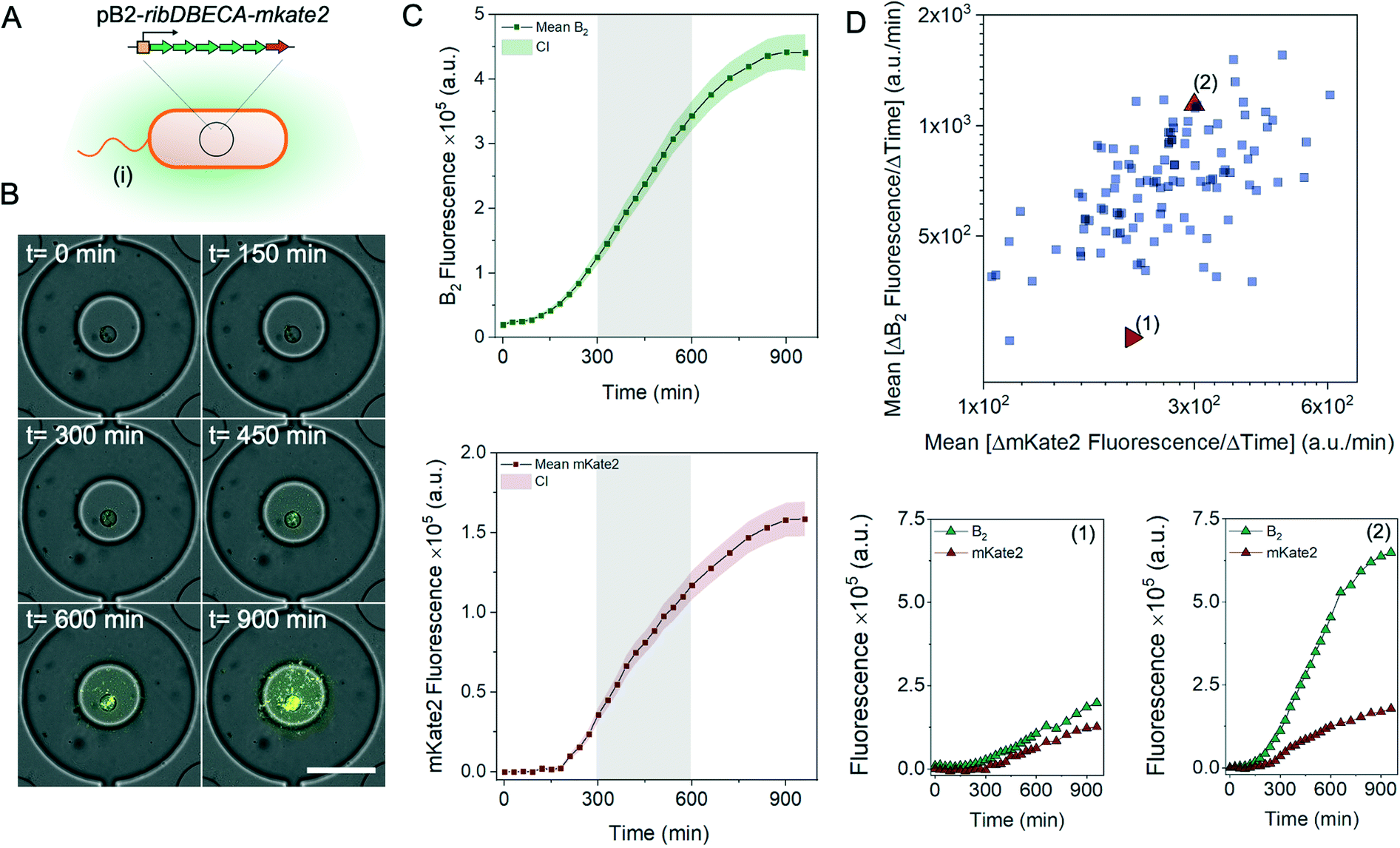 | ||
| Fig. 2 Monitoring the biosynthesis of riboflavin in micro-chambers. A: Pictogram of the E. coli variant (i) BW23474 [pB2-ribDBECA-mkate2]. B: Time-lapse images of a growth chamber during the cultivation. The biomass is visualized via mKate2 fluorescence (orange), and the production of riboflavin is monitored via the autofluorescence (green). Scale bar 100 μm. C: Time-resolved, mean fluorescence measurements with 95% confidence interval (CI) for the basal riboflavin biosynthesis (top panel) and the biomass increase estimated by mKate2 fluorescence (bottom panel) cultivated at 30 °C (n = 111). The highlighted area represents the mid-exponential growth phase, used to form a scatter plot (D). The scatter plot depicts the mean change of the riboflavin and mKate2 fluorescence between 300 and 600 minutes of cultivation, plotted for each chamber. Bottom plots show the time-resolved riboflavin and mKate2 fluorescence changes for two chambers, selected from the different areas of the scatter plot, designated with (1, low biosynthesis rate) and (2, high biosynthesis rate). | ||
The basal riboflavin gene expression (from the leaky promoter) can be increased by addition of the inducer anhydrotetracycline hydrochloride (aTC) which offers a more potent induction of the promoter while being less toxic compared to tetracycline.34 Since riboflavin is fluorescent, the biosynthesis can be directly monitored by fluorescence microscopy. Additionally, the strain produces a red fluorescent protein mKate2 which is used to estimate the biomass increase in the individual micro-cultures.21 During the experiments, the microfluidic cultivation platform is placed on an automated microscope and production as well as growth rates are quantified based on the fluorescent images taken during the cultivation period.
Fig. 2B shows time-lapse images of the selected chamber taken during a 15 hour cultivation period. The figures corroborate the accumulation of the riboflavin inside the chambers together with the increase of bacterial biomass. The time-resolved measurement of the biomass increase (mKate2 production) and the corresponding basal riboflavin biosynthesis using fluorescence microscopy are presented in Fig. 2C. The curves have a similar profile, with the initial lag phase and exponential increase between 200 and 750 minutes; the increase in the biomass is accompanied by an increase in the accumulated riboflavin. The scatter plot (Fig. 2D) summarises the mean production rate and mean biomass increase during the mid-exponential growth phase (between 300 and 600 min) for each individual chamber. The plot displays the intercellular heterogeneity and allows us to distinguish micro-cultures with a particularly increased or decreased riboflavin production (Fig. 2D, bottom panel). In conclusion, we can reliably cultivate bacterial cells in the micro-chambers, while monitoring the biosynthesis of intracellular as well as secreted molecules.
For achieving a high production yield, the timing of inducer supplement is critical, and is typically done in the mid-exponential growth phase (OD600 = 0.5–1).35 The exact time, optimal for the addition of the inducer typically differs for each system, therefore it is important to have an access to the cultivated cells over the entire cultivation time and have the possibility to evaluate the differences in yields resulting from the different induction times. Here, we demonstrate this, and employ the platform to compare riboflavin production with aTC supplement either immediately following the inoculation or after 270 minutes, at the lag or exponential growth phase, respectively.
Fig. 3A shows the time-lapse images for both conditions. As expected, the riboflavin production increased upon the addition of the inducer. However, we observed the growth rate reduction when the inducer was supplied directly after the inoculation, presumably due to the sudden metabolic burden of the gene expression and riboflavin production. In contrast, the inducer supplement during the exponential phase did not impaired bacterial growth, while still led to the riboflavin production increase, about 5-times the signal measured on the basal level (Fig. 3B, S4†). Once the bacteria reach the stationary phase, riboflavin production decreases for the remaining incubation time, what is more apparent with the partial removal of the produced riboflavin from the partially closed chambers. The scatter plot summarising the mean riboflavin and mKate2 production rates between 300 and 600 min for each individual chamber is shown in the Fig. 3C. The scatter plot additionally contains data without the induction for comparison. Both riboflavin and mKate2 production is strongly increased in the chambers supplied with the inducer in the exponential growth phase. The addition of the inducer influences also the production of the mKate2 protein, however, for the comparison among the chambers supplied with the inducer at different time point, mKate2 can be used to estimate the biomass difference (Fig. S4†).
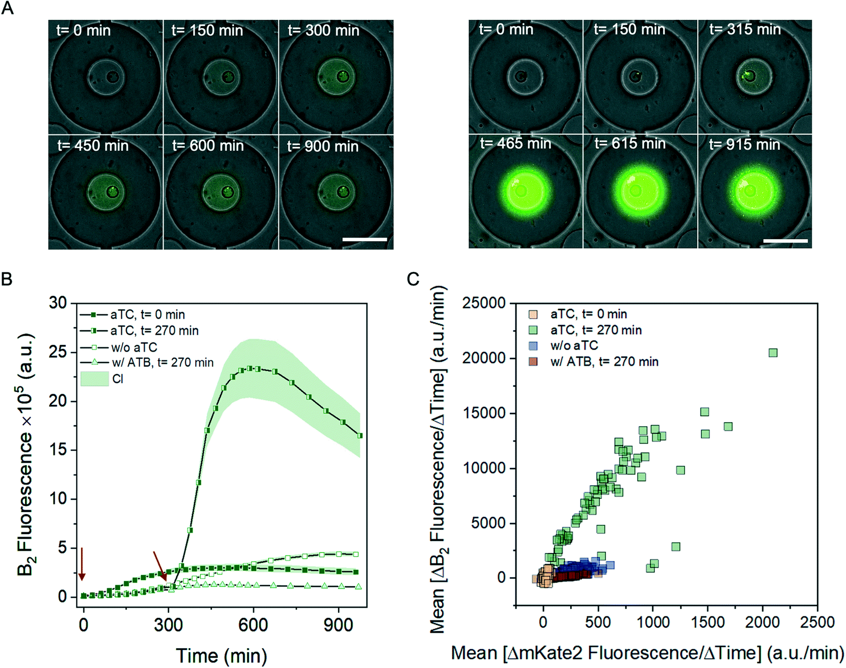 | ||
| Fig. 3 Riboflavin production of E. coli BW23474 [pB2-ribDBECA-mkate2] under different conditions. A: Time-lapse images showing two selected chambers during the 15 h cultivation period. Bacterial growth and therefore bacterial production are reduced when the inducer anhydrotetracycline (aTC) is supplied at the lag phase of the bacterial growth (left panel), in contrast to the expression induced at the exponential phase of the bacterial growth (right panel). The time points as annotated in the figure indicate time from the inoculation, therefore include 15 min delay, needed for the liquid handling during the inducer supplement. Scale bar 100 μm. B: Time-resolved changes of the riboflavin production for the inducer supplement at two different time points, beginning of the culture (t = 0 min; n = 131) and beginning of the exponential phase (after t = 270 min; n = 72), as indicated by the red arrows. The curves showing the production without the induction are identical as for Fig. 2, and were added for the comparison. The graph also contains time-resolved changes of the riboflavin production with the supplement of the antibiotic (ATB) after t = 270 min (n = 196). CI: 95% confidence interval. C: The scatter plot depicts the mean change of the riboflavin and mKate2 fluorescence between 300 to 600 minutes of cultivation, per each chamber for four different conditions: supplement of the inducer directly after the inoculation (yellow), at the exponential growth phase (green), incubation without the inducer (blue) and cells exposed to the antibiotic (red). | ||
We also analysed the biosynthesis under unfavourable conditions by exposing the cells to an antibiotic compound (ampicillin) after 270 min.36 The antibiotic supplement leads to the decreased growth as well as riboflavin production (Fig. 3B and C). The data collected from the mKate2 and riboflavin production (Fig. S4B†) also suggest that about a one-hour exposure is necessary to hinder the bacterial growth and biosynthesis process.
Further, we study riboflavin production for different variants of E. coli BW23474 summarised in the Fig. 4A. The strain variants harboured either plasmid containing a synthetic riboflavin biosynthesis operon ribDBECA leading to a high riboflavin production or an operon ribDBECAPL, lacking the recombinant promoter, therefore exhibiting decreased riboflavin production. The variants also carried the gene for the production of the fluorescent protein mKate2. This gene was either part of the same plasmid as for the riboflavin overproduction, pB2-ribDBECA-mkate2 (i) or was transferred in a separate plasmid, pKD13-mkate2 (ii and iii). Fig. 4B shows time-resolved riboflavin and mKate2 production profiles for these variants.
 | ||
| Fig. 4 Riboflavin biosynthesis for different variants. A: Pictograms of E. coli variants used for the measurements. B: Time-resolved changes of the bacterial growth estimated by mKate2 production (right panel) and riboflavin production (left panel) with 95% confidence interval (CI) measured for the different variants n = 268, 155, 114 for variants (i), (ii) and (iii), respectively. C: Mean riboflavin and mKate2 production for the studied variants at the time point t = 600 min, including statistical analysis (Mann–Whitney U test, at level 0.05). D: The scatter plot representing the mean change of the riboflavin and mKate2 fluorescence over the mid-exponential growth phase (300 to 600 min), per each individual chamber. The measurements were performed in LB, at the 30 °C. | ||
The levels of the produced riboflavin and mKate2 at the end of the cultivation, t = 600 min are summarised in the Fig. 4C. The graph confirms similar production levels of the mKate2 for strains carrying the same plasmid (ii and iii), while the integration of the mKate2 gene to the plasmid carrying genes for riboflavin production lead to significantly higher yields for both compounds. As expected, we observed significantly decreased riboflavin production for the strain containing promoter-less operon (Mann–Whitney U test, at level 0.05). The scatter plot in Fig. 4D shows three different populations corresponding to different variants and highlights differences in the production rates between individual chambers.
Further, we evaluated riboflavin production for the variants without the gene for mKate2 production (Fig. 5A). We compared riboflavin production for the variant containing the plasmid with the gene cluster for the riboflavin overproduction pB2-ribDBECA (iv), a same plasmid without the promoter pB2-ribDBECAPL (v) or plasmid without the genes for riboflavin overproduction, pB2-empty (vi). The results are summarised on the Fig. 5B. Here, we could clearly differentiate the three significantly different production rates, with the highest production rate for the strain with a complete plasmid (iv), followed by the variant containing plasmid missing the promoter (v), while the lowest riboflavin yield was measured for the variant missing the genes for the riboflavin overproduction.
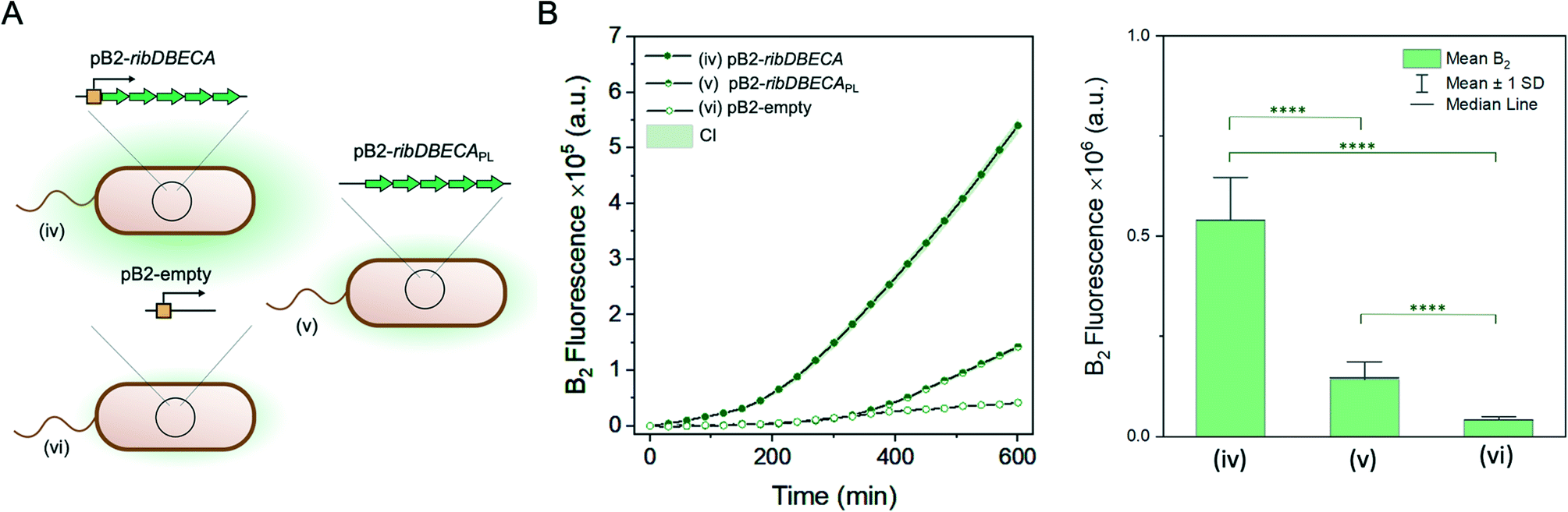 | ||
| Fig. 5 Riboflavin biosynthesis for different variants without mKate2 production. A: Pictograms of E. coli variants (iv–vi) used for the measurements. B: Time-resolved changes of riboflavin production (left panel) with 95% confidence interval (CI) measured for the different variants of E. coli BW23474 (iv–vi), n = 200, 208, 188 respectively. Resulting mean riboflavin production for all the studied variants at the time point t = 600 min (right panel), including the statistical analysis using the Mann–Whitney U test, at level 0.05. The measurements were performed in LB, at the 30 °C. | ||
Finally, we highlight that our platform allows for microscopic monitoring of cell morphology. Here, for one selected variant (ii) BW23474 [pB2-ribDBECA, pKD13-mkate2] we compared the growth and production rate for two cell morphologies that we observed in the growth chambers. Typically, cultivated cells formed small clusters attached to the magnetic beads, surrounded by planktonic cells. However, in 4 out of 155 growth chambers (i.e., 2.6%) we observed also bacterial cells which were not dividing but elongating over the cultivation period (Fig. 6A). The mean mKate2 production for the filamentous cells was slightly lower, however, comparison with all chambers showed that this difference was not significant (Mann–Whitney U test, at level 0.05) (Fig. 6B). Likewise, the mean of riboflavin production (Fig. 6C) was slightly higher for the elongated cells, but this difference was again not significant compared to the values collected from all the chambers (Mann–Whitney U test, at level 0.05). Occasional filamentation has been described before in cultivations where bacteria were trapped in nanochannels,37 and was considered as indicator for the SOS response of bacteria (response to DNA damage). Our data indicate that this filamentation does not affect the production yield, however, the number of chambers with filamentous growth was very low and a more detailed analysis would be required to confirm this conclusion.
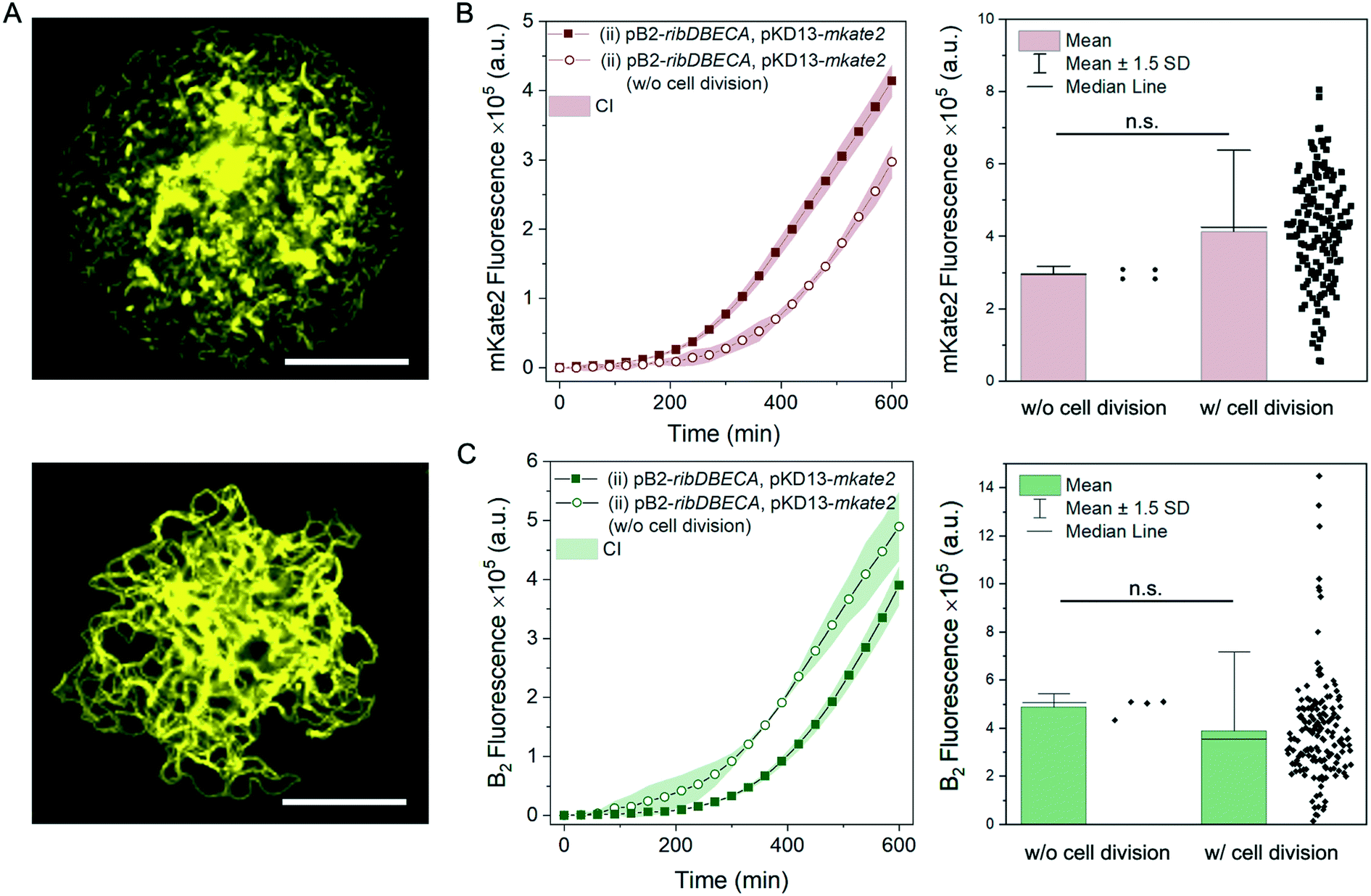 | ||
| Fig. 6 Filamentous growth of the strain BW23474 [pB2-ribDBECA, pKD13-mkate2] (ii). A: Microscopic images of a chamber during the bacterial cultivation; the top image shows culture with small clusters surrounded by the planktonic cells, the bottom figure shows culture without the observed cell division. Scale bar 50 μm. B: Left panel: time-resolved mean mKate2 fluorescence measurements with 95% confidence interval (CI) for the cultures without the observed cell division in comparison with the values obtained from all the chambers. n = 4, 155 respectively. Right panel: comparison between the mKate2 fluorescence for the two morphologies at the t = 600 min, including the individual data points. Statistical analysis was performed using the Mann–Whitney U test, at level 0.05; asymmetric probability, p = 0.065. C: Left panel: time-resolved mean riboflavin fluorescence measurements with 95% confidence interval (CI) for the cultures without the observed cell division in comparison with the values obtained from all the chambers. n = 4, 155 respectively. Right panel: comparison between the riboflavin fluorescence for the two morphologies at the t = 600 min, including the individual data points. Statistical analysis was performed using the Mann–Whitney U test, at level 0.05; asymmetric probability, p = 0.059. | ||
Conclusions
We introduced a miniaturised cultivation platform to study industrially relevant bacterial strains on the micro-culture level. The individual culture sites are formed by round microfluidic valves. The pressure-actuated valves allow us to supply fresh medium and control reagent exchange, e.g. to induce the biosynthesis at a defined point in time, as well as to accumulate product inside the chambers. We studied riboflavin producing E. coli strain and demonstrated the applicability of the platform to recognise the different bacterial populations based on their production profiles, and identify potential outliers with the increased or decreased product synthesis.Incorporating multiple inlets and outlets to the device would allow us to divide the array into segments that could be exposed to different conditions without the risk of cross-contamination and thereby simplify the search for high-producer cells out of a large number of genetic variants.21 Potentially, the products can be collected at the corresponding outlets and subjected to further analysis. Therefore, we believe that the presented platform is a valuable tool to study bacterial cells with industrial importance. Alternatively, in more fundamental studies, it may allow to monitor effects of toxins or antibiotic compounds on microbial populations.
Materials and methods
Materials
Anhydrotetracycline hydrochloride (aTC), ampicillin sodium salt, bovine serum albumin (BSA), LB broth (LB) were purchased from Sigma-Aldrich. Dulbecco's phosphate-buffered saline (PBS, pH 7.0–7.3) was purchased from Gibco (Thermo Fisher Scientific). Polydimethylsiloxane (PDMS) Sylgard 184 kit was purchased from Dow Corning. Glycerol was purchased from ABCR. The kanamycin sulphate (10 mg mL−1), was obtained from Gibco (Life Technologies).The reagent exchange to supplement bacterial culture with the antibiotic, ampicillin sodium salt (50 μg mL−1) was performed in a same way (after 270 minutes).
For the comparison between the different variants of E. coli BW23474 strain (Fig. 4 and 5), we supplied the medium from the syringe and performed the dynamic coating using PBS/BSA solution introduced from the inlet reservoir. During the cultivation, the chambers were after inoculation perfused with LB medium at the flow rate 0.5 μL min−1.
The individual compartments were imaged for a 15 h period (10 h every 30 min, 5 h every 1 h) by brightfield and fluorescence microscopy through a 10× objective (Nikon Plan Fluor). Lumencor Spectra X LED was used as a light source for fluorescence excitation (25% of the maximum light intensity) with corresponding optical filters and dichroic mirrors (riboflavin: cyan LED, 475/28 excitation filter, 495 dichroic, 525/50 emission filter; mKate2: green LED, 549/15 excitation filter, 562 dichroic, 593/40 emission filter). The fluorescence and bright field images were recorded by a Hamamatsu Orca Flash 4 camera (exposure times: 20 ms bright field, 100 ms fluorescence). The microscope was controlled with the NIKON NIS-Elements Advanced Research software. The time-lapse images were acquired using the Nikon Perfect Focus System.
All variants were stored as cryo-stocks containing 25% glycerol (−80 °C). Before the experiments, bacteria were precultured in 2 mL LB media, containing antibiotics for plasmid maintenance: 50 μg mL−1 kanamycin sulphate (variant i, iv–vi); 50 μg mL−1 kanamycin sulphate and 100 μg mL−1 ampicillin sodium salt (variant ii and iii). The bacteria were cultivated at 30 °C using a shaking incubator (Minitron, Infors HT) with a shaking speed of 220 rpm. When an OD600 in the range of 0.4–0.6 was reached, 20 μL of magnetic beads suspension was added to the culture. The bacteria were cultivated at 30 °C under shaking speed of 220 rpm for 30–60 minutes. The bacteria not attached to the magnetic beads were removed in two washing steps (beads were separated in the magnetic field and growth media was replaced with 1 mL of fresh LB). The final volume of the suspension of beads was adjusted to 40 μL.
Funding sources
Financial funding of the Swiss National Foundation (SNF NRP 72, project 407240_167123) and the European Research Council (ERC Consolidator Grant No. 681587) is gratefully acknowledged.Conflicts of interest
There are no conflicts of interest to declare.Acknowledgements
The authors thank the Clean Room Facility and the Single-Cell Facility (both at D-BSSE, ETH Zurich) for their valuable help and advice, particularly Erica Montani and Tom Lummen. The authors also thank Martin Held, Bioprocess laboratory ETH Zurich for valuable discussion.References
- M. M. Zhang, Y. Wang, E. L. Ang and H. Zhao, Nat. Prod. Rep., 2016, 33, 963–987 RSC.
- K. L. J. Prather and C. H. Martin, Curr. Opin. Biotechnol., 2008, 19, 468–474 CrossRef PubMed.
- F. H. Arnold, Angew. Chem., Int. Ed., 2018, 57, 4143–4148 CrossRef CAS PubMed.
- G. Qu, A. Li, C. G. Acevedo-Rocha, Z. Sun and M. T. Reetz, Angew. Chem., Int. Ed., 2020, 59, 13204–13231 CrossRef CAS PubMed.
- D. Binder, T. Drepper, K.-E. Jaeger, F. Delvigne, W. Wiechert, D. Kohlheyer and A. Grünberger, Metab. Eng., 2017, 42, 145–156 CrossRef CAS PubMed.
- T. Jiang, C. Li, Y. Teng, R. Zhang and Y. Yan, Curr. Opin. Biotechnol., 2020, 66, 69–77 CrossRef CAS PubMed.
- P. Rugbjerg and M. O. A. Sommer, Nat. Biotechnol., 2019, 37, 869–876 CrossRef CAS PubMed.
- R. Kwok, Nature, 2010, 463, 288–290 CrossRef CAS PubMed.
- A. Grünberger, W. Wiechert and D. Kohlheyer, Curr. Opin. Biotechnol., 2014, 29, 15–23 CrossRef PubMed.
- O. Scheler, W. Postek and P. Garstecki, Curr. Opin. Biotechnol., 2019, 55, 60–67 CrossRef CAS PubMed.
- C. J. Lyu, L. Liu, J. Huang, W. R. Zhao, S. Hu, L. H. Mei and S. J. Yao, J. Biosci. Bioeng., 2019, 128, 123–128 CrossRef CAS PubMed.
- J. M. Duarte, I. Barbier and Y. Schaerli, ACS Synth. Biol., 2017, 6, 1988–1995 CrossRef CAS PubMed.
- J. J. Agresti, E. Antipov, A. R. Abate, K. Ahn, A. C. Rowat, J. C. Baret, M. Marquez, A. M. Klibanov, A. D. Griffiths and D. A. Weitz, Proc. Natl. Acad. Sci. U. S. A., 2010, 107, 4004–4009 CrossRef CAS PubMed.
- H. A. Bunzel, X. Garrabou, M. Pott and D. Hilvert, Curr. Opin. Struct. Biol., 2018, 48, 149–156 CrossRef CAS PubMed.
- A. Kulesa, J. Kehe, J. E. Hurtado, P. Tawde and P. C. Blainey, Proc. Natl. Acad. Sci. U. S. A., 2018, 115, 6685–6690 CrossRef PubMed.
- H. F. Chan, S. Ma, J. Tian and K. W. Leong, Nanoscale, 2017, 9, 3485–3495 RSC.
- C. S. Karamitros, M. Morvan, A. Vigne, J. Lim, P. Gruner, T. Beneyton, J. Vrignon and J. C. Baret, Anal. Chem., 2020, 92, 4908–4916 CrossRef CAS PubMed.
- L. Shang, Y. Cheng and Y. Zhao, Chem. Rev., 2017, 117, 7964–8040 CrossRef CAS PubMed.
- E. M. Payne, D. A. Holland-Moritz, S. Sun and R. T. Kennedy, Lab Chip, 2020, 20, 2247–2262 RSC.
- G. Leonaviciene, K. Leonavicius, R. Meskys and L. Mazutis, Lab Chip, 2020, 20, 4052–4062 RSC.
- P. Jusková, Y. R. F. Schmid, A. Stucki, S. Schmitt, M. Held and P. S. Dittrich, ACS Appl. Mater. Interfaces, 2019, 11, 34698–34706 CrossRef PubMed.
- Y. Tang, M. Gan, Y. Xie, X. Li and L. Chen, Lab Chip, 2014, 14, 1162–1167 RSC.
- A. Groisman, C. Lobo, H. J. Cho, J. K. Campbell, Y. S. Dufour, A. M. Stevens and A. Levchenko, Nat. Methods, 2005, 2, 685–689 CrossRef CAS PubMed.
- M. C. Hesselman, D. I. Odoni, B. M. Ryback, S. de Groot, R. G. A. van Heck, J. Keijsers, P. Kolkman, D. Nieuwenhuijse, Y. M. van Nuland, E. Sebus, R. Spee, H. de Vries, M. T. Wapenaar, C. J. Ingham, K. Schroën, V. A. P. Martins dos Santos, S. K. Spaans, F. Hugenholtz and M. W. J. van Passel, PLoS One, 2012, 7, e36982 CrossRef CAS PubMed.
- J. Lee, M. Kim, J. Park and T. Kim, Lab Chip, 2016, 16, 1072–1080 RSC.
- M. Kim, J. W. Lim, H. J. Kim, S. K. Lee, S. J. Lee and T. Kim, Biosens. Bioelectron., 2015, 65, 257–264 CrossRef CAS PubMed.
- E. Kaganovitch, X. Steurer, D. Dogan, C. Probst, W. Wiechert and D. Kohlheyer, New Biotechnol., 2018, 47, 50–59 CrossRef CAS PubMed.
- A. Grünberger, N. Paczia, C. Probst, G. Schendzielorz, L. Eggeling, S. Noack, W. Wiechert and D. Kohlheyer, Lab Chip, 2012, 12, 2060–2068 RSC.
- M. Kim, J. W. Lim, S. K. Lee and T. Kim, Anal. Chem., 2017, 89, 10286–10295 CrossRef CAS PubMed.
- S. Stratz, K. Eyer, F. Kurth and P. S. Dittrich, Anal. Chem., 2014, 86, 12375–12381 CrossRef CAS PubMed.
- L. Armbrecht, R. S. Müller, J. Nikoloff and P. S. Dittrich, Microsyst. Nanoeng., 2019, 5, 55 CrossRef CAS PubMed.
- R. Lutz and H. Bujard, Nucleic Acids Res., 1997, 25, 1203–1210 CrossRef CAS PubMed.
- R. Bertram and W. Hillen, Microb. Biotechnol., 2008, 1, 2–16 CrossRef CAS PubMed.
- J. Degenkolb, M. Takahashi, G. A. Ellestad and W. Hillen, Antimicrob. Agents Chemother., 1991, 35, 1591–1595 CrossRef CAS PubMed.
- M. R. Green and J. Sambrook, Molecular Cloning: A Laboratory Manual, Cold Spring Harbor Laboratory Press, 4th edn, 2012 Search PubMed.
- J. Blázquez, J. Rodríguez-Beltrán and I. Matic, Annu. Rev. Microbiol., 2018, 72, 209–230 CrossRef PubMed.
- P. Wang, L. Robert, J. Pelletier, W. L. Dang, F. Taddei, A. Wright and S. Jun, Curr. Biol., 2010, 20, 1099–1103 CrossRef CAS PubMed.
- A. Haldimann, M. K. Prahalad, S. L. Fisher, S. K. Kim, C. T. Walsh and B. L. Wanner, Proc. Natl. Acad. Sci. U. S. A., 1996, 93, 14361–14366 CrossRef CAS PubMed.
- S. Schmitt, M. Walser, M. Rehmann, S. Oesterle, S. Panke and M. Held, Sci. Rep., 2018, 8, 1–9 CAS.
- J. C. Anderson, Anderson promoter collection, Retrieved July 8, 2021, http://parts.igem.org/Promoters/Catalog/Anderson.
- J. Schindelin, I. Arganda-Carreras, E. Frise, V. Kaynig, M. Longair, T. Pietzsch, S. Preibisch, C. Rueden, S. Saalfeld, B. Schmid, J.-Y. Tinevez, D. J. White, V. Hartenstein, K. Eliceiri, P. Tomancak and A. Cardona, Nat. Methods, 2012, 9, 676–682 CrossRef CAS PubMed.
Footnote |
| † Electronic supplementary information (ESI) available. See DOI: 10.1039/d1lc00621e |
| This journal is © The Royal Society of Chemistry 2021 |