
 Open Access Article
 This Open Access Article is licensed under a
 Creative Commons Attribution 3.0 Unported Licence
Increasing the sensitivity of micro X-ray fluorescence spectroscopy through an optimized adaptation of polycapillary lenses to a liquid metal jet source†
Leona J.
Bauer
 *ab,
Richard
Gnewkow
ab,
Frank
Förste
a,
Daniel
Grötzsch
a,
Semfira
Bjeoumikhova
c,
Birgit
Kanngießer
a and
Ioanna
Mantouvalou
ab
*ab,
Richard
Gnewkow
ab,
Frank
Förste
a,
Daniel
Grötzsch
a,
Semfira
Bjeoumikhova
c,
Birgit
Kanngießer
a and
Ioanna
Mantouvalou
ab
aInstitute for Optics and Atomic Physics, Technical University of Berlin, Hardenbergstr. 36, Berlin 10623, Germany. E-mail: leona.bauer@helmholtz-berlin.de
bHelmholtz Zentrum Berlin, Albert-Einstein-Str. 15, Berlin 12489, Germany
cHelmut Fischer GmbH, Institut für Elektronik und Messtechnik, Rudower Chaussee 29-31, Berlin 12489, Germany
First published on 11th October 2021
Abstract
The combination of brilliant liquid metal jet sources (LMJS) and polycapillary lenses yields substantial advantages in the excitation efficiency of traces of transition metals by micro-X-ray fluorescence spectroscopy (μXRF) and confocal μXRF in the laboratory. We show, that it is possible to especially adapt the parameters of polycapillary lenses to achieve an optimized performance in transmission and exit focal spot size. Furthermore, we demonstrate an energy dependent influence of the source spot size on the effective transmission of the lenses, which increases with decreasing field of view of the polycapillary lenses. A measurement on a mussel foot cross section using a μXRF setup with a specially designed polycapillary lens in combination with the LMJS shows a significant increase of the excitation efficiency for vanadium. A 24 times higher net peak fluorescence intensity for V K radiation is achieved resulting in well-defined and detailed vanadium structures compared to measurements performed with a state-of-the-art μXRF setup.
Introduction
Micro-X-ray fluorescence spectroscopy (μXRF) and confocal μXRF are non-destructive techniques which enable the measurement of elemental distributions in one, two or three dimensions with a resolution in the micrometer regime.1 The non-destructiveness and minimal sample preparation has led to a widespread use in various application fields.2–5 To facilitate these two techniques, X-ray radiation is focused on a sample and polychromatic fluorescence radiation is detected by an energy dispersive detector. For confocal μXRF an additional lens in front of the detector is utilized to create a small probing volume from which fluorescence information in first approximation is obtained only.μXRF and confocal μXRF setups in the laboratory predominantly use X-ray tubes as sources in combination with a polycapillary full lens and a polycapillary half lens in the excitation and detection path, respectively. Polycapillary lenses allow to focus and collect a wide energy bandwidth at once6 with a high efficiency and exit focal spot sizes in the range of about 10 μm to 60 μm.7,8 For μXRF the wide bandwidth is necessary in the excitation channel to have an efficient transmission of the polychromatic excitation of X-ray tubes. For confocal μXRF a wide bandwidth is even a prerequisite because it renders the simultaneous detection of many fluorescence energies feasible. As a consequence, almost all confocal setups, also when using monochromatic excitation, use polycapillary lenses to collect the fluorescence radiation in the detection channel.9,10
In these lenses, X-rays are transported through total external reflection in bundles of bent hollow glass capillaries. Due to the energy dependence of the critical angle for total reflection the transmission and the focal spot sizes are energy dependent.6,11,12 The design of the polycapillary lenses can be adapted for special measurement needs.13,14 The main geometric parameters are the length, the curvature of the capillaries, the entrance, exit and maximum diameter and the focal distances. By changing these parameters, the focal spot size and the acceptance solid angle can be varied. The entrance focal spot size, from which radiation can be collected by the polycapillary, is mainly determined by the length of the entrance focal distance. The achievable spot size in the exit focus, is mainly determined by the exit focal distance and the curvature of the capillaries.13
Novel brilliant X-ray sources, which use a liquid Ga–In alloy as anode material are a promising upgrade for laboratory μXRF and especially confocal μXRF setups.15 Conventional X-ray tubes using solid anodes suffer from electron beam power density restrictions due to thermal heating possibly leading to melting of the anode material.16 Due to this, commonly used microfocus X-ray tubes with a source spot size of 50 μm × 50 μm are operated with a maximum power of 30 W to 50 W,17 resulting in an electron beam power density of ∼15 kW mm−2. The highest reported electron beam power values for microfocus X-ray tubes are 125 kW mm−2 (20 μm × 20 μm source spot size at 50 W). While X-ray tubes with rotating anode materials can be operated at electron beam power density values of ∼400 kW mm−2 (1.2 kW, 70 μm source spot size),18 liquid metal jet sources, where the anode material is permanently replaced are commonly operated with electron beam power density values of ∼830 kW mm−2 at 250 W, with a significant smaller effective source spot size of 20 μm × 20 μm.
The small source spot size and the energy of the characteristic K lines of Ga which can be transported very efficiently through polycapillary lenses19 allow in theory to specially adapt the parameters of the lens to the LMJS properties resulting in a very efficient excitation of transition metals from scandium to copper.
In this publication, we measure the performance of different types of polycapillary lenses in combination with a LMJS in a 90° μXRF geometry. We use variations of the source spot size to examine its influence on the performance of the polycapillary lenses. Therewith, we want to investigate the option of adapting the source spot size, which is in general directly connected to the possible electron beam power, and the parameters of the used polycapillary lens to fit best to the desired measurement needs. In the end, we show μXRF measurements on a bio-tissue sample from a marine mussel as an application example for the excitation efficiency of the new spectrometer for the localization of transition metals. Especially, the distribution of traces of vanadium in the biological matrix as investigated already in a previous work20 show the added value facilitated by the optimized excitation conditions.
Experimental
Setup
A μXRF setup was built up using a LMJS (type D2+, Excillum Inc.), a 30 mm2 energy dispersive SDD detector (XFlash 1001, Bruker Nano GmbH) and different types of polycapillary lenses (Helmut Fischer GmbH). The setup incorporates a 90° geometry between excitation and detection path with the sample at 45° from both and an X-ray diode (xPIN, Rigaku) behind the sample for alignment purposes, see Fig. 1. All components can be moved with motorized precision stages (Owis GmbH, PI miCos GmbH) and the whole setup is housed in a radiation protection chamber with lead protection windows and walls.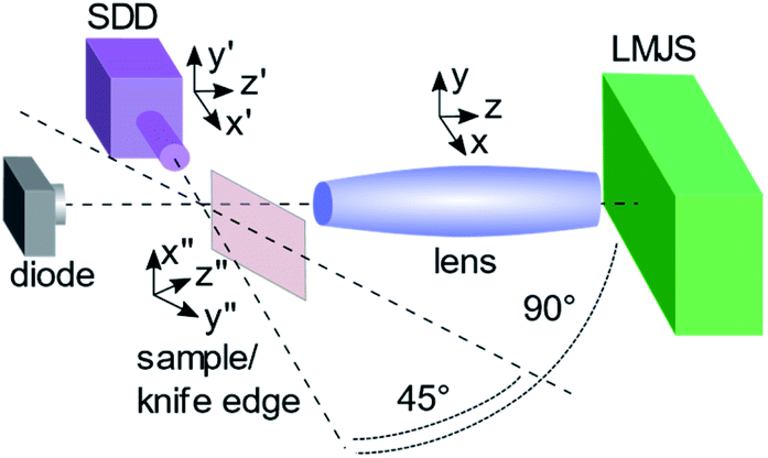 | ||
| Fig. 1 Schematic μXRF setup. A polycapillary lens is placed in front of the LMJS. In 90° to the excitation path the energy dispersive SDD detector is placed and in 45° to the excitation and detection path the sample is placed. Polycapillary lens, detector and sample are placed on motorized stages for the alignment of the setup. A photo diode is placed in the excitation beam after the polycapillary lens for the alignment and to control the alignment during the measurements. | ||
The LMJS uses a 95% gallium and 5% indium alloy. It is operated at 70 kV with adjustable current reaching a maximum power of 250 W with a typical electron beam size of 80 μm × 20 μm resulting in a 20 μm × 20 μm effective source spot size. The electron beam is not centered on the metal jet but shifted by 20 μm in direction to the exit window to minimize absorption effects (see ESI, Section S1†). As specific feature of the LMJS the effective source spot size can be changed easily in a certain range by changing the focusing parameters of the electron beam. Depending on the current evaporation state of the cathode's surface the LMJS has a specific minimal stable electron beam spot size. The LMJS has an effective minimal possible source spot size of 15 μm × 15 μm with a restricted maximum power of 47 W to avoid damaging the source by generating metal vapor at too high anode power loading. By changing the width of the electron beam absorption effects need to be considered, which are further described in ESI (Section S1†). Therefore, in the following only the height of the source spot is changed.
For the alignment of the setup, in a first step, the polycapillary lens is placed in a holder on three motorized linear stages in front of the shutter system of the LMJS. Using the X-ray photo diode, which is placed in the excitation beam after the polycapillary lens, the lens is aligned to the maximum intensity by scanning in three directions (x, y, z, see Fig. 1). The photo diode remains in the setup to control the alignment during the measurements. As a second step the detector is placed at 90° from the excitation path oriented to the visually estimated focus position of the polycapillary lens. Using a razor blade, which is mounted on the sample holder at 45° from the excitation and detection path, knife edge scans in fluorescence mode are performed to find the focal position of the polycapillary lens. Having the razor blade in the focus position, the detector is aligned in y′ and z′ direction (see Fig. 1) to maximum intensity. The sample to detector distance x′ is defined through the geometric arrangement.
To illustrate the performance of the μXRF setup with the optimized polycapillary lens, a commercial M4 Tornado setup is used for comparison.1 The spectrometer is equipped with a microfocus Rh X-ray tube, allowing a maximum power of 50 W (50 kV, 1 mA) with a source spot size of 50 μm × 50 μm, a focusing polycapillary lens with an optimized focus size (full width half maximum (FWHM) @ Fe Kα = (32.5 ± 2.5) μm) and a 30 mm2 SDD. The efficiencies of both SDD's were compared by the measurement of one thick multi-element glass reference sample (XRF-PB3 from Breitländer GmbH), resulting in a roughly 12% higher efficiency of the M4 SDD compared to the one used in the LMJS setup.
Polycapillary lenses
The parameters of the four different types of polycapillary full lenses are listed in Table 1. The lenses are all made of borosilicate glass, but differ in size, capillary diameter, focal distances and the size of the acceptance solid angle. The first one (A) is an especially adapted lens designed for the LMJS, which was already used in a previous confocal μXRF setup.15 This lens' maximal transmission was designed to be in the range of the energy of the Ga K fluorescence lines and the first focal length was minimized according to the LMJS geometry constraints. The second one (B) is a lens which is typically used for commercial μXRF setups as the M4 Tornado. This type of lenses has defined size parameters to fit into the geometry of the commercial setups, compromising between good values for transmission and exit focal spot size. The third one (C) is a micro lens, which is the smallest one and designed to create a minimal exit focal spot size. All three lenses are filled with He. The fourth lens (D) has in contrast to the other lenses no beryllium windows (thus no He filling) and is longer for the use in scanning electron microscopes (SEM).| Lens no. | F 1/mm | L/mm | F 2/mm | D in/mm | D out/mm | D max/mm | D cap/μm | Ω L/sr |
|---|---|---|---|---|---|---|---|---|
| A: 280mls19 | 32 | 116 | 5.4 | 4.1 | 1.65 | 7.35 | 9 | 0.01289 |
| B: 250mls03 | 55 | 94 | 10.0 | 5.7 | 2.1 | 7.4 | 5 | 0.00873 |
| C: 244mkl41 | 51 | 63 | 2.8 | 3.4 | 1.1 | 4.3 | 9 | 0.00349 |
| D: 231mls25 | 215 | 178 | 6.5 | 5.8 | 1.5 | 7.0 | 9 | 0.00057 |
Samples and measurements
Different characterization and one application measurements were performed. The characterization measurements provide the comparison of the values for the transmission and exit focal spot size of the different types of lenses. To determine the transmission both scattering and fluorescence measurements were performed. Three different types of samples were used for the characterization measurements: the first one (i) is a thick custom-made plastic (PVC) sample (Helmut Fischer GmbH) which can be placed directly on the detector snout and is used as scatterer. The sample has an aperture with a diameter of 7 mm. This sample was measured in μXRF mode with all polycapillary lenses with a power of 15 W using measurement life times of 30 s, 60 s and 140 s. Additionally, the sample is measured in the same geometry after removing the lenses with a power of 5 W or 15 W and measurement life times of 30 s and 55 s. The power values were adapted to the detected count rate to avoid a dead time higher than 75%.The second set of samples (ii) is a collection of 18 thick single element samples (Bruker Nano GmbH), covering a wide energy range. These samples were measured with the different lenses at 30 W using measurement life times of 20 s to 60 s. The third one (iii), a commercially available razor blade, which is mainly composed of chromium and iron, is used for knife edge scans in fluorescence mode. The knife edge scans were performed by scanning the razor blade in x′′ direction at several z′′ positions (see Fig. 1) with a step size of 5 μm or 10 μm, measurement life times of 10 s and a power of 25 W.
As application sample (iv), a mussel foot cross section was investigated. Marine mussels have an organ called foot, which is involved in the production of the adhesive byssus fibers, which are used by the mussel to attach itself to its habitats. The understanding of the production of these fibers in the foot is of interest due to their excellent mechanical properties leading to the possibility to design e.g. bio-inspired adhesives, coatings and metallopolymers.20
Here, a 200 μm thick, freeze-dried cross section was prepared on carbon tape. The sample was scanned at a maximum power of 250 W and 20 μm × 20 μm effective source spot size in x′′ and y′′ direction using a step size of 30 μm and a measuring time of 15 s per measurement point. The application sample was measured additionally with the M4 Tornado with the same parameters but a power of 50 W.
Transmission calculation
In general, the energy dependent transmission T(E) of a polycapillary lens is defined as the ratio between the intensity of the radiation which is transported to the focus and the intensity of the radiation which illuminates the entrance of the lens. The latter is described by the emission of the source multiplied with the acceptance solid angle ΩL of the lens. Therewith, the transmissions of polycapillary lenses with different acceptance solid angles are normalized to this angle, preventing a comparison of the absolute value of the transported radiation intensity from the source to the focus between different polycapillary lenses. For an absolute comparison we therefore define an effective transmission Teff(E) = T(E)ΩL.In the following the transmission of a polycapillary lens is derived from the measured data in two ways. One simple way is to use the scattering measurement on the plastic sample (i) with and without lens. The plastic sample acts as a pure scatterer, so that a measured spectrum mirrors the Compton shifted excitation spectrum. To derive the effective transmission, first, a spectrum measured without lens is divided by the solid angle which is defined by the aperture of sample (i) and the distance between source and sample. Then, the ratio of the spectrum with lens which includes the acceptance solid angle of the lens and this spectrum is fitted with the Gumbel function TA,Ec,w without offset,21 which is an asymmetric peak function:
TA,Ec,w(E) = A![[thin space (1/6-em)]](https://www.rsc.org/images/entities/char_2009.gif) e−e−z−z+1 e−e−z−z+1 | (1) |
| z = (E − Ec)/w | (2) |
The parameters describe the amplitude A, the center position Ec and the width w of the peak function. The result is a curve which roughly describes the effective transmission of the polycapillary lens with an energy-dependent Compton shift to lower energies.
The second way is based on fluorescence measurements. Single spectra measured on different pure element reference samples (ii) are deconvolved using an in house program to receive the net peak intensities. In this program, first, the background is fitted using a strip algorithm and subtracted from the measured spectrum. Then, the intensity peaks of selected energy lines are fitted with a Gaussian function considering fundamental parameters accessed from the xraylib data base.22 The area of the Gaussian function gives the net peak intensity. In the following the net peak intensities of Kα line and Kβ line are summed and labelled as K lines. The Sherman equation23 for thick samples is then used to calculate net peak intensities Ii(Ei) of the given samples using the properties of the setup used for the measurements:21
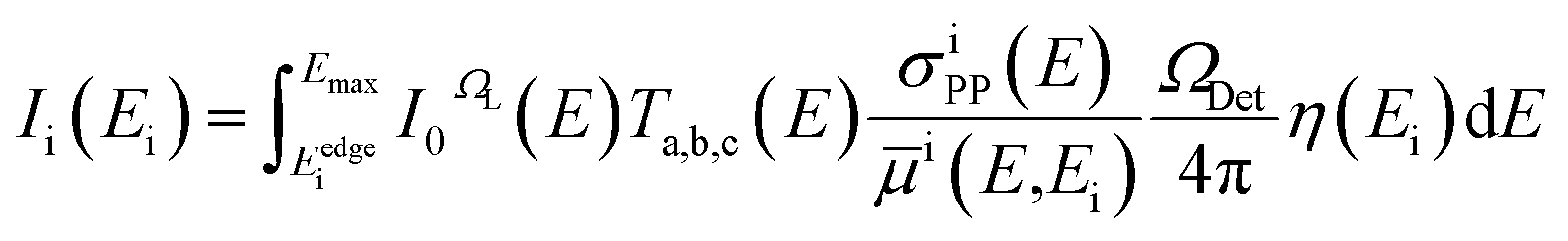 | (3) |
As excitation spectrum I0ΩL(E), a Monte Carlo simulated spectrum from the manufacturer with the parameters from the used LMJS (see Table 2) from 8 keV to 70 keV, was supplemented with calculated values using the Elam data base24 from 2 keV to 8 keV. The acceptance angle of the used polycapillary lenses ΩL is used to define the solid angle of the excitation spectrum. The detector efficiency η(Ei) and the solid angle of detection ΩDet are calculated from detector parameters (see Table 2). Using the Elam data base the photo production cross sections σiPP(E) and the effective linear mass absorption coefficient ![[small mu, Greek, macron]](https://www.rsc.org/images/entities/i_char_e0cd.gif) i(E,Ei) are calculated for certain fluorescence lines Ei. The energy dependent transmission Ta,b,c(E) of the polycapillary lens can be approximated by the Gumbel function TA,Ec,w(1). The three parameters A, Ec and w are used as fitting parameters in the Sherman equation (3).
i(E,Ei) are calculated for certain fluorescence lines Ei. The energy dependent transmission Ta,b,c(E) of the polycapillary lens can be approximated by the Gumbel function TA,Ec,w(1). The three parameters A, Ec and w are used as fitting parameters in the Sherman equation (3).
| Excitation spectrum | Detector efficiency | ||
|---|---|---|---|
| Max. voltage & current | 70 kV & 3.57 mA | Solid angle | 0.012 rad |
| e-Beam width & height | 80 μm & 20 μm | Chip thickness | 0.3 cm |
| e-Beam offset | 20 μm | Excitation & detection angle | 45° & 45° |
| Effective source spot size | 20 × 20 μm | Window | Be, 8 μm |
| e-Beam & take off angle | 90° & 15° | ||
| Window | Be, 127 μm & C, 20 μm | ||
In an iterative calculation, net peak intensities are calculated, compared to the measured intensities and then the parameters in the transmission function are adapted, so that the results fit best to the measured net peak intensities. The resulting Gumbel function gives an approximation of the energy dependent transmission of the lens. By multiplying this transmission function with the solid angle of acceptance of the lens the effective transmission is derived, which can be directly compared to the effective transmission derived from scattering measurements.
Results and discussion
Characterization
As described before the Gumbel functions as approximation of the transmission of the polycapillary lenses are calculated from the measurements on sample set (i) and (ii). For sample set (i) the solid angle of acceptance is already included in the resulting Gumbel function due to the normalization of the measured spectra to this solid angle. For sample set (ii) the resulting Gumbel functions were multiplied by the solid angles of acceptance (Table 1) to receive the effective transmission of the lenses which is shown in Fig. 2 on the left side. Additionally, the uncertainties of the fit algorithm are depicted with thinner lines in the same colors as the resulting curves. The parameters of the Gumbel functions and their uncertainties are listed in Table S1 in the ESI.† The optimized lens (A) shows the highest effective transmission, closely followed by the M4 like lens (B) with 20% decreased effective transmission regarding the Ga K line energies. The SEM like lens (D) has the lowest effective transmission (roughly a factor 20 less than the optimized lens) which is caused by the very small solid angle of acceptance. The micro lens has a higher effective transmission than the SEM like lens, but four times less than the optimized lens.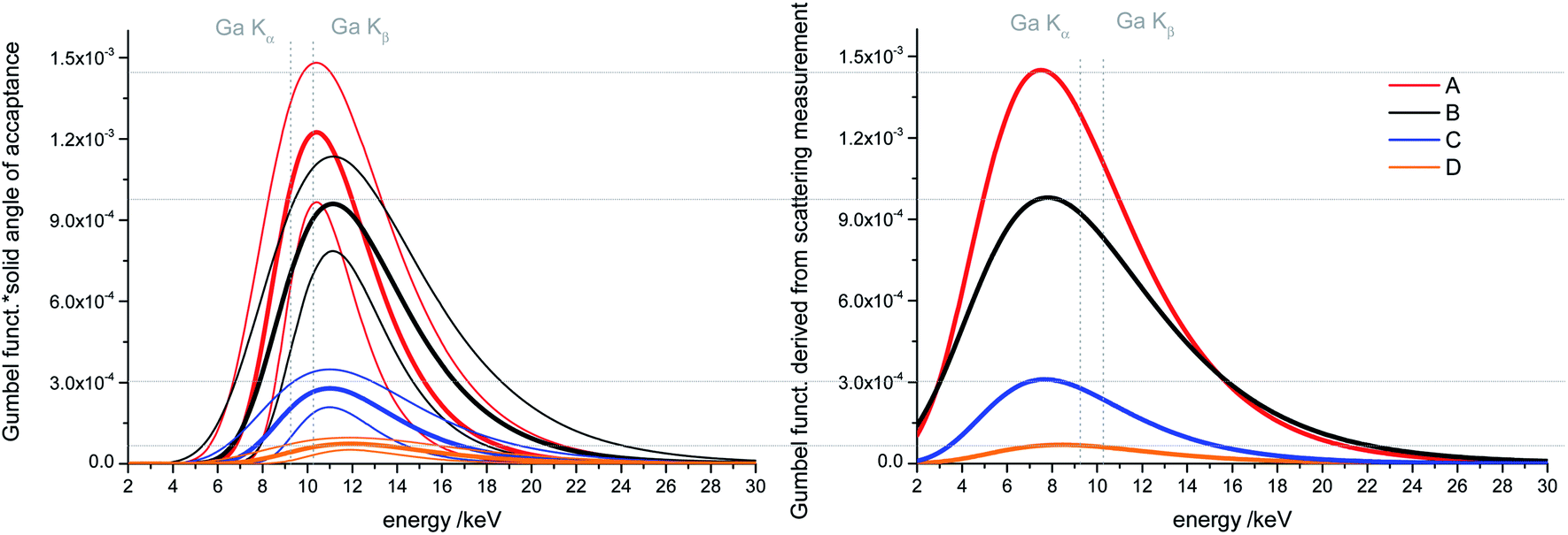 | ||
| Fig. 2 Energy dependent effective transmission of the polycapillary lenses. Left: Calculated transmission functions of the polycapillary lenses multiplied by the acceptance solid angle of the lenses. As transmission function, a Gumbel function is approximated, which is determined by comparing theoretically calculated intensities and measured fluorescence intensities of single element reference samples with the parameters in the Gumbel function as fitting parameters. The thinner lines display the uncertainties of the fit algorithm. Right: Gumbel functions derived from scattering measurements with and without lens, collected in μXRF geometry using a thick plastic sample. | ||
On the right-hand side of Fig. 2 the Gumbel functions derived from the scattering measurements on the plastic sample (i) are depicted. Clearly visible is a broadening and a shift to lower energies of the peak function compared to the curves derived from fluorescence measurements. To some extent, this can be explained by Compton scattering but additionally, the Gumbel function does not fit very well to the ratio of the two measurements due to high noise in the lower energy range (2 to 5 keV) and artefacts from characteristic and pile up peaks (see an example curve and fit in Fig. S2 in the ESI†). Nevertheless, the Gumbel functions show the same trend as the ones derived by fluorescence measurements and the absolute effective transmission values agree with the ones derived from fluorescence measurements in the range of the error limits.
In Fig. 3 the FWHM values for the Fe K lines as result of several knife edge scans on a razor blade in fluorescence mode along the z′′ axis (see Fig. 1) are shown. The FWHM values were derived by fitting a Gaussian function to the derivative of the Fe K lines net peak intensity distribution along the z′′ axis. The measured values are approximated with a second order polynomial to visualize the trend beyond the measured values. The horizontal lines depict the values derived from the certification of the manufacturer for the energy range of 5 keV to 7.5 keV. They were obtained by a Rh microfocus X-ray tube and additionally by a Cu microfocus X-ray tube for the optimized lens (A), where both tubes have typical source spot sizes of 50 μm × 50 μm. In Table 3 the FWHM values in the focus position for Fe K lines and Cr K lines and the values of the certification are listed.
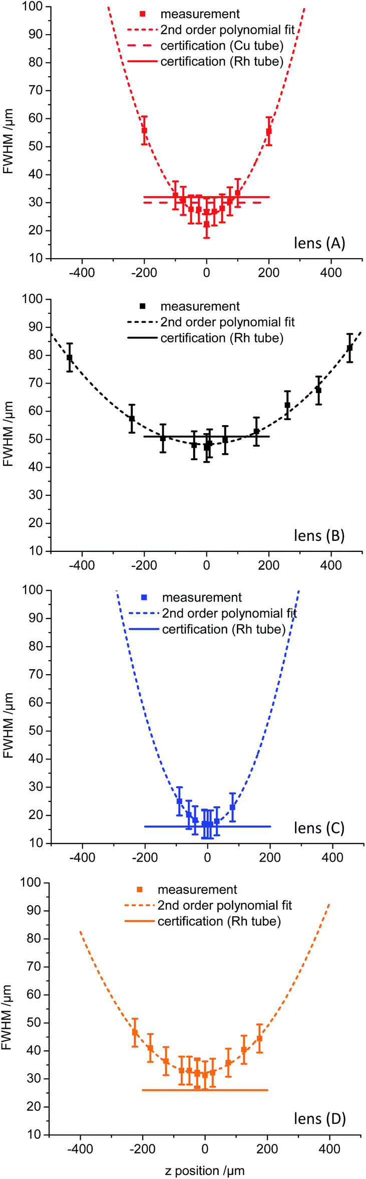 | ||
| Fig. 3 FWHM values for Fe Kα derived from knife edge scans on a razor blade in fluorescence mode for several positions along the X-ray beam focused by the polycapillary lenses. The measurement points were fitted by a second order polynomial to visualize the differences between the lenses. The horizontal lines depict the values derived from the certification, which are additionally listed in Table 3. | ||
| FWHM/μm | |||||
|---|---|---|---|---|---|
| Knife edge scan | Certification | ||||
| Source | LMJS | LMJS | Rh tube | Cu tube | |
| Energy | Cr Kα | Fe Kα | (5–7.5) keV | (5–7.5) keV | |
| Lens | A | 25 ± 5 | 22 ± 5 | 32 ± 5 | 30 ± 5 |
| B | 49 ± 5 | 47 ± 5 | 51 ± 5 | — | |
| C | 19 ± 5 | 17 ± 5 | 16 ± 5 | — | |
| D | 33 ± 5 | 30 ± 5 | 26 ± 5 | — | |
As expected, the micro lens (C) has the smallest exit focal spot size (17 μm ± 5 μm), the M4 like lens (B) has the biggest focal spot (47 μm ± 5 μm) and the optimized lens (A) lies with 22 μm ± 5 μm in between the micro and the SEM like lens (D) (30 μm ± 5 μm). In general and in regard to the uncertainties, the measurements validate the given values from the certificate and there is no systematic effect of the 2.5 times smaller source spot size of the LMJS visible.
Variation of the source spot size
To further investigate the effect of the source spot size on the performance of the polycapillary lenses, the source spot size was varied and the sample sets (i), (ii) and (iii) were again measured. In Fig. 4 net peak intensities derived by deconvoluting from the measured spectra are plotted against the absorption edge energy of the certain elements derived from sample set (ii) for the effective source spot sizes 25 μm × 25 μm and 25 μm × 100 μm for the SEM like (D), the micro (C) and the optimized lens (A). By increasing the height of the source spot size an intensity decrease is visible for all lenses. Exemplary, the intensity decrease is shown for the Cu K fluorescence intensity in percent. With decreasing entrance focal distance resulting in a smaller field of view of the polycapillary lenses, the intensity loss by changing the source spot size is more prominent. Thus, the impact on the SEM like lens is very small (7% decrease for Cu K) and considerably higher for the optimized lens (42% decrease for Cu K).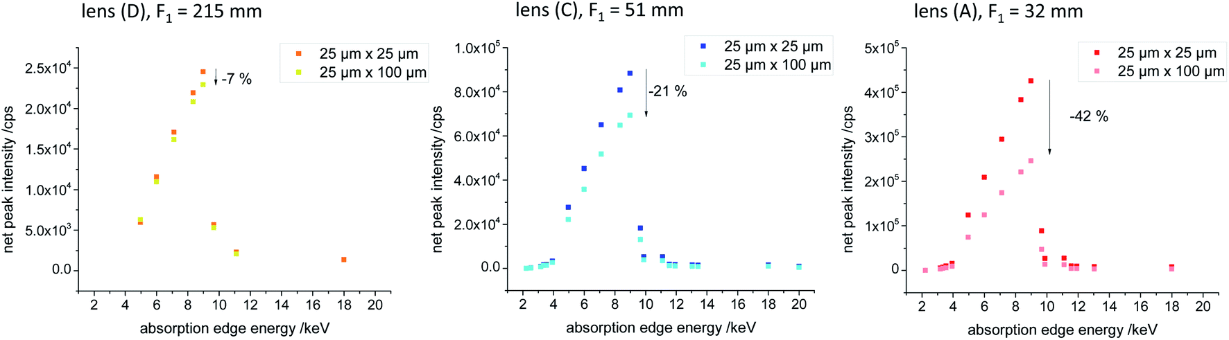 | ||
| Fig. 4 The graphs show net peak intensities of point measurements on single element reference samples in μXRF geometry using two different effective source spot sizes of the LMJS. The effective source spot sizes (width × height) are 25 μm × 100 μm and 25 μm × 25 μm. Exemplarily the intensity differences between the measurements with different effective source spot sizes are marked and the entrance focal distance F1 is given. | ||
In Fig. 5, top row, the measured spectra on the plastic sample (i) are shown for the micro and the optimized lens for effective source spot size values ranging from 20 μm × 20 μm to 20 × 150 μm. Again there is a decrease of intensity with increasing source spot size visible. To depict the influence of the source spot size variation in regard to the energy of the transported X-rays, we have chosen regions of interest (ROI), with a width of 3 keV and summed up the measured intensities in these ROIs. In Fig. 5, bottom row, the summed intensities are plotted as a function of the used source spot height. For the micro lens, which has a bigger focal distance to the source, there seems to be a plateau were the source spot size does not affect the transmission (from a height of the source spot of roughly 20 μm to 50 μm). In case of the optimized lens, there is a loss in intensity visible as soon as the source spot size is increased, especially for higher energies.
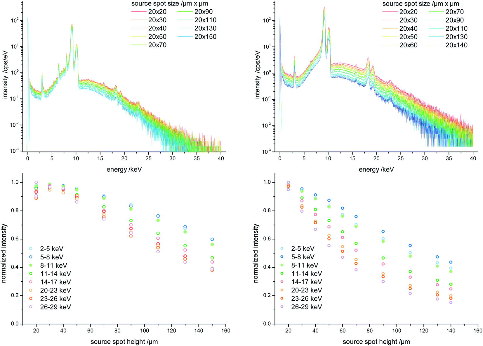 | ||
| Fig. 5 Acceptance of the polycapillary lenses (left: lens (C), right: lens (A)). Top: Scattered excitation spectra measured in μXRF geometry using the plastic sample (i) and varied source spot sizes. Bottom: Integrated intensities concerning different energy regions (3 keV range) plotted against the varied source height. The region of 17 keV to 20 keV is excluded due to pile up effects of the Ga K lines. | ||
The results for the FWHM values for the Fe K lines which were derived from knife edge scans on a razor blade in fluorescence mode by varying the source spot size for the SEM like lens and the micro lens (see ESI, Fig. S3†) show that the exit focal spot size of the lens is not influenced by the source spot size.
μXRF
As application example, we measured a mussel foot cross section with the M4 Tornado and the LMJS setup using the optimized lens (A). In Fig. 6 on the left side, the measurement with the M4 Tornado at 50 W and on the right side with the LMJS setup, with the same measurement parameters, but an operating power of 250 W are depicted. For each measurement point a full spectrum is detected, which is then deconvolved and the resulting distribution for K K lines and V K lines net peak intensities are shown in Fig. 6a and b, respectively. While the K K lines distribution acts as marker for the bio-tissue, the V K lines distribution highlights ducts in the mussel foot sample which are used to transport metals to the byssal fibers during production.20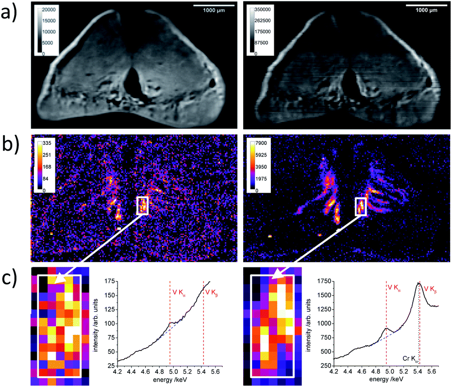 | ||
| Fig. 6 μXRF measurements on a cross section of a mussel foot. Please note the different intensity legends. Left: measurement with the M4 Tornado at 50 W. Right: measurement conducted with LMJS and optimized polycapillary lens at 250 W. (a) and (b) show the net peak intensity distribution of K K lines and V K lines respectively. (c) shows a detail of the V K lines distribution and a summed spectrum over 80 pixels of the approximately equal region on the mussel foot cross section containing vanadium. The color bars give the measured intensities in counts per second (CPS) per steradian (sr) of the fluorescence signal. The spectra are normalized to the life time and the solid angle of detection. | ||
The excitation efficiency for the V K fluorescence is increased for the LMJS setup due to the higher power and better adapted energy of the characteristic radiation (V Kab = 5.46 keV, Ga Kα 9.25 keV, Rh Kα = 20.22 keV) – resulting in roughly 24 times higher net peak intensities for the measurement with the LMJS at 250 W. Considering the same excitation power (50 W) for both setups the factor would be roughly 5. The ratio is calculated by dividing the mean net peak intensity of the ten maximal pixels of the LMJS measurement by the same value derived from the M4 Tornado measurement. Accordingly, the net peak intensities of the P K, S K, Cl K and K K fluorescence lines are also increased. Additionally, the calculations were made for the five and twenty maximum pixels, resulting in the same ratios. The ratios are given in Table 4 and the additional element distributions are shown in the ESI (Fig. S4†). In case of Br K lines, which lie energetically higher than the characteristic Ga K lines, the measured net peak intensities are only increased by a factor of 3 compared to the measurement with the M4 Tornado, which is solely caused by the higher power of the LMJS.22 In the M4 Tornado measurement, areas enriched with vanadium are assumable, but in the measurement with the LMJS setup structures are visible very clearly in the V K lines signal. This signal is related to longitudinal ducts in the mussel foot.20 Due to excitation intensity fluctuations caused by temperature variations during the measurement, the element distributions measured with the LMJS setup needed to be corrected using the scattered signal. Detailed information about the correction procedure is given in the ESI (Section S5†). In Fig. 6c a detail of the measurement is shown and the summed spectra of 80 pixels of an area which contains vanadium are depicted for both measurements. The Cr Kα peak in the spectra obtained by the LMJS setup is a background signal from the measurement chamber.
| Fluorescence lines | P K | S K | Cl K | K K | V K | Br K |
|---|---|---|---|---|---|---|
| Absorption edge energy/keV | 2.15 | 2.47 | 2.83 | 3.61 | 5.46 | 13.47 |
| Net peak intensity ratio LMJS/M4 Tornado | 6 | 10 | 15 | 22 | 24 | 3 |
Conclusions
We characterized the effective transmission and exit focal spot size of four different types of polycapillary lenses in combination with a LMJS for the use in laboratory μXRF setups. The investigation of four different types of lenses demonstrates possibilities and constraints by adapting the parameters of the polycapillary lenses to fit the source parameters best, e.g. source spot size and source-to-polycapillary distance, and the measurement needs, e.g. source to sample distance, excitation power and desired resolution.The lens which was especially designed for the LMJS shows the best effective transmission in combination with a relatively small exit focal spot size of (22 ± 5) μm for Fe K radiation. This is realized i.a. by an entrance focal distance which is as small as geometrically possible and a designed maximal transmission for the Ga K fluorescence line energies, enabling an efficient collection of the radiation originating from the small source spot of the LMJS.
The source spot size of the LMJS was changed to investigate the influence of the small effective source spot size of these novel laboratory X-ray sources. The effective transmission is affected by increasing the source spot size when the field of view of the polycapillary lens is small, since then the source spot size rapidly exceeds the spot from which radiation can be collected by the polycapillary lens. The field of view is mainly determined by the entrance focal distance.13 As a result, the effective transmission of the optimized lens with the smallest entrance focal distance (32 mm) decreases as soon as the height of the source spot size is increased. On the contrary, for the SEM like lens, which has a much bigger field of view, there is no significant decrease of the effective transmission seen by changing the source height from 25 μm to 100 μm.
We also performed knife edge scans on a razor blade with a varying source spot size, but the exit focal spot size is only defined by the second half of the lens and is therefore largely independent from the source spot size.
The measurements using different types of polycapillary lenses in combination with the variation of source spot size showed on the one hand, that a special adaption of polycapillary lenses to a small effective source spot size is possible. Additionally, the combination of LMJS and different polycapillary lenses gives a wide scope in terms of optimizing the needed resolution and the greatest producible field of view of the lens, so that the lens could be combined with a bigger source spot size and resulting higher possible electron beam power.
We used the μXRF setup with LMJS and optimized polycapillary lens (A) to investigate the effect of the optimized excitation efficiency of the measurement of vanadium traces in a mussel foot sample. The values of the measured vanadium net peak intensities are increased by a factor of 24 compared to the measurement using the state-of-the-art setup. The factor varies for other transition metals from roughly 20 for Sc K fluorescence to 50 for Cu K fluorescence. Thus, the combination of well adapted polycapillary lenses and the LMJS yield significant advantages in the excitation of traces of transition metals e.g. in biological samples.
Author contributions
Leona J. Bauer: conceptualization, formal analysis, investigation, writing – original draft, validation. Richard Gnewkow: conceptualization, software, writing – review & editing. Frank Förste: data curation, investigation, software. Daniel Grötzsch: methodology, resources. Semfira Bjeoumikhova: conceptualization, resources. Birgit Kanngießer: resources, supervision, validation, writing – review & editing. Ioanna Mantouvalou: conceptualization, project administration, supervision, validation, writing – review & editing.Conflicts of interest
There are no conflicts to declare.Acknowledgements
We thank Serena de Beer for providing the LMJS, Excillum Inc. for technical support with the LMJS and Helmut Fischer GmbH for providing the polycapillary lenses. We thank Matthew Harrington and Tobias Priemel for the provision of the mussel foot cross section.References
- T. Lachmann, G. Van Der Snickt, M. Haschke and I. Mantouvalou, J. Anal. At. Spectrom., 2016, 31, 1989–1997 RSC.
- B. De Samber, G. Silversmit, K. De Schamphelaere, R. Evens, T. Schoonjans, B. Vekemans, C. Janssen, B. Masschaele, L. Van Hoorebeke, I. Szalóki, F. Vanhaecke, K. Rickers, G. Falkenberg and L. Vincze, J. Anal. At. Spectrom., 2010, 25, 544–553 RSC.
- B. Kanngießer, I. Mantouvalou, W. Malzer, T. Wolff and O. Hahn, J. Anal. At. Spectrom., 2008, 23, 814–819 RSC.
- L. J. Bauer, H. A. Mustafa, P. Zaslansky and I. Mantouvalou, Acta Biomater., 2020, 109, 142–152 CrossRef CAS PubMed.
- M. A. Denecke, K. Janssens, K. Proost, J. Rothe and U. Noseck, Environ. Sci. Technol., 2005, 39, 2049–2058 CrossRef CAS PubMed.
- V. Arkadiev and A. Bjeoumikhov, in Handbook of Practical X-Ray Fluorescence Analysis, ed. B. Beckhoff, B. Kanngießer, N. Langhoff, R. Wedell and H. Wolff, Springer, 2006 Search PubMed.
- C. Seim, C. Laurenze-Landsberg, B. Schröder-Smeibidl, I. Mantouvalou, C. De Boer and B. Kanngießer, J. Anal. At. Spectrom., 2014, 29, 1354–1360 RSC.
- K. G. McIntosh, N. L. Cordes, B. M. Patterson and G. J. Havrilla, J. Anal. At. Spectrom., 2015, 30, 1511–1517 RSC.
- X. Wei, Y. Lei, T. Sun, X. Lin, Q. Xu, D. Chen, Y. Zou, Z. Jiang, Y. Huang, X. Yu, X. Ding and H. Xu, X-Ray Spectrom., 2008, 37, 595–598 CrossRef CAS.
- A. R. Woll, J. Mass, C. Bisulca, R. Huang, D. H. Bilderback, S. Gruner and N. Gao, Appl. Phys. A: Mater. Sci. Process., 2006, 83, 235–238 CrossRef CAS.
- I. Mantouvalou, T. Wolff, C. Seim, V. Stoytschew, W. Malzer and B. Kanngiesser, Anal. Chem., 2014, 86, 9774–9780 CrossRef CAS PubMed.
- T. Sun and X. Ding, J. Appl. Phys., 2005, 97, 124904 CrossRef.
- A. Bjeoumikhov, S. Bjeoumikhova and R. Wedell, Part. Part. Syst. Charact., 2005, 22, 384–390 CrossRef.
- M. Haschke and M. Haller, X-Ray Spectrom., 2003, 32, 239–247 CrossRef CAS.
- L. Bauer, M. Lindqvist, F. Förste, U. Lundström, B. Hansson, M. Thiel, S. Bjeoumikhova, D. Grötzsch, W. Malzer, B. Kanngießer and I. Mantouvalou, J. Anal. At. Spectrom., 2018, 33, 1552–1558 RSC.
- M. Otendal, T. Tuohimaa, U. Vogt and H. M. Hertz, Rev. Sci. Instrum., 2008, 79, 16–19 CrossRef PubMed.
- rtw RÖNTGEN-TECHNIK DR. WARRIKHOFF GmbH & Co. KG, cited 2021 July 7, https://www.rtwxray.de/pdf/footer/brochure.pdf.
- E. Metwalli, K. Götz, S. Lages, C. Bär, T. Zech, D. M. Noll, I. Schuldes, T. Schindler, A. Prihoda, H. Lang, J. Grasser, M. Jacques, L. Didier, A. Cyril, A. Martel, L. Porcar and T. Unruh, J. Appl. Crystallogr., 2020, 53, 722–733 CrossRef CAS PubMed.
- T. Wolff, I. Mantouvalou, W. Malzer, J. Nissen, D. Berger, I. Zizak, D. Sokaras, A. Karydas, N. Grlj, P. Pelicon, R. Schütz, M. Žitnik and B. Kanngießer, J. Anal. At. Spectrom., 2009, 24, 669–675 RSC.
- T. Priemel, G. Palia, F. Förste, F. Jehle, S. Sviben, I. Mantouvalou, P. Zaslansky, L. Bertinetti and M. J. Harrington, Science, 2021, 374, 206–211 Search PubMed.
- T. Wolff, BAM Bundesanstalt für Materialforschung und -prüfung, 2009 Search PubMed.
- A. Brunetti, M. Sanchez Del Rio, B. Golosio, A. Simionovici and A. Somogyi, Spectrochim. Acta, Part B, 2004, 59, 1725–1731 CrossRef.
- J. Sherman, Spectrochim. Acta, 1995, 7, 283–306 CrossRef.
- W. T. Elam, B. D. Ravel and J. R. Sieber, Radiat. Phys. Chem., 2002, 63, 121–128 CrossRef CAS.
Footnote |
| † Electronic supplementary information (ESI) available: Details about the LMJS, determination of Gumbel function, exit focal spot size by varying source spot size, additional elemental images and correction procedure. See DOI: 10.1039/d1ja00295c |
| This journal is © The Royal Society of Chemistry 2021 |