
A feasibility study on the application of separable coded masks to X-ray fluorescence imaging
Shifeng
Sun
 *a and
Xiaoping
Ouyang
b
*a and
Xiaoping
Ouyang
b
aSchool of Nuclear Science and Engineering, North China Electric Power University, Beijing 102206, P. R. China. E-mail: sunshf@ncepu.edu.cn
bState Key Laboratory of Intense Pulse Radiation Simulation and Effect, Northwest Institute of Nuclear Technology, Xi'an, 710024, P. R. China
First published on 21st November 2020
Abstract
For every imaging method, optics plays a vital role. Compared to polycapillary optics or a pinhole-collimator, the use of coded apertures as X-ray optics has the advantages of simple fabrication, high sensitivity, and scalability. Therefore, this work explores the feasibility of applying the coded aperture method to X-ray fluorescence imaging. The proposed imaging system consists of a 2D position-sensitive detector coupled to a 2D multi-hole mask, which is parallel and center-aligned to the detector. To reduce the complexity of system calibration and image reconstruction, a separable mask design and a novel near-field coded aperture imaging model were adapted. The performance of the system was investigated using the Geant4 Monte Carlo simulations. Image reconstruction was performed with the iterative algorithm and the deep learning neural network. High quality 2D and 3D images of complex shaped objects can be reconstructed from a single recorded coded image. Unlike imaging systems based on the conventional convolution model, this system can maintain high spatial resolution over a considerable distance range. For the object-to-mask distances of 8 mm and 26 mm, the spatial resolution is 23.7 μm and 36.2 μm, respectively. The 3D reconstruction results show that the system is able to correctly estimate the object-to-mask distance with an axial spatial resolution of 0.75 mm.
1. Introduction
X-ray fluorescence (XRF) techniques are powerful tools for nondestructive elemental analysis of various samples and have been extensively used in many fields, such as materials sciences, environmental sciences, biological sciences, and industry.1–3 In many analytical applications, to spatially resolve elemental distributions in samples, XRF imaging techniques capable of elemental mapping/imaging are required. Generally, the well-established scanning micro-XRF methods are used to perform 2D elemental imaging.4 The main drawback of these methods is the long acquisition time.In addition to scanning methods, 2D images can also be obtained by using suitable optics and 2D detectors. In analogy to visible light imaging, the quality of an X-ray image largely depends on the performance of the optics. Polycapillary optics based on total external reflection have been developed, but their throughput is limited by the small acceptance angle of capillaries, which affects the count rate.5 Meanwhile, these advanced X-ray optics based on reflective focusing have to fulfill very high requirements and can be very expensive.6–8
A simpler imaging method is to use a pinhole to collimate X-rays without focusing. For a pinhole camera, the spatial resolution of the system depends largely on the pinhole size. To achieve an acceptable resolution, a small aperture is required, but at the same time, a small aperture will result in low photon throughput.9 One solution to improve the throughput is to use a multiple-pinhole mask, the so-called coded aperture. The coded aperture technique greatly increases the photon flux by N (the number of pinholes) times, while retaining the high spatial resolution corresponding to the small aperture, thereby improving the signal-to-noise ratio (SNR) of the image.10,11
Compared with X-ray focusing optics, the coded aperture approach has the advantage of low cost, easy to use, and high numerical aperture.5 Unlike focusing cameras, which directly record a scaled image of the object, the detector measurements of a coded aperture camera are a superposition of the images formed due to each pinhole, and therefore, a computational image reconstruction procedure is necessary.12 Haboub et al. explored the use of the coded aperture technique for XRF imaging, and obtained images of several samples experimentally, which initially verified the feasibility of the technique.13,14 Kulow et al. further studied the image reconstruction algorithms for near-field coded aperture imaging and proved through experiments that the use of coded aperture optics can significantly increase the count rate and reduce the acquisition time.15
Currently, XRF imaging with coded aperture optics has shown great potential, yet there are still some issues to resolve, including low spatial resolution and near-field artifacts. The spatial resolution could be improved by reducing the size of the hole, but this will make image reconstruction very difficult and increase image artifacts. To obtain acceptable results, the advanced iterative algorithm is needed to reconstruct images. However, for an object of 235 × 235 pixels, the required computer memory was already about 238 GB and one reconstruction had already taken 40 minutes.15 The computer memory was mainly used to load a projection function matrix that represents the linear relationship between the object and the detector measurements. For an object of M × M pixels and a detector of N × N pixels, the projection function matrix is an M2 × N2 matrix. When the desired spatial resolution is higher, the object will be divided into more pixels, and the projection function matrix will become too large to estimate or invert (image reconstruction). Moreover, in related studies, the diameter of the hole is generally tens of microns, and the spatial resolution achieved is also tens of microns.13–15 Therefore, to achieve a spatial resolution of several microns, the diameter of the holes needs to be only several microns. However, since the aperture thickness is generally tens of microns (to block X-rays), reducing the diameter of the holes from tens of microns to several microns will greatly reduce the diameter-to-thickness ratio of the holes and enhance the aperture collimation effects, thereby increasing the image artifacts.12
In recent years, remarkable progress has been made in visible-light lensless coded aperture imaging. DeWeert and Asif proposed to use a separable mask pattern, which drastically reduces the storage and computational burden of the projection function matrix, and realized high-resolution visible-light coded aperture imaging.16,17 Based on the separable mask design, Adams and Boominathan further proposed a novel near-field coded aperture imaging model called Texas Two-Step (T2S), which decomposes the detector measurements as a superposition of two separable functions, and realized near-field high-resolution 3D visible-light imaging.18 The T2S model has been shown to be applicable for near-field high-resolution gamma-ray and X-ray imaging.19,20
The existing method formulates the computational image reconstruction problem as regularized least-squares minimization and uses an iterative algorithm. However, as the coded aperture design generally results in an ill-conditioned system and the poor design of the image reconstruction algorithm may lead to serious noise amplification, the existing method suffers from various drawbacks including low resolution and high noise sensitivity.21 Recently, deep learning-based methods have shown remarkable performance in image processing applications and have been successfully applied to image reconstruction.22,23 These learning-based methods use data-driven techniques to improve reconstruction performance by exploiting the structure within the data.
The development of the novel coded aperture imaging model and image reconstruction methods may bring a better solution for coded aperture XRF imaging. With this in mind, we studied the feasibility of applying the separable mask based T2S model and deep learning methods to high-resolution XRF imaging. To fully investigate the potential performance of the coded aperture design, an X-ray imaging system based on a separable mask and a 2D detector was modeled by Monte Carlo simulation to simulate the X-ray imaging process and obtain data for calibration, training, and imaging. The reconstruction with an iterative algorithm and the convolutional neural network was compared by two metrics.
2. Methods
2.1. Imaging model
The principle of X-ray fluorescence imaging with coded aperture optics is depicted in Fig. 1. The sample is irradiated by X-rays from X-ray tubes or a synchrotron to produce fluorescence. The fluorescent X-rays emitted from the object in the sample are modulated by the 2D coded aperture mask and then recorded on the 2D position-sensitive detector. The multi-hole mask consists of opaque and transparent elements that either block or transmit X-rays. The mask is placed parallel to the detector with an adjustable distance. The principle of coded aperture imaging for XRF imaging is described in more detail in ref. 13 and 14.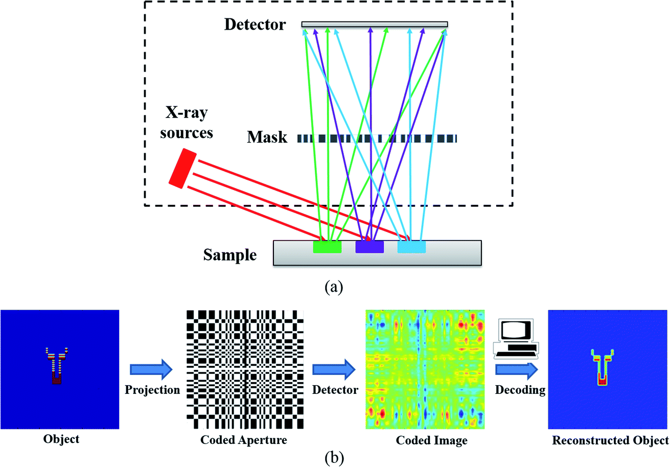 | ||
| Fig. 1 (a) Schematic illustration of the X-ray fluorescence imaging with coded aperture optics. (b) The principle of coded aperture imaging. The photons emitted from the object pass through the transparent elements of the mask and are projected onto the detector. The object image can be obtained using suitable reconstruction methods. | ||
In the T2S model, for a 2D planar object X at a certain distance from the mask plane, the detector measurements Y satisfy21
| Y = PoXQTo + PcXQTc | (1) |
For a 3D object XD, which can be discretized as a superposition of planar objects Xd at D different distances (d) from the mask, the detector measurements Y satisfy
 | (2) |
2.2. Simulation setup
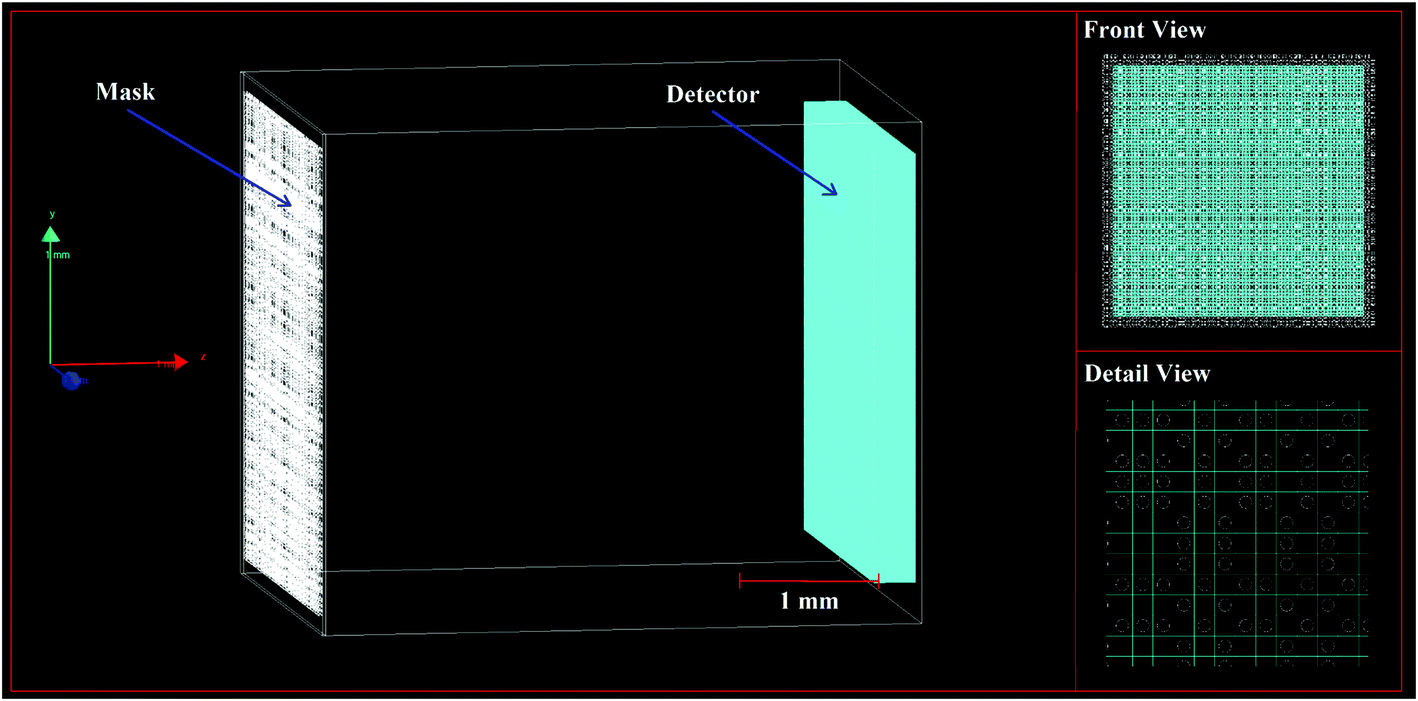
Monte Carlo simulation plays an important role in many fields including radiation detector design and imaging system studies.24,25 Geant4 is a general-purpose Monte Carlo simulation toolkit developed to simulate particle transportation in matter, and it has been widely used and supported in radiation detection and imaging.24 Geant4 version 10.04.p01 with the reference physics list QGSP_BIC_EMZ was used to simulate X-ray imaging. The range cut-off for all particles was set to be 0.1 mm.The geometry of the XRF imaging system is shown in Fig. 2. The system consists of a multi-hole mask placed in front of a 2D position-sensitive detector. The volume of the Si detector employed in the system was set to 3.072 × 3.072 × 0.3 mm3, divided into 256 × 256 pixels, with a pixel size of 12.0 μm × 12.0 μm. The detector was modeled with reference to the INTPIX6 SOI pixel detector.26 Considering that Monte Carlo simulation is very time-consuming, the detector was not set to have more pixels. In all simulations, the detector was set as an energy dispersive detector, which means that each pixel of the detector recorded a whole spectrum. For simplicity, the energy resolution of the detector was set to a fixed value of 1 keV. For an energy range of 1–20 keV, the energy spectrum was divided into 20 channels. For example, when the energy deposited by the incident photon in the detector was between 9.5 and 10.5 keV, the count corresponding to the 10th channel in the energy spectrum increased by one. Since the energy resolution of a real energy dispersive detector is generally better than that of the simulated detector, the above simplification does not lead to experimental impossibility.
 | ||
| Fig. 2 Global geometric structure of the imaging system. | ||
The mask had 39![[thin space (1/6-em)]](https://www.rsc.org/images/entities/char_2009.gif) 200 holes with a diameter of 7.2 μm arranged as a pre-defined pattern in 24.0 μm thick platinum foil. To make the mask self-supporting, the spacing between the holes was set to 12.0 μm, which was slightly less than twice the diameter of the holes. The mask pattern was designed by selecting 280 × 280 pixels in the central part of a rank 911 modified uniformly redundant arrays.27 The number 911 was chosen because it is a large prime number. The active area of the mask was 3.36 × 3.36 mm2, which was slightly larger than that of the detector. The holes had a circular shape, and the area of all holes accounts for 14.1% of the total area of the mask. The object-to-mask distance (d1) was adjustable, and the mask-to-detector distance (d2) was set to a fixed value of 4.0 mm.
200 holes with a diameter of 7.2 μm arranged as a pre-defined pattern in 24.0 μm thick platinum foil. To make the mask self-supporting, the spacing between the holes was set to 12.0 μm, which was slightly less than twice the diameter of the holes. The mask pattern was designed by selecting 280 × 280 pixels in the central part of a rank 911 modified uniformly redundant arrays.27 The number 911 was chosen because it is a large prime number. The active area of the mask was 3.36 × 3.36 mm2, which was slightly larger than that of the detector. The holes had a circular shape, and the area of all holes accounts for 14.1% of the total area of the mask. The object-to-mask distance (d1) was adjustable, and the mask-to-detector distance (d2) was set to a fixed value of 4.0 mm.
2.3. Reconstruction methods
 | (3) |
![[X with combining circumflex]](https://www.rsc.org/images/entities/i_char_0058_0302.gif) D is the estimated object image. In this work, the above problem was solved using the fast iterative shrinkage–thresholding algorithm (FISTA).28 In a close object-to-mask distance range, both 2D and 3D images can be reconstructed from a single detector measurement.
D is the estimated object image. In this work, the above problem was solved using the fast iterative shrinkage–thresholding algorithm (FISTA).28 In a close object-to-mask distance range, both 2D and 3D images can be reconstructed from a single detector measurement.
As image reconstruction requires the transfer matrices to be known, a calibration procedure is needed to estimate the transfer matrices. For the proposed system, calibration was performed by translating a 3.072 mm long line source (emitting single energy X-rays) to the required object-to-mask distance and then scanning the FOV along the x-axis and y-axis. If the energy recorded by a pixel of the detector was equal to the energy of the incident photons, the corresponding pixel number was recorded to form the mask projections. And then the transfer matrices of a certain object-to-mask distance can be obtained using a truncated singular value decomposition (SVD) of the mask projections. As the transfer functions are dependent on the energy of the incident photons, the system was calibrated for different energies of line sources (5, 10, 15, and 20 keV) independently. These energies were selected within the hard X-ray range (5–20 keV).
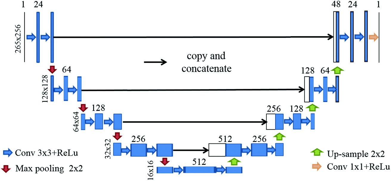 | ||
| Fig. 3 The U-net architecture for reconstructing images from the original recorded coded images. The sizes of all blocks are shown in the figure. Each arrow represents an operation. | ||
The training and testing data for the network were produced by simulating the X-ray imaging process of different objects. Each object consists of six randomly distributed rectangles and annuluses of different sizes and intensities. The length and width of the rectangles were in the range of 12 to 300 μm; the radius and inner-radius of the annuluses were in the range of 12 to 180 μm and 24 to 360 μm, respectively. All the training and testing images were obtained by placing the objects (energy 10 keV) at an object-to-mask distance of 12.00 mm. The number of photons simulated for each object was 4 × 10¹⁰; both the coded images and the ground truth images were saved. Fig. 4 demonstrates two examples in the dataset. The number of images in the training and validation sets was 19000 and 1000, respectively.
 | ||
| Fig. 4 Two examples in the dataset. (a) The ground truth of example 1. (b) The recorded coded image of example 1. (c) The ground truth of example 2. (d) The recorded coded image of example 2. | ||
Using the training data, the network was trained by minimizing the loss function defined as the mean square error (MSE) between the predicted images and the ground truth images. An Adam optimizer was used with β1 = 0.9 and β2 = 0.999. The learning rate was set to 10−3 and was halved every 40 iterations. The batch size and the number of epochs were set to 5 and 200, respectively. The neural network was implemented in PyTorch and the trainings ran on an NVIDIA GTX 1080 GPU.
2.4. Quantitative analysis
To test the imaging performance of the system, a series of simulations were performed with two test objects. These objects were all planar sources placed on a plane parallel to the mask. The first test object (Fig. 5a) consists of four letters, each consisting of two lines or an annulus. The length of the line was 0.6 mm or 0.4 mm, and the width was 0.001 mm; the radius of the annulus was 0.3 mm and the inner radius was 0.299 mm. This object was used to demonstrate the ability of the system to image complex objects. The second test object (Fig. 5b) was a rectangle with a length of 0.6 mm and a width of 0.2 mm, and it was used to estimate the spatial resolution of the system. The spatial resolution was determined by analyzing the edge spread function (ESF) obtained from the sharp-edge of the test object.9 The original ESF curve was calculated by averaging pixel values of the reconstructed image in the lines parallel to the object edge. The ESF was fitted with a sigmoidal function and was then differentiated to obtain the Line Spread Function (LSF).30,31 The full width at half maximum (FWHM) of the LSF was defined as the spatial resolution. | ||
| Fig. 5 Original images of two objects. (a) The first test object. (b) The second test object. | ||
The reconstruct images under different conditions were quantified and compared using two standard metrics, the Root Mean Square Error (RMSE) and Universal Image Quality Index (UQI).32 The RMSE is defined as:
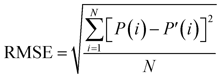 | (4) |
UQI is defined as:
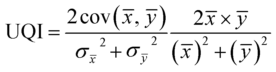 | (5) |
![[x with combining macron]](https://www.rsc.org/images/entities/i_char_0078_0304.gif) and ȳ are the means and
and ȳ are the means and  and
and  the variances of the original object image and reconstructed image, respectively. The maximum and minimum values of UQI are 1 and 0, respectively. The higher the UQI, the less the distortion.
3. Results and discussion
3.1. Counts
Compared to a small diameter pinhole, the main advantage of the proposed mask is the higher throughput. To demonstrate this, we compared the recorded counts of the pinhole systems and the coded aperture system under the same conditions. The pinhole systems were constructed simply by replacing the mask in the coded aperture system with a pinhole-collimator of different diameters; other parameters of the pinhole systems are the same as those of the coded aperture system for making a fair comparison. The material and thickness of the pinhole-collimators are the same as those of the mask; the diameter of the pinholes varies from 7.2 μm to 1440 μm.A point source (energy 5 keV) was placed at the center of the FOV with an object-to-system distance of 12 mm and a total of 4 × 10¹⁰ photons was simulated for each system. The corresponding recorded counts are shown in Fig. 6. As the pinhole diameter increases, the recorded counts increase approximately proportional to the square of the pinhole diameter. The recorded counts of the mask are approximately the same as those of a pinhole with a diameter of 809 μm. However, for an 809 μm pinhole, the spatial resolution is in the order of a few hundred microns.
 | ||
| Fig. 6 Comparison between the recorded counts of the pinhole systems and the coded aperture system. The total opening area of the mask is approximately equal to a pinhole with a diameter of 1426 microns. | ||
3.2. Reconstruction with the iterative algorithm
 | ||
| Fig. 7 Reconstructed images of the first test object at different object-to-mask distances. (a) At 8.00 mm. (b) At 26.00 mm. | ||
 | ||
| Fig. 8 Reconstructed images and LSF functions of the second test object at different object-to-mask distances. (a) Reconstructed images at 8.00 mm. (b) LSF functions at 8.00 mm. (c) Reconstructed images at 26.00 mm. (d) LSF functions at 26.00 mm. | ||
The spatial resolution of the system increases slightly with the increase of the object-to-mask distance (see Fig. 9). The value indicated for each of the object-to-mask distance in Fig. 9 was determined by averaging the FWHM obtained by analyzing the edge profile of the second test object. For a system based on the conventional convolution model, the spatial resolution increases approximately proportionally with the increase of the object-to-mask distance.14 However, the proposed system can maintain high spatial resolution over a significant distance range.
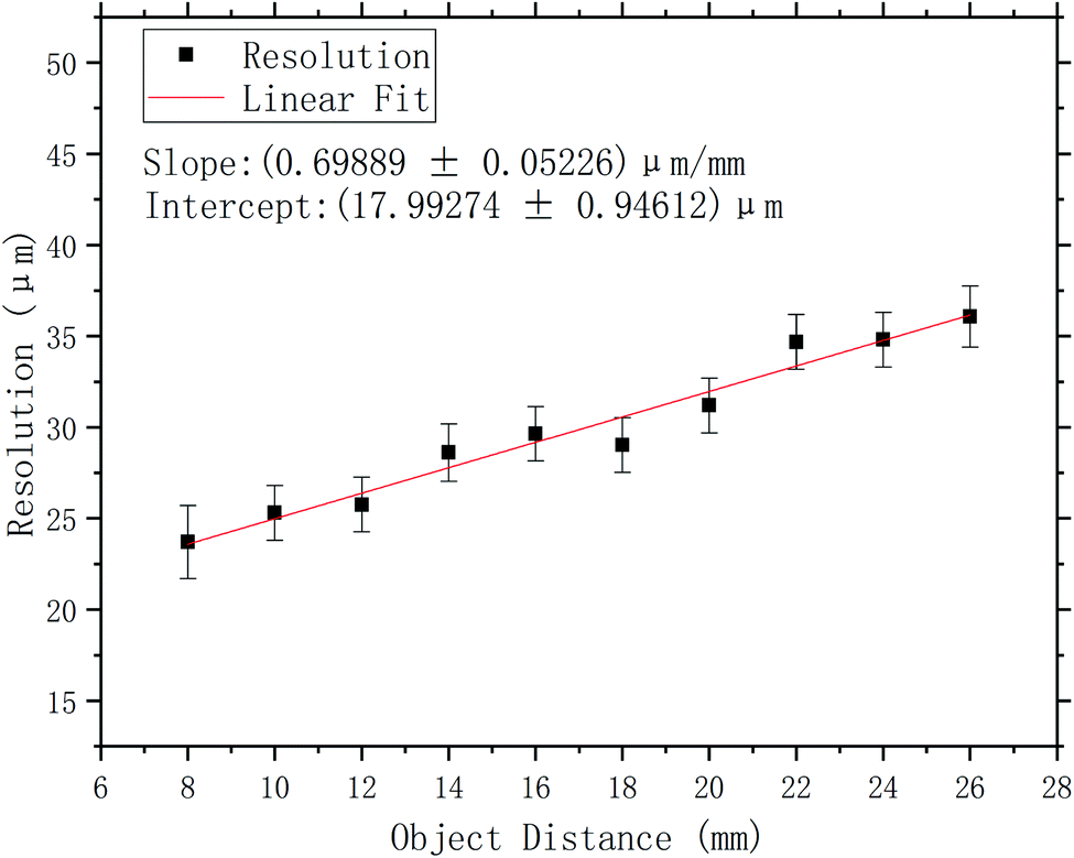 | ||
| Fig. 9 The spatial resolution of the system varies with the object-to-mask distance. | ||
 | ||
| Fig. 10 2D slices in the XY plane from Z = 11.00 mm to Z = 13.00 mm of the 3D reconstructed image of the first test object. | ||
To further demonstrate the 3D image reconstruction ability of the system, we divided the first test object into four letters, ‘L’, ‘O’, ‘T’, and ‘O’, and placed them at different object-to-mask distances from the mask. The letter ‘L’ is at the closest distance from the mask, at 12.00 mm; the other three letters,‘O’, ‘T’, and ‘O’ are at 13.00 mm, 14.00 mm, and 15.00 mm from the mask, respectively. As shown in Fig. 11, the distribution of the four letters in the three-dimensional space can be accurately reconstructed from a single image capture. This is an important advantage of the T2S model over the conventional convolution model, which usually can only reconstruct 2D images.
 | ||
| Fig. 11 3D reconstructed image of the four letters. | ||
When the calibration energy is 5 keV, the reconstructed image corresponding to an object energy of 5 keV is of the best quality (see Fig. 12); as the energy of the first test object increases from 10 keV to 20 keV, the noise in the reconstructed images gradually increases. When the calibration energy is 20 keV, the reconstructed image corresponding to the object energy of 5 keV shows noise and distortion (see Fig. 13); the quality of the reconstructed images is better when the object energies are 10, 15, and 20 keV. Fig. 14 shows how the quantitative assessment parameters of the reconstructed image of the first test object vary with the object energy and the calibration energy. For different object energies, the optimal values of the quantitative assessment parameters of the reconstructed image corresponding to different calibration energies are close, all appearing in the case where the calibration energy and the object energy are the same. When the calibration energy is different from the object energy, the quality of the reconstructed image will decrease; the larger the difference between these two energies, the poorer the quality of the reconstructed image. Overall, the quality of the reconstructed image is less affected by the change of the object energy when the calibration energy is 10 keV. In order to obtain high quality reconstructed images corresponding to a certain energy, it is preferable to calibrate the system with that energy.
 | ||
| Fig. 12 Reconstructed images of the first test object with different energies at a calibration energy of 5 keV. | ||
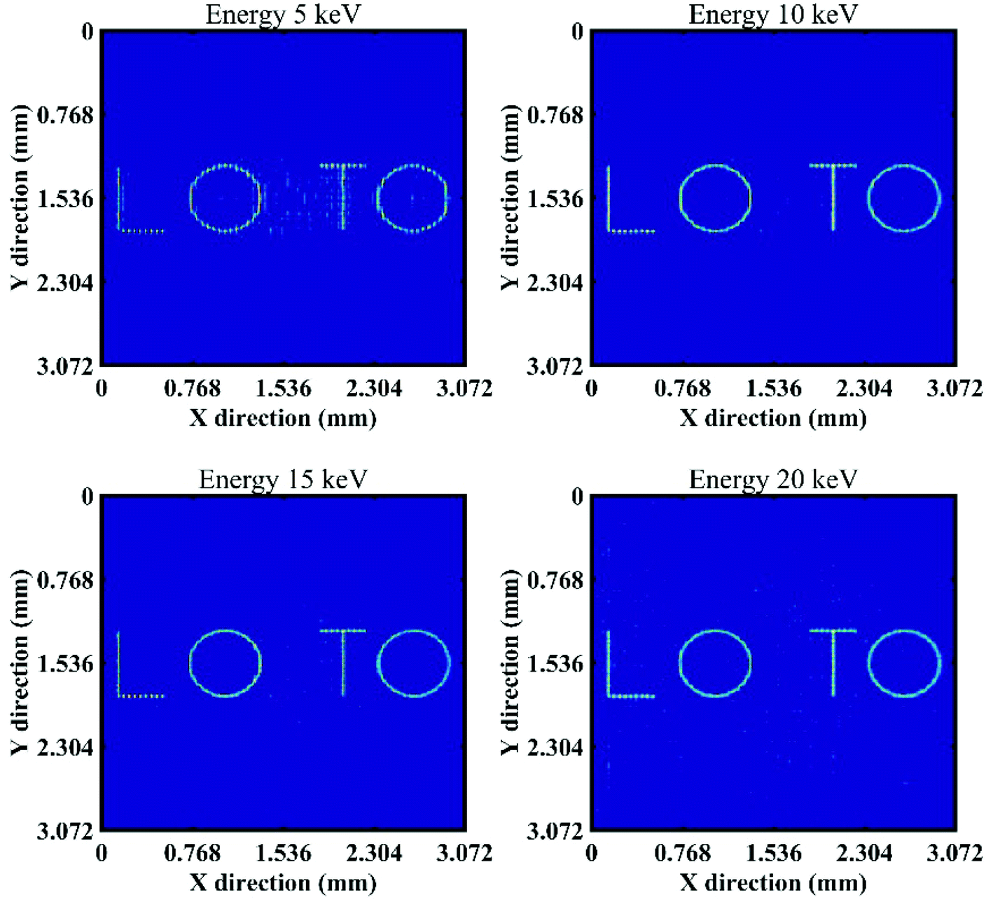 | ||
| Fig. 13 Reconstructed images of the first test object with different energies at a calibration energy of 20 keV. | ||
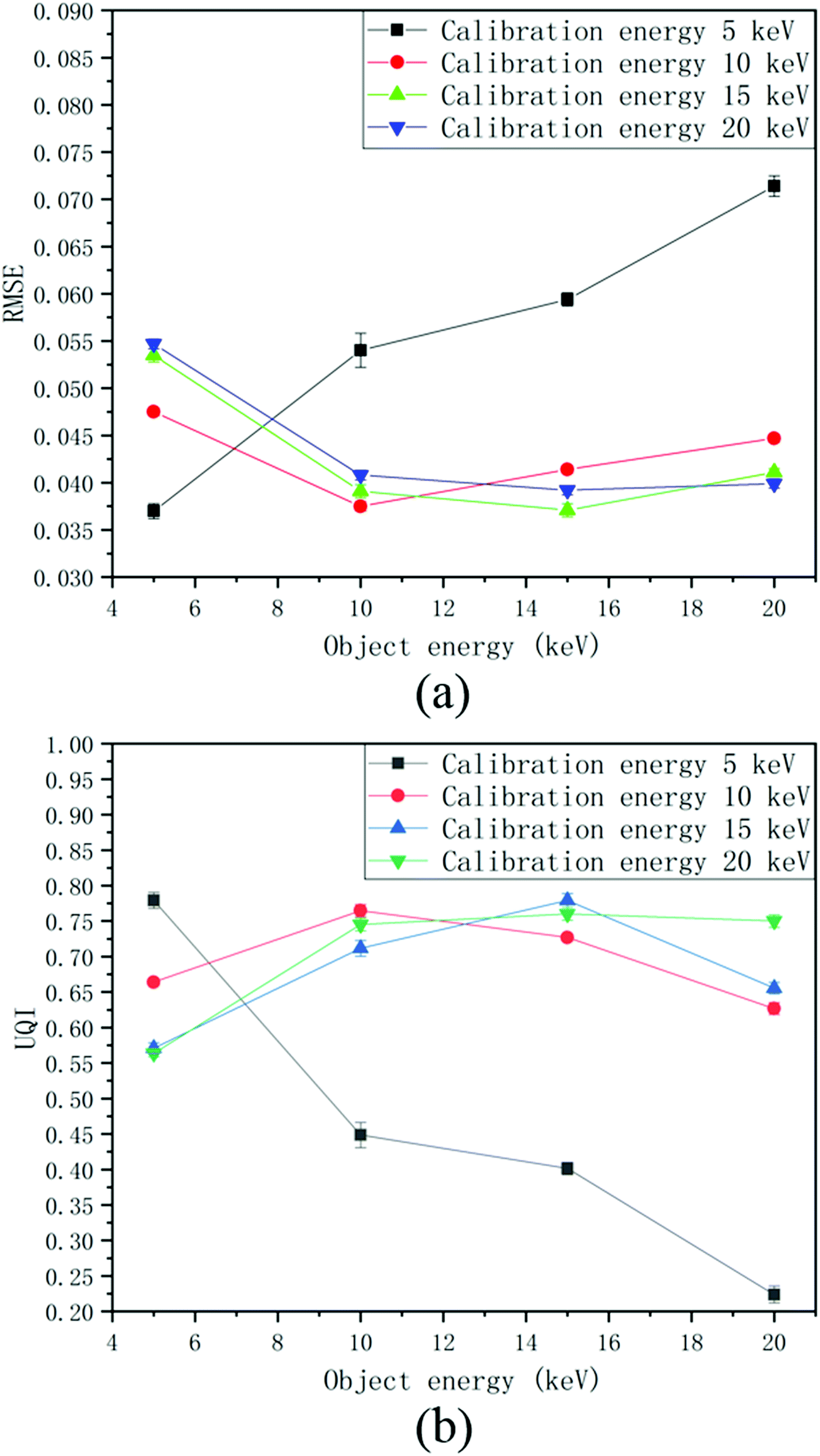 | ||
| Fig. 14 Comparison of the reconstructed images with different calibration energies and object energies using two assessment parameters. (a) RMSE; (b) UQI. | ||
3.3. Reconstruction with the deep learning neural network
After the training of U-Net, image reconstruction can be performed very fast for each recorded coded image. We randomly generated 10 new samples to evaluate the performance of the trained network. As shown in Fig. 15, the neural network is able to reconstruct the sample images, but may not be able to recover some details, such as the topmost annulus of sample 1 and the rightmost rectangle of sample 3. For sample 2, the neural network cannot reconstruct the left bottom rectangle when the rectangle and annulus overlap. Visually, the reconstructed images of the neural network are less noisy and smoother than those of the iterative algorithm. However, the comparison of the quantitative assessment parameters shows that the quality of the reconstructed images of the neural network is slightly worse than that of the iterative algorithm (see Fig. 16). | ||
| Fig. 15 Comparison of reconstructions, the first through fourth rows correspond to sample 1 through 4, respectively. The first column: the ground truth of samples; the second column: the original recorded coded images; the third column: reconstruction with the neural network (U-Net); the fourth column: reconstruction with the iterative algorithm. | ||
 | ||
| Fig. 16 Comparison of the reconstructed images of the iterative algorithm and neural network using two assessment parameters. (a) RMSE; (b) UQI. | ||
For the first test object (energy 10 keV) at an object-to-mask distance of 12 mm, the neural network cannot reconstruct the image of the object correctly. This is mainly due to the fact that the first test object differs greatly from the training images. This may imply that a purely deep learning-based method does not have convergence guarantees compared to the iterative method. Better reconstructed images may be obtained if the deep learning-based approach can incorporate the physics knowledge of the imaging system.
4. Conclusion
The feasibility of developing a novel coded aperture imaging system for high-spatial resolution X-ray fluorescence imaging has been investigated in this study. The proposed system consists of a 2D multi-hole mask placed in front of a 2D position-sensitive detector. The original recorded coded images of the objects were reconstructed with the FISTA algorithm and the U-Net neural network. The results of simulations show that high quality 2D and 3D images of different test objects can be reconstructed from a single image capture. Unlike conventional coded aperture systems based on the convolutional model, this system can maintain high spatial resolution over a considerable distance range. As the object-to-mask distance increased from 8 mm to 26 mm, the spatial resolution of the system changed from 23.7 μm to 36.2 μm. The quality of the reconstructed image was affected by both the energy of the object and the calibration energy; the smaller the difference between the two, the higher the quality of the reconstructed image. Overall, the quality of the reconstructed image of the iterative algorithm was slightly better than that of the neural network. Future work will focus on optimizing system design and developing new deep learning-based algorithms that incorporate knowledge of physical systems to improve the quality of reconstructed images and the spatial resolution of the system. In addition, we will experimentally validate the separable coded mask design and compare the simulation results with the experimental results.Conflicts of interest
There are no conflicts to declare.Acknowledgements
This work was supported by the National Natural Science Foundation of China (Grant No. 11805066) and the fund of the Nuclear Power Technology Innovation Centre (Grant No. HDLCXZX-2020-HD-018).References
- R. Terzano, M. A. Denecke, G. Falkenberg, B. Miller, D. Paterson and K. Janssens, Pure Appl. Chem., 2019, 91, 1029–1063 CAS.
- M. Rauwolf, A. Turyanskaya, A. Roschger, J. Prost, R. Simon, O. Scharf, M. Radtke, T. Schoonjans, A. Guilherme Buzanich, K. Klaushofer, P. Wobrauschek, J. G. Hofstaetter, P. Roschger and C. Streli, J. Synchrotron Radiat., 2017, 24, 307–311 CrossRef CAS.
- J. D. Grunwaldt and C. G. Schroer, Chem. Soc. Rev., 2010, 39, 4741–4753 RSC.
- K. Tsuji, T. Matsuno, Y. Takimoto, M. Yamanashi, N. Kometani, Y. C. Sasaki, T. Hasegawa, S. Kato, T. Yamada, T. Shoji and N. Kawahara, Spectrochim. Acta, Part B, 2015, 113, 43–53 CrossRef CAS.
- A. Kulow, A. G. Buzanich, U. Reinholz, C. Streli and M. Radtke, J. Anal. At. Spectrom., 2020, 35, 347–356 RSC.
- P. Kirkpatrick and A. V. Baez, J. Opt. Soc. Am., 1948, 38, 766–774 CrossRef CAS.
- A. Snigirev, V. Kohn, I. Snigireva and B. Lengeler, Nature, 1996, 384, 49–51 CrossRef CAS.
- S. Matsuyama, K. Maeshima and M. Shimura, J. Anal. At. Spectrom., 2020, 35, 1279–1294 RSC.
- F. P. Romano, C. Altana, L. Cosentino, L. Celona, S. Gammino, D. Mascali, L. Pappalardo and F. Rizzo, Spectrochim. Acta, Part B, 2013, 86, 60–65 CrossRef CAS.
- R. H. Dicke, Astrophys. J., 1968, 153, L101–L106 CrossRef.
- J. G. Ables, Publ. Astron. Soc. Aust., 1968, 1, 172–173 CrossRef.
- R. Accorsi, PhD thesis, Massachusetts Institute of Technology, 2001.
- A. Haboub, A. A. MacDowell, S. Marchesini and D. Y. Parkinson, Coded Aperture Imaging for Fluorescent X-rays-Biomedical Applications, Ernest Orlando Lawrence Berkeley National Laboratory, Berkeley, CA (US), 2013 Search PubMed.
- A. Haboub, A. A. MacDowell, S. Marchesini and D. Y. Parkinson, Rev. Sci. Instrum., 2014, 85, 063704 CrossRef CAS.
- A. Kulow, A. G. Buzanich, U. Reinholz, F. Emmerling, S. Hampel, U. E. A. Fittschen, C. Streli and M. Radtke, J. Anal. At. Spectrom., 2020, 35, 1423–1434 RSC.
- M. J. DeWeert and B. P. Farm, Opt. Eng., 2015, 54, 023102 CrossRef.
- M. S. Asif, A. Ayremlou, A. Sankaranarayanan, A. Veeraraghavan and R. G. Baraniuk, IEEE Trans. Comput. Imaging, 2017, 3, 384–397 Search PubMed.
- J. K. Adams, V. Boominathan, B. W. Avants, D. G. Vercosa, F. Ye, R. G. Baraniuk, J. T. Robinson and A. Veeraraghavan, Sci. Adv., 2017, 3, e1701548 CrossRef.
- S. Sun, Y. Liu and X. Ouyang, Nucl. Instrum. Methods Phys. Res., Sect. A, 2020, 951, 163001 CrossRef CAS.
- S. Sun, Acta Phys. Sin., 2020, 69, 198701 Search PubMed.
- V. Boominathan, PhD thesis, Rice University, 2019.
- G. Barbastathis, A. Ozcan and G. Situ, Optica, 2019, 6, 921–943 CrossRef.
- K. Monakhova, J. Yurtsever, G. Kuo, N. Antipa, K. Yanny and L. Waller, Opt. Express, 2019, 27, 28075–28090 CrossRef.
- S. Agostinelli, J. Allison, K. Amako, J. Apostolakis, H. Araujo and P. Arce, et al. , Nucl. Instrum. Methods Phys. Res., Sect. A, 2003, 506, 250–303 CrossRef CAS.
- J. Allison, K. Amako, J. Apostolakis, P. Arce, M. Asai and T. Aso, et al. , Nucl. Instrum. Methods Phys. Res., Sect. A, 2016, 835, 186–225 CrossRef CAS.
- Y. Arai, S. Bugiel, R. Dasgupta, M. Idzik, P. Kapusta, W. Kucewicz, T. Miyoshi and M. Turala, J. Instrum., 2017, 12, C01028 CrossRef.
- S. R. Gottesman and E. E. Fenimore, Appl. Opt., 1989, 28, 4344–4352 CrossRef CAS.
- A. Beck and M. Teboulle, SIAM J. Imaging Sci., 2009, 2, 183–202 CrossRef.
- O. Ronneberger, P. Fischer and T. Brox, in Medical Image Computing and Computer-Assisted Intervention, 2015, pp. 234–241 Search PubMed.
- L. Cosentino and P. Finocchiaro, IEEE Trans. Nucl. Sci., 2001, 48, 1132–1136 CrossRef CAS.
- E. Samei, M. J. Flynn and D. A. Reimann, Med. Phys., 1998, 25, 102–113 CrossRef CAS.
- Z. Wang and A. C. Bovik, IEEE Signal Process. Lett., 2002, 9, 81–84 Search PubMed.
- F. P. Romano, C. Caliri, L. Cosentino, S. Gammino, L. Giuntini, D. Mascali, L. Neri, L. Pappalardo, F. Rizzo and F. Taccetti, Anal. Chem., 2014, 86, 10892–10899 CrossRef CAS.
| This journal is © The Royal Society of Chemistry 2021 |