
 Open Access Article
 This Open Access Article is licensed under a Creative Commons Attribution-Non Commercial 3.0 Unported Licence
Lithium ion battery recycling using high-intensity ultrasonication†
Chunhong
Lei
 ab,
Iain
Aldous
c,
Jennifer M.
Hartley
ab,
Dana L.
Thompson
ab,
Sean
Scott
ab,
Rowan
Hanson
c,
Paul A.
Anderson
bd,
Emma
Kendrick
be,
Rob
Sommerville
be,
Karl S.
Ryder
ab and
Andrew P.
Abbott
*ab
ab,
Iain
Aldous
c,
Jennifer M.
Hartley
ab,
Dana L.
Thompson
ab,
Sean
Scott
ab,
Rowan
Hanson
c,
Paul A.
Anderson
bd,
Emma
Kendrick
be,
Rob
Sommerville
be,
Karl S.
Ryder
ab and
Andrew P.
Abbott
*ab
aSchool of Chemistry, University of Leicester, Leicester, LE1 7RH, UK. E-mail: apa1@le.ac.uk
bThe Faraday Institution, Quad One, Harwell Science and Innovation Campus, Didcot, UK
cCollege of Science & Engineering, Swansea University, SA1 8EN, UK
dSchool of Chemistry, University of Birmingham, Birmingham, B15 2TT, UK
eSchool of Metallurgy and Materials, University of Birmingham, Birmingham, B15 2TT, UK
First published on 10th June 2021
Abstract
Decarbonisation of energy will rely heavily, at least initially, on the use of lithium ion batteries for automotive transportation. The projected volumes of batteries necessitate the development of fast and efficient recycling protocols. Current methods are based on either hydrometallurgical or pyrometallurgical methods. The development of efficient separation techniques of waste lithium ion batteries into processable waste streams is needed to reduce material loss during recycling. Here we show a rapid and simple method for removing the active material from composite electrodes using high powered ultrasound in a continuous flow process. Cavitation at the electrode interface enables rapid and selective breaking of the adhesive bond, enabling an electrode to be delaminated in a matter of seconds. This enables the amount of material that can be processed in a given time and volume to be increased by a factor of approximately 100. It also produces a material of higher purity and value that can potentially be directly recycled into new electrodes.
Introduction
Electric vehicles powered primarily by lithium ion batteries (LIBs) are a rapidly expanding market. Estimates of the market size vary, commonly ranging from 0.25 to 1.3 million tonnes p.a. by 2030.1–4 Contemporary electric vehicles have an average battery life expectancy of about 10 years, and if other factors that remove vehicles from use are included, such as insurance write-offs and voluntary scrapping, the amount of lithium ion battery waste that needs to be recycled could exceed 42![[thin space (1/6-em)]](https://www.rsc.org/images/entities/char_2009.gif) 000 tonnes in the UK alone.2 To put that in perspective, in 2019 it is estimated that 100000 tonnes of LIBs were recycled worldwide, with approximately ⅔ of this being carried out in China.5
000 tonnes in the UK alone.2 To put that in perspective, in 2019 it is estimated that 100000 tonnes of LIBs were recycled worldwide, with approximately ⅔ of this being carried out in China.5
Lithium ion battery packs contain modules of multiple cells. Often the packs are first dismantled and the modules and cells subsequently processed for recycling purposes. The major value within the cells is in the active materials components which contain elements and materials on the critical materials list for US and Europe (Co, Li, Graphite).6,7 These materials are found in the electrodes, and significant levels of processes are required to extract these materials from the electrode components within the cell.1 The electrodes in LIBs have a layered structure of a porous composite film, up to ∼200 μm thick, containing active materials, polymeric binder and conductive additive, which are sandwiched either side of a metallic foil, or current collector (∼8–20 μm). Typical binders include polyvinylidene difluoride (PVDF), or mixed carboxymethyl cellulose (CMC) and styrene–butadiene rubber (SBR), and the binder used depends upon the solvent system and active material stability in water and air.
Recovery of the active material can be achieved using aqueous or organic solvents to dissolve the metal foil, the polymer binder, or the active material. The efficiency of this approach depends significantly on the process flow sheet, which generally starts by shredding the battery modules due to the complexity of their construction. Shredded components are difficult to separate into the individual components with sufficient purity to form new battery materials. It has recently been shown that electrode separation rather than battery shredding can significantly improve the purity of the products obtained, and therefore the process economics.3 Ultimately, electrode separation would make a more viable option than shredding, when used in conjunction with autonomous disassembly, allowing for purer waste streams and greater value retention in the supply chain.
Low power ultrasound (<1000 W) has been used in cleaning, mixing, and accelerating chemical processes. In LIB recycling, low power ultrasound vibration (50–100 watts per gallon of solution) has been used to assist the electrode delamination process.8–10 This process is slow, taking approximately 5 to 90 min, depending on any electrode pre-treatment. A more powerful method of ultrasonic agitation is to place an ultrasonic horn in the solution, in close proximity to the electrode. Here we report that the delamination of a LIB electrode can be less than 10 s when the electrode is located directly underneath a high power sonotrode (1000 to 2000 W), with an aim to break the adhesive bonds between the active materials and current collectors. This could potentially lead to the recovery of the intact current collector and powdered active material. A recent study has characterised the strength of the adhesive bond between the current collector and the active material and showed that a force of between 1.99(5) and 3.7(2) N was required depending upon the particle size of the active material and the type of binder used.11 We hypothesise that by using a suitable energy wave from a sonotrode with high power intensity (50 W cm−2 or more), the strong acoustic pressure and corresponding concentrated ultrasonic cavitation on the electrode interface should be sufficient to break the adhesive bond and delaminate the active material.
Experimental
Materials
The chemicals used were ethylene glycol (Merck, ≥99%), dimethylcarbonate (DMC) (Sigma-Aldrich, ≥99%), sodium hydroxide (NaOH) (Fisher Chemical, >97%), citric acid (Sigma-Aldrich, 99%), and deionised water (Purelab Option).The lithium ion battery electrodes were sourced from Nissan Leaf batteries, having varying usage history and cathode chemistry. The pouch cells were disassembled by hand and rinsed with dimethylcarbonate (DMC) to remove the lithium hexafluorophosphate electrolyte. The LIB anode sheets are composed of a 15 μm thick copper foil current collector, coated on both sides with 70 μm thick active material that contains graphite with ca. 3 wt% PVDF binder or ca. 4.5 wt% CMC/SBR binder. The average particle size of the graphite was 15 μm diameter. The total size of the anode is 20 cm × 23 cm. The LIB cathode sheets are composed of a 25 μm thick aluminium foil current collector, coated on both sides with 100 μm thick active material that contains a mixture of lithium manganese oxide (LMO, average 12 μm) and lithium nickel manganese cobalt oxide (LiNiMnCoO2 or NMC) powder with carbon black conductive additive and ca. 5 wt% PVDF binder. The average particle size of the NMC was 6 μm diameter, and the conductive additive 0.05 to 0.1 μm diameter. The total size of the cathode is 19.5 cm × 22.5 cm.
Ultrasonication equipment
A commercial ultrasonic system (Branson Sonics, 1.25DCXa20-V) is used for this study. The system has a cylinder sonotrode of 20 mm diameter, operating at 20 kHz, with a power variable up to 1250 W, which can deliver a power intensity up to 398 W cm−2 from the sonotrode front surface. At the frequency of 20 kHz, cavitation bubbles will undergo a few oscillations before growing to a larger size and collapse.12For fast delamination of pouch cell-type batteries from an electric vehicle, a high power ultrasonic unit was built, which operated at 20 kHz and a maximum power of 2200 W, with a sonotrode front face area of 1.5 × 21 cm2, which can deliver a maximum power intensity of 70 W cm−2. The sonicator stack consists of a converter, a booster and a sonotrode, mounted on a frame (Fig. S1 in the ESI†). A bath consisting of a tank, sample tray and basket is placed directly under the sonotrode, where the delamination takes place. In the delamination process, the electrode is fed into the ca. 3 mm gap between the sonotrode and the sample tray at a rate of 2 to 3 cm s−1 and comes out on the other side of the blade sonotrode as delaminated metal foil. The active material coating disperses into the solvent tank and can be easily recovered via filtration of the solvent. The high-speed camera was a Photron Mini UX 100 – type 800k – 8 Gb.
Other instrumentation
The scanning electron microscope used in this investigation was a FEI Quanta 650 FEG SEM, in secondary electron mode, with an Everhart Thornley detector. Images were taken on samples with an area of 1 cm2, using an excitation voltage of 10 kV and a 5000× magnification.Results and discussion
Mechanism of fast delamination by high power ultrasound
A high-speed camera (20k frames per s) was used to monitor the dynamics of the Branson Sonics sonotrode in water. Fig. 1 shows a snapshot of the cavitation movement under the sonotrode. At a low power intensity of 20 W cm−2 (Fig. 1(a)), a conical bubble structure can be seen. These bubbles are created by vapour-filled cavities, which continuously and randomly generate and implode.13,14 This is named transient (or inertial) cavitation and contributes to a broadband background noise. The cone-like bubble structure formation is a combined effect of acoustic radiation and attraction forces between the bubbles, a so-called secondary Bjerknes force.15,16 At this low power intensity, the bubbles are seen moving towards the sonotrode. Bubble quantity decreases with distance from the sonotrode, indicating a radial gradient of acoustic pressure. | ||
| Fig. 1 High speed camera (20k frames per s) snap shot of cavitation underneath a 20 mm diameter sonotrode at: (a) 20 W cm−2 and (b) 200 W cm−2. The direction of bubble movement is indicated by the arrows. The bubbles close to the axis centre line of the sonotrode cylinder are faster than those away from the centre line. | ||
At a high power intensity of 200 W cm−2 (Fig. 1(b)), many more cavitation bubbles were generated, but without the conical bubble structure that formed at the lower power intensity. Instead, the bubbles can be seen moving swiftly away from the sonotrode (indicated by arrows), forming a chaotic jet that is strongly repelled by the large acoustic waves traveling from the front surface. The bubbles closer to the axial line of the sonotrode cylinder move faster than those further away from the centre line. Close to the sonotrode surface, a dense, but uneven, layer of bubbles can be seen. This bubble cluster shrinks and expands violently, at a slower pace than the driving frequency. This layer has been shown to act as a nonlinear thickness resonator that distorts acoustic waveform and amplifies acoustic pressure,17 resulting in a shortened transfer distance of acoustic energy. The acoustic pressure decreases as a function of distance from the sonotrode,18 with the energy transfer distance to the solution being proportional to the ratio of sonotrode radius to the acoustic wavelength. The effect of shielding and scattering of acoustic waves and energy increases with the number of bubbles and the cloud layer thickness below the sonotrode, so that an increase in acoustic energy transferred out of the cloud layer is slower than the increase in the driving power.
The action of ultrasonication at a power intensity of 120 W cm−2 on anode and cathode material is shown in Fig. 2. The ultrasonic delamination of a lithium ion battery anode, where the graphite particles are bound to a 15 μm thick copper current collector using CMC/SBR binder, was carried out in 0.05 M citric acid solution for 3 s (Fig. 2(a)). The citric acid was used as a wetting agent for the copper foil. Increasing the citric acid concentration did not further aid the delamination process. Rapid delamination on both the front and back sides of the electrode is achieved when the distance between the sonotrode and sample was 2.5 mm. The copper foil becomes wrinkled due to the action of pressure waves. Cavitation was generated at the interface of both sides of the copper foil (Fig. S4†), developing at defect sites such as cracks and pores in the coating, resulting in delamination. The effectiveness of the technique does depend on the type of binder used. When PVDF was used, delamination in water was slower and less uniform. This is partially due to a mixture of surface wetting, polymer solubility, and presence of interfacial voids, which are important considerations in the delamination process.
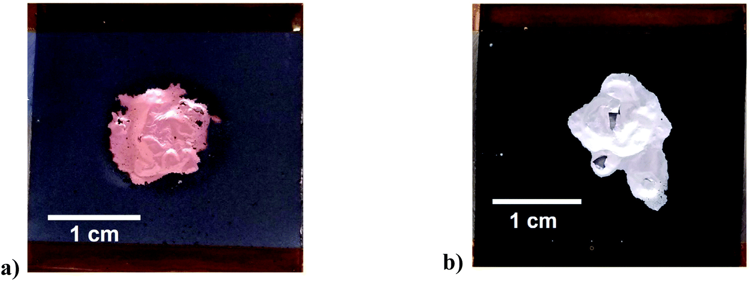 | ||
| Fig. 2 Images showing the effect of ultrasound on the front side of a QC reject: (a) anode, and (b) cathode sheets. The anode was delaminated in a solution of 0.05 M citric acid; the cathode was delaminated in a solution of 0.1 M NaOH. The sonotrode was 20 mm in diameter, with 120 W cm−2 power intensity applied for 3 seconds. Sample size was 3 cm × 3 cm, placed 2.5 mm away from the sonotrode. | ||
Delamination of the nickel manganese cobalt oxide (NMC) cathode with a PVDF binder was successful using an aqueous solution of 0.1 M NaOH as shown in Fig. 2(b). The same could also be achieved using an organic solvent, such as N-methyl-2-pyrrolidone (NMP). The 3 s experiment time was insufficient for chemical etching to delaminate but it clearly aids in breaking the interfacial adhesion. In the case of Fig. 2b it was found that the addition of 10 v/v% ethylene glycol (EG) as a wetting agent/polymer modifier aided the rapid delamination. This shows that the technique is not dependent on the chemistry of the active material. The technique was used for a variety of cathode materials including uncycled QC reject NMC/NCA + LMO, NMC-532, uncycled LFP from commercial cells and a range of EoL car cells with different chemistries. The technique worked equally well on all samples but is more dependent on the binder and its aging.
Fig. 3a shows an example of the action of the cavitation and acoustic pressure in the delamination process of a lithium ion battery anode in deionized water. The images were taken with a high speed camera (20k frames per s). The graphite coating after 0.2 seconds (Fig. 3b) can be seen first to bulge away from the copper current collector, followed by peeling off in patches due to the cavitation at the interface between the coating and copper foil created by the pressure wave. This delaminated material is finally pulverised after only 0.5 seconds, mainly through the action of the cavitation (Fig. 3c).
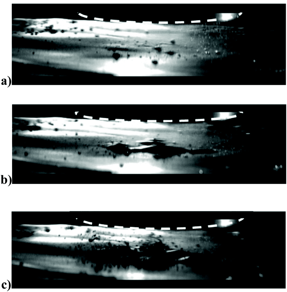 | ||
| Fig. 3 Images showing snapshots taken from a high speed camera (20k frames per s) during ultrasonic delamination of a carbon/CMC-SBR/copper electrode: (a) 0.01 second after power-on; (b) 0.2 seconds after power-on; (c) 0.5 seconds after power-on. The sonotrode (outlined by the dashed line) was 20 mm in diameter, with 120 W cm−2 power intensity, at 5 mm from the substrate. The solvent was deionized water. | ||
Ultrasonic delamination of car battery electrodes
The electrodes used in pouch cell EV batteries are typically in the order of 20 cm wide. To delaminate these the high power ultrasonic unit was constructed with a front face on the sonotrode of area 1.5 × 21 cm2 (Fig. S1†) which operated at 20 kHz and a maximum power of 2200 W, which produces a max power intensity of 70 W cm−2. The effect of the ultrasonic delamination on both anode and cathode can be seen in Fig. 4. Interestingly, delamination is easier and faster when the electrode material is moving under the sonotrode, as crack propagation aids delamination. These cracks will start at voids in the numerous interfacial boundaries of the layered structure of the electrode. For both cathode and anode, it can be seen that the aluminium and copper foil current collectors have been effectively delaminated on both sides, leaving the foil relatively free from active material. These delaminated active materials were examined with scanning electron microscopy, and can be seen in Fig. S5.† It was observed that the physical structure of both cathode and bulk anode materials were unaffected by the delamination process. However, the larger particles of graphite in the anode appeared to have been “cleaned” of smaller particles, most likely a carbon black conductive additive. As above, while delamination will occur in deionised water, the efficiency of separation can be improved by adjustment of the pH to etch the substrate, or by adding wetting agents to aid the collapse of the cavitation bubbles. While binder-specific solvents such as NMP also enable rapid delamination by partially dissolving the binder, this is probably not a viable practical option due to its cost and toxicity. Volatile solvents such as ethanol are unsuitable due to their volatility, lack of polymer solubility and inability to support suitable cavitation.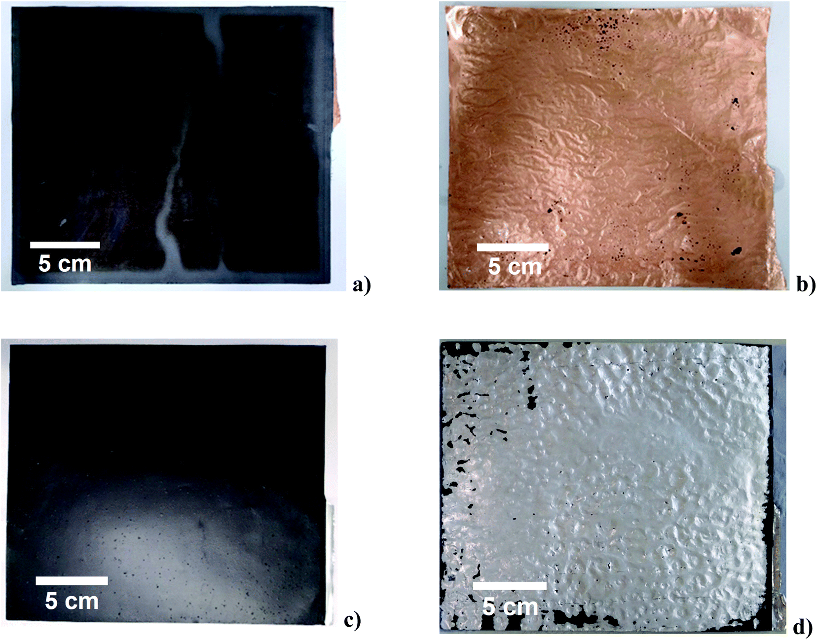 | ||
| Fig. 4 Images (each 22 cm × 23 cm) showing: carbon/CMC-SBR/copper electrode (a) before, and (b) after delamination in deionised water (0.05 M citric acid), and NMC/PVDF/aluminium electrode (c) before, and (d) after delamination in 0.1 M NaOH. The delamination was through the 1.5 × 21 cm2 sonotrode with a power intensity of 70 W cm−2, at a sheet feeding speed of 2 cm s−1. | ||
Depending on the choice of delaminating solvent, the delaminated active material will also contain the polymer binder. Additionally, a significant proportion of battery waste material originates from production scrap where the polymer and active materials have not experienced cycling. In principle these materials could be short loop recycled by simply retacking the surface of the polymer binder using an appropriate organic solvent which does not dissolve the polymer. This was attempted for both anode and cathode material where PVDF was the binder and it was found that acetone could be used to rebind the active materials to the substrate. Recent work has demonstrated the use of hybrid water-dispersible binder systems for anodes and cathodes.19,20
The samples in Fig. 4 resulted in recovery of 99.5% of active material for both the anode and cathode. The unrecovered 0.5% of active material comprises particles that are too small (<3 μm) to easily be recovered via filtration techniques, most likely carbon black additive, which has particle sizes of 0.05 to 0.1 μm. This compares with about 67% efficiency recovering cathode material using a stirred sulfuric acid solution.10 The delamination rate for both electrodes with ultrasound was 44 cm2 s−1; hence, the small unit shown in Fig. S1† is capable of processing 350 of the 20 × 20 cm electrodes per hour. The cost of running the process was calculated to be $0.10 to 0.15 kg−1 of electrode material. Ultrasound is commonly used for soldering, welding, extraction, cutting and drilling so the technology is easily scalable for this type of application.
The ultrasonic delamination technique is designed to work on whole rather than shredded electrodes, which makes it particularly suitable for production scrap and quality control reject material which accounts for approximately 5 to 20% of production. While current cell designs do not lend themselves to disassembly, a recent review shows that disassembly is financially preferable to shredding and produces higher purity products with a lower chemical and energy requirement.3 Many manufacturers are also designing cells which are easier to disassemble and recycle.
Conclusion
This study has shown that rapid delamination of active material from the current collector of a lithium ion battery can be achieved using high powered ultrasound. Fast frame video was used to elucidate the delamination mechanism and it was shown that cavitation enabled the adhesive bond between the active layer and the current collector to be broken within 0.5 s of entering the high power ultrasound region. The efficiency of the delamination process is strongly affected by the type of polymer binder with water-dispersible binders such as SBR/CMC being more rapidly stripped. It was shown that delamination could be further optimised using wetting agents and pH modification. Production scrap could be rapidly recycled by simply wetting the active material/binder mixture with an organic solvent. High rates of material recovery and throughput coupled with the ease of process scale up make high-powered ultrasonic delamination a step-change in battery recycling.Author contributions
Chunhong Lei – experimental, writing – original draft, writing – review & editing. Iain Aldous – experimental. Jennifer Hartley – writing – original draft, writing – review & editing. Dana Thompson – experimental, writing – original draft. Sean Scott – experimental, writing – review & editing. Rowan Hanson – visualisation. Paul Anderson – project administration. Emma Kendrick – supervision, writing – original draft. Rob Sommerville – resources. Karl Ryder – funding acquisition, supervision. Andrew Abbott – conceptualisation, supervision, writing – original draft, writing – review & editing.Conflicts of interest
There are no conflicts of interest to declare.Acknowledgements
The authors would like to thank the Faraday Institution (grant codes FIRG005 and FIRG006, Project website https://relib.org.uk) for funding.References
- G. Harper, R. Sommerville, E. Kendrick, L. Driscoll, P. Slater, R. Stolkin, A. Walton, P. Christensen, O. Heidrich, S. Lambert, A. Abbott, K. Ryder, L. Gaines and P. Anderson, Nature, 2019, 575, 75–86 CrossRef CAS PubMed.
- J.-P. Skeete, P. Wells, X. Dong, O. Heidrich and G. Harper, Energy Res. Soc. Sci., 2020, 69, 101581 CrossRef.
- D. L. Thompson, J. M. Hartley, S. M. Lambert, M. Shiref, G. D. J. Harper, E. Kendrick, P. Anderson, K. S. Ryder, L. Gaines and A. P. Abbott, Green Chem., 2020, 22, 7585–7603 RSC.
- S. Gifford, The Gigafactory Boom: the Demand for Battery Manufacturing in the UK, 2019. https://faraday.ac.uk/wp-content/uploads/2019/08/Faraday_Insights-2_FINAL.pd Search PubMed.
- M. Pagliaro and F. Meneguzzo, Heliyon, 2019, 5, e01866 CrossRef PubMed.
- Critical Raw Materials Resilience: Charting a Path towards greater Security and Sustainability, 2020. https://eur-lex.europa.eu/legal-content/EN/TXT/?uri=CELEX:52020DC0474 Search PubMed.
- M. Humphries, Critical Minerals and U.S. Public Policy, 2019. https://www.everycrsreport.com/reports/R45810.html#_Toc13841346 Search PubMed.
- J. Li, P. Shi, Z. Wang, Y. Chen and C. C. Chang, Chemosphere, 2009, 77, 1132–1136 CrossRef CAS.
- L. P. He, S. Y. Sun, X. F. Song and J. G. Yu, Waste Manag., 2015, 46, 523–528 CrossRef CAS PubMed.
- J. Marshall, D. Gastol, R. Sommerville, B. Middleton, V. Goodship and E. Kendrick, Metals, 2020, 10, 773 CrossRef CAS.
- J. S. Terreblanche, D. L. Thompson, I. M. Aldous, J. Hartley, A. P. Abbott and K. S. Ryder, J. Phys. Chem. C, 2020, 124, 14622–14631 CrossRef CAS.
- G. J. Price, M. Ashokkumar, M. Hodnett, B. Zequiri and F. Grieser, J. Phys. Chem. B, 2005, 109, 17799–17801 CrossRef CAS PubMed.
- A. Moussatov, C. Granger and B. Dubus, Ultrason. Sonochem., 2003, 10, 191–195 CrossRef CAS PubMed.
- X. Ma, B. Huang, G. Wang and M. Zhang, Ultrason. Sonochem., 2017, 34, 164–172 CrossRef CAS PubMed.
- N. Ochiai and J. Ishimoto, Ultrason. Sonochem., 2015, 26, 351–360 CrossRef CAS PubMed.
- K. Yasui, Y. Iida, T. Tuziuti, T. Kozuka and A. Towata, Phys. Rev. E: Stat., Nonlinear, Soft Matter Phys., 2008, 77, 016609 CrossRef PubMed.
- B. Dubus, C. Vanhille, C. Campos-Pozuelo and C. Granger, Ultrason. Sonochem., 2010, 17, 810–818 CrossRef CAS PubMed.
- G. S. B. Lebon, I. Tzanakis, G. Djambazov, K. Pericleous and D. G. Eskin, Ultrason. Sonochem., 2017, 37, 660–668 CrossRef CAS PubMed.
- D. Versaci, R. Nasi, U. Zubair, J. Amici, M. Sgroi, M. A. Dumitrescu, C. Francia, S. Bodoardo and N. Penazzi, J. Solid State Electrochem., 2017, 21, 3429–3435 CrossRef CAS.
- D. Bresser, D. Buchholz, A. Moretti, A. Varzi and S. Passerini, Energy Environ. Sci., 2018, 11, 3096–3127 RSC.
Footnote |
| † Electronic supplementary information (ESI) available. See DOI: 10.1039/d1gc01623g |
| This journal is © The Royal Society of Chemistry 2021 |