Microfluidic electrosynthesis of thiuram disulfides†
Siyuan
Zheng
,
Kai
Wang
 * and
Guangsheng
Luo

The State Key Lab of Chemical Engineering, Department of Chemical Engineering, Tsinghua University, Beijing 100084, China. E-mail: kaiwang@tsinghua.edu.cn; Fax: +8610 6278 8568; Tel: +86 10 6278 8568
First published on 10th December 2020
Abstract
An electrolytic approach to sodium dithiocarbamates based on a microfluidic reactor is proposed for the green synthesis of thiuram disulfides, which are versatile free radical initiators. The electro-oxidation reactions avoid the over-oxidation of sodium dithiocarbamates and the generation of waste salts, which have perplexed the industry for a long time. This microfluidic electrolysis method prevents solid deposition by introducing liquid–liquid Taylor flow into the microchannel, and promotes the synthesis efficiency of thiuram disulfides with the enlargement of the electrode-specific surface area. The highest yield of thiuram disulfide was 88% in the experiment without any oxidation by-products. The Faraday efficiencies of most reactions are higher than 96%, showing the excellent electronic utilization. In addition to improving the environmental friendliness of sodium dithiocarbamate oxidation, the electrosynthesis method helps to create a cyclic technology of thiuram disulfide synthesis via the combination of sodium dithiocarbamate generation in a packed bed reactor. The cyclic technology finally achieved >99% atom utilization in thiuram disulfide synthesis from secondary amines and carbon disulfide.
Introduction
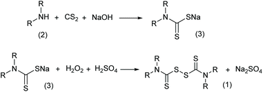
Thiuram disulfides, also called thioperoxydicarbonic diamides (1 in Scheme 1), are versatile polysulfide compounds. Since they are able to rapidly decompose into free radicals when heated,1 thiuram disulfides are highly efficient free radical initiators in C–S coupling reactions,2,3 oxidative-addition reactions,4 and free radical polymerization reactions.5 Thiuram disulfides were once developed as medicines to cure chronic alcohol dependence.6 Now they are normally applied as vulcanization accelerators in the rubber industry. Thiuram disulfides are also fungicides and animal repellents in agriculture.7,8Traditionally, thiuram disulfides are synthesized in two steps: (1) a condensation reaction of secondary amine (2 in Scheme 2) and carbon disulfide (CS2) to form dithiocarbamate and (2) an oxidation reaction of the dithiocarbamate (Scheme 2) to form a disulfide bond.9 Since dithiocarbamate is not stable, it has to be converted to ions, for example the sodium salt (3) in Scheme 2, which have good water solubility and better stability for storage. However, when transiting sodium dithiocarbamate into thiuram disulfide, dithiocarbamate has to be regenerated from the salt solution by adding H2SO4 or HCl, and simultaneously oxidized using hydrogen peroxide or chlorine in solution. During the oxidation, thiocarboxylic acid is easily over-oxidized to sulfonates and their derivatives,10 which lead to high chemical oxygen demand (COD) of the wastewater. Therefore, batch reactors fed an acid and oxidant mixture with slow dripping are commonly used in the synthesis of thiuram disulfides. Moreover, waste salts, such as Na2SO4 and NaCl, have been listed as hazardous wastes by governments, because they containe a lot of organic componds as impurities. To improve its environmental friendliness, the use of oxygen was once proposed, instead of strong oxidants, in thiuram disulfide synthesis reaction.11 Although over-oxidization can be prevented by the decrease of reactant activity, the low reaction rate and high safety risk of using oxygen in the reaction system containing carbon disulfide still restricts its industrial application.
In addition to the traditional chemical oxidation approaches, an electrolysis method (Scheme 3) was proposed in the 1970s with new advantages.9 Employing electrodes to displace chemical reagents, this method has excellent atom economy and more adjustable oxidation ability. More importantly, the electrolysis reaction does not produce waste salts, which is crucial for increasing the environmental friendliness of thiuram disulfide syntheses. However, the conversion of sodium dithiocarbamate was only in the range of 10% to 25% in the literature,12 and still needs improvement. In addition, different from the study focusing on the electrosynthesis of disulfides in liquid states,13 the sediment of thiuram disulfide on the electrode finally limited the application of this advanced synthesis method.
With the development of electrochemical technologies and equipment, the microfluidic electro-oxidation method opens a new door to implement the electrosynthesis of thiuram disulfides. Microfluidic electrosynthesis, also called flow electrosynthesis and microreaction electrosynthesis,14,15 has the advantages of microfluidics, flow chemistry, and electrochemistry technology,16–19 which overcomes the difficulties of conventionally organic synthesis by creating a new reaction method. The investigation of microfluidic electrosynthesis also helps us to understand more about flow and transport of the electrochemical process.20 The distances between electrodes in microfluidic reactors are greatly reduced promoting ionic conduction by reducing the ohmic resistance.16,18,21 Microchannels are employed as the reaction chambers, which improve the mass and heat transfer rates of reactions in contrast to the thick chamber in traditional electrolysers.22,23 Moreover, the regular flow patterns in micro-fluidic reactors, such as liquid–liquid parallel flow that employs stable laminar fluids, are able to improve the controllability of electrochemical reactions.24,25 In addition, the microfluidic electro-synthesis reactor is also an important element of the flow chemistry system,26 which is able to achieve end-to-end organic chemical production.27
In this paper, a microfluidic electrosynthesis method for the preparation of thiuram disulfides is proposed, which employed sodium dithiocarbamate electrolysis in microchannel reactors with parallel electrodes. A multiphasic electrolysis process was proposed to dissolve thiuram disulfides on electrodes in situ to avoid solid sediment. The electrolytic method exhibits excellent yields, production purities, and Faraday efficiencies. A solution cyclic technology is finally created to achieve the synthesis of thiuram disulfides from the basic secondary amines and carbon disulfide with the assistance of microfluidic electrosynthesis, which realizes the green synthesis of thiuram disulfides.
Results and discussion
Electrolysis of sodium dithiocarbamate in an electrolyser
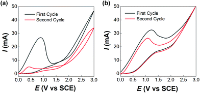
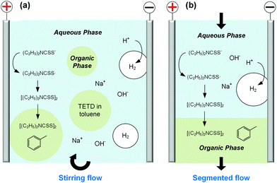
Before developing the microfluidic electrosynthesis technology, we implemented the electrolysis of sodium dithiocarbamate via a batch electrolyser at first to understand the characteristics of the oxidation reaction. The synthesis of tetraethylthiuram disulfide (TETD) was selected as a representative, since it is more widely used in applications. The experiment started from a 0.15 mol L−1 sodium diethyldithiocarbamate (NaEt2DTC) aqueous solution, whose cyclic voltammetry on a Pt work electrode was detected by a workstation (PARSTAT 3000A-DX, AMETEK Inc.) with a 3-electrode electrolyser (Fig. S1 in the ESI†). Fig. 1(a) shows the result. The growth of oxidative current above 0.5 V in the positive scan shows that the electrolysis of NaEt2DTC is accessible at low potentials in contrast to standard calomel electrode. No other oxidative peaks were observed at less than 3 V. An irreversible process is shown by the negative scan. The potential scan was performed for 2 cycles, and the second cycle showed much lower oxidative current for the deposition of TETD on the anode during the electrolysis process. Based on the idea of in situ dissolution of thiuram disulfide during electrolysis, toluene, with acceptable solubility of TETD (about 73 g in 100 g toluene at 25 °C), was employed, and the result is given in Fig. 1(b). 100 mL toluene and 100 mL NaEt2DTC aqueous solution formed an emulsified electrolyte in the electrolysis experiment. Although the oxidative current of the second scan in Fig. 1(b) was still a little lower than in the first scan, the improvement of the electrolysis environment due to this solvent dissolution method exhibits its advantage. A photo in the ESI (Fig. S6a†) shows the electrodes during the multiphasic electrolysis experiment.After studying the cyclic voltammograms of NaEt2DTC electrolysis, a potentiostatic electrolysis experiment was carried out with a multiphasic system containing 100 mL of 0.15 mol L−1 NaEt2DTC solution and 100 mL toluene in the batch electrolyser. Within 100 min of electrolysis at 2.0 V, only the peaks of NaEt2DTC, toluene, and TETD were obviously observed in the HPLC spectra after electrolysis (Fig. S9†). According to our previous result,28 the over-oxidation products also have UV absorbance at 254 nm, which is the HPLC detection wavelength in this study, but they were not detected. Another advantage of employing toluene is its weak wetting ability on a Pt electrode, which provides better contact of NaEt2DTC solution with the anode. Fig. S5(a) and S5(b)† show that the liquid–liquid contact angle of toluene on a platinum surface is about 100°. The electrolysis reaction was also found to have little effect on the wetting property of toluene. Above all, Fig. 2(a) shows a schematic of the electrolysis process. At the anode, Et2DTC− loses an electron to form a free radical,29 which quickly self-condensed to TETD. Then, TETD moves to the organic phase, after it contacts with the toluene droplets. H2 is generated at the cathode, which leaves NaOH in the aqueous phase. Although effective mixing of the electrolyte solution and toluene had been achieved in the experiment, the TETD yields of a series of experiments in the batch electrolyser were found only between 2% and 15%, even at 2.0 V electrolysis potential as shown in Table 1. This phenomenon implies that the small specific area of the work electrode (2 cm2 per 250 mL) in the batch reactor and random contact of toluene droplets on electrodes influence the apparent rate of the reaction, which should be improved using a more advantageous reactor.
| Potential (V) | NaEt2DTC solution/toluene (mL mL−1) | Electrolysis time (min) | Yield of TETD (%) |
|---|---|---|---|
| 2.0 | 100/100 | 20 | 2% |
| 2.0 | 100/100 | 40 | 4% |
| 2.0 | 100/100 | 60 | 7% |
| 2.0 | 100/100 | 80 | 11% |
| 2.0 | 100/100 | 100 | 15% |
Microfluidic electrosynthesis of thiuram disulfides
In order to develop an efficient electrolysis reactor to synthesize thiuram disulfides, an ideal reaction cell should have a structure shown in Fig. 2(b). The aqueous and the organic phases flow alternately through parallel electrodes to continuously carry out the oxidation and dissolution processes. The distance between electrodes is also best to reduce to a small value to increase the electrode specific surface area in the flow cell and maintain the stability of liquid–liquid segmented flow via the capillary effect. Based on this idea, a microchannel reactor containing platinum electrodes was created as shown in Fig. 3. In the centre of the reactor, a 61, 97, or 245 mm long microchannel with 2 mm width was curved in 0.3 mm thick fluorinated ethylene propylene (FEP) plates working as the reaction channel. Beside the channel plate, Pt electrodes were parallelly placed. The channel thickness was selected based on the balance between reactant residence time and electrode distance, which had increased the specific area of the work electrode to 33 cm2 mL−1, more than 4000 times that in the batch electrolyser. Pt wires were welded on both electrodes to connect to the external circuit. The channel plate was sealed by 0.5 mm Teflon plates. The sealing plates were sandwiched by polyvinylidene fluoride (PVDF) modules for connection with tube fittings. The whole reactor was finally fixed by shells with fastening screws. Both wires and tubes (perfluoroalkoxy alkanes, PFA) in this reactor were sealed by commercial fittings (PEEK, Idex Health & Science) as shown in Fig. 3(b). Some photos of the reactor are given in Fig. S2(a) and (b) in the ESI.†Employing the microfluidic reactor as the core equipment, we built a continuous electrosynthesis reaction platform as shown in Fig. 4(a). In this platform, sodium dithiocarbamate solution and toluene, delivered by continuous syringe pumps (MSP1-E1, Longer) individually, were premixed in a biphasic mixer, which had a coaxial internal structure.30,31 Fig. S2(c)† shows that the interior of the mixer was a stainless-steel capillary with 0.6 mm outer diameter, and the tunnel of the mixer was a PFA tube with 1.0 mm inner diameter (Idex Health & Science). Both the tube and the capillary were assembled in a Tee-connector (PEEK, Idex Health & Science). Sodium dithiocarbamate solution from the capillary was dispersed as droplets in toluene, forming a regular liquid–liquid Taylor flow32,33 in the tube before flowing into the microfluidic reactor, as shown by Fig. 4(b). The droplet length was consistent in each test, but it varied from 1.4 to 2.5 mm in different tests due to variation of flow rates. The regular flow pattern ensured a periodic electrolysis and electrode washing, which maintained the reaction stability. However, H2 from the cathode mixed into the biphasic mixture, making the reaction a gas–liquid–liquid triphasic system. Due to the appearances of bubble and droplet coalescence, the droplet and bubbles are not uniform at the outlet.
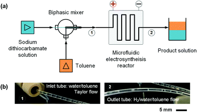 | ||
| Fig. 4 Continuous reaction platform for the electrosynthesis of thiuram disulfides. (a) Schematics of the microfluidic platform. (b) Pictures of the liquid–liquid Taylor flow at the inlet of the microfluidic reactor and the gas–liquid–liquid triphasic flow at the outlet of the reactor. Fig. S2(d)† shows a picture of the microfluidic reaction platform in the ESI.† | ||
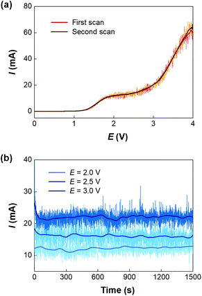
With the microfluidic electrosynthesis platform, continuous electrolysis of NaEt2DTC solution was carried out. The effect of cell potential was first investigated. Fig. 5(a) shows the linear sweep voltammetry on the Pt anode of the microfluidic reactor with the opposite Pt sheet acting as both the counter electrode and reference electrode. Different from the cyclic voltammetry experiments in the batch electrolyser, the segmented flow and the generation of hydrogen bubbles in the reaction channel led to oscillating currents, which had been observed in other previous reports.34,35 After smoothing the current curves, a peak current was found at about 2.0 V, and the curves of two scans fit well with each other. Considering that low voltage would lead to a low reaction rate, we further carried out a potentiostatic electrolysis experiment in the range of 2–3 V. Fig. 5(b) shows the results. Although higher voltage led to larger current, a spontaneous emulsification phenomenon was observed in the outlet solution at the voltage more than 2.0 V, which brought difficulty in phase separation. Besides, NaOH is one of the products of the cathodic process and a competitive reaction between OH− and Et2DTC− exists under electrolysis potential more than 2.0 V, according to Fig. S7.† Thus, 2.0 V seems to be an optimized potential from the engineering point of view. Fig. S6(b) and S6(c)† show the electrode surfaces after electrolysis. Since TETD had been well dissolved in toluene, the electrode surface was protected by the multiphasic system.
After confirming the cell potential of the microfluidic reactor, the effects of operating parameters including reactor volume, flow rate, and NaEt2DTC concentration were studied. Entries 1–6 in Table 2 show that the TETD yield increases as the liquid flow rate decreases due to the extension of residence time in the reactor. For the effect of flow rates of the aqueous and organic phases, entries 7–9 in Table 2 indicate that a higher flow rate ratio of the organic phase to the aqueous phase leads to higher yield due to the better dissolution of TETD. However, the heavy use of solvent reduced the TETD concentration in the organic phase. Table 2 (entries 10–12) also shows the experimental results for different NaEt2DTC concentrations. It can be seen from these data that the NaEt2DTC concentration from 0.14 to 0.49 mol L−1 had little effect on the TETD yield. The highest TETD yield in the experiment reached 70% within 9 s (evaluated by dividing the reaction channel volume by the total liquid flow rate) showing the high working efficiency of the microfluidic reactor in contrast to the batch electrolyser. The Faraday efficiencies of all tests were higher than 96%, which exhibited the high electronic utilization of the microfluidic electrolysis process. It is worth noting that we did not detect additional by-product in the HPLC analysis and NMR analysis (Fig. S13c†) of the reaction products.
| Entry | Total flow rate of liquids (mL min−1) | Reaction channel volume (mL) | Flow rate ratio of NaEt2DTC solution to toluene (v/v) | Concentration of NaEt2DTC (mol L−1) | TETD yield (%) |
|---|---|---|---|---|---|
| 1 | 0.5 | 0.15 | 1![[thin space (1/6-em)]](https://www.rsc.org/images/entities/char_2009.gif) : :![[thin space (1/6-em)]](https://www.rsc.org/images/entities/char_2009.gif) 1 1 |
0.075 | 69% |
| 2 | 0.7 | 0.15 | 1![[thin space (1/6-em)]](https://www.rsc.org/images/entities/char_2009.gif) : :![[thin space (1/6-em)]](https://www.rsc.org/images/entities/char_2009.gif) 1 1 |
0.075 | 63% |
| 3 | 1.0 | 0.15 | 1![[thin space (1/6-em)]](https://www.rsc.org/images/entities/char_2009.gif) : :![[thin space (1/6-em)]](https://www.rsc.org/images/entities/char_2009.gif) 1 1 |
0.075 | 57% |
| 4 | 1.2 | 0.15 | 1![[thin space (1/6-em)]](https://www.rsc.org/images/entities/char_2009.gif) : :![[thin space (1/6-em)]](https://www.rsc.org/images/entities/char_2009.gif) 1 1 |
0.075 | 53% |
| 5 | 1.5 | 0.15 | 1![[thin space (1/6-em)]](https://www.rsc.org/images/entities/char_2009.gif) : :![[thin space (1/6-em)]](https://www.rsc.org/images/entities/char_2009.gif) 1 1 |
0.075 | 48% |
| 6 | 1.8 | 0.15 | 1![[thin space (1/6-em)]](https://www.rsc.org/images/entities/char_2009.gif) : :![[thin space (1/6-em)]](https://www.rsc.org/images/entities/char_2009.gif) 1 1 |
0.075 | 43% |
| 7 | 1.0 | 0.15 | 1![[thin space (1/6-em)]](https://www.rsc.org/images/entities/char_2009.gif) : :![[thin space (1/6-em)]](https://www.rsc.org/images/entities/char_2009.gif) 3 3 |
0.075 | 70% |
| 8 | 1.0 | 0.15 | 2![[thin space (1/6-em)]](https://www.rsc.org/images/entities/char_2009.gif) : :![[thin space (1/6-em)]](https://www.rsc.org/images/entities/char_2009.gif) 3 3 |
0.075 | 64% |
| 9 | 1.0 | 0.15 | 3![[thin space (1/6-em)]](https://www.rsc.org/images/entities/char_2009.gif) : :![[thin space (1/6-em)]](https://www.rsc.org/images/entities/char_2009.gif) 1 1 |
0.075 | 49% |
| 10 | 1.0 | 0.06 | 1![[thin space (1/6-em)]](https://www.rsc.org/images/entities/char_2009.gif) : :![[thin space (1/6-em)]](https://www.rsc.org/images/entities/char_2009.gif) 1 1 |
0.140 | 38% |
| 11 | 1.0 | 0.06 | 1![[thin space (1/6-em)]](https://www.rsc.org/images/entities/char_2009.gif) : :![[thin space (1/6-em)]](https://www.rsc.org/images/entities/char_2009.gif) 1 1 |
0.250 | 36% |
| 12 | 1.0 | 0.06 | 1![[thin space (1/6-em)]](https://www.rsc.org/images/entities/char_2009.gif) : :![[thin space (1/6-em)]](https://www.rsc.org/images/entities/char_2009.gif) 1 1 |
0.490 | 34% |
In addition to the potentiostatic electrolysis, the galvanostatic electrolysis method was also tested in the experiment. However, the Faraday efficiency of a galvanostatic electrolysis experiment was only from 88% to 96% with currents between 10 and 40 mA as shown by Table S1 in the ESI,† which was probably because of the competitive electrolysis of water. Since the aim is to improve the environmental friendliness of thiuram disulfide synthesis and to prevent the over-oxidation of sodium dithiocarbamate, the potentiostatic method was more suitable to the goal of this study, although it was not as robust as the galvanostatic electrolysis method. In order to test the reliability of the potentiostatic electrolysis method, a 3-hour electrolysis experiment was carried out using 0.5 mol L−1 NaEt2DTC, 1.0 mL min−1 total flow rate, 1![[thin space (1/6-em)]](https://www.rsc.org/images/entities/char_2009.gif) :
:![[thin space (1/6-em)]](https://www.rsc.org/images/entities/char_2009.gif) 1 rate ratio of NaEt2DTC solution to toluene, and 0.15 mL reactor volume. The results showed that 3.14 g TETD (about 10 mmol) was obtained with 47% yield and 100% Faraday efficiency. Besides, larger scaled reactions can also be achieved using parallel microfluidic electrolysis reactors. As shown in Fig. S3,† when using two reactors with total reaction channel of 0.3 mL, 3.07 g TETD was synthesized within 1.5 h with 46.5% yield and 100% Faraday efficiency. In contrast, the batch electrolysis in Table 1 only produced 0.336 g TETD in the same reaction time. Therefore, the working ability of the microfluidic reactor is nearly 10 times higher than that of the batch reactor.
1 rate ratio of NaEt2DTC solution to toluene, and 0.15 mL reactor volume. The results showed that 3.14 g TETD (about 10 mmol) was obtained with 47% yield and 100% Faraday efficiency. Besides, larger scaled reactions can also be achieved using parallel microfluidic electrolysis reactors. As shown in Fig. S3,† when using two reactors with total reaction channel of 0.3 mL, 3.07 g TETD was synthesized within 1.5 h with 46.5% yield and 100% Faraday efficiency. In contrast, the batch electrolysis in Table 1 only produced 0.336 g TETD in the same reaction time. Therefore, the working ability of the microfluidic reactor is nearly 10 times higher than that of the batch reactor.
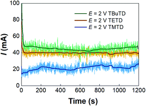
The microfluidic electrosynthesis method was then extended to the preparations of tetramethylthiuram disulfide (TMTD) and tetrabutylthiuram disulfide (TBuTD) to test the generality of the method. Fig. S8† shows that the peak currents in both linear sweep voltammetries of sodium dimethyldithiocarbamate (NaMe2DTC) and sodium dibutyldithiocarbamate (NaBu2DTC) are at approximately 2.0 V, which is the same as that of NaEt2DTC. The response currents in the potentiostatic electrolysis experiments are depicted in Fig. 6. In contrast to the syntheses of TETD and TBuTD, the current of TMTD electrolysis synthesis is much lower. Table 3 (entries 1–4) also shows the yields of TMTD are much lower than that of TBuTD. The Faraday efficiency of NaMe2DTC electrolysis was from 77% to 92% in those tests, which were different from the results of TETD either. However, no side reaction current peak was present in the linear sweep voltammetry of NaMe2DTC, and no obviously by-product was detected with HPLC and NMR analyses, as shown by Fig. S10 and S13.† We therefore suspected that electrolysis of water might appear in the reaction. The rules of TBuTD electrosynthesis are almost the same as for TETD. 2.0 V cell potential was enough to avoid severe emulsification and maintain high Faraday efficiency, which were close to 100%. Entries 5–9 in Table 3 shows that the yield of TBuTD increases obviously with the decrease of total liquid flow rate, for the extension of residence time in the reactor. The highest yield of TBuTD is 88%. A potentiostatic electrolysis of NaBu2DTC in the batch reactor was also carried out in the experiment. For 100 mL 0.14 mol L−1 NaBu2DTC solution with equal volume of toluene, only 12% TBuTD yield was obtained within 100 min of electrolysis. In contrast, 100 min of electrolysis in the microfluidic reactor can treat 75 mL of 0.15 mol L−1 NaBu2DTC solution and resulted in 64% TBuTD yield as shown in Table 3 (entry 8).
| Entry | Products | Total flow rate of liquids (mL min−1) | Microchannel volume (mL) | Flow rate ratio of aqueous solution to toluene (v/v) | Concentration of reactant (mol L−1) | Product yield (%) |
|---|---|---|---|---|---|---|
| 1 | TMTD | 0.5 | 0.06 | 1![[thin space (1/6-em)]](https://www.rsc.org/images/entities/char_2009.gif) : :![[thin space (1/6-em)]](https://www.rsc.org/images/entities/char_2009.gif) 1 1 |
0.113 | 42% |
| 2 | TMTD | 1.0 | 0.06 | 1![[thin space (1/6-em)]](https://www.rsc.org/images/entities/char_2009.gif) : :![[thin space (1/6-em)]](https://www.rsc.org/images/entities/char_2009.gif) 1 1 |
0.113 | 31% |
| 3 | TMTD | 0.5 | 0.15 | 1![[thin space (1/6-em)]](https://www.rsc.org/images/entities/char_2009.gif) : :![[thin space (1/6-em)]](https://www.rsc.org/images/entities/char_2009.gif) 1 1 |
0.162 | 27% |
| 4 | TMTD | 1.0 | 0.15 | 1![[thin space (1/6-em)]](https://www.rsc.org/images/entities/char_2009.gif) : :![[thin space (1/6-em)]](https://www.rsc.org/images/entities/char_2009.gif) 1 1 |
0.162 | 25% |
| 5 | TBuTD | 0.5 | 0.15 | 1![[thin space (1/6-em)]](https://www.rsc.org/images/entities/char_2009.gif) : :![[thin space (1/6-em)]](https://www.rsc.org/images/entities/char_2009.gif) 1 1 |
0.147 | 88% |
| 6 | TBuTD | 0.7 | 0.15 | 1![[thin space (1/6-em)]](https://www.rsc.org/images/entities/char_2009.gif) : :![[thin space (1/6-em)]](https://www.rsc.org/images/entities/char_2009.gif) 1 1 |
0.147 | 81% |
| 7 | TBuTD | 1.0 | 0.15 | 1![[thin space (1/6-em)]](https://www.rsc.org/images/entities/char_2009.gif) : :![[thin space (1/6-em)]](https://www.rsc.org/images/entities/char_2009.gif) 1 1 |
0.147 | 75% |
| 8 | TBuTD | 1.5 | 0.15 | 1![[thin space (1/6-em)]](https://www.rsc.org/images/entities/char_2009.gif) : :![[thin space (1/6-em)]](https://www.rsc.org/images/entities/char_2009.gif) 1 1 |
0.147 | 64% |
| 9 | TBuTD | 1.8 | 0.15 | 1![[thin space (1/6-em)]](https://www.rsc.org/images/entities/char_2009.gif) : :![[thin space (1/6-em)]](https://www.rsc.org/images/entities/char_2009.gif) 1 1 |
0.147 | 45% |
Generation of sodium dithiocarbamates via a packed bed reactor
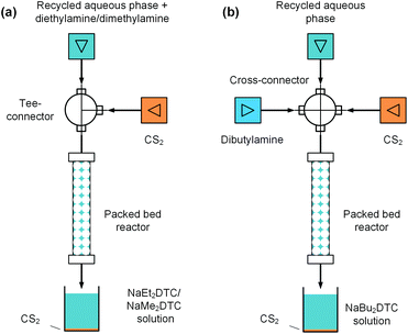
In the above electrolysis experiment, high selectivity of thiuram disulfides was successfully obtained in the microfluidic reactor. Although the reaction yields have been much higher than those in the previous literature12 and the batch electrolysis process in this study, they are still away from 100% due to the low sodium dithiocarbamate conversions. In fact, highly concentrated NaOH will be yielded when the sodium dithiocarbamate conversion is high, which increases the possibility of water electrolysis. Thus, it is better to reuse the sodium dithiocarbamate in solution after electrolysis. At the beginning of this paper, we have mentioned that the synthesis of thiuram disulfides has two steps, and the first step is a condensation reaction between NaOH, secondary amine, and carbon disulfide to prepare sodium dithiocarbamate. Owing to the high selectivity of the electrolysis reaction, the NaOH in the aqueous solution after electrolysis is an ideal source of the condensation reaction, and it is also beneficial for recycling the unreacted sodium dithiocarbamate if the aqueous solution can be reused. Therefore, we further developed a flow technology for the condensation reaction based on a packed bed reactor, as shown in Fig. 7. The reactor was built from an empty HPLC column (4.6 mm inner diameter and 100 mm length, BAIJIALIDA Co., Ltd), fully packed with 0.9 mm stainless-steel beads. Due to the low solubility of carbon disulfide in the aqueous phase, the beads helped to mix the biphasic reactants in the tortuous interior space in the reactor. Taking the synthesis of NaEt2DTC as an example, the water-soluble diethylamine was firstly added into the recycled aqueous solution during the experiment; then, a Tee-connector (0.5 mm inner diameter, VICI) shown by Fig. 7(a) was employed to premix the aqueous solution and carbon disulfide fed by syringe pumps (Fusion 6000 and 4000, Chemyx). All the experiments used a constant molar ratio of reactants at NaOH/amine/CS2 = 1![[thin space (1/6-em)]](https://www.rsc.org/images/entities/char_2009.gif) :
:![[thin space (1/6-em)]](https://www.rsc.org/images/entities/char_2009.gif) 1
1![[thin space (1/6-em)]](https://www.rsc.org/images/entities/char_2009.gif) :
:![[thin space (1/6-em)]](https://www.rsc.org/images/entities/char_2009.gif) 1.5, and the excess carbon disulfide was finally separated with gravity after reaction. A photo of the packed bed reactor platform is shown in the ESI (Fig. S4†) with more details.
1.5, and the excess carbon disulfide was finally separated with gravity after reaction. A photo of the packed bed reactor platform is shown in the ESI (Fig. S4†) with more details.
Typical results of the packed bed reaction are listed in Table 4. The packed bed reactors provided proper environments, where the NaOH conversions were close to 100% in 2.9 min of residence time. The existing sodium dithiocarbamates in the reactant solutions have little effect on the reaction. The syntheses of NaMe2DTC and NaBu2DTC had almost the same results as the synthesis of NaEt2DTC, which are shown by Tables S2 and S3 in the ESI.† The only difference between NaEt2DTC synthesis and the syntheses of NaMe2DTC and NaBu2DTC was that dibutylamine was insoluble in recycled aqueous solution. Therefore, a cross-connector (0.5 mm inner diameter, VICI) was employed to mix the recycled solution, amine, and carbon disulfide instead of the Tee-connector, as shown in Fig. 7(b). The recycled sodium dithiocarbamate and the newly generated sodium dithiocarbamate together formed the new source of the electrolysis reaction, which had almost the same composition as the original solution as shown in Fig. S12 in the ESI.† Thus, the microfluidic electrolysis reaction and the packed bed reaction together created a cyclic craft for the syntheses of thiuram disulfides from secondary amines and carbon disulfide, which had more than 99% atom utility.
| Entry | NaEt2DTC concentration (mol L−1) | NaOH concentration (mol L−1) | Diethylamine concentration (mol L−1) | Recycled liquid flow rate (mL min−1) | CS2 flow rate (μL min−1) | NaOH conversion (%) | Product pH |
|---|---|---|---|---|---|---|---|
| 1 | 0.040 | 0.110 | 0.110 | 0.25 | 2.47 | 99.95% | 9.34 |
| 2 | 0.045 | 0.105 | 0.105 | 0.25 | 2.37 | 99.83% | 9.83 |
| 3 | 0.054 | 0.096 | 0.096 | 0.25 | 2.16 | 99.95% | 9.22 |
| 4 | 0.061 | 0.089 | 0.089 | 0.25 | 2.00 | 99.54% | 10.15 |
| 5 | 0.067 | 0.083 | 0.083 | 0.25 | 1.86 | 99.60% | 10.08 |
To show the advantages of this cyclic craft, a comparison of the current status of industrial production, literature reports, and the present result is listed in Table 5. In current industry, sodium hydroxide, sulfuric acid, and hydrogen peroxide are consumed. Due to the strong oxidizing of hydrogen peroxide, thiosulfinates and thiosulfonates are generated from the over-oxidation of sodium dithiocarbamates, which lead to high COD of the wastewater. A large amount of sodium sulfate is yielded (480 kg Na2SO4 per 1000 kg TETD), and it needs to be treated with burning. Usually, the condensation and oxidation reactions are carried out in 10 m3 batch reactors for about 10 hours, and carbon disulfide and hydrogen peroxide have to be slowly added into the reactors. However, both sodium hydroxide and water can be recycled in the present study, and no waste salts are produced. Another approach to develop a new synthesis technology for thiuram disulfides by our group can be found in ref. 28. Carbon dioxide was employed instead of the sulfuric acid, and the generated sodium carbonate was applied to replace the sodium hydroxide in the condensation reaction. However, the weak alkaline nature of sodium carbonate caused less than 90% yield of TETD and over-oxidation cannot be avoided due to the application of hydrogen peroxide. Other researchers also tried to use the advanced flow chemistry method to avoid the use of sodium hydroxide in the whole reaction. However, the results from Yao et al.36 exhibited <90% yields, which do not fit the industrial demand. In addition, the application of hydrogen peroxide undoubtedly introduces excess water into the system, which has to be turned into wastewater after the reaction. With the combination of electro-oxidation and flow condensation in this study, we created a perfect water balance in theory, which does not require any other chemicals except secondary amine and carbon disulfide after the first cycle. Beside the electrosynthesis method, photochemical technology combining air as the oxidant also has the potential for the green synthesis of thiuram disulfide. However, this method still needs improvement in accelerating the reaction rate as the example of Eosin Y-catalyzed photochemical reaction11 shows in Table 5. Although the present electrolysis method is still not good at obtaining high sodium dithiocarbamate conversion, the yields of thiuram disulfide are able to reach 100% with the help of the cyclic reactions. A possible shortcoming of the electrosynthesis of thiuram disulfides is the high energy cost of such bulk chemicals. However, it is worth noting that sodium hydroxide produced in the cathodic process is also produced by the electrolysis method in the industry. Therefore, the cyclic method of thiuram disulfide synthesis does not induce excessive energy consumption from the perspective of life cycle analysis.
| Methods | Chemical consumption except of amine and CS2 | Synthesis environment | Synthesis method | By-products | Waste chemicals | Yields |
|---|---|---|---|---|---|---|
| a For the cyclic reaction technology. | ||||||
| Industrial method | NaOH, H2SO4, H2O2, and H2O | Aqueous solution at 25–40 °C | Batch reaction for about 10 h | Thiosulfinates and thiosulfonates | Na2SO4 and wastewater | >98% |
| Ref. 28 | CO2, H2O2, and H2O | Aqueous solution at 30 °C | Batch reaction for more than 40 min | Thiosulfonates | Wastewater | 89.7% |
| Ref. 36 | H2O2 and H2O | EtOH–H2O solution at 25 °C (1st step) and 35 °C (2nd step) | Continuous reaction | Not mentioned | Wastewater | 89.3% |
| Ref. 11 | Eosin Y and air | EtOH solution at room temperature | Batch photocatalytic reaction for 4 h | Not mentioned | Not mentioned | 45% |
| This work | None | Toluene/H2O mixture at 25 °C | Continuous reaction | None detected | None | Quantitative yielda |
Conclusions
A green synthesis method based on microfluidic electrolysis was proposed for thiuram disulfides, which successfully prevented the over-oxidation of reactants and did not produce waste salts.The microfluidic reactor with 33 cm2 mL−1 specific surface area of the work electrode helped to increase the yields of thiuram disulfides up to 88% in a reaction time less than 18 s, which was much shorter than the conventional batch electrolysis process. Liquid–liquid Taylor flow was employed to feed the microfluidic reactor for online dissolution of thiuram disulfide into toluene, helping the realization of a continuous electrolysis process in micro-channel space. As a typical example, the microfluidic electrolysis method could produce 3.14 g TETD within 3 h in the 0.15 mL reaction channel and this productivity can be further improved by parallel scaling-up of the microfluidic reactor. In addition to the microfluidic electrolysis reactor, a packed bed reactor was proposed to generate sodium dithiocarbamate solutions from the secondary amine, carbon disulfide, and sodium hydroxide solution, which realized the circulation of the aqueous solution from electrolysis. The microfluidic electrolysis reaction and the packed bed reaction therefore created a cyclic technology for the synthesis of thiuram disulfides from secondary amines and carbon disulfide with >99% atom utilization. In contrast to the industrial production method and corresponding researches in the literatures, our laboratory research showed strong potential for developing an environmentally friendly synthesis technology for thiuram disulfides.
Experimental section
Chemicals
Tetraethylthiuram disulfide (97%, Meryer Chemical Technology Co., Ltd), tetramethylthiuram disulfide (97%, LANYI Chemical Reagent Co., Ltd), tetraethylthiuram disulfide (98%, DINGXIAN Biotechnology Co., Ltd), sodium N,N-diethylcarbamodithioate trihydrate (≥99%, DIBAI Biotechnology Co., Ltd), sodium N,N-dimethyldithiocarbaminate dehydrate (98%, LANYI Chemical Reagent Co., Ltd), sodium N,N-dibutyldithiocarbamate aqueous solution (40 wt%, HEOWNS Biochemical Technology Co., Ltd), sodium hydroxide (≥96%, TITAN Scientific Co., Ltd), carbon disulfide (≥99.9%, Macklin Biochemical Technology Co., Ltd), dimethylamine (40 wt% aqueous solution, TITAN Scientific Co., Ltd), diethylamine (>99%, Macklin Biochemical Technology Co., Ltd), dibutylamine (99%, Macklin Biochemical Technology Co., Ltd), toluene (AR, LANYI Chemical Reagent Co., Ltd), Chloroform-d (99.8%, Energy Chemical Co., Ltd) and acetonitrile (≥99.9%, Macklin Biochemical Technology Co., Ltd) were used as received without further purification.Operation of microfluidic reaction platform
Sodium dithiocarbamate solution was prepared by dissolving a certain amount of sodium dithiocarbamate in the oxygen-free deionized water before any electrolysis experiment. Both the aqueous and organic solutions were fed into the microfluidic reactor simultaneously, and the flow rates were controlled by syringe pumps. As the flow pattern in the inlet tube was stable, cell potential was imposed. The chronoamperometry reactions were running at least for 20 min. Samples of reaction products were collected at the outlet. The samples after electrolysis were separated and the NaOH concentration in the aqueous solution was calculated from the reaction yields of thiuram disulfides. Corresponding amounts of amines and carbon disulfide in the condensation reaction were set according to this calculation. All reactants of the condensation reaction were fed to the packed bed reactor together and the reaction was at least stable 30 min before sampling. All samples were collected in glass bottles, and the excessive carbon disulfide was left in the bottom.Analysis methods
The measurement of cyclic voltammetry was carried out in a 3-electrode batch electrolyser (250 mL) with a Pt anode (1 cm × 1 cm), a Pt cathode (1.5 cm × 1.5 cm), and a saturated calomel reference electrode. The potentiostatic electrolysis experiments were also carried out by this electrolyser for batch reactions. Substance concentrations were obtained from a high-performance liquid chromatograph (HPLC, Agilent 1260) with a C-18 column (PN 990967-902). In analysing TETD and TMTD, the mobile phase was kept at 1 mL min−1 with a 70/30 volume ratio of acetonitrile/water, and the UV wavelength for detection was 254 nm. In analysing TBuTD, the mobile phase was 100% acetonitrile at 1 mL min−1, and the UV wavelength was 220 nm. In all HPLC analyses, the aqueous samples were diluted twice and the organic samples were diluted 51 times by the mobile phase before injection. A 5 μL sample was used for each analysis. Since the peaks of all sodium dithiocarbamates did not have linear relationships with their concentrations, those peaks were only used for qualitative descriptions in this study. The yields of thiuram disulfides were obtained from the concentrations in the original and product solutions and the sodium dithiocarbamate concentrations in preparation, as shown by eqn (1). | (1) |
 | (2) |
Conflicts of interest
There are no conflicts to declare.Acknowledgements
The authors acknowledge the support from the State Key Lab of Chemical Engineering (No. SKL-ChE-20Z01) for this work.References
- W. Pawelec, A. Holappa, T. Tirri, M. Aubert, H. Hoppe, R. Pfaendner and C. Wilen, Polym. Degrad. Stab., 2014, 110, 447–456 CrossRef CAS.
- Z. Dong, X. Liu and C. Bolm, Org. Lett., 2017, 19, 5916–5919 CrossRef CAS.
- Y. Cheng, H. Peng and Z. Dong, Tetrahedron Lett., 2019, 60, 617–620 CrossRef CAS.
- M. M. Karim, M. N. Abser, M. R. Hassan, N. Ghosh, H. G. Alt, I. Richards and G. Hogarth, Polyhedron, 2012, 42, 84–88 CrossRef CAS.
- T. Otsu and K. Nayatani, Makromol. Chem., 1958, 27, 149–156 CrossRef CAS.
- T. M. Kitson, J. Stud. Alcohol, 1977, 38, 96–113 CrossRef CAS.
- P. Stathi, K. C. Christoforidis, A. Tsipis, D. G. Hela and Y. Deligiannakis, Environ. Sci. Technol., 2006, 40, 221–227 CrossRef CAS.
- M. Akiba and A. S. Hashim, Prog. Polym. Sci., 1997, 22, 475–521 CrossRef CAS.
- S. Torii, H. Tanaka and K. Mishima, US4120764, 1978.
- Z. Ibrišagić, V. Mišović, I. Tabaković and I. Šantić, J. Appl. Electrochem., 1986, 16, 907–912 CrossRef.
- A. Talla, B. Driessen, N. J. W. Straathof, L. Milroy, L. Brunsveld, V. Hessel and T. Noël, Adv. Synth. Catal., 2015, 357, 2180–2186 CrossRef CAS.
- C. A. Ma, in Introduction to Organic Electrochemical Synthesis, Science Press, Beijing, 2002, vol. 1, pp. 197 (in Chinese) Search PubMed.
- G. Laudadio, N. J. W. Straathof, M. D. Lanting, B. Knoops, V. Hessel and T. Noël, Green Chem., 2017, 19, 4061–4066 RSC.
- C. Wiles and P. Watts, Chem. Commun., 2011, 47, 6512–6535 RSC.
- K. Jähnisch, V. Hessel, H. Löwe and M. Baerns, Angew. Chem., Int. Ed., 2004, 43, 406–446 CrossRef.
- M. Elsherbini and T. Wirth, Acc. Chem. Res., 2019, 52, 3287–3296 CrossRef CAS.
- T. Noël, Y. Cao and G. Laudadio, Acc. Chem. Res., 2019, 52, 2858–2869 CrossRef.
- M. Atobe, H. Tateno and Y. Matsumura, Chem. Rev., 2018, 118, 4541–4572 CrossRef CAS.
- P. He, P. Watts, F. Marken and S. J. Haswell, Angew. Chem., Int. Ed., 2006, 45, 4146–4149 CrossRef CAS.
- C. Kingston, M. D. Palkowitz, Y. Takahira, J. C. Vantourout, B. K. Peters, Y. Kawamata and P. S. Baran, Acc. Chem. Res., 2019, 53, 72–83 CrossRef.
- P. He, P. Watts, F. Marken and S. J. Haswell, Electrochem. Commun., 2005, 7, 918–924 CrossRef CAS.
- G. Laudadio, W. de Smet, L. Struik, Y. Cao and T. Noël, J. Flow Chem., 2018, 8, 157–165 CrossRef.
- J. Yoshida and S. Suga, Chem. – Eur. J., 2002, 8, 2651–2658 CrossRef.
- F. Amemiya, H. Matsumoto, K. Fuse, T. Kashiwagi, C. Kuroda, T. Fuchigami and M. Atobe, Org. Biomol. Chem., 2011, 9, 4256 RSC.
- F. Amemiya, D. Horii, T. Fuchigami and M. Atobe, J. Electrochem. Soc., 2008, 155, E162 CrossRef CAS.
- Y. Mo and K. F. Jensen, Chem. – Eur. J., 2018, 24, 10260–10265 CrossRef CAS.
- A. Adamo, R. L. Beingessner, M. Behnam, J. Chen, T. F. Jamison, K. F. Jensen, J. M. Monbaliu, A. S. Myerson, E. M. Revalor, D. R. Snead, T. Stelzer, N. Weeranoppanant, S. Y. Wong and P. Zhang, Science, 2016, 352, 61–67 CrossRef CAS.
- J. Hu, K. Wang, J. Deng and G. Luo, Ind. Eng. Chem. Res., 2018, 57, 16572–16578 CrossRef CAS.
- E. Potteau, L. Nicolle, E. Levillain and J. Lelieur, Electrochem. Commun., 1999, 1, 360–364 CrossRef CAS.
- Q. Xiong, Z. Chen, S. Li, Y. Wang and J. Xu, Chem. Eng. Sci., 2018, 185, 157–167 CrossRef CAS.
- A. S. Utada, A. Fernandez-Nieves, H. A. Stone and D. A. Weitz, Phys. Rev. Lett., 2007, 99, 94502 CrossRef.
- Q. Zhang, H. Liu, S. Zhao, C. Yao and G. Chen, Chem. Eng. J., 2019, 358, 794–805 CrossRef CAS.
- Z. Cao, Z. Wu and B. Sundén, Chem. Eng. J., 2018, 344, 604–615 CrossRef CAS.
- Y. Mo, Z. Lu, G. Rughoobur, P. Patil, N. Gershenfeld, A. I. Akinwande, S. L. Buchwald and K. F. Jensen, Science, 2020, 368, 1352–1357 CrossRef CAS.
- A. Angulo, P. van der Linde, H. Gardeniers, M. Modestino and D. Fernández Rivas, Joule, 2020, 4, 555–579 CrossRef CAS.
- X. Yao, C. Zeng, C. Wang and L. Zhang, Korean J. Chem. Eng., 2011, 28, 723–730 CrossRef CAS.
Footnote |
| † Electronic supplementary information (ESI) available: Details of reaction platforms, electrochemical characterization, and HPLC spectra. See DOI: 10.1039/d0gc03336g |
| This journal is © The Royal Society of Chemistry 2021 |


