 Open Access Article
Facile assembly of layer-interlocked graphene heterostructures as flexible electrodes for Li-ion batteries†
Gang
Wang
 ,
Guangbo
Chen
 ,
Sheng
Yang
 ,
Panpan
Zhang
 ,
Faxing
Wang
 ,
Ali
Shaygan Nia
 ,
Minghao
Yu
 and
Xinliang
Feng
 *
*
Center for Advancing Electronics Dresden (cfaed), Department of Chemistry and Food Chemistry, Technische Universität Dresden, 01062 Dresden, Germany. E-mail: xinliang.feng@tu-dresden.de
First published on 6th December 2019
Abstract
Flexible electrodes with robust mechanical properties and high electrochemical performance are of significance for the practical implementation of flexible batteries. Here we demonstrate a general and straightforward co-assembly approach to prepare flexible electrodes, where electrochemically exfoliated graphene (EG) is exploited as the film former/conducting matrix and different binary metal oxides (Li4Ti5O12, LiCoO2, Li2MnO4, LiFePO4) are incorporated. The resultant EG–metal oxide hybrids exhibit a unique layer-interlocked structure, where the metal oxide is conformably wrapped by the highly flexible graphene. Due to numerous contact interphases generated between EG and the intercalated material, the hybrid films show high flexibility and can endure rolling, bending, folding and even twisting. When serving as the anode for Li-ion batteries, the freestanding EG–Li4Ti5O12 hybrid presents a characteristic flat discharge plateau at 1.55 V (vs. Li/Li+), indicating transformation of Li4Ti5O12 to Li7Ti5O12. Small polarization, high rate capability and excellent cycling stability against mechanical bending are also demonstrated for the prepared EG–Li4Ti5O12 hybrid. Finally, full cells composed of EG–Li4Ti5O12 and EG–LiFePO4 hybrids show impressive cycling (98% capacity retention after 100 cycles at 1C) and rate performance (84% capacity retained at 2.5C). The straightforward co-assembly approach based on EG can be extended to other two-dimensional layered materials for constructing highly efficient flexible energy storage devices.
Introduction
With the development of portable and wearable electronics, flexible energy storage devices are gaining tremendous attention due to their promising applications in powering various foreseeable new technology products, such as flexible cell phones, electronic skin and implantable medical products.1–7 Owing to the high energy density, long cycle life and environmentally benign operation, Li-ion batteries (LIBs) are the first option for the above applications.8–10 However, conventional LIBs with rigid packages and a large quantity of inactive components (binder, current collector and other additives) are not able to conform to device deformation and fail to maximize energy density. To this end, rationally designing electrodes with high flexibility and freestanding features becomes a critical issue.Various carbon materials like carbon nanotubes (CNTs),11–16 carbon cloth,17–19 reduced graphene oxide (rGO) and chemical vapor deposition graphene (CVDG)1,4,5,20–23 have been explored to prepare flexible electrodes due to their light weight and high electrical conductivity. The first reported flexible electrodes were fabricated on CNT paper, where active materials were loaded via a conventional slurry-coating method.12 In such electrodes, electrochemically inactive components like binders and conductive additives are ineluctable. Recently, the booming development of in situ synthesis has made it possible to directly grow active materials on carbon substrates, largely reducing the content of inactive components and affording close contact between the active materials and the conductive host matrix.17,20 Even though significant progress has been achieved, complicated fabrication procedures including repeated hydrothermal/solvothermal synthesis and calcination severely hinder practical applications. Further, the effectiveness of such a method for specific materials is difficult to extend to other active electrodes, raising a practical compatibility issue. Therefore, it is highly appealing to develop a straightforward approach with wide material compatibility for flexible electrode fabrication.
Herein we demonstrate the facile assembly of flexible graphene–metal oxide hybrids and explore their applications in Li-ion batteries. Electrochemically exfoliated graphene (EG) with remarkable solution processability and high quality (low oxygen content and low defect) is used as the film former and conductive matrix. No additional reduction procedure is involved, which largely simplifies the preparation of graphene–metal oxide hybrids. Due to the large lateral size and flexibility of EG, various metal oxides with multidimensional size, shape and diverse composition can be readily incorporated to fabricate thin-film EG–metal oxide electrodes via a straightforward flow-directed assembly process. The constructed EG–metal oxide hybrids manifest a unique layer-interlocked heterostructure, where metal oxides are well intercalated between the graphene layers, thus exhibiting outstanding mechanical stability and flexibility. When serving as the LIB anode, the flexible EG–Li4Ti5O12 (EG–LTO) hybrid electrodes show excellent cycling stability and bending stability with high capacity retention of 98% (after 500 cycles at 2.5C) and 94% (after 500 bending cycles), respectively. Similar impressive cycling stability can be achieved in the full cells.
Experimental section
Preparation of EG
EG was prepared by electrochemical exfoliation of graphite, where commercial graphite foil (Alfa Aesar) was used as both the working electrode and the counter electrode in 0.1 M ammonium sulfate aqueous solution.24,25 A positive voltage of 10 V was applied to initiate the electrochemical exfoliation of graphite. When the exfoliation was finished, the product was filtered and washed several times with deionized water and ethanol. The resultant product was dispersed in dimethylformamide (DMF) via 15 min mild sonication. After standing for 24 h to precipitate thick flakes, the stable supernatant containing EG (designated as EG dispersion) with specific concentration of 0.1–1.0 mg ml−1 was taken for further material synthesis.Preparation of EG–metal oxide hybrids
EG–metal oxide hybrids were prepared via a flow-directed assembly approach. Typically, a certain amount of the metal oxide was dispersed into DMF by sonication and then mixed with the above EG dispersion, followed by another 30 min sonication to produce a stable hybrid dispersion. Then the hybrid dispersion was filtered through a polytetrafluoroethylene filtration membrane (0.2 μm) and washed with ethanol. A free-standing EG-based hybrid film could be directly peeled off from the membrane when the filter cake was dry. The resultant hybrid film was further dried at 200 °C for 12 h under vacuum to remove the residual solvent. The film was cut into specific sizes for different experiments. The metal oxides used for hybrid films included LTO (<200 nm), LiCoO2 (LCO), LiFePO4 (LFP), and Li2MnO4 particles (LMO).Preparation of control sample rGO–LTO hybrid
GO prepared via a modified Hummers’ method26–28 was used instead of EG to fabricate GO–LTO in a similar flow-directed assembly approach. The obtained GO–LTO hybrid film was subjected to hydrazine vapor reduction at 100 °C for 8 h within a sealed autoclave, where the hybrid film was separated from direct contact with liquid hydrazine hydrate (N2H4 50–60%), leading to the formation of rGO–LTO hybrid.Characterization
Scanning electron microscope (SEM) images were collected on Zeiss Gemini LEO 1530. Atomic force microscopy (AFM) measurements were performed on Veeco Nanoscope-IIIa Multimode Tuna (Digital Instruments). The powder X-ray powder diffraction (XRD) patterns were taken on Bruker D8 ADVANCE X-ray diffractometer using Cu-Kα radiation (λ = 1.54178 Å). The X-ray photoelectron spectroscopy (XPS) spectra were performed on Kratos X-ray Photoelectron Spectrometer-Axis Ultra DLD using Al Kα radiation. Raman analysis was carried out on a Raman Spectrometer Renishaw inVia.Flexibility test of EG–metal oxide hybrid films
The flexibility evaluation of the EG–metal oxide hybrid films was conducted on a homemade movable stage, where the hybrid film was fixed at its two terminals and the gap distance could be adjusted. In order to test the resistance variation and conductive features of the EG hybrid films at different bending states, the two terminals of the hybrid films were connected to a multimeter or a circuit with or without a polyethylene terephthalate substrate.Electrochemical measurements
The electrochemical performance of flexible EG–metal oxide hybrids was tested in both CR2032 coin cells and pouch cells with a transparent package. The batteries were assembled in an Ar-filled glove box with moisture and oxygen level <0.1 ppm. The hybrids were cut into small pieces (1 cm × 1 cm or 3 cm × 1 cm) and directly used as working electrodes. In assembling the CR2032 half cells, Li foil was used as the counter electrode; while for full cells, both EG–LFP or EG–LMO hybrids were used and the cathode capacity was kept at 1.2 times the anode capacity. Celgard 2400 (polypropylene membrane) was used as the separator. The electrolyte was 1 M LiPF6 in ethylene carbonate/ethyl methyl carbonate (volume ratio 1![[thin space (1/6-em)]](https://www.rsc.org/images/entities/char_2009.gif) :
:![[thin space (1/6-em)]](https://www.rsc.org/images/entities/char_2009.gif) 1). To assemble the pouch cell, a gel-type solid electrolyte,14 including 0.7 g poly(ethylene oxide), 0.7 g succinonitrile, and 0.6 g lithium bis(trifluoromethane)sulfonimide (LiTFSI) in a mixture of methylene chloride and acetone, was used. The cycling performance of the cells was tested on a LAND CT2001A battery system at various current densities. The specific capacity was calculated based on the whole mass of the EG–metal oxide hybrids. The CV was measured on a CHI760E electrochemical workstation.
1). To assemble the pouch cell, a gel-type solid electrolyte,14 including 0.7 g poly(ethylene oxide), 0.7 g succinonitrile, and 0.6 g lithium bis(trifluoromethane)sulfonimide (LiTFSI) in a mixture of methylene chloride and acetone, was used. The cycling performance of the cells was tested on a LAND CT2001A battery system at various current densities. The specific capacity was calculated based on the whole mass of the EG–metal oxide hybrids. The CV was measured on a CHI760E electrochemical workstation.
Results and discussion
To fabricate EG–metal oxide hybrids, EG was firstly prepared by electrochemical exfoliation of graphite,24,25 which can produce high quality processable EG sheets in large quantities. The as-formed EG exhibited distinct morphology anisotropy with a large lateral size of 1.0–10 μm and a thin thickness of ∼2.0 nm (3-layer graphene) (Fig. S1a–c†). The oxygen content on EG was estimated to be as low as 4.16 at%, leading to a high C/O ratio of 23 (Fig. S1d†). No tedious oxidation/reduction or etching procedures are required as for rGO or CVDG.20,29 Raman spectroscopy of EG in Fig. S1e† showed a low D peak at 1346 cm−1 (breathing mode of the sp3 carbon atoms), a strong G peak at 1568 cm−1 (in-plane vibrations of the graphene lattice) and a 2D peak at 2692 cm−1 (overtone of the D band).30 The ID/IG ratio was around 0.13, which is much lower than that of rGO (>1.0)31 and indicates low defect content on the EG basal plane. Under directional flow induced by vacuum filtration,32,33 the shear force will make anisotropic EG nanosheets perpendicular to the flow direction. The capillary force associated with solvent between the EG interlayers will further closely stack EG nanosheets during the drying process, restoring π–π stacking and yielding an ultra-flexible EG paper with well-packed sheet orientation (Fig. S2†). Unlike time-consuming vacuum filtration (hours or even days) of GO dispersion, the filtration process of EG dispersion took a much shorter time (30 min, including the washing process). This can be explained by the structure difference between GO and EG. GO contains substantial oxygen functional groups and will form hydrogen bonds with water;32 while EG with limited oxygen functional groups interacts with DMF just because of the surface tension match.34 During filtration, the hydrogen bond between GO and water hinders the fast removal of water molecules, which, however, will not be a problem for EG dispersion. Moreover, due to the high quality of EG, the fabricated EG paper generally shows a high electrical conductivity of 9000 S m−1 (measured by a four-point probe system), which is superior to 7200 S m−1 of hydrazine reduced GO.35In the presence of guest components (metal oxides), EG with large lateral size and high flexibility will conformably wrap and intercalate guest materials between EG layers, forming a layer-interlocked heterostructure (Scheme 1). Within the heterostructure, the guest materials are well connected and confined between EG nanosheets, ensuring excellent electrical contact of guest species throughout the hybrid film. In addition, the porous channels in the heterostructure can facilitate fast ion diffusion and alleviate strain during electrode deformation, endowing EG hybrids with high mechanical and electrochemical stability. Because of the simplicity of our co-assembly process, the EG-based hybrid films could be tailored in size, shape and thickness by changing filtration molds and adjusting the dispersion concentration or volume.
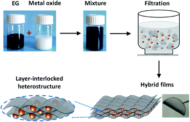 | ||
| Scheme 1 The flow-directed assembly process of EG–metal oxide hybrids and the proposed layer-interlocked structure. | ||
The morphology of the hybrid films was first investigated by SEM with EG–LTO as an example. Spinel LTO NPs with uniform size (∼55 nm) and cubic shape were selected (Fig. S4†). As shown in top-view SEM images of the EG–LTO hybrid (Fig. 1a and b), transparent and crumpled EG nanosheets fully covered the clusters of LTO NPs. The cross-section view images (Fig. 1c and d) evidenced the formation of the layered-interlocked heterostructure throughout the hybrid film, where LTO NPs were well confined between EG nanosheets. The thickness of the compact EG–LTO hybrid film was determined to be ∼17 μm. Further, X-ray photoelectron spectroscopy (XPS) and X-ray diffraction (XRD) measurements conducted on EG–LTO hybrid indicated that both the chemical composition and crystallinity (JCPDS no. 49-0207) of LTO were well preserved during the assembly process (Fig. S5a–e†). The broad peak centered at 26.3° on XRD patterns of EG–LTO derives from few-layer EG sheets. In addition, the sheet resistance of EG–LTO hybrid film with 70 wt% LTO was determined as 143 Ω sq−1, which is 3.7 times the value for pristine EG film (38 Ω sq−1, Fig. S5f†). For comparison, a control sample rGO–LTO was prepared by replacing EG with GO and hydrazine vapor reduction at 100 °C for 8 h (see Experimental section for preparation details). The LTO content in rGO–LTO and thickness of the hybrid films are comparable to EG–LTO. In sharp contrast, the sheet resistance of the rGO–LTO hybrid was as high as 585 Ω sq−1, over 4 times that for EG–LTO.
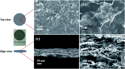 | ||
| Fig. 1 SEM images of EG–LTO hybrid from top view (a and b) and edge view (c and d). Inset is an optical image of the EG–LTO hybrid film. | ||
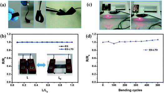
The flexibility of the resultant hybrid films was then investigated in different bending states or after certain bending cycles. Due to the unique layer-interlocked heterostructure, the free-standing EG–LTO hybrid film showed impressive flexibility, which could endure rolling, bending, folding and even twisting (Fig. 2a). Since the resistance of the EG hybrid films could affect their electrochemical performance in Li-ion batteries, the resistance of EG hybrid films under different bending states was evaluated. There was nearly no change in their resistance when the distance between the two ends of EG hybrid films was adjusted from 1 to 0.1 of their original length (Fig. 2b). The bending curvature radius at 0.1L/Lo was around 1 mm. The EG–LTO hybrid film remained electrically conductive to connect a circuit even at a high bending state, similarly to the pure EG film (Fig. 2c and S6†). Furthermore, a resistance increase of only 8% was detected after 500 continuous bending cycles (L/Lo = 0.1–1; Fig. 2d), indicating the high mechanical stability and flexibility of our EG hybrid films.
The co-assembly process plays an important role in the mechanical properties of the resultant EG-based hybrid films. When a mix filtration approach was adopted, the pre-formed stable hybrid dispersion flowed directionally through the filtration membrane, forming a layer-interlocked heterostructure with numerous contact interphases between EG and the guest materials (Fig. S7†). As a consequence, the strong EG hybrid films can be directly peeled off from the filtration membrane. On the contrary, no interlocked structure can be guaranteed by a layer-by-layer (LBL) filtration approach. The formed LBL-hybrid films are fragile along the vertical direction and always fail to be peeled off.
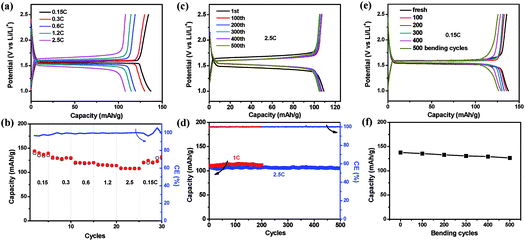
As the fabricated EG–metal oxide hybrid films were flexible, freestanding and conductive, they could be cut into desired shapes and directly used as battery electrodes, where no additional current collector, binder or additive was needed. The electrochemical activity of the EG hybrid films was first evaluated in coin cells with Li foil as the counter electrode. The cyclic voltammetry (CV) curve of the EG–LTO hybrid film is presented in Fig. S8.† A cathodic peak located at 1.47 V (vs. Li/Li+) is ascribed to lithiation of LTO into Li7Ti5O12 (Li4Ti5O12 + 3Li+ + 3e− ⇌ Li7Ti5O12), and an anodic peak at 1.65 V (vs. Li/Li+) corresponds to the delithiation of Li7Ti5O12 back to LTO,36,37 suggesting that the electrochemical performance of EG–LTO hybrid films is mainly derived from the active material LTO. Then we investigated the lithium insertion/extraction properties of the EG–LTO hybrid films by a galvanostatic charge–discharge measurement (Fig. 3). At a small current of 0.15C (1C = 0.14 A g−1), the EG–LTO anode displays a long, flat potential plateau at 1.55 V (vs. Li/Li+) on the discharge curve (Fig. 3a), which is characteristic of a phase transition from LTO to Li7Ti5O12.20 The voltage gap between the charge plateau and the discharge plateau is only 24 mV, indicating negligible polarization. Based on the total mass, the EG–LTO anode delivered a specific capacity of 137 mA h g−1. In light of the LTO content (70 wt%) in the EG–LTO hybrid and its theoretical capacity (175 mA h g−1), LTO should contribute a capacity of 122.5 mA h g−1 to the EG–LTO hybrid. An excess capacity of 14.5 mA h g−1 is ascribed to EG nanosheets in the hybrid. In contrast, the control sample rGO–LTO showed a large voltage gap of 72 mV and an inferior capacity of 125 mA h g−1 at 0.15C (Fig. S9†), which can be attributed to the high resistance of the rGO–LTO hybrid.
Besides, the rate performance of EG–LTO hybrid film was analyzed under accelerated current rates (Fig. 3a and b). When the current increased from 0.15C to 2.5C, slight potential polarization was noticed, accompanied by a capacity decrease from 137 mA h g−1 to 108 mA h g−1. Regarding the charge–discharge curves, the charge–discharge plateaus were retained at all rates, implying highly reversible and fast two-phase equilibrium of EG–LTO.20Fig. 3c and d further show the cycling stability of EG–LTO hybrid films at 1C and 2.5C. After 200 and 500 cycles, the capacity decreased by less than 1.8% of the initial value, demonstrating the excellent electrochemical stability of the freestanding and flexible EG hybrid electrode. The effect of bending on the capacity of EG–LTO hybrid films was also investigated (Fig. 3e and f). Before measuring electrochemical performance at 0.15C, the EG–LTO hybrid films were pre-bent for certain cycles (0, 100, 200, 300, 400 and 500) in the range of 0.1–1 of their original length. We found that after 500 bending cycles, only ∼6% capacity fading was observed, highlighting the remarkable mechanical and electrochemical stability of the formed EG hybrids.
To confirm the structure stability of EG–LTO hybrids, the product morphology of EG–LTO after 100 cycles at 1C was examined by SEM (Fig. S10†). After cycling, a thick polymeric film was formed on the EG–LTO outer surface, which can be assigned to the formed solid-electrolyte interphase (SEI).38 Nevertheless, LTO NPs were still well encapsulated by EG without detachment. From the cross-section view, it was found that the LTO NPs remained confined between EG nanosheets without unexpected aggregation, that is, the layer-interlocked heterostructure was well preserved throughout the electrodes after cycling.
In addition, other flexible EG–metal oxide hybrid films like EG–LCO, EG–LMO and EG–LFP can also be prepared by a similar assembly approach with 90 wt% active materials incorporated (Fig. S11†). EG–LMO and EG–LFP exhibited impressive battery performance (cycling stability and rate performance) as LIB cathodes at potential windows of 3–4.3 V and 3.5–4.0 V (Fig. S12†). For EG–LMO electrodes, two characteristic charge plateaus were observed at 4.0 and 4.15 V. The specific capacity was 106.7 mA h g−1 for the first cycle and 85.3% was retained after 50 cycles at 0.2C (Fig. S12a–c†). The EG–LFP electrodes with a typical discharge plateau at 3.4 V delivered a stable cycling capacity of 80 mA h g−1. No capacity fading was observed after 50 cycles at 0.25C, which can be ascribed to the better structural stability of LFP over LMO during lithiation and delithiation processes (Fig. S12d–f†).
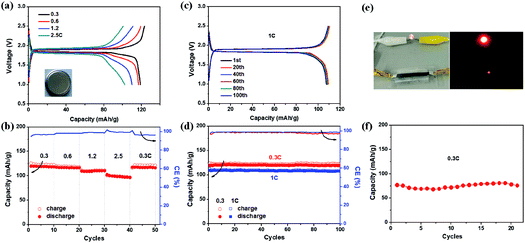
To construct full cells, the EG–LTO hybrid was used as the anode and EG–LFP or EG–LMO hybrid as the cathode. The cathode capacity was kept at 1.2 times the anode capacity,39 and the specific capacity of the entire battery was calculated based on the mass of the EG–LTO hybrid anode. Fig. 4 shows the full cell performance in both coin cells and pouch cells. Typical charge–discharge curves of EG–LTO//EG–LFP full cells present two charge/discharge plateaus around 1.9/1.85 V (Fig. 4a), which are highly consistent with the potential difference between the EG–LFP and EG–LTO electrodes. The full battery exhibited a reversible capacity of 119 mA h g−1 at 0.3C, a little lower than the 130 mA h g−1 for EG–LTO in half cells. Increasing the current rate from 0.3C to 2.5C, slight potential polarization was observed as well and the specific capacity decreased to 100 mA h g−1 (Fig. 4a and b), corresponding to 84% of the capacity at 0.3C. When the current was reversed back to 0.3C, the capacity completely recovered, indicating superb rate performance of EG–LTO//EG–LFP full cells. The cycling performance of EG–LTO//EG–LFP full cells was further investigated at 0.3C and 1C (Fig. 4c and d). After 100 cycles, 99.6% and 98% of the initial capacity was maintained, respectively, demonstrating excellent cycling stability. Similar rate capability and cycling stability were achieved in EG–LTO//EG–LMO full cells, except that the capacity was slightly lower than that in EG–LTO//EG–LFP full cells (Fig. S13†). The areal capacity of the full cells was around 0.5 mA h cm−2 and the energy density of EG–LTO//EG–LFP and EG–LTO//EG–LMO was determined as 80 and 120 W h kg−1, respectively, based on the total mass of both electrodes. To further enhance the energy density of full cells, the Si anode will be explored in the future due to its high theoretical capacity (3579 mA h g−1) and low working potential (<0.25 V vs. Li/Li+). The initial half-cell results indicate that the EG–Si hybrid performed efficiently with a high capacity of 2005 mA h g−1 (Fig. S14†).
Finally, a EG–LTO//EG–LFP pouch cell was assembled with a transparent package and a gel-type solid electrolyte (see Experimental section for preparation details). As shown in Fig. 4e, the cell was able to power a red light-emitting diode (LED). Under 0.3C, the pouch cell delivered a capacity of 75 mA h g−1 after 20 cycles (Fig. 4f). This value is much lower than 119 mA h g−1 for EG–LTO//EG–LFP in coin cells at 0.3C, which can be attributed to the lower ion conductivity of the solid electrolyte used compared to the liquid electrolyte. Due to the use of a solid electrolyte, the demonstration of flexible LIBs at the current stage is not successful. Further optimization of the electrolyte and hybrid composition will be conducted in the future to enhance the electrochemical performance and flexibility of the pouch cell.
In summary, we have demonstrated a straightforward co-assembly approach to prepare flexible EG–metal oxide hybrids for Li-ion batteries. The use of chemically and mechanically stable EG largely simplifies the preparation procedures for flexible electrodes. No metal current collector, binder or other additive was needed. Due to the presence of the unique layer-interlocked heterostructure, the resultant EG hybrids showed high flexibility, mechanical properties and electrochemical performance. When serving as flexible electrodes in LIBs, our EG hybrid films exhibited excellent cycling stability and rate performance in both half cells and full cells. It is worth noting that the co-assembly approach is not limited to particle-like materials. Other dimensional materials like 1D CNTs can also be integrated for EG-based hybrids (Fig. S15†). Our approach may inspire new flexible heterostructure designs based on emerging 2D materials for various energy-related applications.
Conflicts of interest
There are no conflicts to declare.Acknowledgements
This work was financially supported by the ERC grant for HIPER-G (Project ID 768930), the Federal State of Saxony (ESF-Project “GRAPHD”, TU Dresden) and the EC under the Graphene Flagship (GrapheneCore2 785219). The authors acknowledge the CFAED and the Dresden Center for Nanoanalysis (DCN) at TU Dresden.References
- H. Gwon, H.-S. Kim, K. U. Lee, D.-H. Seo, Y. C. Park, Y.-S. Lee, B. T. Ahn and K. Kang, Energy Environ. Sci., 2011, 4, 1277–1283 RSC.
- G. Zhou, F. Li and H.-M. Cheng, Energy Environ. Sci., 2014, 7, 1307–1338 RSC.
- W. Liu, M.-S. Song, B. Kong and Y. Cui, Adv. Mater., 2017, 29, 1603436 CrossRef PubMed.
- L. Wen, F. Li and H.-M. Cheng, Adv. Mater., 2016, 28, 4306–4337 CrossRef CAS.
- H. Kim and J.-H. Ahn, Carbon, 2017, 120, 244–257 CrossRef CAS.
- Y. Hu and X. Sun, J. Mater. Chem. A, 2014, 2, 10712–10738 RSC.
- Y. Huang, M. Zhu, Y. Huang, Z. Pei, H. Li, Z. Wang, Q. Xue and C. Zhi, Adv. Mater., 2016, 28, 8344–8364 CrossRef CAS PubMed.
- M. Armand and J. M. Tarascon, Nature, 2008, 451, 652–657 CrossRef CAS.
- G. Wang, Y. Sun, D. Li, W. Wei, X. Feng and K. Müllen, Small, 2016, 12, 3914–3919 CrossRef CAS PubMed.
- G. Wang, J. Zhang, S. Yang, F. Wang, X. Zhuang, K. Müllen and X. Feng, Adv. Energy Mater., 2018, 8, 1702254 CrossRef.
- L. Hu, J. W. Choi, Y. Yang, S. Jeong, F. La Mantia, L.-F. Cui and Y. Cui, Proc. Natl. Acad. Sci. U. S. A., 2009, 106, 21490–21494 CrossRef CAS PubMed.
- L. Hu, H. Wu, F. La Mantia, Y. Yang and Y. Cui, ACS Nano, 2010, 4, 5843–5848 CrossRef CAS PubMed.
- H. Lin, W. Weng, J. Ren, L. Qiu, Z. Zhang, P. Chen, X. Chen, J. Deng, Y. Wang and H. Peng, Adv. Mater., 2014, 26, 1217–1222 CrossRef CAS.
- Y. Zhang, W. Bai, X. Cheng, J. Ren, W. Weng, P. Chen, X. Fang, Z. Zhang and H. Peng, Angew. Chem., 2014, 126, 14792–14796 CrossRef.
- Y. H. Kwon, S.-W. Woo, H.-R. Jung, H. K. Yu, K. Kim, B. H. Oh, S. Ahn, S.-Y. Lee, S.-W. Song, J. Cho, H.-C. Shin and J. Y. Kim, Adv. Mater., 2012, 24, 5192–5197 CrossRef CAS PubMed.
- Y. Zhang, L. Wang, Z. Guo, Y. Xu, Y. Wang and H. Peng, Angew. Chem., Int. Ed., 2016, 55, 4487–4491 CrossRef CAS PubMed.
- L. Shen, B. Ding, P. Nie, G. Cao and X. Zhang, Adv. Energy Mater., 2013, 3, 1484–1489 CrossRef CAS.
- Q.-C. Liu, J.-J. Xu, D. Xu and X.-B. Zhang, Nat. Commun., 2015, 6, 7892 CrossRef CAS PubMed.
- H. Yu, C. Zhu, K. Zhang, Y. Chen, C. Li, P. Gao, P. Yang and Q. Ouyang, J. Mater. Chem. A, 2014, 2, 4551–4557 RSC.
- N. Li, Z. Chen, W. Ren, F. Li and H.-M. Cheng, Proc. Natl. Acad. Sci. U. S. A., 2012, 109, 17360–17365 CrossRef CAS PubMed.
- R. Mo, D. Rooney, K. Sun and H. Y. Yang, Nat. Commun., 2017, 8, 13949 CrossRef CAS PubMed.
- T. Jiang, F. Bu, X. Feng, I. Shakir, G. Hao and Y. Xu, ACS Nano, 2017, 11, 5140–5147 CrossRef CAS PubMed.
- Y. Chao, R. Jalili, Y. Ge, C. Wang, T. Zheng, K. Shu and G. G. Wallace, Adv. Funct. Mater., 2017, 27, 1700234 CrossRef.
- K. Parvez, Z.-S. Wu, R. Li, X. Liu, R. Graf, X. Feng and K. Müllen, J. Am. Chem. Soc., 2014, 136, 6083–6091 CrossRef CAS PubMed.
- S. Yang, S. Brüller, Z.-S. Wu, Z. Liu, K. Parvez, R. Dong, F. Richard, P. Samorì, X. Feng and K. Müllen, J. Am. Chem. Soc., 2015, 137, 13927–13932 CrossRef CAS PubMed.
- Y. Xu, K. Sheng, C. Li and G. Shi, ACS Nano, 2010, 4, 4324–4330 CrossRef CAS PubMed.
- G. Wang, L.-T. Jia, Y. Zhu, B. Hou, D.-B. Li and Y.-H. Sun, RSC Adv., 2012, 2, 11249–11252 RSC.
- G. Wang, L.-t. Jia, B. Hou, D.-b. Li, J.-g. Wang and Y.-h. Sun, New Carbon Mater., 2015, 30, 30–40 CrossRef CAS.
- T.-T. Shan, S. Xin, Y. You, H.-P. Cong, S.-H. Yu and A. Manthiram, Angew. Chem., 2016, 128, 12975–12980 CrossRef.
- K. R. Paton, E. Varrla, C. Backes, R. J. Smith, U. Khan, A. O’Neill, C. Boland, M. Lotya, O. M. Istrate, P. King, T. Higgins, S. Barwich, P. May, P. Puczkarski, I. Ahmed, M. Moebius, H. Pettersson, E. Long, J. Coelho, S. E. O’Brien, E. K. McGuire, B. M. Sanchez, G. S. Duesberg, N. McEvoy, T. J. Pennycook, C. Downing, A. Crossley, V. Nicolosi and J. N. Coleman, Nat. Mater., 2014, 13, 624 CrossRef CAS PubMed.
- I. K. Moon, J. Lee, R. S. Ruoff and H. Lee, Nat. Commun., 2010, 1, 73 CrossRef PubMed.
- D. A. Dikin, S. Stankovich, E. J. Zimney, R. D. Piner, G. H. B. Dommett, G. Evmenenko, S. T. Nguyen and R. S. Ruoff, Nature, 2007, 448, 457–460 CrossRef CAS PubMed.
- H. Chen, M. B. Müller, K. J. Gilmore, G. G. Wallace and D. Li, Adv. Mater., 2008, 20, 3557–3561 CrossRef CAS.
- Y. Hernandez, V. Nicolosi, M. Lotya, F. M. Blighe, Z. Sun, S. De, I. T. McGovern, B. Holland, M. Byrne, Y. K. Gun’Ko, J. J. Boland, P. Niraj, G. Duesberg, S. Krishnamurthy, R. Goodhue, J. Hutchison, V. Scardaci, A. C. Ferrari and J. N. Coleman, Nat. Nanotechnol., 2008, 3, 563–568 CrossRef CAS PubMed.
- D. Li, M. B. Müller, S. Gilje, R. B. Kaner and G. G. Wallace, Nat. Nanotechnol., 2008, 3, 101 CrossRef CAS PubMed.
- M. Odziomek, F. Chaput, A. Rutkowska, K. Świerczek, D. Olszewska, M. Sitarz, F. Lerouge and S. Parola, Nat. Commun., 2017, 8, 15636 CrossRef CAS PubMed.
- S. Mao, X. Huang, J. Chang, S. Cui, G. Zhou and J. Chen, NPG Asia Mater., 2015, 7, e224 CrossRef CAS.
- Y.-B. He, B. Li, M. Liu, C. Zhang, W. Lv, C. Yang, J. Li, H. Du, B. Zhang, Q.-H. Yang, J.-K. Kim and F. Kang, Sci. Rep., 2012, 2, 913 CrossRef PubMed.
- W. Weng, Q. Sun, Y. Zhang, S. He, Q. Wu, J. Deng, X. Fang, G. Guan, J. Ren and H. Peng, Adv. Mater., 2015, 27, 1363–1369 CrossRef CAS PubMed.
Footnote |
| † Electronic supplementary information (ESI) available. See DOI: 10.1039/c9fd00120d |
| This journal is © The Royal Society of Chemistry 2021 |

