 Open Access Article
 This Open Access Article is licensed under a
 Creative Commons Attribution 3.0 Unported Licence
Core–shell graphene oxide–polymer hollow fibers as water filters with enhanced performance and selectivity†
Alessandro
Kovtun‡
 a,
Antonio
Bianchi‡
a,
Massimo
Zambianchi
a,
Cristian
Bettini
a,
Franco
Corticelli
b,
Giampiero
Ruani
c,
Letizia
Bocchi
d,
Francesco
Stante
e,
Massimo
Gazzano
a,
Tainah Dorina
Marforio
f,
Matteo
Calvaresi
f,
Matteo
Minelli
g,
Maria Luisa
Navacchia
a,
Vincenzo
Palermo
*ah and
Manuela
Melucci
*a
a,
Antonio
Bianchi‡
a,
Massimo
Zambianchi
a,
Cristian
Bettini
a,
Franco
Corticelli
b,
Giampiero
Ruani
c,
Letizia
Bocchi
d,
Francesco
Stante
e,
Massimo
Gazzano
a,
Tainah Dorina
Marforio
f,
Matteo
Calvaresi
f,
Matteo
Minelli
g,
Maria Luisa
Navacchia
a,
Vincenzo
Palermo
*ah and
Manuela
Melucci
*a
aConsiglio Nazionale delle Ricerche-Institute of Organic Synthesis and Photoreactivity (CNR-ISOF), via Piero Gobetti 101, 40129 Bologna, Italy. E-mail: manuela.melucci@isof.cnr.it; vincenzo.palermo@isof.cnr.it
bConsiglio Nazionale delle Ricerche-Institute for Microelectronics and Microsystems, (CNR-IMM), via Piero Gobetti 101, 40129 Bologna, Italy
cConsiglio Nazionale delle Ricerche-Institute of Nanostructured Materials (CNR-ISMN), via Piero Gobetti 101, 40129 Bologna, Italy
dMedica spa, via degli Artigiani 7, 41036 Medolla, MO, Italy
eStante Laboratories, Via del Chiù 68-70, Bologna, Italy
fAlma Mater Studiorum – University of Bologna, Department of Chemistry ‘G. Ciamician’, via Selmi 2, 40129 Bologna, Italy
gAlma Mater Studiorum – University of Bologna, Department of Civil, Chemical, Environmental and Materials Engineering (DICAM), via Terracini, 28 40131 Bologna, Italy
hChalmers University of Technology, Industrial and Materials Science, Hörsalsvägen 7A, SE-412 96 Göteborg, Sweden
First published on 23rd January 2020
Abstract
Commercial hollow fiber filters for micro- and ultrafiltration are based on size exclusion and do not allow the removal of small molecules such as antibiotics. Here, we demonstrate that a graphene oxide (GO) layer can be firmly immobilized either inside or outside polyethersulfone–polyvinylpyrrolidone hollow fiber (Versatile PES®, hereafter PES) modules and that the resulting core–shell fibers inherits the microfiltration ability of the pristine PES fibers and the adsorption selectivity of GO. GO nanosheets were deposited on the fiber surface by filtration of a GO suspension through a PES cartridge (cut-off 0.1–0.2 μm), then fixed by thermal annealing at 80 °C, rendering the GO coating stably fixed and unsoluble. The filtration cut-off, retention selectivity and efficiency of the resulting inner and outer modified hollow fibers (HF-GO) were tested by performing filtration on water and bovine plasma spiked with bovine serum albumin (BSA, 66 kDa, ≈15 nm size), monodisperse polystyrene nanoparticles (52 nm and 303 nm sizes), with two quinolonic antibiotics (ciprofloxacin and ofloxacin) and rhodamine B (RhB). These tests showed that the microfiltration capability of PES was retained by HF-GO, and in addition the GO coating can capture the molecular contaminants while letting through BSA and smaller polystyrene nanoparticles. Combined XRD, molecular modelling and adsorption experiments show that the separation mechanism does not rely only on physical size exclusion, but involves intercalation of solute molecules between the GO layers.
Introduction
The development of novel membrane materials for purification of fluids is of great interest for the fabrication of personalized biomedical treatments (i.e. selective apheresis, dialysis), specific chemical separation (organic solutes from organic matrices), advanced water purification1 and gas separation technologies.2Polymeric membranes are currently exploited at the industrial level for a variety of processes and applications, spanning blood filtration to food/drug purification, and drinking and wastewater purification.3
The market trend for polymeric membrane filtration modules is growing, and it is expected to further increase in the next few years due to the increasing demand for advanced healthcare treatments and also drinkable water. In general, polymeric membrane filtration modules may be classified into three types, namely plate and frame, spiral wound, and hollow fiber (HF) modules. Among them, hollow fiber modules are the most used as separation units in industry because of their unique characteristics of self-support, high membrane packing density, and high surface/volume ratio.4 Compared to planar membranes, the hollow-fiber configuration has a much larger membrane area per unit volume of membrane module. The surface to volume ratio is about 300–500 m2 m−3 for plate and frame modules, 600–800 m2 m−3 for spiral wound modules, and 6000–13![[thin space (1/6-em)]](https://www.rsc.org/images/entities/char_2009.gif) 000 m2 m−3 for hollow fiber modules, resulting in higher productivity. Nowadays, hollow fiber configurations are widely used in basically all types of membrane separation, including gas separation, ultrafiltration, pervaporation, dialysis and supported liquid membrane extraction.
000 m2 m−3 for hollow fiber modules, resulting in higher productivity. Nowadays, hollow fiber configurations are widely used in basically all types of membrane separation, including gas separation, ultrafiltration, pervaporation, dialysis and supported liquid membrane extraction.
The filtration mechanism of these membranes mainly relies on size exclusion, and the pore size ultimately defines the cut-off range. Microfiltration is widely used in water treatment and plasma apheresis as a disinfection step since colloidal particles, microorganisms and other particulate material of a size larger than about 200 nm are removed. Ultrafiltration and nanofiltration membrane modules have higher cut-offs of 1–10 nm and 100–200 nm, respectively, thus enabling decontamination of viruses/endotoxins (ultrafiltration) and low molecular weight molecules (nanofiltration), but the throughput is much lower than what is achievable for microfiltration.
However, there is an urgent market and societal need to improve the removal of emerging organic contaminants (EOC) such as pesticides, pharmaceuticals, or surfactants used in large quantities in civil industrial and farming activities, which are able to contaminate water sources or food and liquids, causing severe environmental and health problems.
Recently, membrane doping with nanomaterials has been reported as a promising strategy to tune the selectivity and enhance the efficiency of polymeric membranes.5 Among nanomaterials, graphene oxide (GO) is particularly suitable for promoting selective recognition processes due to its intrinsic 2-D configuration, high surface area and abundance of surface chemical groups. For instance, the addition of a small amount of GO in polysulfone-based membranes obtained by phase inversion increased their hydrophilicity and antimicrobial activity, reduced the biofouling,6 promoted arsenate rejection,7 and allowed for oil–water separation.8 In general, graphene containing membranes are receiving increasing attention because they exhibit enhanced separation performance with enormous potential outcomes for ion sieving, desalination and water purification applications.9–12
Graphene oxide also has excellent adsorption properties toward EOC (including pharmaceuticals and personal care products)13–16 and metal ions, even at very low concentration.17 This feature has led to the development of 3D structures with removal efficiencies superior to those of other nanomaterial-based adsorbents including Granular Activated Carbon (GAC), the industrial standard, for some metal ions and organic compounds. Moreover, covalent chemical modification of the oxygen-based functionalities of GO allows tuning of the adsorption selectivity of GO-based structures.18 In this direction, enhanced adsorption of heavy metal ions and organic dyes in water and wastewater have been reported for EDTA,19 sulfonated20 and amino-rich21 graphenes.
Aiming to exploit both the adsorption properties and membrane enhancing effects of GO to develop new multifunctional filters, we recently demonstrated the superior efficiency of GO-doped polysulfone porous structures toward hydrophilic organic contaminants including dyes and drugs.22 We also described a simple method to fix GO on scraps from the production of polysulfone (PSU) ultrafiltration membranes.23 The process involves the partial removal under vacuum of water from a GO and PSU suspension, followed by thermal fixation.24 This material showed enhanced removal capability (up to seven times) toward polar organic contaminants (e.g. ofloxacin and rhodamine B) thanks to the high hydrophilicity of the GO layer exposed to the surface in contact with water. The coating process allows GO to be fixed on the PS surface by means of supramolecular interactions, by exploiting the spontaneous aggregation of GO sheets on PSU and enabling up to 50% of the PSU total surface area to be covered. The filter could effectively capture EOC, but poor retention was obtained for larger chemical moieties with respect to hollow fiber-based ultrafiltration cartridges.
Typically, polymer composites containing graphene or GO are prepared by mixing or co-extrusion, then shaped in the final form. GO or graphene could in some cases be applied on the surface of simple shapes, such as powders24 or flat sheets;25 until now, it has however never been possible to apply GO coatings on the surface of finite commercial devices such as filters.
We thus developed a completely different approach, exploiting the filtration capability of commercial hollow fiber filters to achieve a uniform coating on a geometrically complex substrate. We could thus obtain GO coatings on polyethersulfone–polyvinylpyrrolidone hollow fibers (HF) made of a commercial polymer, Versatile PES® (Fig. 1a–d), already assembled in a working filter cartridge (commercial name ‘Plasmart’). Then, we used these filters for purification of water solutions and showed the possibility to selectively remove small molecules (including two antibiotics of current environmental concern).
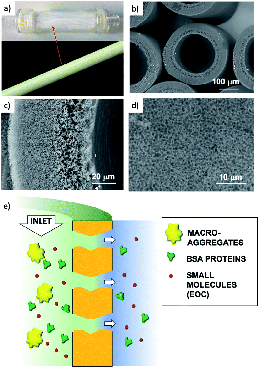 | ||
| Fig. 1 (a) Versatile PES® hollow fiber filtration cartridge (lab. scale prototype 10 cm length (Plasmart 25, Medica)) and single fiber. In the cartridge the edges of the fiber capillaries are sealed by an epoxy resin. (b) Fibers, (c) cross-section, (d) detail of the outer wall pores. (e) Cartoon of filtration through the cartridge (in–out). | ||
Stable coating of the outer or inner walls of PES hollow fibers with a GO membrane and controlled membrane thickness was achieved by filtration of a GO suspension in dead-end configuration (Fig. 2), followed by thermal fixation by annealing in an oven.
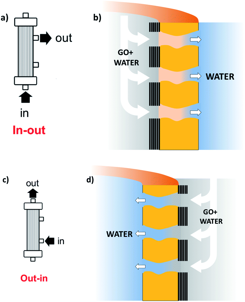 | ||
| Fig. 2 Sketch of the coating procedure. (a) and (b) Filtration in–out to immobilize GO on the inner fiber wall; (c) and (d) filtration out–in to immobilize GO on the outer fiber wall. Different GO% amounts (1, 5, 10%) can be achieved by reiteration of the filtration/thermal fixation procedure. Partial fiber pore coverage and GO penetration are omitted for simplicity (see details in Fig. 4, and S4 and S5, ESI†). | ||
The retained microfiltration capability was assessed for HF-GO by filtering a mixture containing:
(1) Nanoscopic objects of different sizes: protein (Bovine Serum Albumin, BSA, Mw = 66 kDa) and polystyrene beads (52 nm and 303 nm sizes);
(2) molecular EOC contaminants. As realistic test molecules we chose ofloxacin and ciprofloxacin (two quinolonic antibiotics under monitoring by the EU) and rhodamine B (a textile dye, Fig. S1, ESI†).
Results and discussion
GO immobilization and fixation
Graphene oxide powder (<35 mesh, purchased from Abalonyx, sheet lateral size about 1 μm, many primary single sheets declared) was suspended in Milli-Q water (2 mg mL−1) and sonicated for 4 hours. Then, the GO solution was filtered through commercial HF filters (Plasmart 25, Medica). Each filter was composed of ca. 275 PES fibers, with each fiber having a length of ca. 4.5 cm, an inner diameter of ≈280–300 μm and an outer diameter of ≈360–400 μm. Thanks to the approach used, we could choose to coat the inner surface of the HF (Fig. 2a) or the outer surface (Fig. 2c), using two different dead-end filtration modalities. After filtration of 5 mL of solution containing about 10 mg of GO, the cartridges were kept in oven at 80 °C overnight to give HF-GO1i samples, i.e. hollow fibers containing about 1% w/w of GO with respect to the PES membrane weight in the inner surface. Hereafter, we will name samples as HF-GO followed by the % of GO loading and the letter e/i, indicating whether the coating is placed on the outer or inner surface of the hollow fiber. Following this nomenclature, we repeated the filtration–fixation cycle to obtain samples HF-GO1e/i, HF-GO5e/i and HF-GO10e/i, varying the coating from about 1% to 5% and 10%, either on the inner or outer surface.The HF-GO filters are shown in Fig. 3. For fibers coated on the outside wall, the dark color of the coating is clearly visible by increasing the amount of GO loading from 1% to 10%. Fibers with inside GO coating showed no apparent change of colour (Fig. 3b), but a black coating could be observed in the inner wall by cutting the fibers (Fig. 3d).
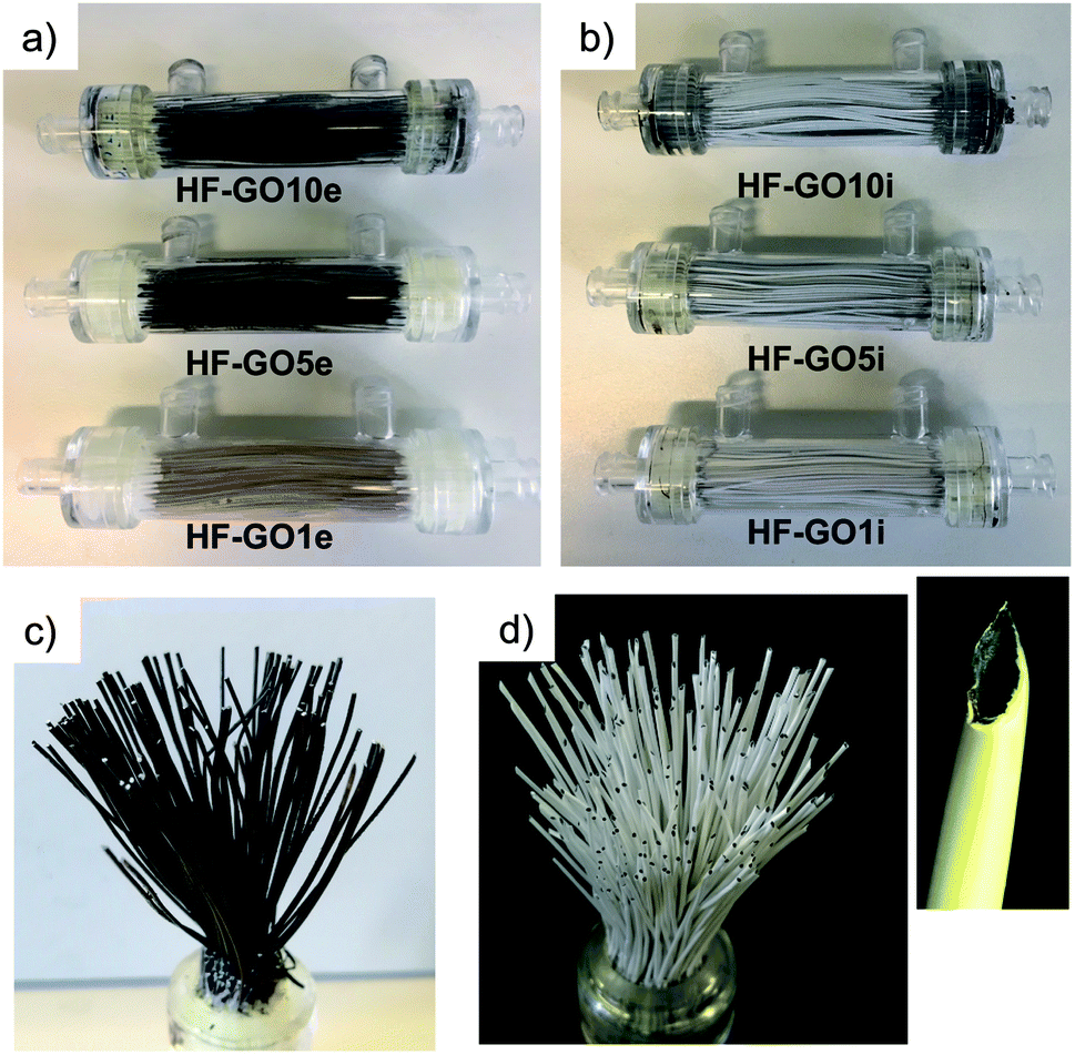 | ||
| Fig. 3 (a) Cartridges (10 cm length) of HF-GOe and (b) HF-GOi at GO loading of 1, 5, 10% (w/w). Bundle of (c) HF-GO5e and (d) HF-GO5i; the inset shows a single inner coated fiber. | ||
The stability of the GO membrane coating was tested by flowing deionized water (1 L) through the cartridges before and after thermal fixation and by performing UV-vis absorption spectroscopy on the filtered water, comparing the results to what was obtained with calibrated solutions of GO at known concentrations (Fig. S2, ESI†). No evidence of GO nanosheets was found in the filtered water (detection limit 2–5 ppm, Fig. S2, ESI†), confirming that the fixation process we already used on the powders is effective on the hollow fibers as well.24 We also performed standard chemical potability tests (certified analysis of salts, metal ions, taste, total organic carbon) on tap water filtered through HF-GO5e/i cartridges, confirming the potability of the filtered water and the absence of any dangerous contaminants, in accordance with current legal limits (D. Lgs. 31/01 Agg. D.M. 14/06/2017, Table S1, ESI†).
Membrane characterization
A combination of optical microscopy, SEM and micro-Raman analyses was carried out to investigate the homogeneity of the coating, while XRD measurements were performed to estimate the periodic stacking in the GO coatings in HF-GO fibers and the number of GO layers. Optical microscopy on the HF-GO fibers (Fig. 4a and S3, ESI†) showed a black coating on the whole fiber surface. GO coating was not uniform at the lowest GO load (1%), while uniform coating was found for all the other samples. Accordingly, SEM analysis on HF-GOe fibers (Fig. 4b and c) showed the presence of a GO layer covering the fiber surface. Fig. 4b shows the case of HF-GO5e. Notably, some open (uncoated) pores (about 1 μm size) were also observed (Fig. 4c and S4, ESI†). This is highly beneficial, since it ensures that the membrane is not clogged due to GO coating. Micro-Raman analysis performed on HF-GO1e and HF-GO10e (Fig. S5, ESI†) showed a limited infiltration depth of GO within the fiber pore channels independent of the amount of GO used for coating. Indeed, in both outer modified HF, at 5 μm from the GO layer on the outer surface wall it was possible to detect Raman peaks of GO that completely disappeared in the bulk of the fiber section (at about 25 μm from the external wall, Fig. S5, ESI†).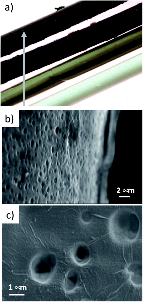 | ||
| Fig. 4 (a) Fibers of PES and HF-GOe 1–5–10%. (b) HF-GO5e, representative SEM image of a GO coating on the outer fiber wall. (c) Detail of the coating of HF-GO10e fibers. SEM images of all samples at different magnifications are reported in ESI (Fig. S4, ESI†). | ||
Fig. 5a shows the XRD patterns of HF-GO fibers. The bell-shaped profiles centred at 18.1° (2-theta) were due to the amorphous PES component. A signal due to the stacked GO nanosheets was observed at about 11.7° (d = 0.75 nm), visible as a shoulder or peak depending on the GO loading, and better evidenced after data treatment (Fig. 5b). This distance is slightly smaller than that calculated for the pristine GO powder (10.5°, d = 0.84 nm), and was ascribed to partial dehydration during the annealing treatment.24 The thickness of the stacked crystalline domains was estimated from peak width using the Scherrer equation.25 The stacked domains of GO had an average thickness of 6–8 layers on all observed fibers, indicating that even thicker coatings do not form a continuous, perfectly stacked layer (Fig. 5c and Table S2, ESI†). Rather, the coating is formed by a number of these crystalline nanometre sized regions assembled together in a compact structure of different thicknesses.
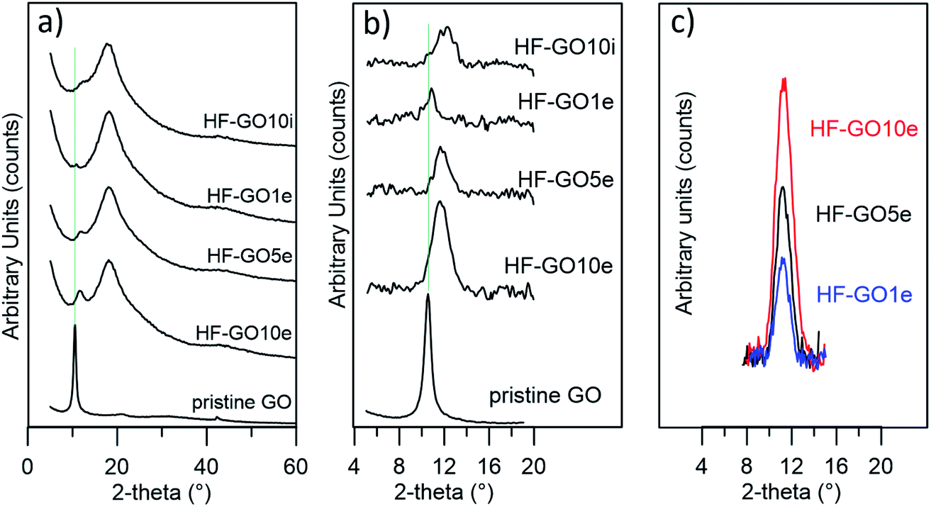 | ||
| Fig. 5 (a) XRD patterns of HF-GO fibers and GO powder; (b and c) direct comparison of GO peaks. To allow a more direct comparison, in (b and c) the XRD signal due to background and polymer has been subtracted and in (c) a shift on the 2-theta scale was also applied. | ||
Filtration selectivity and efficiency
Water permeability tests were firstly performed on HF-GO cartridges in the same dead-end configuration described in the experimental part. Each cartridge was filled with osmotic water, the pressure value was measured at the filter inlet, the amount of water microfiltered in 1 minute was weighed and the filtration coefficient (Kf) was calculated. As expected, the permeability of PES decreased as long as the amount of GO loading increased. We observed the lowest Kf of 0.42 ± 0.24 mL min−1 mmHg−1 m−2 for the HF coated with 10% GO on the outside. The ideal Kf for filtering tests was obtained for inside coatings of 1% and 5% (Fig. 6).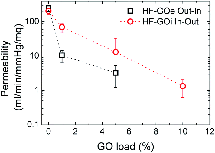 | ||
| Fig. 6 Water permeability response for HF-GO e/i at different GO loads. Filtration was performed by flowing water first across the GO layer (i.e. in–out for HF-GOi and out–in for HF-GOe). | ||
Besides measuring the permeability of water, we also measured (dry) air permeability, in order to distinguish the contribution of water transport across swollen GO or polymer with respect to the transport in macroscopic pores.26 The obtained air permeability measured confirmed the porous structure of the HF, revealing an incomplete coating of the PES HF at the lowest GO concentration, thus featuring several holes; for thicker coatings, a complete impermeable coating could also not be detected, even though a significantly more compact structure was obtained, and the diffusing molecules have to proceed along a very tortuous path to cross coating, wiggling around the GO layers (see ESI, Fig. S6 for more details†).
The cut-off of the PES hollow fiber pores used is in the range 0.1–0.2 μm, optimal for microfiltration of biological samples, blocking colloids and microorganisms of size >1.000 kDa (Fig. S7 and S8 ESI†). To establish the cut-off of the HF-GO fibers, filtration tests were performed on water spiked with BSA and polystyrene standard nanoparticles with sizes below and above the cut-off of PES cartridges (i.e. PS NPs, 52 nm and 303 nm sizes). BSA (about 15 nm, 66 kDa) and 52 nm PS NPs are expected to cross a microfiltration membrane, while 303 nm sized PS NPs are expected to be retained. Fig. 7 shows that all filters blocked larger particles and let through smaller ones, as expected, and the retention of 52 nm PS NPs was basically equal to that of the bare HF modules (about 20%). This indicates that no clogging effect of GO occurred and that there were pores in the range 52–303 nm available for filtration.
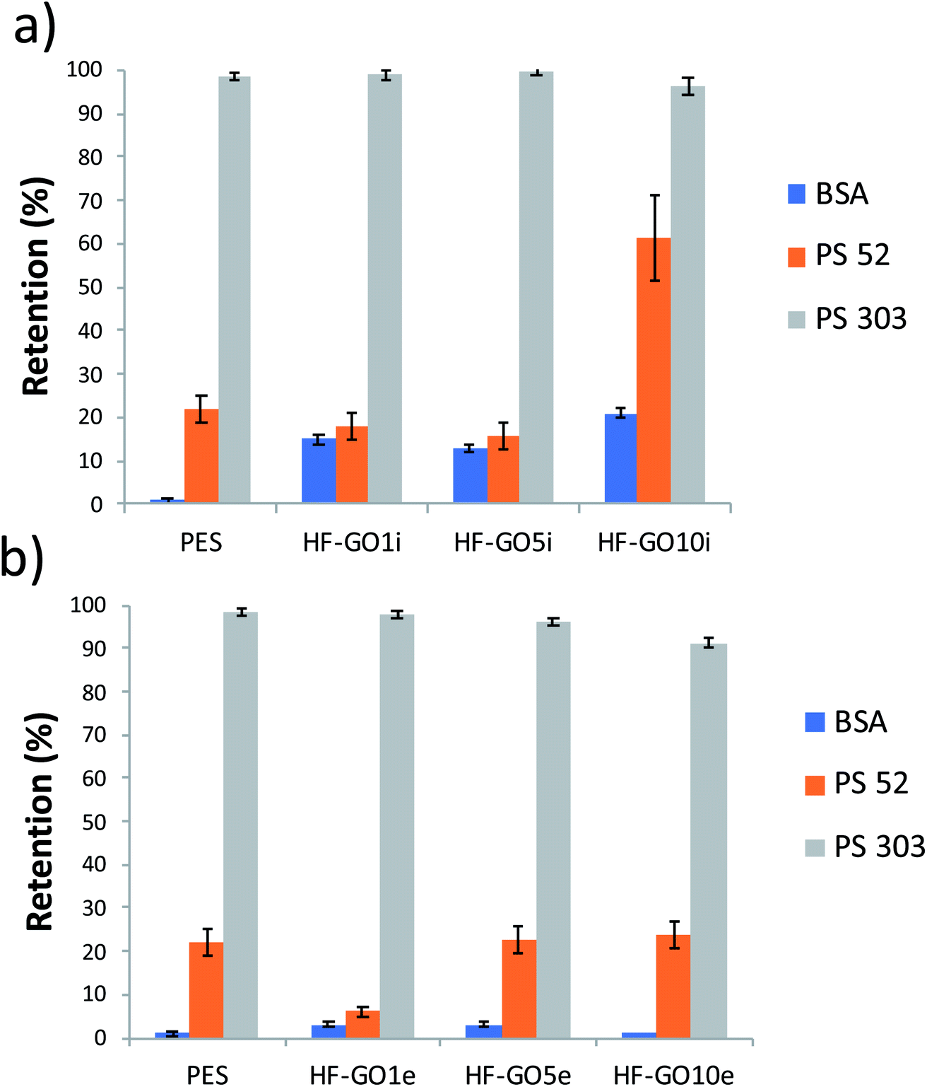 | ||
| Fig. 7 HF-GOi (a) and HF-GOe (b) retention efficiency of BSA, PS 52 and PS 303 from water solution. HF-GO behaved as commercial PES modules, i.e. they retained large PS NPs. | ||
A partial retention of BSA was observed in the HF-GOi membranes (up to 15–20%), while no significant effect was detected from the cartridges with GO coatings on the external surface. This can hardly be attributed to a size exclusion mechanism, and effective nanofiltration operation was excluded, in view of the smaller size of BSA with respect to 52 nm PS NPs. Additional BSA and filtration experiments are reported in the ESI (Fig. S7 and S8,† respectively).
Once we verified that the GO coating does not affect the size-dependent filtering performance of the filters, we measured their ability to retain, instead, small contaminant molecules (RhB, OFLOX and ciprofloxacin, 5 mg L−1 in water), which cannot be blocked by the standard filters due to their nanometric size, which is much smaller than BSA protein.
We measured the removal efficiency of the filters for such molecular contaminants by fluxing through the filter 250 mL of solutions contaminated with each molecule (5 mg L−1) at 15 mL min−1, then analysing the filtered solution by HPLC/UV analysis (details in ESI†).
Uncoated PES filters (GO load 0%) showed insignificant filtering effects for the standard contaminants inspected, as shown in Fig. 8, with removal efficiencies <10% in all cases. Conversely, HF-GO fibers showed significant removal ability, up to about 80% in the best case (Ciproflox filtered by HF-GO10i). Removal performance increased with GO loading, showing a monotonous increase for the outer-coated fibers (Fig. 8a), and a saturation plateau for the inner-coated ones (Fig. 8b). The best performances were reached with a lower amount of GO in inner-coated fibers, which showed a significant removal performance even at low GO loading, i.e. removing 50% of Ciproflox vs. about 20% for outer-coated fibers at 1% GO loading. At the highest loadings (GO 10% w/w), the performances of the two filters (inner or outer coatings) are equivalent.
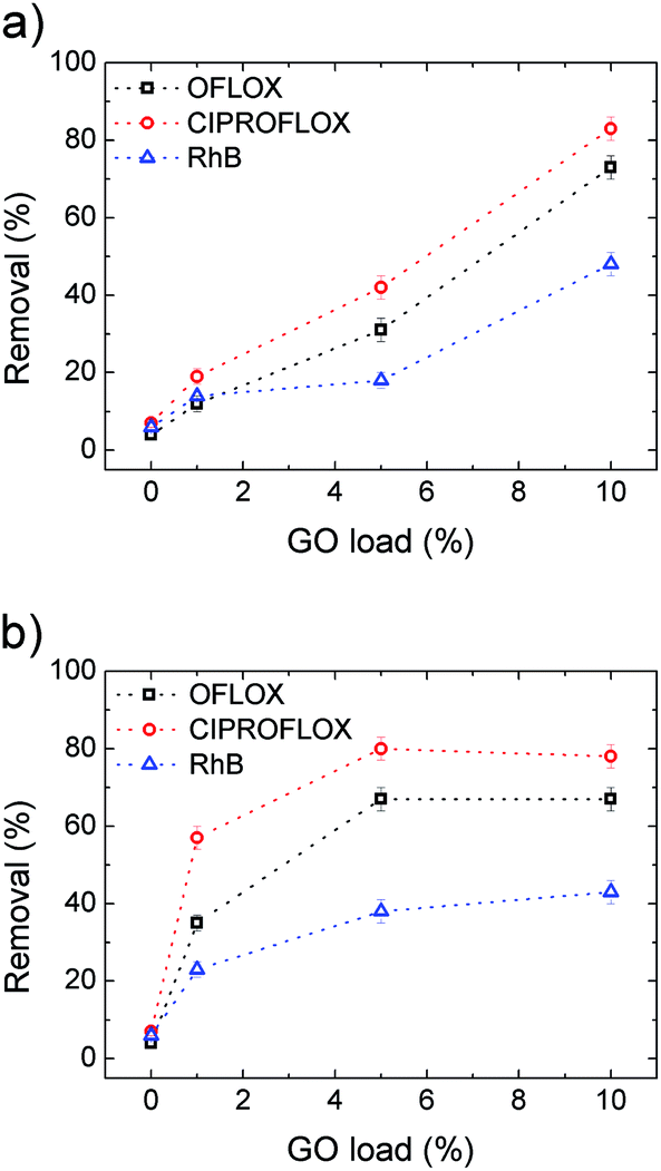 | ||
| Fig. 8 Removal efficiency for OFLOX, Ciproflox and RhB vs. GO loading for (a) HF-GOe and (b) HF-GOi. The concentration (5 mg L−1), flow (15 mL min−1) and fluxed volume (250 mL) of the contaminant solutions were the same for all tests. Filtration was performed by flowing water firstly passing through the GO layer, i.e. in–out for inner coated fibers and out–in for outer coated fibers. | ||
Therefore, the mechanism of capture of these substances does not rely on size exclusion, but it rather is given by adsorption onto the GO layer surface, which is able to interact with such molecules. The larger the GO amount on the HF module, the larger the EOC removal. The key aspect of the filtration step is the accessibility of the adsorbing sites in the GO layer, thus allowing these molecules to be intercalated. The more open structure of inner coated filters, as indicated by both water and air permeability tests (Fig. 6 and S6, ESI† respectively), and their larger porosity promote contaminant transport in the coating with more effective contact with the adsorbing sites.
Previous experiments confirmed that small quantities of GO can capture hundreds of mg of OFLOX and RhB (isotherms), ca. 590 mg g−1 for RhB and 360 mg g−1 for OFLOX, but such experiments were always performed in static configuration, with a prolonged (24 h) contact time between GO and the contaminant solution. Kinetics studies of EOC removal showed how equilibrium conditions can be achieved after different times, 5–10 minutes for RhB27 and 60–80 minutes for OFLOX;28 such a timescale is incompatible with continuous flow filtering, for practical applications.
In our setup, with a 15 mL min−1 flow and 2.5 mL cartridge volume, the contact time is ≈10 seconds, thus indicating that the operative conditions of the filters are very far from thermodynamic equilibrium. However, we could achieve significant removal even if our contact time was one order of magnitude smaller than what is reported in the above cited works. We attribute this remarkable performance to the synergic action of the fiber pores and the GO coating, with the solution being forced to pass through the GO coating (see scheme in Fig. 2), thus in an ideal condition for the intercalation and trapping of the EOC molecules in between overlapped GO layers in the GO layers, as described in previous work.24
After demonstrating the improved performance of the HF-GO filters compared to standard PES, we also calculated the filter longevity, i.e. the ability to filter significant amounts of solution before having to be replaced. The concentration of EOC pollutants is usually in the sub ppb range, thus we estimated our filter consumption using a contaminant concentration of 0.2 μg L−1 for Ciproflox. Fig. 9 shows the removal efficiency of the filters as a function of cumulative mass fluxed. This plot allows us to estimate the amount of Ciproflox removed by a single cartridge and normalise the removed EOC mass on the mass of the active material (GO). We see that HF-GO5i can have a reasonable removal of about 90% with 15 mg gGO−1 of Ciproflox, 14 mg gGO−1 of OFLOX and 7 mg gGO−1 of RhB. This is not the adsorbed amount at equilibrium at high concentration, but the effective amount of EOC adsorbed by the operative filter. It is remarkable that such values are obtained with quite a short contact time (seconds), while the references in water treatment plants are usually 10–20 minutes, with ca. 20 μg g−1 of Ciproflox removed by using traditional powdered activated carbon.29 In turn, the filter HF-GO5i still has a removal efficiency ca. 90% after the flow of a total mass of 0.5 mg of contaminant, corresponding to ca. 2500 L of realistic contaminated solution with 0.2 ppb of Ciproflox; this proves the suitability of HF-GO filters for realistic commercial applications (see also Table S7, ESI†).
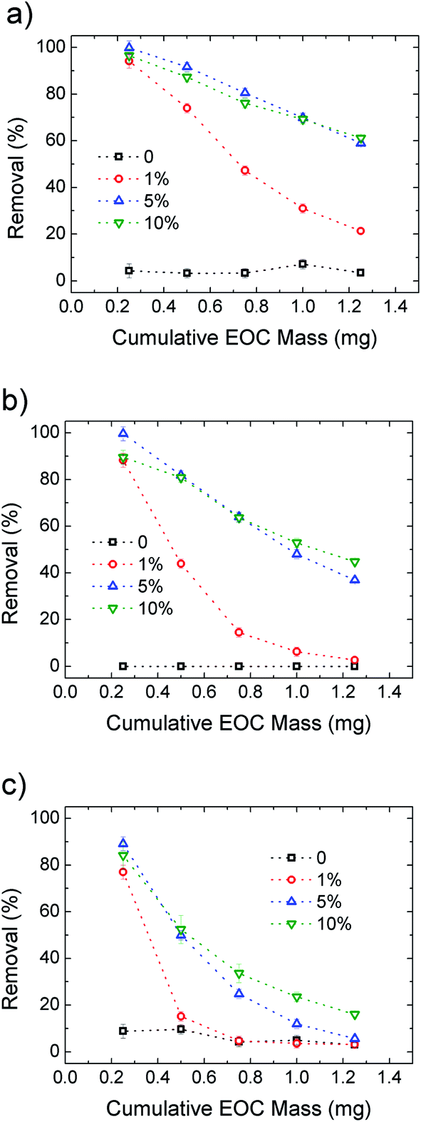 | ||
| Fig. 9 Removal efficiency for Ciproflox (a), OFLOX (b) and RhB (c) for PES and increasing GO loading in HF-GOi. The cumulative initial mass is obtained with fixed concentration (5 mg L−1) and flow (15 mL min−1). Details are reported in Fig. S10. The curves for HF-GOe filters are shown in Fig. S11, ESI.† | ||
Fig. 9 compares the removal efficiency of inner coated HF-GOi filters toward the three EOC molecules. As expected, the filters are rapidly saturated with only 1% GO loading, while 5% and 10% loading give the best performances, in particular for Ciproflox, while RhB gives the worst longevity performance in all cases.
Simultaneous filtration and adsorption test and working mechanism
Eventually, we performed filtration of a complex, realistic matrix of BSA and OFLOX solution, to confirm the capability of HF-GO filters to work simultaneously as a physical filter (cut-off depending on the pore size) and adsorbent (mediated by chemical interactions). The filtration tests were performed with both water (Fig. 10) and bovine plasma matrices (Fig. S8 and S12, ESI†). As a representative case study, in Fig. 10 we show a HF-GOi filter that features almost quantitative removal of OFLOX (≈90%) and negligible (<1%) removal of BSA. Similar results were found in bovine plasma matrix containing BSA and other proteins with a total concentration of about 6–8 g dL−1, with no significant reduction of the BSA and TP amounts occurring after filtration (Fig. S13, ESI†).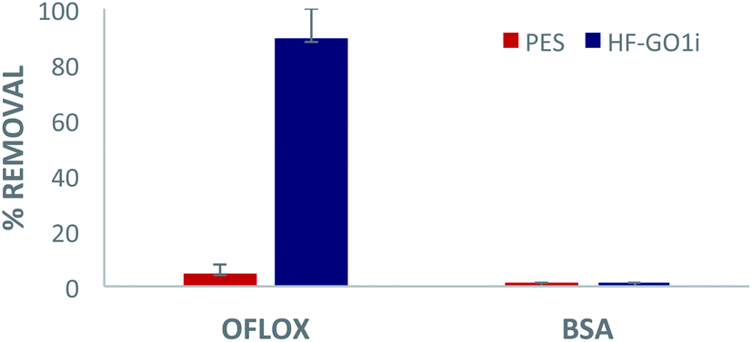 | ||
| Fig. 10 Filtration of tap water spiked with 50 mg L−1 of ofloxacin and 10 g L−1 of BSA. Quantification by HPLC-UV analysis. | ||
The mechanism of filtration was investigated by XRD analysis (Fig. 11a). We extracted the fibers from the filters after filtration of the contaminated solutions, and estimated GO stacking using XRD, comparing them with pristine, unused fibers. We observed a shift of the GO peak towards a larger stacking distance after filtration of EOC (0.75 nm → 0.89 nm), and a decrease in intensity. This suggests that the removal mechanism is due to the strong affinity between the aromatic core of the EOC with the sp2 structure of the GO layers that induces partial swelling and exfoliation of the layers, as discussed in detail in previous work.24
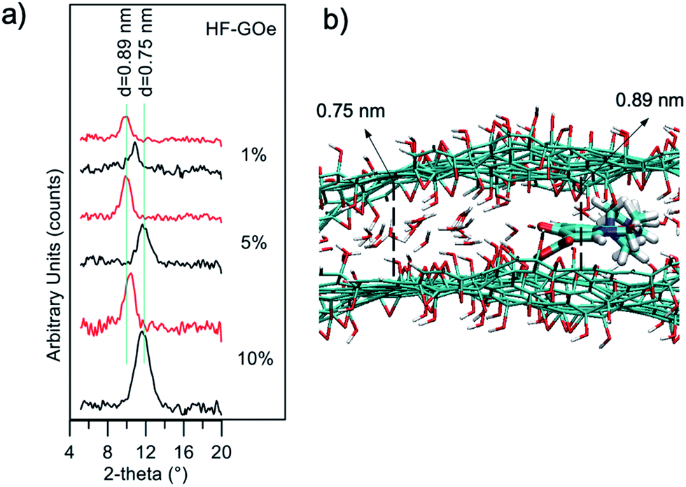 | ||
| Fig. 11 (a) XRD patterns of HF-GOe fibers before (black) and after (red) filtration of organic microcontaminants. Two vertical lines as references are at angles corresponding to 0.89 nm and 0.75 nm. (b) GO bilayers after ofloxacin intercalation. | ||
Atomistic molecular mechanics simulations may reveal insights into the adsorption and packing of molecules interacting with carbon nanomaterials.30 Thus, molecular modelling simulations of GO–ofloxacin interactions were performed for a deeper understanding of the removal mechanism. First, simulations show that the spacing of 0.75 nm observed for GO (Fig. 11, black curves) can be explained by considering the uptake of a water monolayer in the interlayer space of GO.31 Indeed, GO preserves the layered structure of graphite, but in contrast to graphite, it is hydrophilic, thus water molecules are hardly completely removed from GO layers. Consequently, spacings of carbon layers in the range from 0.6 to 1.2 nm are observed in GO, depending on the water content of the samples.32
This water layer is crucial to reach equilibrium spacing between the GO layers because an attractive force between the two negative GO sheets is needed to overcome the electrostatic repulsive force between the GO layers. Intercalation of ofloxacin between the GO layers (Fig. 11b) generates an increase in the spacing between the two GO layers from 0.75 to 0.89 nm. These values are in perfect agreement with observed XRD data (Fig. 11a, red profiles).
In fact, considering that (i) the size of a water molecule is ∼0.25 nm and the size of ofloxacin is ∼0.4 nm, (ii) during the intercalation process, the GO is locally dehydrated, an increase of ∼0.15 nm is expected upon intercalation, as observed experimentally by XRD measurements and by molecular modelling simulations.
Collectively, the multitarget filtration experiments show that the synergic action of the PES membrane and GO coating porosity (micrometric and nanometric pores, respectively) allows the removal from solution of large biological objects and small molecules at the same time. In contrast to simple mixtures or bi-layered GO–polymer composites previously described,22 the approach described here allows the nano-adsorbent component (i.e. the GO) to be positioned exactly on the surface more exposed to the solution, in particular in proximity to the nanopores. The results obtained show that this geometry allows a significant removal of EOC to be obtained even with a short contact time and for low GO loadings, in particular when the GO is placed in the inner surface of the fibers, where contact time with the contaminated solution is maximal (see scheme in Fig. 12).
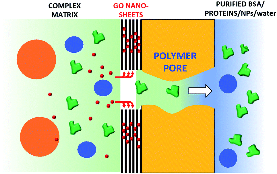 | ||
| Fig. 12 Simplified working mechanism of HF-GO, allowing simultaneous filtration of BSA through PES and GO-promoted adsorption of OFLOX, Ciproflox and RhB. The GO layer does not cover all the pores, thus allowing EOC molecules to intercalate and nanoobjects to pass through the core–shell HF. | ||
Conclusions
In conclusion, GO coating was achieved by a simple and mild procedure on already commercially available microfiltration PES hollow fiber modules. While unmodified filters could stop large objects and let BSA and small molecule EOCs pass through, only HF-GO hollow fiber filters were able to selectively capture three target EOCs of environmental relevance. Air permeation tests revealed that diffusing molecules are forced to travel around the GO sheets along tortuous paths, depending on the in-plane distance between two near GO sheets and the intrinsic aspect ratio of the 2-D materials. This is of course not useful for the filtration of large molecules like BSA, with a size of 20 nm, but could be useful for the selective filtration of smaller molecules such as EOCs. Accordingly, combined XRD analysis of virgin and used membranes and molecular modelling simulations revealed intercalation of organic molecules through the GO layers as the mechanism of adsorption. This work demonstrates that HF-GO modules can be useful for removing antibiotics from water and plasma matrices while letting proteins and nanoobjects pass though the HF pores, thus paving the way toward selective separation processes for biomedical and water treatment applications.Conflicts of interest
There are no conflicts to declare.Acknowledgements
The research leading to these results has received funding from the European Union’s Horizon 2020 Research and Innovation Programme under GrapheneCore2 785219 – Graphene Flagship, POR-FERS 2014–2020 DGR 986/2018 MEDFIL (B54I19000030005) and Italian-PRIN 2017 NANO-CARBO-CAT (B54I19002770001). M. M. thanks Dr F. Belosi (CNR-ISAC) for useful discussions.References
- (a) S. Schulze, D. Zahn, R. Montes, R. Rodil, J. B. Quintana, T. P. Knepper, T. Reemtsma and U. Berger, Water Res., 2019, 153, 80–90 CrossRef CAS; (b) Recast of the EU drinking water directive, https://ec.europa.eu/info/law/better-regulation/initiatives/com-2017-753_en; (c) F. Mao, Y. He and K. Yew-Hoong Gin, Environ. Sci.: Water Res. Technol., 2019, 5, 209–223 RSC.
- (a) K. Zahri, K. C. Wong, P. S. Goh and A. F. Ismail, RSC Adv., 2016, 6, 89130–89139 RSC; (b) F. David, F. Sanders, P. Zachary, P. Smith, R. Guo, M. Lloyd, C. Robeson, E. J. McGrath, D. R. Paul and B. D. Freeman, Polymer, 2013, 54, 4729–4761 CrossRef.
- D. Sholl and R. P. Lively, Nature, 2016, 532, 435–437 CrossRef.
- D. Li, R. Wang and T.-S. Chung, Sep. Purif. Technol., 2004, 40, 15–30 CrossRef CAS.
- (a) P. Westerhoff, P. Alvarez, Q. Li, J. Gardea-Torresdeyc and J. Zimmermand, Environ. Sci.: Nano, 2016, 3, 1241–1253 RSC; (b) C. Santhosh, V. Velmurugan, G. Jacob, S. K. Jeong, A. N. Grace and A. Bhatnagar, Chem. Eng. J., 2016, 306, 1116–1137 CrossRef CAS; (c) X. Zhu, K. Yangab and B. Chen, Environ. Sci.: Nano, 2017, 4, 2267–2285 RSC; (d) D. Miller, D. R. Dreyer, C. W. Bielawski, D. R. Paul and B. D. Freeman, Angew. Chem., Int. Ed., 2017, 56(17), 4662–4711 CrossRef CAS.
- J. Alam, A. K. Shukla, M. Alhoshan, L. Arockiasamy Dass, M. R. Muthumareeswaran, A. Khan and F. A. A. Ali, Adv. Polym. Technol., 2018, 37, 2597–2608 CrossRef CAS.
- R. Rezaee, S. Nasseri, A. Hossein Mahvi, R. Nabizadeh, S. A. Mousavi, A. Rashidi, A. Jafari and S. Nazmara, J. Environ. Health Sci. Eng., 2015, 13, 61 CrossRef.
- J. A. Prince, S. Bhuvana, V. Anbharasi, N. Ayyanar, K. V. K. Boodhoo and G. Singh, Water Res., 2016, 103, 311–318 CrossRef CAS.
- X. Zhu, K. Yangab and B. Chen, Environ. Sci.: Nano, 2017, 4, 2267–2285 RSC.
- M. Miculescu, V. Kumar Thakur, F. Miculescu and S. I. Voicu, Polym. Adv. Technol., 2016, 27, 844–859 CrossRef CAS.
- X. Wang, Y. Zhao, E. Tian, J. Li and Y. Ren, Adv. Mater. Interfaces, 2018, 5, 1701427 CrossRef.
- R. R. Nair, H. A. Wu, P. N. Jayaram, I. V. Grigorieva and A. K. Geim, Science, 2012, 335, 442 CrossRef CAS.
- N. Yousefi, X. Lu, M. Elimelech and N. Tufenkji, Nat. Nanotechnol., 2019, 14, 107–119 CrossRef CAS.
- F. Perreault, A. Fonseca de Faria and M. Elimelech, Chem. Soc. Rev., 2015, 44, 5861–5896 RSC.
- T. A. Tabish, F. A. Memon, D. E. Gomez, D. W. Horsell and S. Zhang, Sci. Rep., 2018, 8, 1817, DOI:10.1038/s41598-018-19978-8.
- L. Jiang, Y. Liu, S. Liu, G. Zeng, X. Hu, X. Hu, Z. Guo, X. Tan, L. Wang and Z. Wu, Environ. Sci. Technol., 2017, 51, 6352–6359 CrossRef CAS.
- G. Ersan, O. G. Apul, F. Perreault and T. Karanfil, Water Res., 2017, 126, 385–398 CrossRef CAS.
- (a) D. Pakulski, W. Czepa, S. Witomska, A. Aliprandi, P. P. V. Patroniak, A. Ciesielski and P. Samori’, J. Mater. Chem. A, 2018, 6, 9384–9390 RSC; (b) W. Gao, M. Majumder, L. B. Alemany, T. N. Narayanan, M. A. Ibarra, B. K. Pradhan and P. M. Ajayan, ACS Appl. Mater. Interfaces, 2011, 3, 1821–1826 CrossRef CAS; (c) M. Durso, A. I. Borrachero-Conejo, C. Bettini, E. Treossi, A. Scidà, E. Saracino, M. Gazzano, M. Christian, V. Morandi, G. Tuci, G. Giambastiani, L. de Ottaviano, F. Perrozzi, V. Benfenati, M. Melucci and V. Palermo, J. Mater. Chem. B, 2018, 6, 5335–5342 RSC.
- C. J. Madadrang, H. Y. Kim, G. Gao, N. Wang, J. Zhu, H. Feng, M. Gorring, M. L. Kasner and S. Hou, ACS Appl. Mater. Interfaces, 2012, 4, 1186–1193 CrossRef CAS.
- M.-P. Wei, H. Chai, Y.-L. Cao and D.-Z. Jia, J. Colloid Interface Sci., 2018, 524, 297–305 CrossRef CAS.
- C.-Z. Zhang, Y. Yuan and Z. Guo, Sep. Sci. Technol., 2018, 53, 1666–1677 CrossRef CAS.
- M. Zambianchi, M. Durso, A. Liscio, E. Treossi, C. Bettini, M. L. Capobianco, A. Aluigi, A. Kovtun, G. Ruani, F. Corticelli, M. Brucale, V. Palermo, M. L. Navacchia and M. Melucci, Chem. Eng. J., 2017, 326, 130–140 CrossRef CAS.
- M. Zambianchi, A. Aluigi, M. L. Capobianco, F. Corticelli, I. Elmi, S. Zampolli, F. Stante, L. Bocchi, F. Belosi, M. L. Navacchia and M. Melucci, Adv. Sustainable Syst., 2017, 1, 1700019 CrossRef.
- A. Kovtun, M. Zambianchi, C. Bettini, A. Liscio, M. Gazzano, F. Corticelli, E. Treossi, M. L. Navacchia, V. Palermo and M. Melucci, Nanoscale, 2019, 11, 22780, 10.1039/c9nr06897j.
- A. Liscio, K. Kouroupis-Agalou, A. Kovtun, E. Gebremedhn, M. El Garah, W. Rekab, E. Orgiu, L. Giorgini, P. Samori’, D. Beljonne and V. Palermo, ChemPlusChem, 2017, 82, 358–367 CrossRef CAS.
- J. I. Langford and A. J. C. Wilson Scherrer, J. Appl. Crystallogr., 1978, 11, 102–113 CrossRef CAS.
- J. Abraham, K. S. Vasu, C. D. Williams, K. Gopinadhan, Y. Su, C. T. Cherian, J. Dix, E. Prestat, S. J. Haigh, I. V. Grigorieva, P. Carbone, A. K. Geim and R. R. Nair, Nat. Nanotechnol., 2017, 12, 546–550 CrossRef CAS.
- (a) A. Molla, Y. Li, B. Mandal, S. G. Kang, S. H. Hur and J. S. Chung, Appl. Surf. Sci., 2019, 464, 170–177 CrossRef CASP. Bradder, S. King, L. S. Wang and S. Liu, J. Chem. Eng., 2011, 56, 138–141 CAS; (b) Q. Konga, X. Hea, L. Shuc and M.-S. Miao, Process Saf. Environ. Prot., 2017, 112, 254–264 CrossRef.
- R. Mailler, J. Gasperi, Y. Coquet, S. Deshayes, S. Zedek, C. Cren-Oliv, N. Cartiser, V. Eudes, A. Bressy, E. Caupos, R. Moilleron, G. Chebbo and V. Rocher, Water Res., 2015, 72, 315–330 CrossRef CAS.
- M. Calvaresi and F. Zerbetto, J. Mater. Chem. A, 2014, 2, 12123–12135 RSC.
- S. Zheng, Q. Tu, J. J. Urban, S. Li and B. Mi, ACS Nano, 2017, 11, 6440–6450 CrossRef CAS.
- (a) A. Buchsteiner, A. Lerf and J. Pieper, J. Phys. Chem. B, 2006, 110(45), 22328–22338 CrossRef CAS; (b) A. V. Talyzin, T. Hausmaninger, S. Youa and T. Szabo, Nanoscale, 2014, 6, 272–281 RSC.
Footnotes |
| † Electronic supplementary information (ESI) available. See DOI: 10.1039/c9fd00117d |
| ‡ These authors contributed equally to this work. |
| This journal is © The Royal Society of Chemistry 2021 |