 Open Access Article
 This Open Access Article is licensed under a Creative Commons Attribution-Non Commercial 3.0 Unported Licence
Multifunctional coatings of exfoliated and reassembled graphite on cellulosic substrates†
Leandra Pereira
Santos
 *ad,
Douglas
Soares da Silva
a,
João Paulo
Ferreira Bertacchi
a,
Kelly Schneider
Moreira
b,
Thiago Augusto
Lima Burgo
b,
Bruno Carreira
Batista
c,
Jeferson dos
Santos
a,
Patrick
Alvarenga de Paula
a and
Fernando
Galembeck
*ad
*ad,
Douglas
Soares da Silva
a,
João Paulo
Ferreira Bertacchi
a,
Kelly Schneider
Moreira
b,
Thiago Augusto
Lima Burgo
b,
Bruno Carreira
Batista
c,
Jeferson dos
Santos
a,
Patrick
Alvarenga de Paula
a and
Fernando
Galembeck
*ad
aInstitute of Chemistry, University of Campinas, Campinas, 13083-970, SP, Brazil. E-mail: fernagal@unicamp.br; leandrapereiradossantos@gmail.com
bPhysics and Chemistry Department, Univ. Fed. Santa Maria, Santa Maria, RS, Brazil
cInstitute of Chemistry, Univ. Fed. do Mato Grosso do Sul, Campo Grande, MS, Brazil
dGG & FG Consulting & Development, Campinas, 13084-723, SP, Brazil
First published on 28th February 2020
Abstract
Exfoliated and reassembled graphite (ERG) forms macroscopic, high aspect ratio (1![[thin space (1/6-em)]](https://www.rsc.org/images/entities/char_2009.gif) :>106) and highly conductive coating layers that are strongly adherent to paper, wood, cloth, ceramic and other substrates. The coating precursor is an aqueous dispersion of graphite that exfoliates spontaneously in alkaline cellulose solutions, forming stable dispersions. These can be applied to the substrates by using different painting, coating and lithography techniques. The coating morphology changes from highly smooth to porous and rough, depending on the finishing procedure used. Coated paper sheets are flexible and they perform as leads in electrical circuitry and as electrodes in electrodeposition, supercapacitors, hygroelectricity cells and other electrochemical devices suitable for flexible and wearable electronics. These unique properties of ERG are explained as a consequence of the amphiphilic character of cellulose, which allows it to play the roles of exfoliant, dispersant, stabilizer, adhesive and plasticizer, while graphite powder is transformed into a cohesive laminated nanocomposite.
:>106) and highly conductive coating layers that are strongly adherent to paper, wood, cloth, ceramic and other substrates. The coating precursor is an aqueous dispersion of graphite that exfoliates spontaneously in alkaline cellulose solutions, forming stable dispersions. These can be applied to the substrates by using different painting, coating and lithography techniques. The coating morphology changes from highly smooth to porous and rough, depending on the finishing procedure used. Coated paper sheets are flexible and they perform as leads in electrical circuitry and as electrodes in electrodeposition, supercapacitors, hygroelectricity cells and other electrochemical devices suitable for flexible and wearable electronics. These unique properties of ERG are explained as a consequence of the amphiphilic character of cellulose, which allows it to play the roles of exfoliant, dispersant, stabilizer, adhesive and plasticizer, while graphite powder is transformed into a cohesive laminated nanocomposite.
Introduction
The outstanding properties of graphene and related 2D materials (GRM) have been attracting great attention and they are being explored to create nanomaterials that perform multiple functions in various applications.1–13 Composites are the most common industrial graphene-based products, but the quality of commercially available graphene is usually low compared to the materials obtained in the laboratory.Graphene is often commercially supplied as a powder and it is not expected that <1 nm thin, electroneutral sheets will remain well separated when they touch each other, due to the omnipresent van der Waals forces.
Thus, single-layer graphene cannot exist as a dry powder under normal terrestrial conditions. This is one of the factors preventing widespread use of graphene in the many industrial applications where it could be the basis for much radical innovation.
Spontaneous graphene aggregation is accompanied by significant changes in its physical properties. For instance, the electrical conductivity of graphene is among the highest known, surpassing copper and matching silver. However, piling up graphene sheets lowers its conductivity steeply: the electrical conductivity of a 100-layer lamella is in the same range as that of graphite. On the other hand, the resistance of a single graphene layer is 33 ohms per square, too high for any applications requiring high currents. Based on data for single-wall carbon nanotubes,14 graphene’s ability to sustain a high current may be as high as the 1012 A m−2 range, thus a 1 metre wide sheet could hold a 50 A current. Different approaches are thus being taken to explore graphene in high-ampacity15 materials for power transmission, as well as in thermal16 or strengthening17,18 applications through the formation of graphene composites, e.g. the superhelix graphene/copper nanocomposite wires19 with 600 μm overall diameter which can carry 5.8 × 10¹⁰ A m−2.
Moulding powders facilitates particle aggregation, so that we cannot think of moulded graphene macroscopic monoliths. Graphite itself can be shaped in macroscopic bars, cylinders and plates, allowing its use in power applications, but this is in turn limited by the brittleness of graphite monoliths.
In this laboratory, we approached this problem by exfoliating graphite in aqueous alkaline cellulose solutions, thus producing dispersions suitable for making conductive coatings or monoliths.20 Graphite exfoliation has been described in the literature by using various dispersing agents and by oxidizing to graphene oxide. Direct exfoliation in water is achieved using dispersant solvents, surfactants and polymers, high pressure,21 extended sonication22 and mechanochemical action (e.g. in the presence of melamine),23 followed by freeze-drying. This introduces new problems due to the negative effect of exfoliant residues which are often electrical insulators. Graphite exfoliation by cellulose takes place at dispersant/graphite weight ratios lower than 1:60; the dispersant cellulose becomes an excellent adhesive when the medium pH is lowered.24 Wet cellulose is a low-Tg polymer that acts as a plasticizer of the exfoliated lamellae. Most importantly, the thin exfoliated lamellae reassemble on the substrates, forming extended, continuous and insoluble films. This combination of properties is not matched by any other dispersant, notwithstanding all the efforts reported in the literature.
Graphite exfoliation and reassembly can then produce macroscopic micron-thick layers of a new material, extending over many square meters and perhaps much greater areas. The aspect ratio (width/thickness) of this material is 106 or higher, well above the aspect ratio of a single graphene sheet with 10 microns width, and thus it performs as a macroscopic 2D material. This paper describes different applications of exfoliated and reassembled graphite (ERG) that may contribute to increasing the strategic and economic impact of 2D materials.
Results and discussion
Graphite exfoliated in aqueous cellulosic solutions forms non-Newtonian fluids, appearing as liquid dispersions, pastes or self-standing gels. When sheared, they show rheo-optical effects, as expected for reflective particles with large aspect ratios. The dispersions may be stored and used for many months without significant change in their performance except for an increase in viscosity due to spontaneous further exfoliation. They wet and spread on various types of lignocellulosic or ceramic surfaces: wood, paper, cardboard, cloth, charcoal, brick, china and a ceramic fibre mat. Detailed information on the dispersion properties is beyond the scope of this paper but will be published in the near future.Substrate coating and finishing
Different coating techniques, like spraying, spreading, painting with roll or brush, bathing, silk-screening and lithography, have already been used to produce uniform and adhesive coatings with thickness ranging from some nanometres to higher than a hundred microns, on smooth or rough surfaces that may have complex shapes. Some examples are pictured in the ESI (Fig. S1†).Successive coating layers may be applied to the substrate, allowing water to evaporate in between successive applications. Thus, it is possible to repair damaged coatings or to use additive manufacture techniques with these materials.
Upon drying, the exfoliated graphite lamellae reassemble, forming a continuous adherent film, irrespective of the substrate roughness. Drying under air is concurrent with CO2 uptake which lowers the pH and renders cellulose insoluble. The amphiphilic character of cellulose allows its adhesion to different lignocellulosic and ceramic materials. Cellulose is thus a good binding agent for making compatible multiphasic solid coatings.
The ERG surface is a rough network of cellulose fibrils spread over flat areas, as shown in the optical micrograph in Fig. 1. The intensity ratios of Raman spectra acquired from different spots show the presence of graphite and other kinds of graphene assemblies,25 while the intensity of the cellulose fluorescence band is highly variable.
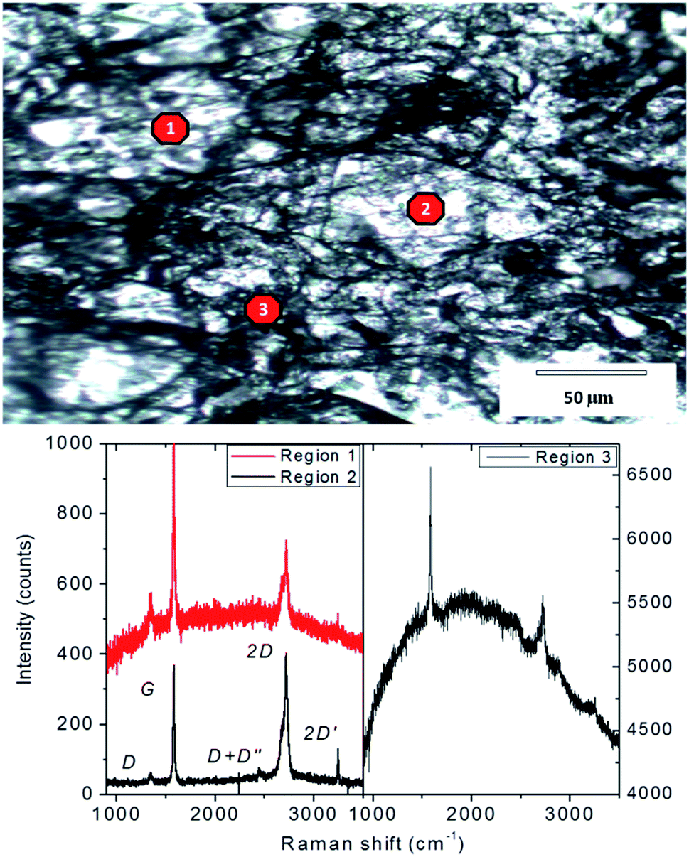 | ||
| Fig. 1 Top: Optical micrograph of ERG-coated paper surface. Bottom: Raman spectra obtained from 3 different points. The Raman laser spot diameter is ca. 1 micron. | ||
The ERG coatings may be finished by various techniques to produce smooth surfaces, as shown in Fig. 2.
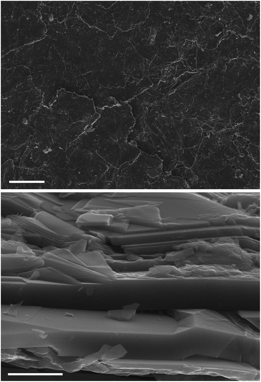 | ||
| Fig. 2 Top: SEM micrograph of an ERG layer painted on paper. Bottom: View of a cut side surface. Scale bars: top, 100 μm; bottom, 2 μm. | ||
The SEM micrograph of the finished ERG surface shows a flat layer of irregular particles that are predominantly aligned along the surface plane. Cellulose is also seen in the coating side view as a material with irregular shape, lying on the lamellae flat surfaces and also in between them. Cellulose occupies only a fraction of the conductive graphitic particle surfaces, allowing for electrical contact across the whole coating layer.
AFM micrographs in various modes (topography, friction force and conductive probe) are shown in Fig. 3, and they provide valuable information on ERG assembly. The topography measurements show plates with thickness of a few tens of nanometers as well as steps that are a few nm thick.
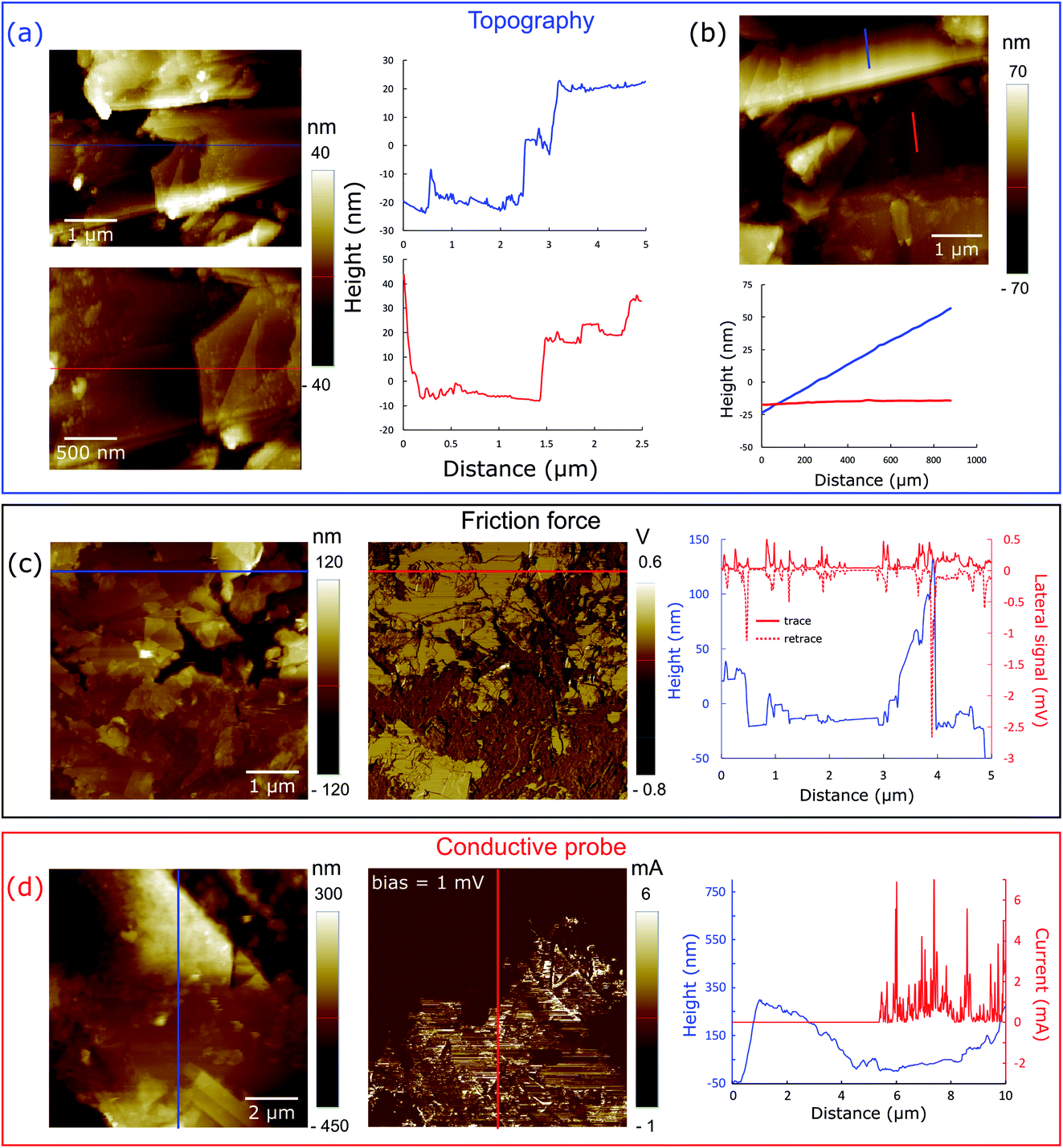 | ||
| Fig. 3 Scanning probe microscopy images of a calendered ERG coating on paper. (a) and (b) Topography images and line-scans showing the morphological aspects of the nanocomposite. (c) Friction force microscopy showing height and lateral force plots along the line-scans drawn over the micrographs. (d) Conductive probe AFM: topography (left) and current (right) mode images of the calendered surface of ERG-coated paper. Height and current plots along the vertical lines drawn in the images show that the graphite domains exhibit a high electric current response. | ||
The friction force micrographs show that the surface has extensive low friction domains, interspersed with higher friction areas, while the conductive probe images verify the coexistence of conductive and non-conductive domains.
The coatings are thus anisotropic macroscopic sheets made by joining anisotropic particles aligned along the surface plane. Different from common graphite materials, ERG layers are flexible, and they can be made stiffer or softer by reversibly plasticizing the interspersed cellulose with water vapor or liquid.
Coated substrates can be bent to low curvature radii, and mechanical damage due to bending is easily repaired by retouching, or by self-repair triggered by wetting and pressing of the defective area. Coating plasticity is assigned to the unprecedented ERG microstructure shown in the micrographs, in which wide bare lamellar surfaces are held together by strong cellulose fibrils and adhesive layers that occupy only a fraction of their surface area, leaving most conductive surfaces free to contact their neighbours.
Electrical resistance at the macro and nanoscales
The low surface resistance of ERG-coated paper has already been described in previous work, but significant improvement has been achieved since the original publication. Exploring various graphite and cellulose raw materials over a broad range of compositions and using various finishing procedures provided a number of formulations suitable for specific purposes. As expected, dispersions with higher graphite/cellulose weight ratios produced coatings with lower surface resistance.Fig. 4 shows resistance measurements taken along a 1 cm wide strip of an ERG-coated paper sheet, both as a recently prepared dry film and after calendering. The coating thicknesses were respectively 124 and 83 μm. From the slopes and intercepts of these plots, we obtain 22.4 and 1.1 ohms per square for the surface resistance and 10.9 and 2.1 ohms for the contact resistance of the unfinished and finished paper, respectively. Combined with the coating thicknesses, this yields 2.8 × 10⁻³ and 9.1 × 10⁻⁵ ohms per m for the resistivity, respectively.
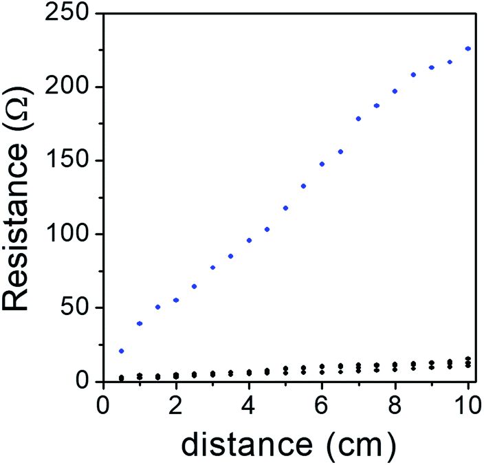 | ||
| Fig. 4 Electrical resistance of 1 cm wide as-prepared (blue dots) ERG-coated paper sheets and calendered (black dots) ERG-coated paper sheets, as a function of distance between the measuring probe tips. | ||
These figures may be too high or low for some desired applications, but they are easily changed by changing the composition of the dispersion used, the sample thickness, the finishing procedure and the contact with the metal probes. This can be better understood by looking at the SEM images (Fig. 2) and especially the scanning probe micrographs (Fig. 3d), in which electrical current passes predominantly through the graphite sheets, but decreases abruptly in the cellulose-rich regions.
So far, the lowest surface resistance achieved in this laboratory is 0.6 ohms per square for another film of ERG-coated, washed and calendered Kraft paper, followed by 0.7 ohms per square for a 40 × 40 cm ERG-coated medium density fiberboard (MDF).
Further resistance lowering is probably still possible, by improving the juxtaposition of the lamellae and by reducing the amount of cellulose in the finished coating.
Coating adhesion
ERG coatings do not peel off from flexed coated paper, cardboard and cloth. Sharp bends may fracture thicker coatings, but these also resist peeling, even adjacent to the fracture line. ERG coating adhesion was tested following the ASTM D 3359-97 Standard, and the results pictured in Fig. 5 show that no square in the testing grid was withdrawn, and neither were the grid square tips damaged, as shown in Fig. 5, top row. The left side shows a picture of the grid before the adhesion test, and the picture in the center shows the grid after the adhesive tape was peeled off and does not show visible damage. The light discoloration of the tape used in this test is due to a small amount of delaminated graphene lamellae, evidencing that adhesion between the piled-up graphene layers is much lower than ERG adhesion to the substrate. The amount of peeled off ERG was quantified as shown in the center row in Fig. 5, showing that ten successive peeling tests removed only a small amount of the surface coating material. This is visualized in the bottom row, confirming that the successive peeling steps removed approximately the same amounts of graphene/nanographite, as shown in the weight loss plot. Together, these results show that ERG coatings may be used to prevent unwanted adhesion on the coated surfaces, since the adherent bodies can be easily peeled off, as the adhesive tapes were in this experiment.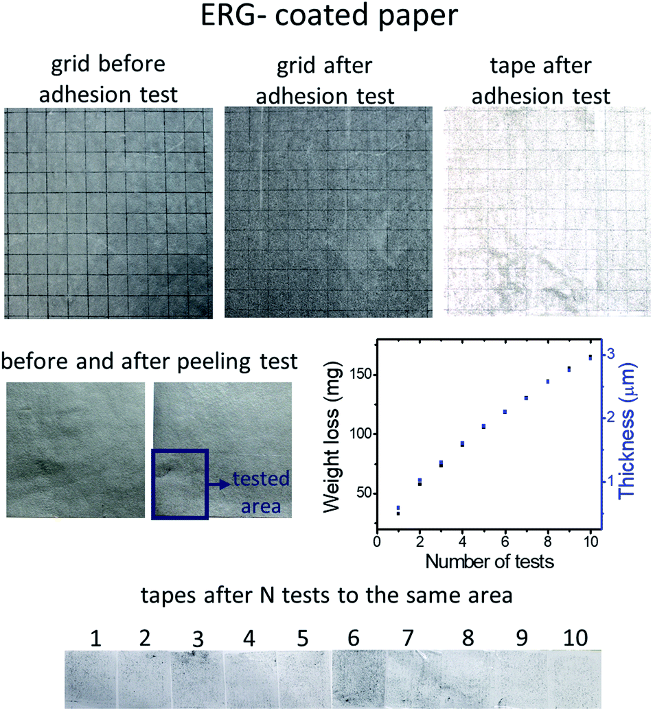 | ||
| Fig. 5 Top row: Picture of a piece of ERG-coated paper that was tested for coating adhesion (left), the ERG-coated paper after the adhesion test (center), and the adhesive tape used in the test (right). Center row: A sheet of another sample, where the lower left corner layers within the lamellae, together with a small amount of adhesive cellulose that persists within the coating, were successfully coated with adhesive tape and peeled off ten times (left, center), and a plot of sample weight loss and the corresponding decrease in thickness, calculated using the weight data (right). Bottom: Pictures of the ten tapes used. | ||
Thus, regenerated graphite coatings display an unusual combination of adhesive properties: they are strongly adherent to the substrate, but not to external adherent bodies.
This is expected, considering the poor adhesion among graphene layers.
Wetting and swelling
The wetting behavior of the graphite coatings depends largely on their specific composition and finish, as shown by the contact angle measurements presented in Fig. 6. As-prepared dry ERG-coated paper is wetted by water and the testing droplet is slowly drawn to the underlying paper sheet. This is drastically changed by calendering, which increases the initial water–ERG contact angle, keeping it nearly steady during droplet evaporation. Coating with polydimethylsiloxane increases the contact angle, which levels off at just below 90°.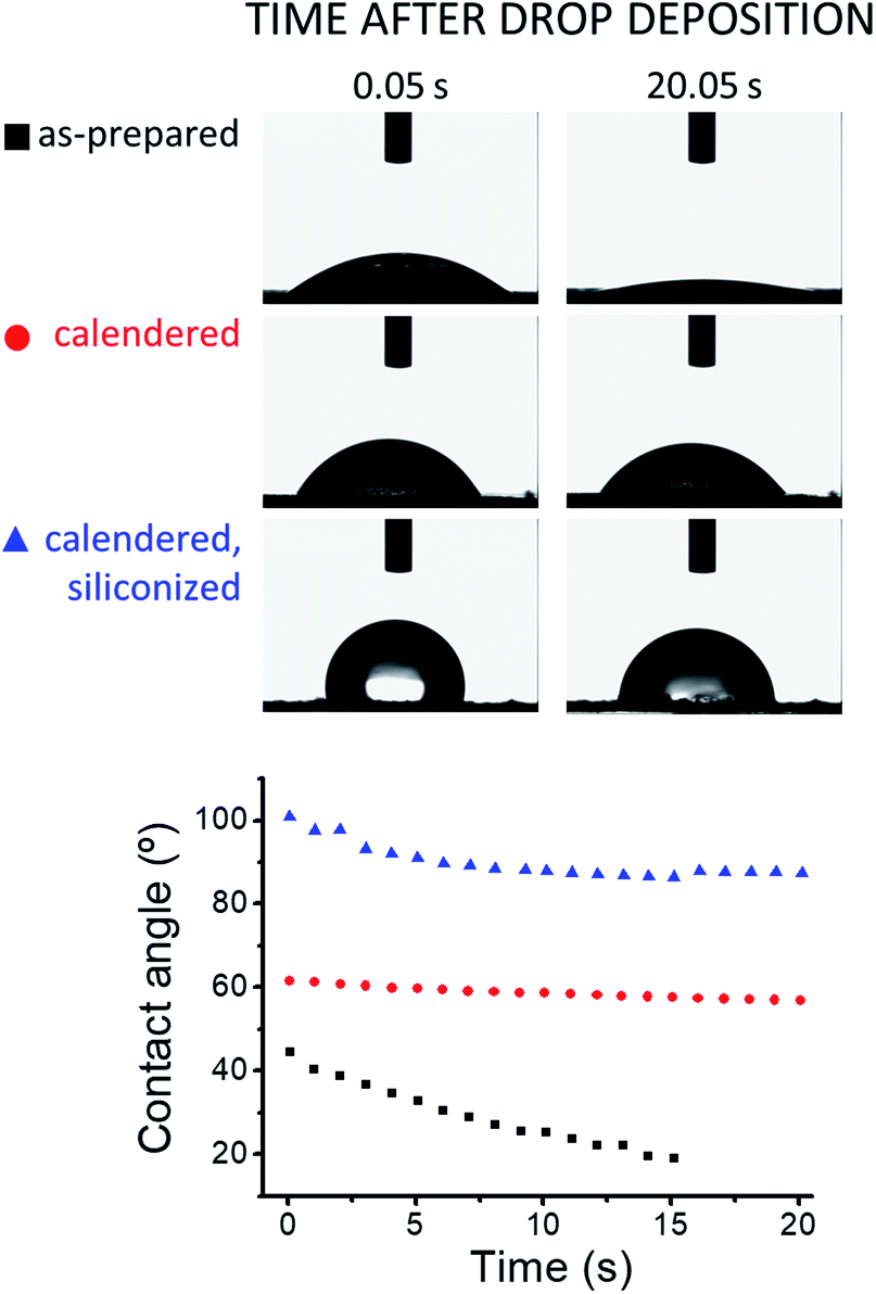 | ||
| Fig. 6 Advancing contact angle measurements of 5 μL sessile water drops resting on samples of paper coated with ERG. | ||
The remarkable effect of calendering on water contact angle is expected, considering the decrease in surface roughness accompanying the realignment of the surface lamellae under pressure. This also explains the negligible change in contact angle during droplet evaporation, considering that advancing and receding contact angles are expected to be identical on smooth, chemically uniform surfaces.
Conductive leads in electric circuits
Conductive inks26 are often designed to make printed and flexible circuitry. ERG coatings can be used in this way, and ERG paper is easily cut, coated and assembled as the leads in circuit boards. This has been demonstrated by building kits for students experimenting on electricity and electrochemistry.Fig. 7 shows a simple circuit for distinguishing conductive from non-conductive materials, assembled from a kit that includes parts used in eleven electrochemical experiments.
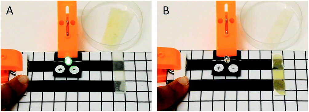 | ||
| Fig. 7 Pictures of a circuit board assembled from a kit made for student experiments on electricity and electrochemistry. A piece of filter paper wetted with (A) an aqueous solution of NaCl (0.1 mol L−1) and (B) cooking oil is placed between the conductive leads. A LED indicates the onset of electric current and it is lit on the left only. | ||
Electrodes
ERG-coated paper, wood, brick and other materials are robust electrodes for various applications. For instance, copper electrodeposition is easily done, producing copper films on the coated paper sheets, as shown in Fig. 8. Surface coverage by deposited copper follows the expected linear relationship with t1/2.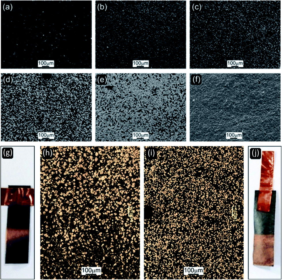 | ||
| Fig. 8 Upper: SEM micrographs of copper electrodeposited on an ERG-coated calendered surface, using a 0.5 mol L−1 solution at 2.85 mA cm−2. (a) is the initial sample and (b)–(f) are samples withdrawn from the copper solution after 5, 10, 30, 60 and 120 minutes, respectively. Lower: Two ERG-coated paper strips (g and j) used for copper electrodeposition are shown together with optical micrographs (h and i) of the copper coated areas. The sample on the right was calendered, the other was not. | ||
Energy applications
Graphite and graphene perform multiple roles in electrochemical systems, especially supercapacitors27,28 and cells or batteries.| Components | Capacitance (mF cm−2) |
|---|---|
| Ni3V2O8@PANI30 | 585 |
| Annealed carbon cloth31 | 2900 |
| Ni(OH)2/C/Cu//Mn3O4/C/Cu32 | 216 |
| ERG on paper (this work) | 350 |
| Activated carbon (AC) on polyimide film33 | 35 |
| Graphene/AC on polyimide film19 | 37 |
| Graphene on polyimide film19 | 8 |
| MnCo2O4 hollow spheres on carbon fibres34 | 800 |
| P3MT/HACNT on PDMS35 | 3100 |
| HACNT on PDMS21 | 750 |
| Buckypaper on PDMS21 | 250 |
| Graphene–graphite/PU36 | 16 |
This can be understood by considering the possibility of making thick ERG coatings, so that loading the electrode with electroactive material compensates for its low specific capacitance.
Using higher amounts of electrode materials is facilitated by their low cost, great availability and the possibility of designing and building capacitors as parts of manufactured goods, housing and equipment. This can be done without any safety concerns, since EDL capacitor voltages seldom exceed 2.5 volts.
Desired combinations of electrode properties are achieved by adding other components to ERG and using suitable processes and finishing techniques to tailor the electrodes to different applications. It is thus possible to combine the conductive properties of ERG not only with activated charcoal but also with many other components, to achieve the capacitance or pseudo capacitance shown e.g. by nickel vanadate@PANI, MnCo2O4 hollow spheres, poly(3-methylthiophene)/horizontally aligned carbon nanotubes (P3MT/HACNT) on PDMS, or iron hydroxide nanoparticles which were recently disclosed as a new benchmark.
Hygroelectricity37–47 is a recent development for energy scavenging, based on water ion partition during adsorption–desorption in a moist atmosphere or pure water. It has been implemented in different ways, and a simple experimental setup is an asymmetric capacitor under humid air or wetted by pure water. It can be observed by assembling capacitors using two paper electrodes coated with different graphite dispersions, or a capacitor built using a conductive paper electrode and an aluminium sheet.
The power output of a series arrangement is sufficient for energizing low-power applications, fully independent of the grid and without consuming valuable metal electrodes from electrochemical cells and batteries. A simple setup that keeps many LEDs continuously lit for a few days is shown in Fig. 9.
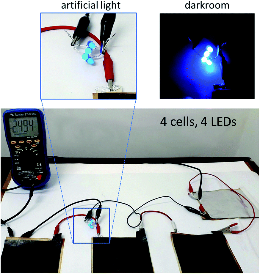 | ||
| Fig. 9 Electric circuit consisting of four hygroelectricity cells in series with four blue LEDs. The hygroelectricity cell is formed by an aluminum electrode and an ERG-coated paper electrode. A piece of water-soaked filter paper placed between the electrodes keeps the cell humid. The closed-circuit voltage is approximately 2.5 V. | ||
Friction, fire resistant surfaces and electrical heaters
Beyond its electrical properties, graphite is used as a lubricant and it is resistant to fire. For this reason, ERG coatings show useful anti-friction and fire resistance properties. Beyond that, its tunable electrical resistance makes it suitable to be used in low-power density heaters. Heating uses a significant part of the energy consumed globally and it is often done using heating elements operating at much higher temperature than the heated bodies, decreasing the heater efficiency.Benchmarking
The procedures used to obtain the oriented graphite coatings and the results achieved differ from current graphene and graphite-based inks or paints,7 opening many possibilities for the development of new products designed for different applications.A comparison of ERG with current conductive inks and coatings and some reference materials is shown in Table 2. Coating resistance is often expressed as the resistance measured by contacting the surface with the probe leads and it is expressed in ohms per square, R = ρ/h where ρ is the resistivity and h is the film thickness. For instance, organic photovoltaics require 10 Ω per square sheet resistance which is achieved using 1 μm-thick films of highly conductive metals, like Au, Cu and Ag. There has been great progress in lowering the sheet resistance of films applied to substrates, and an excellent result was published recently, using a procedure based on graphite exfoliation under high shear rate. This was done in the presence of Na-carboxymethylcellulose at concentrations as high as 100 g /L−1, and the authors achieved <2 Ω per square sheet resistance, which is already in the range required for printed RFID antennas.
| Material | Resistivity (Ω m−1) | Resistance (Ω per square) | Thickness (m) |
|---|---|---|---|
| Graphene monolayer | 10−8 | 33 | 3 × 10⁻¹⁰ (single sheet) |
| Multilayer graphene49 | 10−6 | 33 | 3 × 10⁻⁸ (100 sheets) |
| Graphene thin films exfoliated under high pressure21 | 2 × 10⁻⁵ | 3 to 50 × 10−6 | |
| Graphene thin films exfoliated under extended sonication22 | 2.3 × 10⁻³ | ||
| Graphite (basal) | 2 × 10⁻⁶ | 0.3 | 6 × 10⁻⁶ (20k sheets) |
| ERG (including substrate, best result in this lab) | 0.6 | ||
| Microfluidized graphite50 | 2.5 × 10⁻⁴ | 2 | |
| Commercial silver ink51 | 12.5 × 10⁻⁵ | 5 × 10⁻³ | 2.5 × 10⁻⁶ |
| SWNT dispersed in SDBS52 | 4 | ||
| MnO2-coated hollow carbon microspheres53 | 3 | ||
| CNTs coated active carbon54 | 20 | ||
| Silver nanowires55 | 8 | ||
| Encapsulated graphene/CuNT/EVA/PET hybrid films56 | 8 |
The resistance of ERG coatings varies within a broad range, depending on the composition of the dispersion used, thickness and finishing procedure. The lowest value achieved is 0.6 ohms per square, which is suitable for many macroscopic applications.
For instance, any square coating with this resistance dissipates only 1.3 W under a 15 A current. If the voltage fed to the circuit is 120 V, the power dissipated in the coating square is less than 0.1%.
In many applications, the conductive materials used should also comply with safety and environmental requirements, especially when the coated products are designed for a single use, e.g. in medical applications. Materials printed or coated with ERG do not pose any difficulties concerning final destination, since they can be composted or treated by various thermal processes (e.g. gasification, pyrolysis), leaving behind only carbon rich residues which are environmentally valuable. The graphite used in this work was of mineral origin, but useful conductive carbon particles are currently being produced from waste and they are showing promising results in conductive rubber.48 Each system has its pros and cons, considering the specifications set for specific applications. The procedures used in this laboratory to make conductive ink and paint are based on a mild, low-shearing procedure for partial exfoliation of graphite, forming high-aspect ratio nanographite sheets. Energetic procedures like sonication or milling are avoided, to prevent breaking of the graphite particles. High dispersant concentrations are also avoided, allowing for maximal contact among the individual graphene lamellae in the reassembled graphite.
ERG and even graphite are no match for the electrical conductivity of silver, but they have an advantage: they do not undergo significant oxidation under air. This is a problem for silver, in which a poorly conductive oxide is formed spontaneously under air, increasing the contact resistance among the silver particles and decreasing the shelf-life of silver-based conductive inks.
The multiple roles of cellulose: exfoliating agent, adhesive, plasticizer
The ability of aqueous cellulose solutions to wet and exfoliate graphite, while keeping the thin lamellae stably dispersed in an aqueous medium, is explained by the amphiphilic character of the individual cellulose chains.ERG is made directly from the aqueous dispersion, avoiding the drying and powder handling steps which are required to make many current graphene products and compromise the quality of industrial products.57
Other properties of the extended thin ERG films described in the present work also derive from the properties of cellulose. ERG is resistant to water but it may swell, depending on the cellulose content. The moist films are plastic but they become rigid when dry. This is explained by the plasticizing role of cellulose chains interspersed with nanographite and graphene lamellae. The outcome is lamellae mobility, which allows their alignment along the film surface, exposing the basal plane to external electrical contacts. Low amounts of cellulose are required for coating cohesion and adhesion, as seen in the micrographs.
Moreover, cellulose chains are flat and they are likely adsorbed (within the dispersion) with a predominantly train conformation that leaves the flat graphitic surfaces largely unoccupied and suitable for electronic conduction.
The uniqueness of the contribution made by cellulose to ERG appears more clearly when we compare its performance to other widely used dispersants, for instance carboxymethylcellulose (CMC), a closely related modified cellulose. Graphite disperses well in aqueous solutions of CMC and the resulting dispersions can be used to paint paper, producing uniform coatings with low electrical resistance. However, the thin coating layers do not adhere strongly to flexible substrates: they do not withstand mechanical finishing procedures and they peel off the flexed substrates. This is a serious limitation in wearable circuitry. Moreover, CMC-based graphite coatings are easily re-dispersed in water and do not resist exposure to high humidity.
Exfoliating graphite and using it directly in its dispersions follows examples from the chemical industry, where highly unstable, sensitive or dangerous compounds, like phosgene, carbon disulphide, and sulphur trioxide as well as nickel and iron carbonyls seldom leave the plants to go anywhere. Using these chemicals in situ avoids huge handling, safety and environmental problems. In the present case, this approach combines top-down graphite exfoliation with its bottom-up reassembly as macroscopic continuous layers whose mechanical and handling properties differ pronouncedly from those of graphite powders or monoliths. The same approach can probably be used with other 2D materials to facilitate their use in various applications.
This is also in line with the work of many groups who have already opted for making graphene in situ, e.g. on copper foils.58
Experimental
Reagents
Different graphite types prepared by various procedures and with various particle dimensions were used in this laboratory, but the original results described in the present paper were obtained using graphite Grafine® 95100 (Nacional de Grafite, São Paulo-SP, 96.4% C, 3.5% ash, mesh size ≥ 325). Cellulose was used as the microcrystalline product Microcel®-101 (Blanver, São Paulo-SP, 50 μm average particle size, 0.26–0.31 g cm−3 density), and the solution of 50% NaOH in water was acquired from Synth (Diadema-SP).Sample preparation and handling procedures
Equipment and measurement procedures
Conclusions
Graphite dispersed in aqueous cellulose solutions is a bountiful source of new high-performance functional materials with various applications. This is largely due to the properties of cellulose which enable it to exfoliate graphite in aqueous solutions but also to perform as a plasticizing adhesive that allows the thin exfoliated lamellae to reassemble when they are applied on many different surfaces, forming extensive coating layers. Microscopy shows interesting features of the coatings which indicate the structural basis of their various macroscopic properties and applications. Coated paper and cloth can be bent to <1 cm curvature radii and the eventual damage is easily repaired.Changing the coating composition and surface finishing procedure produces a broad range of electrical properties, with surface resistance as low as 0.6 ohm per square, close to the limit obtained for thick graphite layers and well below the value for single graphene layers. This is adequate for many applications of conductive materials in everyday use, in circuits integrated on clothes and in components of instruments and IT devices, machinery, and car and housing parts. Other applications involve the making of electrodes for electrochemical cells, supercapacitors, energy scavenging based on hygroelectricity, and electrodeposition on paper, wood and ceramic substrates.
The fabrication processes offer many advantages: the raw materials are widely available commodities, and the coating fabrication and application are done using common procedures in the coating and paint industry. The only environmental risk in the making of these materials is the use of sodium hydroxide, which is commonly used in industry, e.g. to clean equipment. This chemical is neutralized by atmospheric CO2.
The exfoliated and reassembled graphite (ERG) shows other interesting features derived from the well-known properties of graphite: resistance to fire propagation, low friction, and high absorbance and emittance of light.
The singularities of ERG coatings derive from a number of unique properties of cellulose that are associated with its amphiphilic character: it is not soluble in common liquids, with very few exceptions. Dissolved cellulose adsorbs on many particulate solids, and the hydrophobic ring surface of its flat chain easily joins to graphene surfaces, producing spontaneous exfoliation of graphite under mild conditions. For these reasons, it is an excellent adhesive for exfoliated graphite thin lamellae, especially on cellulose surfaces.
Cellulose is plasticized by water and it can thus perform the role of a plasticizer within ERG. This endows the coatings with the ability to self-repair under high relative air humidity or when wet. For the same reason, successive coating layers show good mutual adhesion, and coating damage is quickly repaired by painting over it. This is further used in making circuit connections using graphite/cellulose as a conductive adhesive.
The approach used throughout this work circumvents some problems involved in making quality graphene (or even nanographite), and in storing, dispersing and applying it. Graphene is a high surface area non-polar substance that reaggregates easily, due to the well-known and irrevocable intermolecular van der Waals forces. Intensive efforts to produce high-quality graphene have been largely successful, and this is no longer the main difficulty responsible for its still low presence in multiple industrial applications where it is much needed.
Conflicts of interest
FG is one of the inventors listed in patent applications PCT/BR2016/050169, WO2017/063062A1, EP3363530 and US20180304210 and a partner in the GG & FG company which is currently funded by FAPESP (São Paulo State Research Foundation) to develop the materials and applications described in this paper.Acknowledgements
This work is supported by the Brazilian agencies MCTIC/CNPq (465452/2014-0), FAPESP (2014/50906-9) and Coordenação de Aperfeiçoamento de Pessoal de Nível Superior – Brazil (CAPES) – Finance Code 001 through INCT/INOMAT (National Institute for Complex Functional Materials). BCB thanks FAPESP (2016/02386-1), LPS thanks CAPES (88887.284776/2018-00) for a postdoctoral fellowship and FAPESP (2019/04565-9) for a research fellowship. Raman spectroscopy equipment was acquired by LMEOA (Institute of Physics of the University of Campinas) through grants EMU/FAPESP 2009/54066-7 and MCT/FINEP/CT-Infra 02/2010. The authors thank LNNano (CNPEM, Campinas) for technical assistance and access to selected equipment. The authors thank Ramon H. Z. dos Santos for preparing samples and technical assistance with X-ray tomography measurements. This work is currently also supported by FAPESP PIPE project 2018/00834-2.References
- C. N. R. Rao, A. K. Sood, K. S. Subrahmanyam and A. Govindaraj, Angew. Chem., Int. Ed., 2009, 48, 7752–7777 CrossRef CAS.
- A. C. Ferrari, F. Bonaccorso, V. Fal’ko, K. S. Novoselov, S. Roche, P. Bøggild, S. Borini, F. H. L. Koppens, V. Palermo, N. Pugno, J. A. Garrido, R. Sordan, A. Bianco, L. Ballerini, M. Prato, E. Lidorikis, J. Kivioja, C. Marinelli, T. Ryhänen, A. Morpurgo, J. N. Coleman, V. Nicolosi, L. Colombo, A. Fert, M. Garcia-Hernandez, A. Bachtold, G. F. Schneider, F. Guinea, C. Dekker, M. Barbone, Z. Sun, C. Galiotis, A. N. Grigorenko, G. Konstantatos, A. Kis, M. Katsnelson, L. Vandersypen, A. Loiseau, V. Morandi, D. Neumaier, E. Treossi, V. Pellegrini, M. Polini, A. Tredicucci, G. M. Williams, B. Hee Hong, J.-H. Ahn, J. Min Kim, H. Zirath, B. J. van Wees, H. van der Zant, L. Occhipinti, A. Di Matteo, I. A. Kinloch, T. Seyller, E. Quesnel, X. Feng, K. Teo, N. Rupesinghe, P. Hakonen, S. R. T. Neil, Q. Tannock, T. Löfwander and J. Kinaret, Nanoscale, 2015, 7, 4598–4810 RSC.
- Y. Zhu, H. Ji, H.-M. Cheng and R. S. Ruoff, Natl. Sci. Rev., 2018, 5, 90–101 CrossRef CAS.
- X. Li and L. Zhi, Chem. Soc. Rev., 2018, 47, 3189–3216 RSC.
- H. Sun, J. Zhu, D. Baumann, L. Peng, Y. Xu, I. Shakir, Y. Huang and X. Duan, Nat. Rev. Mater., 2019, 4, 45–60 CrossRef.
- A. Nag, A. Mitra and S. C. Mukhopadhyay, Sens. Actuators, A, 2018, 270, 177–194 CrossRef CAS.
- G. Hu, J. Kang, L. W. T. Ng, X. Zhu, R. C. T. Howe, C. G. Jones, M. C. Hersam and T. Hasan, Chem. Soc. Rev., 2018, 47, 3265–3300 RSC.
- D. Li, W.-Y. Lai, Y.-Z. Zhang and W. Huang, Adv. Mater., 2018, 30, 1704738 CrossRef.
- X. Shi, S. Pei, F. Zhou, W. Ren, H.-M. Cheng, Z.-S. Wu and X. Bao, Energy Environ. Sci., 2019, 12, 1534–1541 RSC.
- X. Xu and Y.-L. Hsieh, Nanoscale, 2019, 11, 11719–11729 RSC.
- K. R. Paton, E. Varrla, C. Backes, R. J. Smith, U. Khan, A. O’Neill, C. Boland, M. Lotya, O. M. Istrate, P. King, T. Higgins, S. Barwich, P. May, P. Puczkarski, I. Ahmed, M. Moebius, H. Pettersson, E. Long, J. Coelho, S. E. O’Brien, E. K. McGuire, B. M. Sanchez, G. S. Duesberg, N. McEvoy, T. J. Pennycook, C. Downing, A. Crossley, V. Nicolosi and J. N. Coleman, Nat. Mater., 2014, 13, 624 CrossRef CAS.
- G. Rao, X. Wang, Y. Wang, P. Wangyang, C. Yan, J. Chu, L. Xue, C. Gong, J. Huang, J. Xiong and Y. Li, InfoMat, 2019, 1, 272–288 CrossRef CAS.
- M. K. Jana and C. N. R. Rao, Philos. Trans. R. Soc., A, 2016, 374, 20150318 CrossRef.
- Z. Yao, C. L. Kane and C. Dekker, Phys. Rev. Lett., 2000, 84, 2941–2944 CrossRef CAS.
- Y. Chen, X. Zhang, E. Liu, C. He, C. Shi, J. Li, P. Nash and N. Zhao, Sci. Rep., 2016, 6, 19363 CrossRef CAS.
- K. Chu, X. Wang, F. Wang, Y. Li, D. Huang, H. Liu, W. Ma, F. Liu and H. Zhang, Carbon, 2018, 127, 102–112 CrossRef CAS.
- Y. Kim, J. Lee, M. S. Yeom, J. W. Shin, H. Kim, Y. Cui, J. W. Kysar, J. Hone, Y. Jung, S. Jeon and S. M. Han, Nat. Commun., 2013, 4, 2114 CrossRef.
- D.-B. Xiong, M. Cao, Q. Guo, Z. Tan, G. Fan, Z. Li and D. Zhang, ACS Nano, 2015, 9, 6934–6943 CrossRef CAS.
- K. Zhao, T. Zhang, A. Ren, Y. Yang, P. Xiao, Z. Ge, Y. Ma and Y. Chen, Carbon, 2019, 141, 198–208 CrossRef CAS.
- E. S. Ferreira, D. S. da Silva, T. A. L. Burgo, B. C. Batista and F. Galembeck, Nanoscale, 2017, 9, 10219–10226 RSC.
- J.-H. Ding, H.-R. Zhao and H.-B. Yu, Sci. Rep., 2018, 8, 5567 CrossRef.
- J. Kim, S. Kwon, D.-H. Cho, B. Kang, H. Kwon, Y. Kim, S. O. Park, G. Y. Jung, E. Shin, W.-G. Kim, H. Lee, G. H. Ryu, M. Choi, T. H. Kim, J. Oh, S. Park, S. K. Kwak, S. W. Yoon, D. Byun, Z. Lee and C. Lee, Nat. Commun., 2015, 6, 8294 CrossRef CAS.
- V. León, J. M. González-Domínguez, J. L. G. Fierro, M. Prato and E. Vázquez, Nanoscale, 2016, 8, 14548–14555 RSC.
- E. S. Ferreira, E. M. Lanzoni, C. A. R. Costa, C. Deneke, J. S. Bernardes and F. Galembeck, ACS Appl. Mater. Interfaces, 2015, 7, 18750–18758 CrossRef CAS.
- A. C. Ferrari, J. C. Meyer, V. Scardaci, C. Casiraghi, M. Lazzeri, F. Mauri, S. Piscanec, D. Jiang, K. S. Novoselov, S. Roth and A. K. Geim, Phys. Rev. Lett., 2006, 97, 187401 CrossRef CAS.
- W. Yang and C. Wang, J. Mater. Chem. C, 2016, 4, 7193–7207 RSC.
- C. Liu, F. Li, L.-P. Ma and H.-M. Cheng, Adv. Mater., 2010, 22, E28–E62 CrossRef CAS.
- Y. Huang, J. Liang and Y. Chen, Small, 2012, 8, 1805–1834 CrossRef CAS.
- J. P. F. Bertacchi, Masters thesis, University of Campinas, 2019.
- X. Liu, J. Wang and G. Yang, ACS Appl. Mater. Interfaces, 2018, 10, 20688–20695 CrossRef CAS.
- H. Wang, J. Deng, C. Xu, Y. Chen, F. Xu, J. Wang and Y. Wang, Energy Storage Materials, 2017, 7, 216–221 CrossRef.
- K.-N. Kang, I.-H. Kim, A. Ramadoss, S.-I. Kim, J.-C. Yoon and J.-H. Jang, Phys. Chem. Chem. Phys., 2018, 20, 719–727 RSC.
- P. He, J. Cao, H. Ding, C. Liu, J. Neilson, Z. Li, I. A. Kinloch and B. Derby, ACS Appl. Mater. Interfaces, 2019, 11, 32225–32234 CrossRef CAS.
- Z. Liu, F. Teng, C. Yuan, Z. Ul Abideen, W. Gu and Z. Liu, Energy Technol., 2019, 7, 1900314 CrossRef.
- Y. Zhou, X. Wang, L. Acauan, E. Kalfon-Cohen, X. Ni, Y. Stein, K. K. Gleason and B. L. Wardle, Adv. Mater., 2019, 31, 1901916 CrossRef.
- L. Manjakkal, W. T. Navaraj, C. G. Núñez and R. Dahiya, Adv. Sci., 2019, 6, 1802251 CrossRef.
- T. R. D. Ducati, L. H. Simões and F. Galembeck, Langmuir, 2010, 26, 13763–13766 CrossRef CAS.
- R. F. Gouveia and F. Galembeck, J. Am. Chem. Soc., 2009, 131, 11381–11386 CrossRef CAS.
- Y. Huang, H. Cheng, C. Yang, P. Zhang, Q. Liao, H. Yao, G. Shi and L. Qu, Nat. Commun., 2018, 9, 4166 CrossRef.
- T. A. L. Burgo and F. Galembeck, J. Braz. Chem. Soc., 2016, 27, 229–238 Search PubMed.
- G. Xue, Y. Xu, T. Ding, J. Li, J. Yin, W. Fei, Y. Cao, J. Yu, L. Yuan, L. Gong, J. Chen, S. Deng, J. Zhou and W. Guo, Nat. Nanotechnol., 2017, 12, 317–321 CrossRef CAS.
- F. Zhao, Y. Liang, H. Cheng, L. Jiang and L. Qu, Energy Environ. Sci., 2016, 9, 912–916 RSC.
- F. Zhao, H. Cheng, Z. Zhang, L. Jiang and L. Qu, Adv. Mater., 2015, 27, 4351–4357 CrossRef CAS.
- J. Yin, X. Li, J. Yu, Z. Zhang, J. Zhou and W. Guo, Nat. Nanotechnol., 2014, 9, 378 CrossRef CAS.
- R. F. Gouveia, J. S. Bernardes, T. R. D. Ducati and F. Galembeck, Anal. Chem., 2012, 84, 10191–10198 CrossRef CAS.
- T. A. L. Burgo and F. Galembeck, Colloids and Interface Science Communications, 2015, 7, 7–11 CrossRef CAS.
- T. A. L. Burgo and F. Galembeck, Chemical Electrostatics, Springer, Cham, 2017 Search PubMed.
- K. Kampioti, C. F. Matos, F. Galembeck, C. Jaillet, A. Derré, A. J. G. Zarbin and A. Pénicaud, ACS Omega, 2018, 3, 1367–1373 CrossRef CAS.
- X.-Y. Fang, X.-X. Yu, H.-M. Zheng, H.-B. Jin, L. Wang and M.-S. Cao, Phys. Lett. A, 2015, 379, 2245–2251 CrossRef CAS.
- P. G. Karagiannidis, S. A. Hodge, L. Lombardi, F. Tomarchio, N. Decorde, S. Milana, I. Goykhman, Y. Su, S. V Mesite, D. N. Johnstone, R. K. Leary, P. A. Midgley, N. M. Pugno, F. Torrisi and A. C. Ferrari, ACS Nano, 2017, 11, 2742–2755 CrossRef CAS.
- R. V. K. Rao, K. V. Abhinav and P. S. Karthik, RSC Adv., 2015, 5, 77760–77790 RSC.
- L. Hu, M. Pasta, F. La Mantia, L. Cui, S. Jeong, H. D. Deshazer, J. W. Choi, S. M. Han and Y. Cui, Nano Lett., 2010, 10, 708–714 CrossRef CAS.
- H. Zhang, Y. Qiao and Z. Lu, ACS Appl. Mater. Interfaces, 2016, 8, 32317–32323 CrossRef CAS.
- Y. Jiang, X. Ling, Z. Jiao, L. Li, Q. Ma, M. Wu, Y. Chu and B. Zhao, Electrochim. Acta, 2015, 153, 246–253 CrossRef CAS.
- D. J. Finn, M. Lotya and J. N. Coleman, ACS Appl. Mater. Interfaces, 2015, 7, 9254–9261 CrossRef CAS.
- B. Deng, P.-C. Hsu, G. Chen, B. N. Chandrashekar, L. Liao, Z. Ayitimuda, J. Wu, Y. Guo, L. Lin, Y. Zhou, M. Aisijiang, Q. Xie, Y. Cui, Z. Liu and H. Peng, Nano Lett., 2015, 15, 4206–4213 CrossRef CAS.
- A. Kovtun, E. Treossi, N. Mirotta, A. Scidà, A. Liscio, M. Christian, F. Valorosi, A. Boschi, R. J. Young, C. Galiotis, I. A. Kinloch, V. Morandi and V. Palermo, 2D Mater., 2019, 6, 25006 CrossRef CAS.
- J. Azpeitia, G. Otero-Irurueta, I. Palacio, J. I. Martinez, N. Ruiz del Árbol, G. Santoro, A. Gutiérrez, L. Aballe, M. Foerster, M. Kalbac, V. Vales, F. J. Mompeán, M. García-Hernández, J. A. Martín-Gago, C. Munuera and M. F. López, Carbon, 2017, 119, 535–543 CrossRef CAS.
Footnote |
| † Electronic supplementary information (ESI) available. See DOI: 10.1039/c9fd00109c |
| This journal is © The Royal Society of Chemistry 2021 |