
 Open Access Article
 This Open Access Article is licensed under a
 Creative Commons Attribution 3.0 Unported Licence
Decarbonisation of calcium carbonate at atmospheric temperatures and pressures, with simultaneous CO2 capture, through production of sodium carbonate†
Theodore
Hanein
 *,
Marco
Simoni
,
Chun Long
Woo
,
John L.
Provis
and
Hajime
Kinoshita
*
*,
Marco
Simoni
,
Chun Long
Woo
,
John L.
Provis
and
Hajime
Kinoshita
*
Department of Materials Science & Engineering, University of Sheffield, Sheffield S1 3JD, UK. E-mail: t.hanein@sheffield.ac.uk; h.kinoshita@shefield.ac.uk
First published on 18th November 2021
Abstract
The calcination of calcium carbonate (CaCO3) is a major contributor to carbon dioxide (CO2) emissions that are changing our climate. Moreover, the calcination process requires high temperatures (∼900 °C). A novel low-temperature process for the decarbonisation of CaCO3 is tested whereby the CO2 is directly sequestered/mineralised in sodium carbonate. CaCO3 is reacted with an aqueous sodium hydroxide solution by mixing under atmospheric temperatures and pressures. The reaction products are calcium hydroxide (hydrated lime; Ca(OH)2) and sodium carbonate (soda ash; Na2CO3). For the first time, the extent of this reaction at ambient conditions is studied along with the NaOH requirements. Conceptual process designs, which include procedures to separate and recover material, as well as energy calculations, are also presented to demonstrate the technical/industrial feasibility of the process. The technology is also successfully tested on industrially sourced limestone chalk, and the silica impurity remains inert throughout the process. This technology will enable industrial symbiosis by combining the high-temperature lime and sodium carbonate manufacturing processes into a single low-temperature process and greatly reduce the chemical (raw material) CO2 emissions associated with the production of cement and lime.
Broader contextGlobal annual CO2 emissions from limestone (mainly CaCO3) decarbonisation are ∼2.3 billion tonnes; this is 7% of global emissions resulting mainly from the cement industry. The CO2 emissions from the decarbonisation of CaCO3 stem from both the material breakdown and the fossil fuels used to reach decomposition temperatures (∼900 °C). A novel process/concept is presented to decarbonise CaCO3 at atmospheric temperatures and pressures. The core reaction is: CaCO3 + 2NaOH → Ca(OH)2 + Na2CO3, which is the reverse of the well-known causticization reaction, but has never been assessed for industrial exploitation in this direction. The simplicity of this reaction and its familiarity to industry make it appealing for wide-scale application. This process not only combines CaCO3 decarbonisation and carbon capture into a single-stage low-temperature process, but also captures/locks the CO2 in a stable mineral/product, micrometres in size, instead of gaseous form; this allows for simpler and safer use or storage as required. The availability of sodium is not an issue, but the bottleneck of this process is the energy requirements for NaOH production, which may be resolved by provision of green electricity. The process co-produces Na2CO3 and is also an alternative, novel, and viable route to producing soda ash. |
1. Introduction
Limestone, which makes up 1.5% of the Earth's crust1 and is geographically widespread, is among the world's most essential resources since it is primarily composed of the mineral calcite (CaCO3) and finds use in major industries: (1) the construction industry as a key ingredient for cement,2,3 (2) the metallurgical industry for the refinement of steel through the production of slags,4,5 (3) the chemical industry for the neutralisation/capture of gaseous effluents (including CO2),6 and (4) the food industry for the separation of impurities during sugar refining.7 These major industrial applications of limestone involve its calcination which leads to the liberation of embodied carbon dioxide and yields CaO (lime): . The calcination process is usually conducted in directly fired furnaces, releasing a flue gas containing relatively dilute CO2. The process of capturing this CO2 is challenging because of its small size and non-polar nature; CO2 capture can also require the use of other bulk chemicals and is expensive. CO2 storage is also complicated due to large availability, while long-term storage without leakage is not proven.8,9
Global production of calcined limestone as lime is ∼400 Mt annually,10 but the most prominent use is in cement manufacture. More than 4 Gt of cement is produced annually,10 making it a major global CO2 emitter. Approximately 60%2 of these emissions are chemical CO2, originating from the limestone, and are estimated to be 1.45 Gt per year.11 This translates to ∼4% of global anthropogenic CO2 emissions which are gradually warming our planet and changing our climate.12,13 This is in addition to the CO2 emitted due to the, near-universal, reliance on fossil-fuels in this process, which are required to achieve the high calcination temperatures. Therefore, radical industry transformation is required to accomplish climate goal compliant CO2 emissions reduction in the cement industry.14
Ellis et al.15 demonstrated an ambient-temperature electrochemical method that decarbonizes CaCO3 to produce solid Ca(OH)2. Because this method also generates H2 gas and an O2/CO2 gas mixture, CO2 will still need to be separated and sequestered using additional processes. Also, it is still not proven whether the process can be scaled up, and a tailored industrial electrolyser will need to be developed. It is additionally important that such processes are tested on industrial grade calcareous sources, which will contain several impurities. Moreover, further alternatives to calcination and decarbonisation of calcium carbonate are necessary to improve industrial sustainability. Nonetheless, Ellis et al.15 showed that Ca(OH)2 can be used to produce alite, the main mineral in traditional Portland cement, at standard cement clinkering temperatures.
On the other hand, soda ash (Na2CO3) is an essential raw material to the glass, detergent, and chemical industries. Natural soda ash is manufactured from trona while synthetic soda ash is currently industrially produced using the Solvay process. In many regions, such as in Europe, soda ash manufacture is entirely through the Solvay process, due to the lack of trona deposits.16 The manufacture of synthetic soda ash is a complex and energy-intensive process that involves the use of high temperatures (∼900 °C) for the calcination of limestone (as the carbon dioxide source). The process emits 200–400 kg CO2 per tonne of soda ash, and the carbon footprint of the manufacture of natural soda ash is in fact similar.16,17 The Solvay process however has limited material efficiency and produces a by-product (CaCl2) as well as a post-soda lime waste stream.
The present study establishes a method/technology that co-produces lime and sodium carbonate in a single process; thus, inhibiting chemical CO2 emissions from the decarbonisation of a calcareous source, by simultaneously sequestering the CO2 in a stable and economically desirable mineral. The scalable process occurs at low temperature; thus, the fuel-derived CO2 emissions that often originate from achieving the required temperature for CaCO3 calcination are also reduced, while the quality of heat (temperature) required is greatly lowered. The CaCO3 is decarbonised via reaction with NaOH in the presence of necessary water to produce Ca(OH)2, and the CO2 is sequestered/mineralised as Na2CO3·xH2O (x = 0 or 1) simultaneously; this is the reverse of the well-known causticisation reaction. The process efficiency is examined in terms of starting material concentrations, and the feasibility of the process on industrial grade calcium carbonate is demonstrated. Methods to separate the products are also outlined, along with two conceptual process designs and energy performance calculations.
2. Methods
2.1 Experimental procedure
The starting mix proportions of CaCO3, NaOH, and H2O are critical to the reaction progress, and are investigated to identify a working envelope that can achieve sufficient conversion of CaCO3 into Ca(OH)2. Starting compositions were tested using reagent grade (>99% pure) CaCO3 (calcite) with an average particle size of approximately 35 μm; NaOH beads (≥97%) were also used, along with distilled water. Laboratory-grade methanol (>99%) was used for dissolution/separation of NaOH. Furthermore, a limestone chalk with high quantity of impurities was tested to assess the industrial applicability of the decarbonisation technique. The chalk is 73 wt% CaCO3 (thermogravimetric analysis) and the particle size was <200 μm; the other major phase (21 wt%) in the limestone is silica (quartz).For each experiment, a sodium hydroxide solution was first prepared at a pre-defined concentration. The decarbonisation reaction was then carried out by mixing a specified amount of CaCO3 with the solution. All tested systems contained sufficient NaOH for the CaCO3 in the system to react stoichiometrically. The reaction was carried out in a 250 mL PTFE‡ beaker, filled as indicated in Table S1 (ESI†), and mixed for 5 minutes using a Heidolph R2020 overhead mixer equipped with a PTFE centrifugal stirrer shaft (40 mm diameter) set at 1050 rpm. The experiments were conducted at laboratory room temperature (∼20 °C); however, the dissolution of NaOH in water is an exothermic reaction, which resulted in an initial solution temperature of up to 90 °C. The temperature gradually decreased during the five-minute long experiments at a rate of ∼5 °C per min. Double the required amount of methanol was then used to dissolve the residual NaOH; the methanol was mixed into the slurry for a further 5 minutes. The solid products (and unreacted CaCO3) are practically insoluble in methanol; therefore, unreacted NaOH can be separated from the remaining solid mix by filtration. A vacuum assisted Büchner funnel was used for filtration, where the retentate was collected on a Whatman Grade 1 (90 mm) filter paper. The retentate was then dried in an oven at 35 °C for 30 min to remove traces of methanol. The dried products were then characterised through X-ray diffraction (to identify the products) and thermogravimetric analysis (to quantify the extent of the decarbonisation reaction).
2.2 Characterisation techniques
X-ray diffraction (XRD) was used to identify reaction products in selected samples. The analyses were performed using a Bruker D2 PHASER X-ray diffractometer in Bragg–Brentano geometry, with Cu-Kα radiation (30 kV, 10 mA), a one-dimensional LYNXEYE detector and a 1 mm divergence slit. Samples were ground to powders and backloaded into sample holders, 2.5 cm in diameter and 1 mm in depth. Each diffraction pattern was recorded from 5–80° 2θ with a step size of 0.02° at 0.5 seconds per step. To improve counting statistics, the stage was set to rotate at 15 rpm. Qualitative phase identification was carried out using the DIFFRAC.EVA V3.1 software and the PDF2019 database.Thermogravimetric analysis (TGA) was carried out on all samples. Approximately 40 mg of sample was analysed on a PerkinElmer TGA 4000 from 30–800 °C at a heating rate of 10 °C min−1 under a nitrogen flow of 40 mL min−1. The sample was then held at 800 °C for 1 hour to ensure complete loss of CO2 from CaCO3 without melting and/or weight loss from Na2CO3. A Hiden mass spectrometer (HPR-20 GIC EGA) was coupled with the thermogravimeter to analyse the flue gas, recording signals for H2O, CO2, O2, and H2. As observed in the thermogravimetric data, and confirmed through XRD and mass spectroscopy, the weight loss due to release of water at 310–470 °C can be attributed to the dehydroxylation of Ca(OH)2, while weight loss at 560–800 °C can be attributed to the decomposition of calcium carbonate to release CO2. The conversion is then calculated from these values, while the uncertainty contributed to this calculation by TG instrument error has been measured to be ±0.2%.
X-ray fluorescence (XRF) spectroscopic analysis was carried out on the limestone chalk, using a PANalytical Zetium instrument operated with PANalytical SuperQ software. The WROXI (wide-ranging oxides) calibration was used to determine the elemental concentrations. The fused 40 mm bead used for measurements was prepared with a Claisse LeNeo Fluxer by mixing 10 g of lithium tetraborate (with 0.5% LiI) flux with 1 g of sample. The measurement was conducted three times and the average compositional values recorded.
3. Results and discussion
Our decarbonisation process is based on the reaction: CaCO3(s) + 2NaOH(aq) + xH2O → Ca(OH)2 + Na2CO3·xH2O (x = 0 or 1) which occurs in the presence of necessary water. The reaction can proceed at atmospheric temperature and pressure and reaches effective completion within five minutes; the sodium carbonate precipitates as Na2CO3 and/or Na2CO3·H2O.3.1 The reaction: CaCO3(s) + 2NaOH(aq)
The extent of reaction progression is highly dependent on the initial ratios of CaCO3, NaOH, and H2O. Seventy-one variations tested are presented in Fig. 1 and Table S1 (ESI†) as conversion and NaOH consumption efficiency. A maximum conversion of 96% (Sample 1; 54.6 wt% H2O, 37.3 wt% NaOH, and 8.1 wt% CaCO3) is achieved, clearly indicating the feasibility of this reaction to obtain Ca(OH)2 from CaCO3. A conversion of 86% was also achieved by using 4–5 times less NaOH and water for the same amount of CaCO3 (Sample 5; 40.6 wt% H2O, 32.4 wt% NaOH, and 27.0 wt% CaCO3).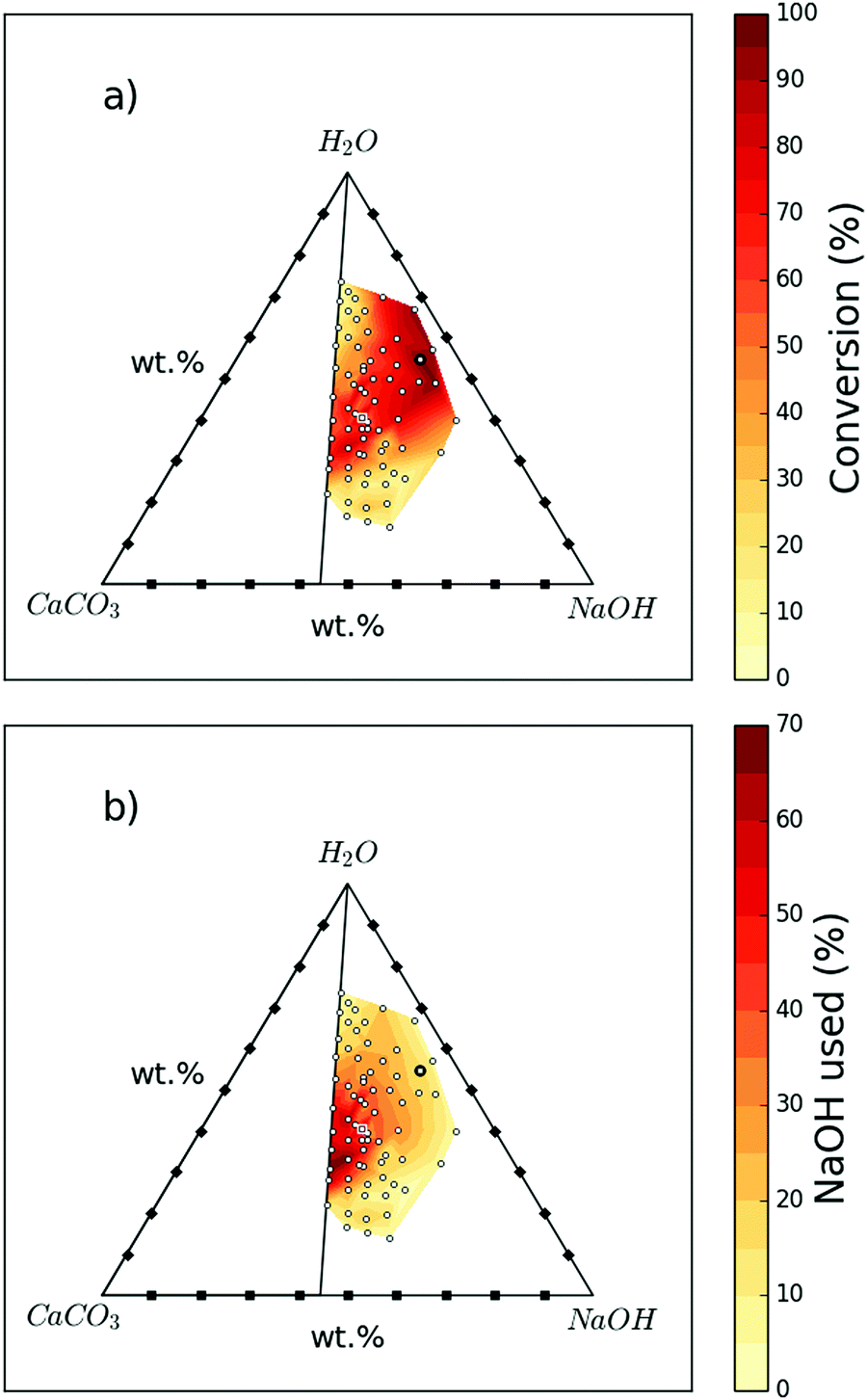 | ||
| Fig. 1 Influence on reaction progression of different starting mix compositions of H2O, CaCO3, and NaOH; the 71 white dots represent the measured data points while the sample highlighted with a black circle is “Sample 1” and that highlighted with a white square is “Sample 5”. (a) shows the conversion of CaCO3 to Ca(OH)2 for different starting mix compositions. (b) Shows the amount of NaOH consumed for different starting mix compositions. | ||
Fig. 1a summarises the conversion achieved at different starting compositions. Both high and low H2O![[thin space (1/6-em)]](https://www.rsc.org/images/entities/char_2009.gif) :NaOH ratios can result in reduced conversion. The highest conversions are generally achieved at higher ratios of NaOH solution to CaCO3. However, Fig. 1b shows that at these higher ratios, more NaOH remains unreacted, which will need to be separated and recycled. There does exist a region where both conversion and NaOH consumption efficiency are high, such as Samples 5 and Sample 6 (see Table S1, ESI†).
:NaOH ratios can result in reduced conversion. The highest conversions are generally achieved at higher ratios of NaOH solution to CaCO3. However, Fig. 1b shows that at these higher ratios, more NaOH remains unreacted, which will need to be separated and recycled. There does exist a region where both conversion and NaOH consumption efficiency are high, such as Samples 5 and Sample 6 (see Table S1, ESI†).
As shown in Fig. 2, the NaOH/CaCO3 molar ratios investigated were showing a similar bell-shaped trend in terms of conversion as a function of H2O/NaOH molar ratios. With an increase in NaOH/CaCO3 molar ratio, the maximum conversion increases up to a certain extent before decreasing; all the maximum conversions for all NaOH/CaCO3 ratios studied were detected in a H2O/NaOH range between 2.0–3.0. The maxima were both preceded and followed by lower reaction efficiencies. The lower conversions registered at milder NaOH concentrations, can be attributed to the lower ionic strength of the solutions. On the other hand, low conversions registered at higher NaOH concentrations may be attributed to the scarcity of H2O, leading to denser solutions and a hindered physical contact between the reactants. Moreover, the very high ionic strength of these solutions might prevent supersaturation conditions of the products Ca(OH)2 and Na2CO3·xH2O, hindering their precipitation.18
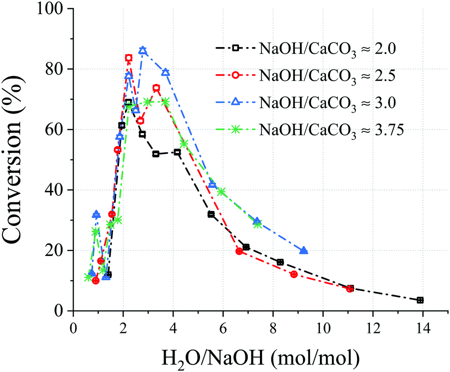 | ||
| Fig. 2 Chart showing the conversion vs. H2O/NaOH molar ratio for selected NaOH/CaCO3 molar ratios. A molar ratio of NaOH/CaCO3 = 2 is the stoichiometric for the decarbonisation reaction, and the CaCO3 content in all experiments presented was constant. The sample information is shown in Table S1 (ESI†) and those presented here are where NaOH/CaCO3 is: 2; Samples 19, 24, 26, 33, 30, 45, 54, 71, 64, 68, 59, 2.5; Samples 6, 13, 23, 29, 44, 57, 58, 63, 67, 69, 3; Samples 5, 8, 12, 22, 27, 40, 46, 48, 56, 62, 65, and 3.75; Samples 17, 18, 20, 28, 42, 47, 49, 50, 53, 61, 66. | ||
The XRD patterns for samples 1 and 5, shown in Fig. 3, confirm that the major phases in the solid product are Ca(OH)2, Na2CO3·H2O, and CaCO3; however, the CaCO3 peaks in Sample 1 exhibit a low intensity as it is almost completely consumed, which is in agreement with the TG/conversion data. In some samples (not shown here) Na2CO3 was also present and it is concluded that the CO2 is sequestered as either Na2CO3 or Na2CO3·H2O depending on the temperature, water activity, and NaOH concentration.19–21 As shown in Fig. 3, main peaks of Na2CO3 do overlap with those of Na2CO3·H2O, and both may be existing simultaneously. The possibility of methoxide formation was also investigated and discarded through analyses of XRD and TG data.
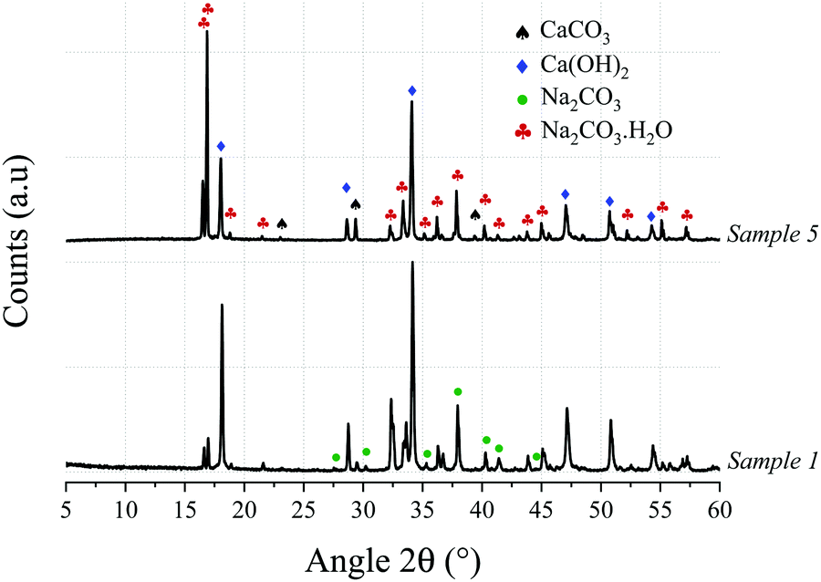 | ||
| Fig. 3 X-ray diffractograms of Samples 1 and 5, showing the presence of Ca(OH)2 and Na2CO3·H2O resulting from the de-carbonisation of the calcium carbonate via reaction with an aqueous NaOH solution. | ||
3.2 Applicability to industrial grade calcium carbonate
Calcium carbonate in nature is generally found as limestone rock which also contains other phases (mainly quartz) and impurities. For industrialisation of a decarbonisation process, it is essential that the developed technology is applicable to such raw materials. Therefore, an industrial grade limestone chalk containing a high quantity of impurities was tested. The oxide composition of the limestone chalk is presented in Table 1 and shows the presence of 21 wt% SiO2 as well as other minor impurities.| Al2O3 | CaO | Fe2O3 | K2O | MgO | Na2O | P2O5 | SiO2 | SrO | TiO2 | Others | LOI |
|---|---|---|---|---|---|---|---|---|---|---|---|
| 2.9 | 43.8 | 1.1 | 0.7 | 0.3 | 0.2 | 0.1 | 21.0 | 0.1 | 0.2 | 0.2 | 29.4 |
Thermogravimetric analysis of the limestone chalk (not shown here) indicated that the CaCO3 content was 73 wt%, suggesting that some of the Ca is present as silicates, when comparing with XRF data in Table 1. Samples 1L and 5L (Table 2) were prepared with the same compositions as Samples 1 and 5, respectively, but using the chalk instead of the reagent grade CaCO3 and correcting for the CaCO3 content of the chalk to maintain the same NaOH/CaCO3 ratios as Samples 1 and 5. The starting compositions and resulting conversions (obtained from the TG data shown in Fig. 4) are also shown in Table 2. A drop in conversion is observed when using limestone chalk, from 96% (Sample 1) and 86% (Sample 5) to 72% (Sample 1L) and 61% (Sample 5L), respectively. The XRD (Fig. 5) analyses also revealed that the SiO2/quartz remained unreacted.
| ID | Chalk (g) | NaOH (g) | H2O (g) | Chalk (wt%) | NaOH (wt%) | H2O (wt%) | Conversion (%) | NaOH used (%) |
|---|---|---|---|---|---|---|---|---|
| 1L | 10.00 | 33.60 | 49.20 | 10.8 | 36.2 | 53.0 | 71.8 | 12.5 |
| 5L | 10.07 | 8.77 | 11.01 | 33.7 | 29.4 | 36.9 | 60.9 | 40.8 |
 | ||
| Fig. 4 Thermogravimetric and derivative thermogravimetric analyses of the Samples 1L (solid lines) and 5L (dashed lines). | ||
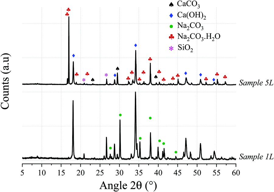 | ||
| Fig. 5 X-ray diffractograms of Samples 1L and 5L revealing the presence of Ca(OH)2 and Na2CO3·xH2O (where x = 0 and/or 1) and confirming applicability of the technology to industrial grade calcareous sources. SiO2 (quartz) remains inert through the reaction. | ||
3.3 Separation of the products
After the decarbonisation reaction, the major constituents of the mixture can include: CaCO3, Ca(OH)2, NaOH, Na2CO3 and/or Na2CO3·H2O, along with unreacted SiO2 (when using industrial grade material). Table 3 shows the solubility of these phases, at close to room temperature, in water, methanol, and ethanol. It is deduced that alcohols can be used as selective dissolution media to separate, and recover, unreacted/excess NaOH. Na2CO3 can then be separated from the calcium-containing components and silica, utilising the differences in their solubilities in water as the driving force for separation.| CaCO3 | Ca(OH)2 | Na2CO3 | SiO2 | NaOH | |
|---|---|---|---|---|---|
| g/100 g of water | 0.0014 | 0.155 | 29.4 | 0.0006 | 113 |
| g/100 g of methanol | — | — | 0.604 | — | 31 (28 °C) |
| g/100 g of ethanol | — | — | 0.24 | — | 17.3 (28 °C) |
3.4 Conceptual process design
The process for industrial decarbonisation of calcium carbonate with simultaneous production of sodium carbonate is now conceptualised and including separation procedures. The major reaction can proceed with high (e.g. Sample 1) or low (e.g. Sample 5) amounts of initial NaOH solution. These two scenarios encouraged us to design and create process flow diagrams for two processes which cover realistic situations, hereby named Process A (Fig. 6) and Process B (Fig. 7). When low amounts of solution are used initially, or the water is evaporated after the reaction, NaOH can be separated from Na2CO3 before separation from calcium compounds and silica (such as in Process A). When high amounts of solution are added initially, most sodium compounds can dissolve together, leaving behind mainly the calcium compounds and silica as undissolved solids (such as in Process B). Process A may also be adopted for high amounts of solution and vice versa.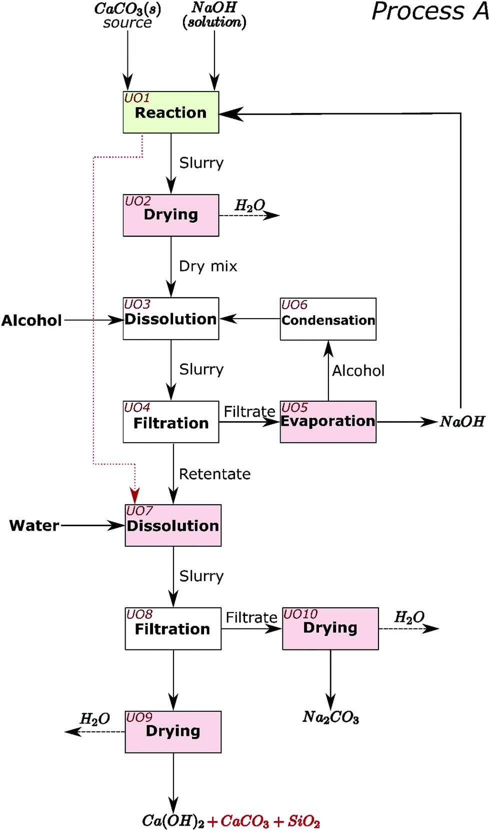 | ||
| Fig. 6 Conceptual process flow diagram/scheme for Process A. The decarbonisation reaction is carried out in Unit operation (UO) 1. The remaining steps are, UO2: drying of the slurry that results from UO1; UO3: dissolution of any excess/unreacted NaOH from the dry mix in alcohol; UO4: separation of the solid components from the NaOH containing permeate; UO5: evaporation of alcohol in the filtrate leaving NaOH that can be recycled to the process; UO6: condensation of the alcohol that is recycled to the process; UO7: dissolution of sodium carbonate in the retentate from UO4, with water. If the reaction in UO1 has no excess NaOH, then the slurry from UO1 can be sent straight to UO7 (red dotted line); UO8: separation of the solid components from the Na2CO3 solution; UO9: drying of the retentate to obtain Ca(OH)2 and any unreacted CaCO3 and SiO2; UO10: drying of the filtrate to obtain sodium carbonate. The dashed black arrows represent mass leaving the system which may also be recovered if desired. | ||
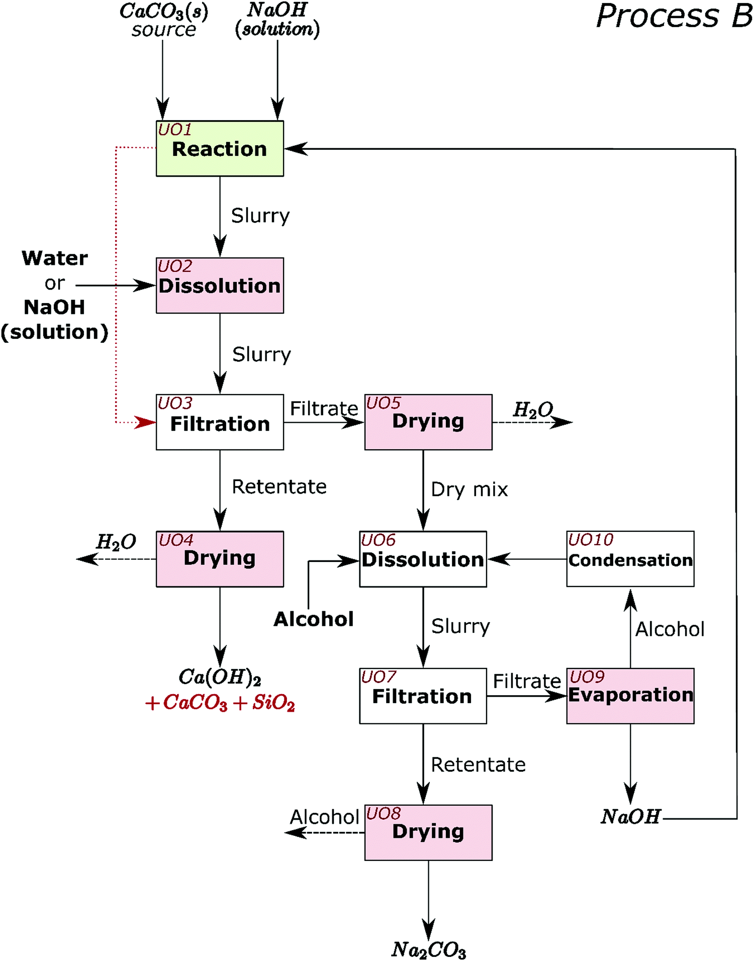 | ||
| Fig. 7 Conceptual process flow diagram/scheme for Process B. The decarbonisation reaction is carried out in Unit operation (UO) 1. The remaining steps are as follows, UO2: dissolution of sodium carbonate in the slurry from UO1 with water or NaOH solution; UO3: separation of the solid components from the solution of Na2CO3 and NaOH. If enough water is added in UO1 to dissolve all NaOH and Na2CO3 after reaction, then the slurry from UO1 can be sent straight to UO7 (red dotted line); UO4: drying of the retentate to obtain Ca(OH)2 and any unreacted CaCO3 and SiO2; UO5: drying of the filtrate to obtain a solid mixture of Na2CO3 and NaOH; UO6: dissolution of NaOH from the dry mix in alcohol; UO7: separation of the solid components from the Na2CO3 solution; UO8: drying of the retentate from UO7 to obtain sodium carbonate; UO9: evaporation of alcohol in the filtrate leaving NaOH that is recycled to the process; UO10: condensation of the alcohol that is recycled to the process. The dashed black arrows represent mass leaving the system which may also be recovered if desired. | ||
In Process A, NaOH is first separated from the main reaction products; while in Process B, NaOH and Na2CO3 are jointly separated. Different steps in the process are presented as unit operations (UO). The first unit operation (UO1) in both flowsheets (highlighted green in Fig. 6 and 7) is the heart of the process and is where the reaction between CaCO3, NaOH, and H2O occurs. At atmospheric pressure, this reaction can be carried out at temperatures up to the boiling point of the NaOH solution; ∼170 °C.22 At higher pressures, where the aqueous solution is stable, the reaction may also occur at higher temperatures. In the flowsheets, all UOs that may require thermal energy input are highlighted pink. This thermal energy may be used to evaporate liquids or to control the reaction equilibrium. In both flowsheets, the alcohol and unreacted NaOH can be recirculated. In UO10 of Process A and UO8 of Process B, hydrated sodium carbonate will convert to anhydrous above ∼90 °C.7 In UO2 of Process B it is proposed that additional NaOH can also be added at this stage, along with water and temperature control, to shift chemical equilibrium if necessary.
The energy performance of Processes A and B will depend mainly (∼80%) on overcoming the latent heats of water and alcohol for evaporation. The minimum vaporisation energy requirements per kg of Ca(OH)2 production are calculated for all samples, and shown in Table S1 (ESI†), using the heats of vaporisation of water and methanol from ref. 23 as well as solubility data in Table 3 (to calculate required heat of vaporisation); selected calculations are shown in Fig. 8. Up to 1.43 kg of Na2CO3 is produced alongside every kg of Ca(OH)2; if the conventional processes are considered, the production of these combined can demand 23648 kJ (13600 kJ per kg Na2CO3 × 1.43 kg Na2CO3 + 4200 kJ per kg Ca(OH)2 × 1.00 kg Ca(OH)2).24,25 Using the technology presented in this work, the energy requirements for Sample 1 in Process B is 42201 kJ and for Sample 5 in Process A is 19400 kJ. The latter is comparable with existing technologies but, along with simultaneous raw-material CO2 sequestration, the novel process also allows for use of lower-grade heat that could be generated renewably or sourced from waste heat sources, and avoids the high temperatures required for CaCO3 calcination. The energy performance of the developed technology can also improve when the initial compositions of NaOH and H2O are low (see Samples 6 and 19 in Table S1, ESI†), albeit at the cost of a lower conversion (under the tested conditions).
 | ||
| Fig. 8 Minimum vaporisation energy requirements for the various starting mix compositions of H2O, CaCO3, and NaOH to produce 1 kg of Ca(OH)2. Note that up to 1.4 kg of Na2CO3 is produced along with every kg of Ca(OH)2. Methanol is the alcohol used in separation and the heats of vaporisation of methanol and water are taken from ref. 23. Solubility data from Table S4 (ESI†) are also used for the calculations. The 63 white dots represent the data points while the sample highlighted with a black circle is “Sample 1” and that highlighted with a white square is “Sample 5”. In order to visualize the spread, eight of the most energy intensive samples from Table S1 (ESI†) were excluded from the energy plot; these are the samples in which both Process A and Process B require >100 MJ kg−1 Ca(OH)2 and are shown as red circles in the figures. (a) Shows the energy requirements for Process A. (b) Shows the energy requirements for Process B. | ||
4. Additional discussion
It is generally believed that the calcination of limestone is unavoidable in cement clinker manufacture;14,26,27 however, the obtained calcium compounds from our process (mainly Ca(OH)2), which may also contain silica, can be used to produce cement clinker when mixed with appropriate raw materials and thermally treated.15,28 In fact, in modern precalciner cement kiln configurations, the limestone is already calcined to form CaO before reaching the rotary kiln where clinker is formed.29 Any impurities contained in the products of our process originated from the limestone, and thus, are exactly the same as in conventional cement manufacture, except that they may contain slightly more sodium depending on separation efficiency. Otherwise, the only compositional difference between the limestone and the products of our process is that the CO2 component has been replaced with H2O. The cement can be manufactured in existing cement plants by replacing the limestone in the raw meal of conventional clinker manufacture with the products from our decarbonisation process. This will enable reduced fuel consumption in the pre-calciner, which uses more than 60% of the energy in pyro processing, or allow the pre-calciner part of the kiln configuration to become redundant and repurposed, e.g., for the calcination of clay to produce blended cements such as LC3 which are currently being commercialised at a global scale.30–32 The Ca(OH)2 from our process can also be used to produce lime pozzolan cements (without the need for clinkering), as well as to capture carbon from other processes.For every tonne of CaCO3 converted to Ca(OH)2, in the here-developed process, an almost equal quantity of sodium carbonate is produced, and this can be advantageous. Annual production of natural soda ash (sodium carbonate) is currently 58 million tonnes, but global reserves are limited and not geographically widespread.10 Industrially, Na2CO3 is mainly produced through the Solvay process which requires large amount of thermal energy and CaCO3 calcination.33 The produced Na2CO3 can have several uses in the industry: (1) for flue gas CO2 sequestration through the production of NaHCO3,34,35 (2) as an alkali activator for cements, either directly or in the production of activators such as sodium silicates,36,37 (3) in the production of precipitated calcium carbonate from brine for use as a cement admixture,38 (4) to regenerate the necessary NaOH,21,39–41 and/or (5) sold for the manufacture of other commodities (e.g. glass). The challenge is that overall demand for Na2CO3 is currently smaller than that for cement in two orders of magnitude; therefore, the use of Na2CO3 has to be increased to maximise the incentive of the proposed process for global industrial implementation. It should be noted, however, that the excess Na2CO3 can also be stored, thus sequestering CO2 in this stable mineral form without a risk of leakage.
NaOH can have a high carbon footprint, which originates from electricity use during its manufacture via electrolysis of seawater;42,43 however, with the use of green electricity (e.g., wind turbines), this method of decarbonisation may offer negligible overall CO2 emissions. The availability of NaOH is not intrinsically limited, since NaOH can be manufactured through electrolysis of sea water, and the seas and oceans of Earth contain ∼2 × 10¹⁶ tonnes of Na; the limitation here is the energy demand of the chlor-alkali process (which can be met by renewables) and the utilisation of the very large quantity of Cl2 that would be produced as a co-product (but diminishing the CaCl2 co-product from soda ash manufacture). The issue associated with Cl2 may also be reduced by adopting new technologies such as electrolysis of sea water that produces HCl rather than Cl2,44 as HCl can be widely used for water and wastewater treatment.
Today, most of the Cl2 produced in the world is used to make four plastics: polyvinyl chloride (PVC), epoxies, polycarbonate, and polyurethane.45 PVC, which contains 60% chlorine by weight, is the most produced out of these, and although some industrial uses of chlorine decline due to environmental health concerns and regulations, that of PVC is increasing. The total global production volume of PVC in 2018 amounted to 44 Mt. It is forecasted that the global market size of PVC will grow to nearly 60 Mt in 2025.46 The construction industry is the most significant consumer of PVC, as most is used to manufacture building products; thus, the construction industry drives chlorine production.45 Nonetheless, PVC is associated with adverse environmental and health impacts during its production, while in use, and after use; thus, posing concern in its use in sustainable construction.47 Consequently, also due to the large difference in demand between cement and PVC, the wide scale industrial application of our technology may be constrained until development of regeneration processes of NaOH from Na2CO3, alternative NaOH production processes, or increased demand for Cl2/HCl. Nonetheless, limited replacement of global manufacturing with our technology is still feasible in current market demands.
Future work around this technology should focus on optimisation of the novel decarbonisation process, further development of the separation techniques, testing various cements produced from the separated lime products, enhanced utilization of sodium carbonate in cementitious materials, and routes for the regeneration of NaOH from Na2CO3 as well as novel NaOH production processes. This should be followed by scale-up through pilot demonstration trials and retrofit or grass-root industrial cement process and plant designs.
5. Conclusions
The feasibility of a novel method to decarbonise calcium carbonate and co-produce sodium carbonate through simultaneous sequestration of CO2, and under ambient conditions, is established. The core of the process involves the reaction of calcium carbonate with a sodium hydroxide aqueous solution to produce calcium hydroxide and sodium carbonate. A range of conditions have been identified to achieve 70–80% conversion and the reaction is fast (≤5 min). The technique is also proven on natural limestone, and the silica in the limestone remained unreacted; thus, demonstrating industrial applicability. The products and unreacted reactants can be separated through selective dissolution, using water and alcohol. The feasibility of scale-up is also demonstrated through encouraging energy performance calculations with two conceptual process designs. The presented technology can offer a route for diminishing the substantial raw-material CO2 emissions associated with the calcination of limestone.The largest environmental impact of this work can be achieved through adoption of the presented technology in the cement industry. To achieve climate goals, the cement industry requires radical transformation within the next few decades. The process presented here can enable carbon neutrality in cement and lime manufacturing, while avoiding post-combustion CO2 capture. However, the environmental benefits may only be realised if there is availability of green electricity to supply the necessary sodium hydroxide, or development of new sodium hydroxide production processes. The process presented here is also an alternative to the Solvay process and a novel and viable route to producing soda ash.
Author contributions
T. H. and H. K. discovered and conceptualized the technology. T. H., H. K., J. L. P., and M. S. developed the technology and designed the methodology and experiments. T. H., M. S., and C. L. W. carried out experiments. T. H. drafted the original manuscript. T. H., H. K., and J. L. P. reviewed and edited the manuscript, acquired funding, and supervised M. S. and C. L. W.Conflicts of interest
There are no conflicts to declare.Acknowledgements
The authors would like to acknowledge the financial support of the Engineering and Physical Sciences Research Council (grant EP/R025959/1) and CEMEX Asia Research AG. The XRF analysis was performed at HADES/MIDAS facility at the University of Sheffield established with financial support from EPSRC and BEIS (grant EP/T011424/1). The authors would also like to thank the advisory group who contributed to this work: Alan Maries, Mark Tyrer, John Stennett, Nestor-Isaias Quintero-Mora, Magnus Nyberg, Olga Chowaniec, and Juan-Carlos Martinez.References
- H. Kolb, Preparation of carbonates, ZKG Int., 2001, 54(5), 262 CAS.
- K. L. Scrivener, V. M. John and E. M. Gartner, Eco-efficient cements: Potential economically viable solutions for a low-CO2 cement-based materials industry, Cement Concrete Res., 2018, 114, 2–26 CrossRef CAS.
- H. F. W. Taylor, Cement Chemistry, Telford, London, 1997 Search PubMed.
- A. Ghosh and A. Chatterjee, Iron Making and Steelmaking: Theory and Practice, PHI Learning Pvt. Ltd, New Delhi, 2008 Search PubMed.
- L. V. Fisher and A. R. Barron, The recycling and reuse of steelmaking slags – A review, Resour. Conserv. Recy., 2019, 146, 244–255 CrossRef.
- V. Manovic and E. J. Anthony, Lime-based sorbents for high-temperature CO2 capture - A review of sorbent modification methods, Int. J. Env. Res. Pub. He, 2010, 7(8), 3129–3140 CrossRef CAS.
- W. H. Shearon, W. H. Louviere and R. M. Laperouse, Cane sugar refining, Ind. Eng. Chem., 1951, 43(3), 552–563 CrossRef CAS.
- S. T. Anderson, Cost implications of uncertainty in CO2 storage resource estimates: A review, Nat. Resour. Res., 2017, 26(2), 137–159 CrossRef CAS.
- R. S. Middleton and S. Yaw, The cost of getting CCS wrong: Uncertainty, infrastructure design, and stranded CO2, Int. J. Greenh. Gas. Con., 2018, 70, 1–11 CrossRef.
- U.S. Geological Survey, Mineral commodity summaries 2020: National Minerals Information Center, 2019, https://www.usgs.gov/centers/nmic/mineral-commodity-summaries.
- R. M. Andrew, Global CO2 emissions from cement production, Earth Syst. Sci. Data, 2018, 10(1), 195 CrossRef.
- T. F. Stocker, et al., Climate Change 2013: The Physical Science Basis, Contribution of working group I to the fifth assessment report of the intergovernmental panel on climate change, Cambridge University Press, New York, 2013 Search PubMed.
- P. Friedlingstein, et al., Global carbon budget 2019, Earth Syst. Sci. Data, 2019, 11(4), 1783–1838 CrossRef.
- G. Habert, S. A. Miller, V. M. John, J. L. Provis, A. Favier, A. Horvath and K. L. Scrivener, Environmental impacts and decarbonization strategies in the cement and concrete industries, Nat. Rev. Earth Environ., 2020, 1, 559–573 CrossRef.
- L. D. Ellis, A. F. Badel, M. L. Chiang, R. J. Y. Park and Y. M. Chiang, Toward electrochemical synthesis of cement – An electrolyzer-based process for decarbonating CaCO3 while producing useful gas streams, Proc. Natl. Acad. Sci. U. S. A., 2020, 117(23), 12584–12591 CrossRef CAS.
- European Commission, Integrated Pollution Prevention and Control (IPCC) – Reference Document on Best Available Techniques in the Large Volume Inorganic Chemicals – Solids and Others industry, 2007 Search PubMed.
- United States Environmental Protection Agency (EPA), Technical Support Document for the Soda Ash Manufacturing Sector: Proposed Rule for Mandatory Reporting of Greenhouse Gases, Washington, DC, 2009 Search PubMed.
- G. H. Nancollas and N. Purdie, The kinetics of crystal growth, Q. Rev., Chem. Soc., 1964, 18(1), 1–20 RSC.
- H. P. Eugster and G. I. Smith, Mineral equilibria in the Searles Lake evaporites, California, J. Petrol., 1965, 6(3), 473–522 CrossRef CAS.
- C. Monnin and J. Schott, Determination of the solubility products of sodium carbonate minerals and an application to trona deposition in Lake Magadi (Kenya), Geochim. Cosmochim. Acta, 1984, 48(3), 571–581 CrossRef CAS.
- M. Mahmoudkhani and D. W. Keith, Low-energy sodium hydroxide recovery for CO2 capture from atmospheric air – Thermodynamic analysis, Int. J. Greenh. Gas. Con., 2009, 3(4), 376–384 CrossRef CAS.
- A. Lach, et al., A new Pitzer parameterization for the binary NaOH–H2O and ternary NaOH–NaCl–H2O and NaOH–LiOH–H2O systems up to NaOH solid salt saturation, from 273.15 to 523.15K and at saturated vapor pressure, J. Solut. Chem., 2015, 44(7), 1424–1451 CrossRef CAS.
- B. J. McBride, NASA Glenn Coefficients for Calculating Thermodynamic Properties of Individual Species, National Aeronautics and Space Administration, John H. Glenn Research Center at Lewis Field, 2002 Search PubMed.
- Y. Wu, H. Xie, T. Liu, Y. Wang, F. Wang, X. Gao and B. Liang, Soda ash production with low energy consumption using proton cycled membrane electrolysis, Ind. Eng. Chem. Res., 2019, 58(8), 3450–3458 CrossRef CAS.
- F. Schorcht, I. Kourti, B. M. Scalet, S. Roudier and L. D. Sancho, Best available techniques (BAT) Reference Document for the Production of Cement, Lime and Magnesium Oxide. European Commission Joint Research Centre Institute for Prospective Technological Studies (Report EUR 26129 EN Luxembourg: Publications Office of the European Union, 2013).
- M. Schneider, Process technology for efficient and sustainable cement production, Cement Concrete Res., 2015, 78, 14–23 CrossRef CAS.
- M. Schneider, M. Romer, M. Tschudin and H. Bolio, Sustainable cement production—present and future, Cement Concrete Res., 2011, 41(7), 642–650 CrossRef CAS.
- T. Hanein, F. P. Glasser and M. N. Bannerman, Thermodynamic data for cement clinkering, Cement Concrete Res., 2020, 132, 106043 CrossRef CAS.
- H. G. van Oss and A. C. Padovani, Cement manufacture and the environment: Part I: chemistry and technology, J. Ind. Ecol., 2002, 6(1), 89–105 CrossRef CAS.
- F. Zunino, F. Martirena and K. Scrivener, Limestone calcined clay cements (LC3), ACI Mater. J., 2021, 118(3), 49–60 Search PubMed.
- M. Sharma, S. Bishnoi, F. Martirena and K. Scrivener, Limestone calcined clay cement and concrete: A state-of-the-art review, Cement Concrete Res., 2021, 149, 106564 CrossRef.
- T. Hanein, K. C. Thienel, F. Zunino, A. T. M. Marsh, M. Maier, B. Wang, M. Canut, M. C. G. Juenger, M. Ben Haha, F. Avet, A. Parashar, L. A. Al-Jaberi, R. S. A. Reyes, A. Alujas Diaz, K. L. Scrivener, S. A. Bernal, J. L. Provis, T. Sui, S. Bishnoi and J. F. M. Hernández, Clay calcination technology: State-of-the-art review by the RILEM TC 282-CCL, Mater. Struct., 2021 DOI:10.1617/s11527-021-01807-6.
- M. Rumayor, A. Dominguez-Ramos and A. Irabien, Toward the decarbonization of hard-to-abate sectors: A case study of the soda ash production, ACS Sustainable Chem. Eng., 2020, 8(32), 11956–11966 CrossRef.
- T. O. Nelson, L. J. Coleman, D. A. Green and R. P. Gupta, The dry carbonate process: Carbon dioxide recovery from power plant flue gas, Energy Procedia, 2009, 1(1), 1305–1311 CrossRef.
- J. H. Lee, D. W. Lee, C. Kwak, K. Kang and J. H. Lee, Technoeconomic and environmental evaluation of sodium bicarbonate production using CO2 from flue gas of a coal-fired power plant, Ind. Eng. Chem. Res., 2019, 58(34), 15533–15541 CrossRef.
- F. Shaqour, M. Ismeik and M. Esaifan, Alkali activation of natural clay using a Ca (OH)2/Na2CO3 alkaline mixture, Clay Miner., 2017, 52(4), 485–496 CrossRef.
- J. L. Provis and J. S. J. Van Deventer, Alkali Activated Materials: State-of-the-Art Report, RILEM TC 224-AAM, Springer Science & Business Media, 2013, vol. 13 Search PubMed.
- L. McDonald, F. P. Glasser and M. S. Imbabi, A new, carbon-negative precipitated calcium carbonate admixture (PCC-A) for low carbon Portland cements, Materials, 2019, 12(4), 554 CrossRef CAS PubMed.
- A. Simon, T. Fujioka, W. E. Price and L. D. Nghiem, Sodium hydroxide production from sodium carbonate and bicarbonate solutions using membrane electrolysis, Sep. Purif. Technol., 2014, 127, 70–76 CrossRef CAS.
- J. Liu, et al., Hydrogen-motivated electrolysis of sodium carbonate with extremely low cell voltage, Chem. Commun., 2018, 54(29), 3582–3585 RSC.
- O. N. Fedyaeva and A. A. Vostrikov, Processing of pulp and paper industry wastes by supercritical water gasification, Russ. J. Phys. Chem. B, 2019, 13(7), 1071–1078 CrossRef CAS.
- I. Garcia-Herrero, M. Margallo, R. Onandía, R. Aldaco and A. Irabien, Life Cycle Assessment model for the chlor-alkali process: A comprehensive review of resources and available technologies, Sustainable Prod. Consum., 2017, 12, 44–58 CrossRef.
- J. Hong, W. Chen, Y. Wang, C. Xu and X. Xu, Life cycle assessment of caustic soda production: A case study in China, J. Clean. Prod., 2014, 66, 113–120 CrossRef CAS.
- H. W. Lin, R. Cejudo-Marín, A. W. Jeremiasse, K. Rabaey, Z. Yuan and I. Pikaar, Direct anodic hydrochloric acid and cathodic caustic production during water electrolysis, Sci. Rep., 2016, 6(1), 1–4 CrossRef.
- J. Vallette, C. Murtagh, M. Dedeo and R. Stamm, Chlorine and Building Materials A Global Inventory of Production Technologies, Markets, and Pollution Phase 1: Africa, The Americas, and Europe, Healthy Building Network, Washington, DC, 2018 Search PubMed.
- M. Garside, Plastic industry worldwide: Statista Dossier on the global plastic industry, 2020 Search PubMed.
- E. K. Petrović and L. K. Hamer, Improving the healthiness of sustainable construction: Example of polyvinyl chloride (PVC), Buildings, 2018, 8(2), 28 CrossRef.
Footnotes |
| † Electronic supplementary information (ESI) available: Table S1: the starting compositions of H2O, NaOH, and CaCO3 in each sample tested. The calculated conversion is also presented as well as the amount (%) of NaOH used. The minimum energy requirements per kg Ca(OH)2, calculated from the heats of vaporisation of water and alcohol (methanol), for Processes A and B are also shown. Note that up to 1.4 kg of Na2CO3 is produced alongside 1 kg of Ca(OH)2. This data set was used to generate Fig. 1 and 8 in the manuscript. See DOI: 10.1039/d1ee02637b |
| ‡ PTFE (Teflon) is suitable for mixing in hyper-alkaline environments and is stable up to ∼250 °C. |
| This journal is © The Royal Society of Chemistry 2021 |